WO2024134874A1 - 劣化促進方法、及び、劣化促進装置 - Google Patents
劣化促進方法、及び、劣化促進装置 Download PDFInfo
- Publication number
- WO2024134874A1 WO2024134874A1 PCT/JP2022/047621 JP2022047621W WO2024134874A1 WO 2024134874 A1 WO2024134874 A1 WO 2024134874A1 JP 2022047621 W JP2022047621 W JP 2022047621W WO 2024134874 A1 WO2024134874 A1 WO 2024134874A1
- Authority
- WO
- WIPO (PCT)
- Prior art keywords
- degradation
- test
- polymeric material
- bending
- polymer material
- Prior art date
- Legal status (The legal status is an assumption and is not a legal conclusion. Google has not performed a legal analysis and makes no representation as to the accuracy of the status listed.)
- Ceased
Links
Images


Classifications
-
- G—PHYSICS
- G01—MEASURING; TESTING
- G01N—INVESTIGATING OR ANALYSING MATERIALS BY DETERMINING THEIR CHEMICAL OR PHYSICAL PROPERTIES
- G01N17/00—Investigating resistance of materials to the weather, to corrosion, or to light
-
- G—PHYSICS
- G01—MEASURING; TESTING
- G01N—INVESTIGATING OR ANALYSING MATERIALS BY DETERMINING THEIR CHEMICAL OR PHYSICAL PROPERTIES
- G01N3/00—Investigating strength properties of solid materials by application of mechanical stress
- G01N3/32—Investigating strength properties of solid materials by application of mechanical stress by applying repeated or pulsating forces
- G01N3/34—Investigating strength properties of solid materials by application of mechanical stress by applying repeated or pulsating forces generated by mechanical means, e.g. hammer blows
Definitions
- This disclosure relates to a deterioration acceleration method and a deterioration acceleration device.
- Non-Patent Document 1 Compared to inorganic compounds such as metals, ceramics, and glass, polymeric materials are prone to deterioration and have inferior durability. The deterioration of polymeric materials is thought to be influenced by three factors: "environmental conditions” such as ultraviolet light, heat, water, and chemicals; “mechanical conditions” such as tension, compression, bending, and impact; and “special conditions” such as electrical action (Non-Patent Document 1).
- environmental conditions such as ultraviolet light, heat, water, and chemicals
- mechanical conditions such as tension, compression, bending, and impact
- special conditions such as electrical action
- Non-Patent Document 2 discloses degradation behavior due to light and heat.
- Non-Patent Document 3 discloses degradation behavior due to infrared rays.
- Non-Patent Document 4 discloses degradation behavior due to bending stress.
- Non-Patent Document 5 deals with environmental stress cracking of plastics.
- compound degradation of polymeric materials by applying environmental degradation factors and bending stress.
- This disclosure has been made in light of the above circumstances, and the purpose of this disclosure is to provide a technology that can efficiently promote the complex degradation of polymeric materials.
- the degradation promotion method is a degradation promotion method for promoting the complex degradation of a polymeric material, which includes a first step of applying environmental degradation factors, including light, to the polymeric material using an additional device, a second step of applying repeated bending stress to the polymeric material using a bending mechanism, and a third step of measuring the degradation progress state of the polymeric material based on the results of infrared spectroscopic analysis of the polymeric material using a measuring device.
- the degradation acceleration device is a degradation acceleration device that accelerates the complex degradation of a polymeric material, and includes an additional device that applies environmental degradation factors, including light, to the polymeric material, a bending mechanism that applies repeated bending stress to the polymeric material, and a measuring device that measures the degradation progress state of the polymeric material based on the results of infrared spectroscopic analysis of the polymeric material.
- This disclosure provides a technology that can efficiently promote the complex degradation of polymeric materials.
- FIG. 1 is a side view showing the overall configuration of the deterioration acceleration device.
- FIG. 2 is a cross-sectional view taken along line A-A' in FIG.
- FIG. 3 is a perspective view showing the configuration of the support member, the upper fixture, the lower fixture, the test piece, and the bending jig.
- FIG. 4 is a perspective view showing a state in which the support member shown in FIG. 3 is bent.
- FIG. 5 is a perspective view showing a state in which the bending jig shown in FIG. 3 has been moved to a retreated position.
- FIG. 6 is a block diagram showing the configuration of the control device, the infrared spectroscopic analyzer, and each device connected to the control device and the infrared spectroscopic analyzer.
- FIG. 1 is a side view showing the overall configuration of the deterioration acceleration device.
- FIG. 2 is a cross-sectional view taken along line A-A' in FIG.
- FIG. 3 is a
- FIG. 7 is a flowchart showing the operation of the degradation promoting device.
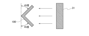
- FIG. 8 is an explanatory diagram showing how the light from the light source is irradiated onto the test specimen.
- FIG. 9 is an explanatory diagram showing how the light from the light source is irradiated onto the test specimen.
- FIG. 10 is an explanatory diagram showing how the light from the light source is irradiated onto the test specimen.
- FIG. 11 is an explanatory diagram showing the results of accelerated deterioration tests.
- FIG. 12 is an explanatory diagram showing the results of accelerated deterioration tests.
- FIG. 13 is a block diagram showing the hardware configuration of the control device.
- the present disclosure discloses a method and an apparatus for accelerating the composite degradation of a polymeric material. Specifically, the composite degradation of the polymeric material is accelerated by applying environmental degradation factors, including light simulating sunlight, and repeated bending stress to the polymeric material. The composite degradation is accelerated, and the progress of degradation of the polymeric material is measured by infrared spectroscopy.
- the degradation acceleration device is a device for accelerating the composite degradation of a polymeric material.
- the polymeric material is a plastic material that is flexible enough to be bent and is expected to be degraded by ultraviolet light. Examples of the polymeric material include polyethylene and polypropylene.
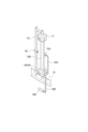
- FIG. 1 is a side view showing the overall configuration of the deterioration acceleration device according to this embodiment.
- FIG. 2 is a cross-sectional view taken from the A-A' direction shown in FIG. 1.
- the deterioration acceleration device comprises a housing 1, a control device 2 arranged near the side of the housing 1, and an infrared spectroscopic analysis device 3 arranged near the control device 2.
- the housing 1 includes additional devices (light source 31, temperature regulator 32, humidity regulator 33) that apply environmental degradation factors including light simulating sunlight to a polymeric material test specimen 100, mechanical parts (rotation mechanism 51, bending mechanism 52, drive mechanism 53) that apply repeated bending stress or the like to the test specimen 100, and an observation part (imaging part 71, measurement part 72) that observes the deterioration progress state of the test specimen 100.
- additional devices light source 31, temperature regulator 32, humidity regulator 33
- mechanical parts rotation mechanism 51, bending mechanism 52, drive mechanism 53
- observation part imaging part 71, measurement part 72
- the housing 1 has a hollow rectangular parallelepiped shape and an enclosed internal structure. Legs 4 are provided at the bottom of the housing 1. The housing 1 is supported by the legs 4 and placed on a flat floor surface.
- a support 13 is installed inside the housing 1, connecting the center of the top plate 11 and the center of the bottom plate 12.
- An upper disk 14 and a lower disk 15 (fixed members) are connected to the support 13.
- a light source 31 is installed in the portion of the support 13 between the upper disk 14 and the lower disk 15.
- the light source 31 irradiates light simulating sunlight in the surrounding area (360° radial direction). That is, the light source 31 is installed in the center of the lower disk 15 (fixed member) and irradiates light onto multiple test specimens 100. The light source 31 irradiates light including light in the ultraviolet range onto the test specimens 100 present in the surrounding area. The light source 31 may also irradiate light in the visible range or infrared range.
- the light source 31 is, for example, an ultraviolet fluorescent lamp, a xenon lamp, a sunshine carbon lamp, or a metal halide lamp.
- the light source 31 may be a combination of such a lamp and a filter to make the spectral radiation distribution of the emitted light closer to that of sunlight.
- the light source 31 that can be used is one that performs tests conforming to "ISO 11341", “JIS K 5600-7-7", “JIS K 7350-2", etc.
- a temperature regulator 32 that maintains the interior of the housing 1 at a predetermined humidity is provided on the top surface of the upper disk 14.
- a humidity regulator 33 that maintains the interior of the housing 1 at a predetermined temperature is provided on the inner side of the housing 1.
- the support 13 can be rotated around the longitudinal direction as the rotation axis by the rotation mechanism 51.
- the rotation mechanism 51 by controlling the rotation mechanism 51, the upper disk 14 and the lower disk 15 can be rotated around the support 13 (central axis).
- the rotation mechanism 51 is equipped with, for example, a stepping motor, and can rotate the upper disk 14 and the lower disk 15 and stop them at a predetermined angle. By rotating the lower disk 15 (fixed member), the rotation mechanism 51 controls the positioning of the multiple test specimens 100 in the imaging range and measurement position of the imaging unit 71 and the measurement unit 72 in sequence.
- a number of support members 16 (10 in this example) are erected at equal intervals along the circumferential direction on the upper surface of the lower disk 15.
- a lower fixing device 18 (see Figure 1) is installed near the side of each support member 16, and an upper fixing device 17 (see Figure 1) that forms a pair with the lower fixing device 18 is installed above the lower fixing device 18.
- the upper fixing device 17 is connected to and supported by the upper end of the support member 16.
- Figure 3 is a perspective view showing the configuration of the support member 16 and the upper fixture 17, lower fixture 18, and test specimen 100 installed near the side of the support member 16. As shown in Figure 3, a rectangular test specimen 100 is placed between the upper fixture 17 and the lower fixture 18. In other words, each test specimen 100 is installed on the circumference of the circular lower disk 15 (fixing member) (see Figure 2).
- test specimen 100 The upper end of the test specimen 100 is connected to the upper fixture 17.
- the lower end of the test specimen 100 is connected to the lower fixture 18.
- the test specimen 100 can be attached and detached by manipulating the upper fixture 17 and the lower fixture 18.
- the bending mechanism 52 is installed at approximately the center of the support member 16 in the vertical direction.
- the bending mechanism 52 bends the support member 16 by a predetermined angle under the control of the control device 2. For example, the bending mechanism 52 bends the support member 16 to ⁇ 30°, ⁇ 60°, ⁇ 90°, ⁇ 120°, or ⁇ 180°.
- Two bending jigs 19A, 19B are connected to the lower fixing fixture 18.
- the tip ends PA, PB of each bending jig 19A, 19B are cylindrical.
- the tip ends PA, PB of the two bending jigs 19A, 19B can clamp approximately the center of the test piece 100.
- the test specimen 100 can be bent. That is, as shown in FIG. 3, the center of the test specimen 100 is clamped between the tips PA and PB of the two bending jigs 19A and 19B. Therefore, when the support member 16 is bent by a predetermined angle, as shown in FIG. 4, the test specimen 100 connected to the upper fixture 17 is bent by the predetermined angle with the part clamped by the tips PA and PB as the fulcrum. That is, the bending mechanism 52 switches between extending and bending the test specimen 100, and applies a bending stress.
- the lower fixture 18 is equipped with a drive mechanism 53.
- the drive mechanism 53 retracts the two bending jigs 19A and 19B individually under the control of the control device 2. Specifically, as shown in FIG. 5, the drive mechanism 53 can retract the bending jig 19B by tilting it downward. Similarly, the drive mechanism 53 can retract the bending jig 19A by tilting it downward.
- the position where bending jigs 19A and 19B are tilted downward is referred to as the "retracted position.”
- the position where bending jigs 19A and 19B clamp test piece 21 is referred to as the "operating position.”
- the bending jig 19A on the inner side is moved to a retracted position to prevent the bending jig 19A from blocking the light irradiated by the light source 31 to the test piece 100.
- the driving mechanism 53 can drive (move) each of the bending jigs 19A and 19B to either the operating position or the retracted position.
- an imaging unit 71 is installed at an appropriate position on the inner side of the housing 1. That is, the imaging unit 71 is installed around the lower disk 15 (fixed member).
- the imaging unit 71 is, for example, an optical camera, a CCD camera, or a microscope.
- the imaging unit 71 is installed at a position where it can capture an image of the vicinity of the center of the test piece 100. That is, the imaging unit 71 captures an image of the test piece 100.
- the measuring unit 72 is disposed inside the hollow interior of the housing 1. That is, the measuring unit 72 is disposed around the lower disk 15 (fixed member). The measuring unit 72 is attached to the infrared spectroscopic analysis device 3 via an optical fiber. The measuring unit 72 is pressed against the test object 100 under the control of the infrared spectroscopic analysis device 3, and functions as a part for acquiring the light irradiated onto the test object 100.
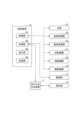
- [Configurations and Functions of the Control Device 2 and the Infrared Spectroscopic Analysis Device 3] 6 is a block diagram showing the configuration of the control device 2, the infrared spectroscopic analysis device 3, and each device connected to the control device 2 and the infrared spectroscopic analysis device 3.
- the devices are the above-mentioned additional devices (light source 31, temperature regulator 32, humidity regulator 33), mechanical units (rotation mechanism 51, bending mechanism 52, drive mechanism 53), and observation unit (imaging unit 71, measurement unit 72).
- the control device 2 and the infrared spectroscopic analysis device 3 may be physically configured as one measurement device.
- the infrared spectroscopic analysis device 3 is connected to the measurement unit 34 via optical fiber, and is also electrically and physically connected to the control device 2.
- the infrared spectroscopic analysis device 3 is, for example, a Fourier transform infrared spectrophotometer conforming to "JIS K 0117".
- the infrared spectroscopic analysis device 3 may be any analytical device capable of performing infrared spectroscopic analysis of the test specimen 100.
- the infrared spectroscopic analyzer 3 is a device that performs infrared spectroscopic analysis of the test specimen 100. Only the optical fiber is introduced inside the housing 1, and during measurement, the infrared spectroscopic analyzer 3 presses the measuring unit 34 against the test specimen 100 and measures the absorbance of each of the carbonyl groups and methylene groups absorbed by the test specimen 100 via the optical fiber. The infrared spectroscopic analyzer 3 outputs the measured values of each absorbance to the control device 2.
- the carbonyl groups and methylene groups are examples of observation data. Any data that can measure the deterioration progression state of the test specimen 100 will suffice.
- the control device 2 is electrically and physically connected to the light source 31, the temperature regulator 32, the humidity regulator 33, the rotation mechanism 51, the bending mechanism 52, the drive mechanism 53, and the imaging unit 71. As shown in FIG. 6, the control device 2 includes a control unit 91, a processing unit 92, a display unit 93, and a memory unit 94.
- the control unit 91 controls the on/off and illuminance of the light source 31.
- the control unit 91 controls the temperature regulator 32 to keep the temperature inside the housing 1 at a predetermined temperature.
- the control unit 91 controls the humidity regulator 33 to keep the humidity inside the housing 1 at a predetermined level.
- the control unit 91 controls the rotation mechanism 51 to rotate the support 13, and thus the upper disk 14 and the lower disk 15.
- the control unit 91 controls the support 13 to rotate in 36° increments, so that the ten test specimens 100 mounted on the lower disk 15 are positioned within the imaging range of the imaging unit 71 and the measurement position of the measurement unit 72.
- the control unit 91 controls the bending mechanisms 52 provided for each of the ten test specimens 100, thereby controlling the support members 16 corresponding to each test specimen 100 to bend at a predetermined angle.
- the control unit 91 controls the bending angles of the ten test specimens 100 to be 30°, 60°, 90°, 120°, 180°, -30°, -60°, -90°, -120°, and -180°, respectively.
- the bending mechanisms 52 are preferably configured to be capable of carrying out tests conforming to "JIS P8115", “JIS-K5600", "JIS C 3005", etc.
- the bending angle of each test body 100 can be set arbitrarily.
- the bending angles of all 10 test bodies 100 may be set to the same angle, or the 10 test bodies 100 may be divided into groups of 5 and the test bodies 100 in each group may be set to the same angle.
- the multiple test bodies 100 may be divided into test bodies to be bent at a first angle and test bodies to bent at a second angle, and the bending mechanism 52 may extend and bend each test body 100 at the divided angle.
- all 10 test bodies 100 may be set to different bending angles.
- the control unit 91 controls the bending mechanisms 52 provided for each of the 10 test specimens 100, thereby controlling the number of times that the support members 16 corresponding to each test specimen 100 are repeatedly bent and extended to a predetermined number of times. For example, the control unit 91 controls the number of times that the 10 test specimens 100 are bent and extended to 5, 10, 15, and 20 times.
- the number of times each test body 100 is bent and stretched can be set arbitrarily.
- the number of times each test body 100 is bent and stretched may be set to be the same, or the ten test bodies 100 may be divided into groups of five and the number of times each test body 100 is bent and stretched may be set to be the same for each group. That is, the multiple test bodies 100 may be divided into test bodies 100 that are repeatedly stretched and bent a first number of times and test bodies 100 that are repeatedly stretched and bent a second number of times, and the bending mechanism 52 may be configured to bend and stretch each test body 100 the number of times set for that group. The number of times each test body 100 is bent and stretched may be set to be different for all ten test bodies 100.
- the control unit 91 controls the drive mechanism 53 to control the two bending jigs 19A and 19B to either the operating position or the retracted position described above.
- the processing unit 92 controls the imaging unit 71 to capture an image of the test specimen 100.
- the processing unit 92 acquires the captured image of the test specimen 100.
- the processing unit 92 determines whether the carbonyl index value of the test specimen 100 has increased to or above a threshold value, and whether the crack depth of the test specimen 100 has progressed to or above a threshold value, and controls whether or not to apply environmental degradation factors by the additional devices (light source 31, temperature regulator 32, humidity regulator 33), and whether or not to apply bending stress, etc. by the mechanical units (rotation mechanism 51, bending mechanism 52, drive mechanism 53) depending on each determination result. For example, the processing unit 92 switches the light source 31 on and off. For example, the processing unit 92 stops the application of bending stress by the bending mechanism 52.
- the processing unit 92 stops the deterioration acceleration device when it is determined that the carbonyl index value of the test specimen 100 or the crack depth of the test specimen 100 is equal to or greater than a preset value, or when the total time of the weather resistance test is equal to or greater than a preset time, and otherwise continues the deterioration acceleration test.
- the display unit 93 displays, for example, an image of the test specimen 100, various measurement values such as the thickness of the test specimen 100 and the depth of the crack.
- the display unit 93 may display information indicating an alarm when the crack depth reaches or exceeds a predetermined value.
- the memory unit 94 stores, for example, captured images of the test specimen 100, and various measurement values such as the thickness of the test specimen 100 and the depth of cracks.
- Step S1 First, the infrared spectroscopic analyzer 3 performs infrared spectroscopic analysis of the test specimen 100. Specifically, the control device 2 controls the rotation mechanism 51 to move one of the ten test specimens 100 to the front of the measurement unit 34. The infrared spectroscopic analyzer 3 presses the measurement unit 34 against the test specimen 100 and measures the absorbance of each of the carbonyl groups and methylene groups absorbed by the test specimen 100. The infrared spectroscopic analyzer 3 also measures the absorbance of each of the remaining test specimens 100.
- Step S2 Next, the control device 2 calculates the initial carbonyl index value of each test specimen 100 using the formula (1) based on the measured absorbance of the carbonyl group and the methylene group of each test specimen 100.
- I is the absorbance at each wave number.
- I0 is the baseline absorbance at each wave number by the baseline method. The absorption position may vary depending on the state of the test specimen 100 and the measurement conditions. Therefore, the calculation formula for the carbonyl index value is not limited to formula (1).
- Step S3 Next, the control device 2 controls the light source 31, the temperature regulator 32, and the humidity regulator 33 to carry out the weather resistance test for A hours under the preset conditions.
- the weather resistance test is set in accordance with "JIS K 5600-7-7" and "JIS K 7350-2" with a black panel temperature of 63°C, a temperature inside the tank of 38°C, and a humidity of 50% RH.
- the water spray time is 18 minutes out of 2 hours.
- the light source 31 is turned on to continuously irradiate the entire surroundings (360° directions) centered on the light source 31 with light simulating sunlight for a certain period of time.
- the ultraviolet radiation intensity at wavelengths of 300 nm to 400 nm is 60 W/ m2 . Under these conditions, accelerated deterioration of the test specimen 100 is carried out for 100 hours.
- Step S4 Next, the infrared spectroscopic analyzer 3 performs infrared spectroscopic analysis again on the test specimens 100. Specifically, the infrared spectroscopic analyzer 3 measures the absorbance of the carbonyl group and the methylene group of each test specimen 100 again.
- Step S5 Next, the control device 2 calculates the carbonyl index value of each test specimen 100 after the weather resistance test has been carried out for A hours, based on the remeasured absorbances of the carbonyl group and the methylene group.
- Step S6 Next, the control device 2 calculates the percentage increase in the carbonyl index value after the weather resistance test relative to the carbonyl index value before the weather resistance test for each test specimen 100.
- the control device 2 determines whether or not there is a test specimen 100 whose carbonyl index value has increased by more than B % (e.g., 0.1%) preset by the user.
- Step S7 If there is no test specimen 100 whose carbonyl index value has increased by B% or more, the control device 2 judges whether the total time of the weather resistance test has exceeded a designated C hours (e.g., 3000 hours). If the total time of the weather resistance test has not exceeded C hours, the process returns to step S3. If the total time of the weather resistance test has exceeded C hours, all processing is terminated.
- a designated C hours e.g., 3000 hours
- Step S8 When there is a test specimen 100 whose carbonyl index value has increased by B% or more, the control device 2 controls the bending mechanism 52 to bend the test specimen 100 under preset conditions. For example, the control device 2 controls the test specimen 100 to bend at D° (e.g., ⁇ 30°, ⁇ 60°, ⁇ 90°, ⁇ 120°, ⁇ 180°) as shown in Figures 9 and 10. The control device 2 also repeats this bending and stretching operation a predetermined number E of times (e.g., 10 times, 30 times).
- D° e.g., ⁇ 30°, ⁇ 60°, ⁇ 90°, ⁇ 120°, ⁇ 180°
- the control device 2 also repeats this bending and stretching operation a predetermined number E of times (e.g., 10 times, 30 times).
- Step S9 Next, the control device 2 controls the imaging unit 71 to capture an image of each test object 100. For example, the control device 2 captures an image of a bent portion of each test object 100. The user observes the deterioration state of each test object 100 from the captured image of each test object 100.
- Step S10 Next, the control device 2 analyzes the captured images of each test piece 100 and measures the thickness of each test piece 100 and the depth of any cracks occurring in each test piece 100 .
- Step S11 Finally, the control device 2 calculates, for each test specimen 100, the percentage of the crack depth relative to the test specimen 100 based on the thickness of the test specimen 100 and the crack depth. The control device 2 determines whether or not there is a test specimen 100 whose calculated value is greater than F% (e.g., 50%) preset by the user. If there is no test specimen 100 whose calculated value is greater than F%, the process returns to step S3. If there is a test specimen 100 whose calculated value is greater than F%, all processing is terminated.
- F% e.g. 50%
- the deterioration acceleration device repeats the loop of steps S3 to S11, for example by bending the test specimens 100 each time the carbonyl index value increases by 0.1%, and stops according to the branching conditions of the program that were set in advance when the crack depth in all test specimens 100 is 50% or more of the test specimens 100, or when the total time of the weather resistance test exceeds 3000 hours, i.e., when the number of loops of steps S3 to S11 has reached 30.
- Figure 11 shows examples of the carbonyl index value increase rate and crack depth when the degradation acceleration device was stopped under multiple conditions set for one type of test specimen.
- the test specimen was made of polypropylene with a size of about 4 cm x 10 cm, a total thickness of about 5 mm, and a thickness of about 1 mm at the hinge.
- the test specimen was set so that light could be irradiated to the outside of the bent part of the test specimen, and the bending angles were set to 30°, 60°, 90°, 120°, and 180°, and the number of bending times was set to 10 and 30 times.
- test specimens under conditions 8 to 10 which had a large bending angle, were judged to have a crack depth of 50% or more after 25, 20, and 15 loops, respectively.
- test results mentioned above show that this polymeric material can be used outdoors for long periods of time if used with a bending angle of 90° or less. This cannot be easily predicted from a simple combination of weather resistance tests and bending resistance tests.
- the bending angle and number of times can be set arbitrarily according to the purpose, and are not limited to these values.
- Figure 12 shows the conditions set for three types of test specimens, and examples of the carbonyl index value increase rate and crack depth when the degradation acceleration device is stopped.
- the test specimens used were polypropylene, measuring approximately 4 cm x 10 cm, with an overall thickness of approximately 5 mm and a thickness of approximately 1 mm at the hinge.
- the specimens were set up so that light could be irradiated onto the outside of the bent parts, with bending angles set to 90°, 120°, and 180°, and the number of folds set to 30.
- test specimen A It was found that the crack depth of test specimen A could be suppressed to less than 50% if it was bent up to 120 degrees. However, for test specimens such as test specimen A, whose carbonyl index value does not increase in the first place, it is possible to evaluate them using the bending test alone without applying the deterioration acceleration method of this embodiment.
- test specimen B increased, it was found that the crack depth could be suppressed to less than 50% if it was bent up to 90 degrees. Furthermore, even when test specimen C was bent up to 180 degrees, the crack depth was suppressed to less than 50%. In either case, long-term use is possible by setting an appropriate bending angle based on the evaluation results using the deterioration acceleration method of this embodiment.
- the degradation acceleration device includes additional devices (light source 31, temperature regulator 32, humidity regulator 33) that apply environmental degradation factors including light to the polymer material test specimen 100, mechanisms (rotation mechanism 51, bending mechanism 52, drive mechanism 53) that apply repeated bending stress or the like to the test specimen 100, and measuring devices (control device 2, infrared spectroscopic analyzer 3) that measure the deterioration progress state of the test specimen 100 based on the infrared spectroscopic analysis results of the test specimen 100, so that it is possible to simply and efficiently evaluate the resistance of the polymer material to the combined degradation caused by light and bending stress.
- additional devices light source 31, temperature regulator 32, humidity regulator 33
- mechanisms rotation mechanism 51, bending mechanism 52, drive mechanism 53
- control device 2 infrared spectroscopic analyzer 3
- the control device 2 of this embodiment described above can be realized, for example, as shown in FIG. 13, by using a general-purpose computer system equipped with a CPU 901, memory 902, storage 903, communication device 904, input device 905, and output device 906.
- the memory 902 and storage 903 are storage devices.
- the CPU 901 executes a specific program loaded onto the memory 902, thereby realizing each function of the control device 2.
- the control device 2 may be implemented in one computer.
- the control device 2 may be implemented in multiple computers.
- the control device 2 may be a virtual machine implemented in a computer.
- the program for the control device 2 may be stored in a computer-readable recording medium such as a HDD, SSD, USB memory, CD, or DVD.
- the computer-readable recording medium is, for example, a non-transitory recording medium.
- the program for the control device 2 may also be distributed via a communication network.
Landscapes
- Life Sciences & Earth Sciences (AREA)
- Biochemistry (AREA)
- Analytical Chemistry (AREA)
- Pathology (AREA)
- Immunology (AREA)
- Physics & Mathematics (AREA)
- Health & Medical Sciences (AREA)
- Chemical & Material Sciences (AREA)
- General Physics & Mathematics (AREA)
- General Health & Medical Sciences (AREA)
- Biodiversity & Conservation Biology (AREA)
- Ecology (AREA)
- Environmental Sciences (AREA)
- Environmental & Geological Engineering (AREA)
- Testing Resistance To Weather, Investigating Materials By Mechanical Methods (AREA)
Priority Applications (2)
| Application Number | Priority Date | Filing Date | Title |
|---|---|---|---|
| JP2024565540A JPWO2024134874A1 (https=) | 2022-12-23 | 2022-12-23 | |
| PCT/JP2022/047621 WO2024134874A1 (ja) | 2022-12-23 | 2022-12-23 | 劣化促進方法、及び、劣化促進装置 |
Applications Claiming Priority (1)
| Application Number | Priority Date | Filing Date | Title |
|---|---|---|---|
| PCT/JP2022/047621 WO2024134874A1 (ja) | 2022-12-23 | 2022-12-23 | 劣化促進方法、及び、劣化促進装置 |
Publications (1)
| Publication Number | Publication Date |
|---|---|
| WO2024134874A1 true WO2024134874A1 (ja) | 2024-06-27 |
Family
ID=91587899
Family Applications (1)
| Application Number | Title | Priority Date | Filing Date |
|---|---|---|---|
| PCT/JP2022/047621 Ceased WO2024134874A1 (ja) | 2022-12-23 | 2022-12-23 | 劣化促進方法、及び、劣化促進装置 |
Country Status (2)
| Country | Link |
|---|---|
| JP (1) | JPWO2024134874A1 (https=) |
| WO (1) | WO2024134874A1 (https=) |
Citations (3)
| Publication number | Priority date | Publication date | Assignee | Title |
|---|---|---|---|---|
| JPH0431739A (ja) * | 1990-05-28 | 1992-02-03 | Suga Shikenki Kk | 疲労耐候試験方法 |
| JP2018159553A (ja) * | 2017-03-22 | 2018-10-11 | スガ試験機株式会社 | 耐候性試験機用試料保持ボックスおよび該ボックスを備えた耐候性試験機 |
| US20210292526A1 (en) * | 2020-03-18 | 2021-09-23 | University Of South Florida | Geomembranes and methods for making and using the same |
-
2022
- 2022-12-23 WO PCT/JP2022/047621 patent/WO2024134874A1/ja not_active Ceased
- 2022-12-23 JP JP2024565540A patent/JPWO2024134874A1/ja active Pending
Patent Citations (3)
| Publication number | Priority date | Publication date | Assignee | Title |
|---|---|---|---|---|
| JPH0431739A (ja) * | 1990-05-28 | 1992-02-03 | Suga Shikenki Kk | 疲労耐候試験方法 |
| JP2018159553A (ja) * | 2017-03-22 | 2018-10-11 | スガ試験機株式会社 | 耐候性試験機用試料保持ボックスおよび該ボックスを備えた耐候性試験機 |
| US20210292526A1 (en) * | 2020-03-18 | 2021-09-23 | University Of South Florida | Geomembranes and methods for making and using the same |
Non-Patent Citations (2)
| Title |
|---|
| FUKAYA, NORIO; NIWA, AKIO; HIROSE, SHIGEKI: "Degradation Evaluation of Polymeric Materials Subjected to Accelerated Exposure", REPORT OF AICHI CENTER FOR INDUSTRY AND SCIENCE TECHNOLOGY, JP, 1 January 2015 (2015-01-01), JP, pages 136 - 137, XP009555788, DOI: Owari Textile Research Centra * |
| OGATA MASAKI, MOCHIZUKI YOSUKE, KATSUMATA NOBUYUKI, ISHIGURO TERUO, YATSUSHIRO KOJI, ABE OSAMU, YAMADA HIROYUKI: "Study on Evaluation Method for Light Resistance of Plastic Materials (2nd Report)", FY2019 RESEARCH REPORT (NO. 3), 1 January 2019 (2019-01-01), XP093185318 * |
Also Published As
| Publication number | Publication date |
|---|---|
| JPWO2024134874A1 (https=) | 2024-06-27 |
Similar Documents
| Publication | Publication Date | Title |
|---|---|---|
| CN104053982B (zh) | 使用无电极等离子体光源加速光降解的测试装置和方法 | |
| US20230316465A1 (en) | System, method and apparatus for macroscopic inspection of reflective specimens | |
| US8963089B2 (en) | Drug detection device and drug detection method | |
| CN107036888B (zh) | 模拟多环境的同步辐射原位成像拉伸试验机及其试验方法 | |
| EP3264033B1 (en) | System and method to measure the thickness of ophthalmic lenses | |
| CN106802273B (zh) | 曝光加速的户外试验设备 | |
| CN110702613B (zh) | 试样全偏振二向反射分布测试装置及方法 | |
| US10054556B2 (en) | Structure electron beam inspection system for inspecting extreme ultraviolet mask and structure for discharging extreme ultraviolet mask | |
| EP2233898A2 (en) | Infrared spectrophotometer and attachment therefor | |
| WO2024134874A1 (ja) | 劣化促進方法、及び、劣化促進装置 | |
| ES2726992T3 (es) | Monitoreo de proceso para curado por UV | |
| JP2004163422A (ja) | スペクトル測定用試料保持体および分光光度計 | |
| CN222748478U (zh) | 一种面料紫外线遮挡效果测试装置 | |
| WO2025004153A1 (ja) | 劣化促進装置 | |
| WO2025203367A1 (ja) | 劣化促進装置 | |
| WO2024116343A1 (ja) | 劣化試験装置及び劣化試験方法 | |
| Gu et al. | Linking accelerated laboratory and outdoor exposure results for PV polymeric materials: a mechanistic study of EVA | |
| CN206670893U (zh) | 一种用于镜片生产的mtf检测装置 | |
| KR20210107530A (ko) | 반사계, 분광 광도계, 또는 엘립소미터 시스템을 사용하는 샘플 맵핑에 적용되는 세타-세타 샘플 포지셔닝 스테이지 | |
| CN214539203U (zh) | 一种含水样本的无损光学检测装置 | |
| CN114839138B (zh) | 一种含水样本的无损光学检测装置 | |
| Zhao et al. | Study on the influence of semi-conductive layer on near-infrared spectrum of cable insulation | |
| CN223272149U (zh) | 一种膜片疲劳测试平台 | |
| CN119959235B (zh) | 一种新能源汽车底盘焊接缺陷检测设备 | |
| CN223727687U (zh) | 一种除草剂斑迹的太赫兹光谱检测装置 |
Legal Events
| Date | Code | Title | Description |
|---|---|---|---|
| 121 | Ep: the epo has been informed by wipo that ep was designated in this application |
Ref document number: 22969257 Country of ref document: EP Kind code of ref document: A1 |
|
| WWE | Wipo information: entry into national phase |
Ref document number: 2024565540 Country of ref document: JP |
|
| NENP | Non-entry into the national phase |
Ref country code: DE |
|
| 122 | Ep: pct application non-entry in european phase |
Ref document number: 22969257 Country of ref document: EP Kind code of ref document: A1 |