WO2024127632A1 - 回転電機 - Google Patents
回転電機 Download PDFInfo
- Publication number
- WO2024127632A1 WO2024127632A1 PCT/JP2022/046377 JP2022046377W WO2024127632A1 WO 2024127632 A1 WO2024127632 A1 WO 2024127632A1 JP 2022046377 W JP2022046377 W JP 2022046377W WO 2024127632 A1 WO2024127632 A1 WO 2024127632A1
- Authority
- WO
- WIPO (PCT)
- Prior art keywords
- electric machine
- rotating electric
- axis
- magnetic flux
- input
- Prior art date
- Legal status (The legal status is an assumption and is not a legal conclusion. Google has not performed a legal analysis and makes no representation as to the accuracy of the status listed.)
- Ceased
Links
Images


Classifications
-
- H—ELECTRICITY
- H02—GENERATION; CONVERSION OR DISTRIBUTION OF ELECTRIC POWER
- H02K—DYNAMO-ELECTRIC MACHINES
- H02K1/00—Details of the magnetic circuit
- H02K1/06—Details of the magnetic circuit characterised by the shape, form or construction
- H02K1/22—Rotating parts of the magnetic circuit
- H02K1/27—Rotor cores with permanent magnets
- H02K1/2706—Inner rotors
- H02K1/272—Inner rotors the magnetisation axis of the magnets being perpendicular to the rotor axis
- H02K1/274—Inner rotors the magnetisation axis of the magnets being perpendicular to the rotor axis the rotor consisting of two or more circumferentially positioned magnets
- H02K1/2753—Inner rotors the magnetisation axis of the magnets being perpendicular to the rotor axis the rotor consisting of two or more circumferentially positioned magnets the rotor consisting of magnets or groups of magnets arranged with alternating polarity
- H02K1/276—Magnets embedded in the magnetic core, e.g. interior permanent magnets [IPM]
Definitions
- This application relates to a rotating electric machine.
- rotating electrical machines with a multi-layered permanent magnet structure thin permanent magnets are used. Thin permanent magnets have the problem of increased eddy current loss. In particular, rotating electrical machines with a multi-layered structure of three or more layers have significantly increased eddy current loss compared to structures with two or fewer layers.
- magnets rotating electric machines with conventional multi-layered structures were not designed to reduce eddy current loss in permanent magnets. From this point on, permanent magnets will simply be referred to as magnets.
- the present application has been made to solve the above-mentioned problems, and aims to provide a structure that can reduce eddy current loss in magnets in rotating electrical machines that have a multi-layered magnet structure.
- the rotating electric machine of the present application is a rotating electric machine having a cylindrical stator having a stator core and a coil to which three-phase AC current is input, and a cylindrical rotor arranged on the inner diameter side of the stator with a gap between the stator and the rotor, the rotor has a rotor core having multiple magnet slots and multiple magnets arranged in each of the multiple magnet slots, the multiple magnets are arranged in a multi-layer structure of two or more layers in the radial direction to form one pole, a bridge is formed between the multiple magnet slots and the outer peripheral surface of the rotor core, the outer peripheral surface of the rotor core has two or more pairs of low permeability parts symmetrical with respect to the d axis per pole, and at least a portion of the circumferential area of all low permeability parts is included in the circumferential area of the bridge.
- the outer circumferential surface of the rotor core has two or more pairs of low permeability sections symmetrical with respect to the d-axis per pole, and at least a portion of the circumferential area of all low permeability sections is included in the circumferential area of the bridge, thereby reducing eddy current loss in the magnets.
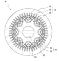
- FIG. 1 is a cross-sectional view of a rotating electric machine according to a first embodiment.
- 2 is a cross-sectional view of a region of one pole of the rotating electric machine according to the first embodiment; 2 is an enlarged cross-sectional view of a region of one pole of the rotating electric machine according to the first embodiment;
- 10 is a cross-sectional view of a region of one pole of a rotating electric machine of Comparative Example 1 according to the first embodiment.
- FIG. 4 is a diagram showing phase currents flowing through coils of the rotating electric machine according to the first embodiment;
- FIG. FIG. 11 is a diagram showing magnet eddy current loss in a rotating electric machine of Comparative Example 1 according to the first embodiment;
- FIG. 11 is a diagram showing a d-axis current when two types of currents are subjected to dq transformation in the first embodiment.
- 13 is a diagram showing an analysis result in which the amplitudes of harmonic components of the d-axis magnetic flux are arranged when two types of current are input to the rotating electric machine of Comparative Example 1 according to the first embodiment.
- FIG. 13 is a diagram showing an analysis result in which the amplitudes of harmonic components of the d-axis current are arranged when two types of current are input to the rotating electric machine of Comparative Example 1 according to the first embodiment.
- FIG. 13 is a diagram showing an analysis result in which the amplitudes of harmonic components of the d-axis current are arranged when two types of current are input to the rotating electric machine of Comparative Example 1 according to the first embodiment.
- FIG. 11 is a diagram showing an analysis result in which the amplitudes of harmonic components of the d-axis magnetic flux are arranged when two types of current are input to the rotating electric machine according to the first embodiment.
- FIG. 11 is a diagram showing an analysis result in which the amplitudes of harmonic components of the d-axis current are arranged when two types of current are input to the rotating electric machine according to the first embodiment.
- FIG. 13 is a cross-sectional view of a region of one pole of a rotating electric machine of Comparative Example 2 according to the first embodiment.
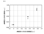
- FIG. 10 is a diagram showing the relationship between the amplitude of a 12th-order component of a d-axis magnetic flux and the amplitude of a 12th-order component of a d-axis current in the rotating electric machine according to the first embodiment.
- FIG. 5 is a diagram showing the relationship between the amplitude of a twelfth-order component of the d-axis magnetic flux and magnet eddy current loss in the rotating electric machine according to the first embodiment.
- FIG. 13A and 13B are diagrams illustrating a difference in amplitude of a 12th-order component of d-axis magnetic flux for the structure of a first cutout portion in the rotating electric machine according to the first embodiment.
- FIG. 13 is a diagram showing a difference in amplitude of the 12th-order component of d-axis magnetic flux for the first-layer bridge structure in the rotating electric machine according to the first embodiment.
- FIG. 13A and 13B are diagrams illustrating a difference in amplitude of a 12th-order component of d-axis magnetic flux for the structure of a second cutout portion in the rotating electric machine according to the first embodiment.
- 13 is a diagram showing a difference in amplitude of the 12th-order component of d-axis magnetic flux for the second-layer bridge structure in the rotating electric machine according to the first embodiment.
- FIG. 13A and 13B are diagrams illustrating a difference in amplitude of a 12th-order component of d-axis magnetic flux for the structure of a second cutout portion in the rotating electric machine according to the first embodiment.
- 13 is a diagram showing a difference in amplitude of the 12th-order component of d-axis magnetic flux for the second-layer bridge structure in the rotating electric machine
- FIG. 13A and 13B are diagrams illustrating a difference in amplitude of a 12th-order component of d-axis magnetic flux for the structure of a second cutout portion in the rotating electric machine according to the first embodiment.
- 13 is a diagram showing a difference in amplitude of the 12th-order component of d-axis magnetic flux for the third-layer bridge structure in the rotating electric machine according to the first embodiment.
- FIG. 13 is a diagram showing a difference in amplitude of the 12th-order component of d-axis magnetic flux for the first-layer bridge structure in the rotating electric machine according to the first embodiment.
- FIG. 13 is a diagram showing a difference in amplitude of the 12th-order component of d-axis magnetic flux for the first-layer bridge structure in the rotating electric machine according to the first embodiment.
- FIG. 13 is a diagram showing a difference in amplitude of the 12th-order component of d-axis magnetic flux for the second-layer bridge structure in the rotating electric machine according to the first embodiment.
- FIG. 13 is a diagram showing a difference in amplitude of the 12th-order component of d-axis magnetic flux for the third-layer bridge structure in the rotating electric machine according to the first embodiment.
- FIG. 11 is a cross-sectional view of a region of one pole of a rotating electric machine according to a second embodiment.
- FIG. 11 is a cross-sectional view of a region of one pole of a rotating electric machine according to a third embodiment.
- FIG. 13 is a cross-sectional view of a region of one pole of a rotating electric machine according to a fourth embodiment.
- FIG. 13 is a cross-sectional view of a region of one pole of a rotating electric machine according to a fifth embodiment.
- FIG. 13 is a cross-sectional view of a region of one pole of a rotating electric machine according to a sixth embodiment.
- FIG. 13 is a cross-sectional view of a region of one pole of a rotating electric machine according to a seventh embodiment.
- FIG. 13 is a cross-sectional view of a region of one pole of a rotating electric machine according to an eighth embodiment of the present invention.
- 13 is a cross-sectional view of a region of one pole of a rotating electric machine according to a ninth embodiment.
- Fig. 1 is a cross-sectional view of a rotating electric machine according to embodiment 1.
- Fig. 1 is a cross-sectional view in a direction perpendicular to a rotation axis.
- the rotating electric machine 1 according to this embodiment is composed of a stator 10 and a rotor 20 that is coaxially arranged on the inner diameter side of the stator 10.
- the stator 10 is composed of a cylindrical back core 11, teeth 12 extending from the back core 11 toward the inner diameter side, and coils 13 wound around the teeth 12.
- the back core 11 and teeth 12 are integrally formed, and the back core 11 and teeth 12 form a stator core.
- the coils 13 are wound around the teeth 12 using slots that are areas surrounded by adjacent teeth 12 and the back core 11.
- the rotor 20 is composed of a cylindrical rotor core 21 and magnets 22 inserted into magnet slots 23 formed in the rotor core 21.
- a rotating shaft 30 is fixed to the center of the rotor core 21.
- Bearings are arranged on both sides of the rotating shaft 30 in the axial direction, and the rotor 20 is installed to be rotatable relative to the stator 10 around the rotating shaft 30.
- the direction parallel to the rotating shaft 30 is referred to as the axial direction
- the direction in which the rotor 20 rotates is referred to as the circumferential direction
- the direction perpendicular to the axial direction is referred to as the radial direction.
- the stator core and rotor core 21 are made, for example, of electromagnetic steel sheets stacked in the axial direction.
- the magnets 22 are permanent magnets.
- the magnet slots 23 are formed in three layers, with pairs of magnet slots facing each other so that the distance between them narrows toward the inner diameter side.
- the magnets 22 are inserted into a total of six magnet slots 23.
- six permanent magnets inserted into the six magnet slots 23 respectively constitute one pole.
- the white arrows in FIG. 1 indicate the magnetization direction of each magnet 22.
- Each magnet 22 constituting one pole is flat and magnetized in a direction parallel to the short side and in the same radial direction.
- the rotor 20 is composed of eight poles, and is configured so that the magnetization directions of adjacent poles alternate between the inner diameter side and the outer diameter side.
- the rotating electric machine 1 of this embodiment is an 8-pole, 48-slot distributed winding embedded magnet rotating electric machine.
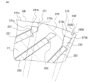
- FIG. 2 is a cross-sectional view of one pole area of a rotating electric machine according to this embodiment.
- the central direction of the magnetic flux of one pole is the d-axis, and the direction electrically perpendicular to this d-axis is the q-axis.
- a pair of first layer magnet slots 231, second layer magnet slots 232, and third layer magnet slots 233 are formed so that the distance between them narrows toward the inner diameter side with the d-axis as the center of the rotor core 21.
- a pair of first layer magnets 221 are inserted into the pair of first layer magnet slots 231, a pair of second layer magnets 222 are inserted into the pair of second layer magnet slots 232, and a pair of third layer magnets 223 are inserted into the pair of third layer magnet slots 233.
- a pair of first cutouts 241 are formed on the outer circumferential surface of the rotor core 21 at symmetrical positions with respect to the d-axis, and a pair of second cutouts 242 are formed at a position farther away from the d-axis than the first cutouts 241.
- the magnetic permeability of the first cutout portion 241 and the second cutout portion 242 is smaller than the magnetic permeability of the rotor core 21. That is, the first cutout portion 241 and the second cutout portion 242 are also referred to as the first low magnetic permeability portion and the second low magnetic permeability portion, respectively.
- FIG. 3 is an enlarged cross-sectional view of one pole region of a rotating electric machine according to this embodiment.
- FIG. 3 is an enlarged cross-sectional view of the vicinity of the first cutout portion 241 and the second cutout portion 242.
- a first layer bridge 271, a second layer bridge 272, and a third layer bridge 273 are respectively formed on the rotor core 21 in the portion where the first layer magnet slot 231, the second layer magnet slot 232, and the third layer magnet slot 233, which are flux barriers, face the outer peripheral surface of the rotor core 21.
- the first cutout portion 241 is formed so that the outer peripheral surface between the start point 241a of the first cutout portion, which is the end point of the first cutout portion 241 closest to the d axis, and the end point 241b of the first cutout portion, which is the end point farthest from the d axis, is located more inward than the outermost peripheral surface of the rotor core 21.
- the end point 241b of the first cutout portion is located between the start point 271a of the first layer bridge, which is the end point of the first layer bridge 271 closest to the d axis, and the end point 271b of the first layer bridge, which is the end point farthest from the d axis.
- At least a part of the first cutout portion 241 is formed in the area of the first layer bridge 271.
- at least a part of the circumferential area of the first cutout portion 241 is included in the circumferential area of the first layer bridge 271.
- the second cutout portion 242 is formed so that the outer peripheral surface between the start point 242a of the second cutout portion, which is the end point of the second cutout portion 242 closest to the d axis, and the end point 242b of the second cutout portion, which is the end point farthest from the d axis, is located more inward than the outermost peripheral surface of the rotor core 21.
- the start point 242a of the second cutout portion is located between the start point 273a of the third layer bridge, which is the end point of the third layer bridge 273 closest to the d axis, and the end point 273b of the third layer bridge, which is the end point farthest from the d axis.
- At least a part of the second cutout portion 242 is formed in the area of the third layer bridge 273.
- at least a part of the circumferential area of the second cutout portion 242 is included in the circumferential area of the third layer bridge 273.
- FIG. 4 is a cross-sectional view of a region of one pole of a rotating electric machine of Comparative Example 1 that does not have a first notch portion and a second notch portion in this embodiment.
- the black arrows in FIG. 4 indicate magnetic flux that penetrates the magnet (hereinafter, referred to as magnet-penetrating magnetic flux).
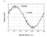
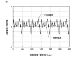
- FIG. 5 is a diagram showing phase currents that flow through the coil 13 of the rotating electric machine in this embodiment.
- the solid line is a waveform of a PWM current by a general triangular wave carrier comparison type PWM (Pulse Width Modulation) inverter drive control.
- PWM Pulse Width Modulation
- the dashed line is a waveform of an ideal current in which all harmonic components are removed from the PWM current and only the fundamental wave component is extracted.
- the PWM current is a current calculated by a simulation of the PWM inverter drive control.
- the condition of the PWM inverter drive control was set to a condition of synchronous 15-pulse control in which 15 periods of the carrier waveform are included in one fundamental wave period of the three-phase current.
- FIG. 5 shows only the current of one phase of the three-phase current, and does not show the current of the remaining two phases.
- the current waveforms of the remaining two phases are different in phase from the current waveforms shown in FIG. 5 by 120° in electrical angle.
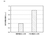
- Figure 6 is a diagram showing magnet eddy current loss when two types of current are input to the rotating electric machine of Comparative Example 1 shown in Figure 4.
- the left side shows magnet eddy current loss when an ideal current is input
- the right side shows magnet eddy current loss when a PWM current is input.
- the vertical axis is a relative value based on the magnet eddy current loss when a PWM current is input. Compared to when an ideal current is input, when a PWM current is input, approximately five times the magnet eddy current loss occurs.
- Figure 7 is a diagram showing the d-axis current when the two types of current shown in Figure 5 are dq converted.
- the ideal current does not contain harmonic components, so naturally there is almost no pulsation in the dq converted d-axis current.
- the PWM current contains harmonic components, there is a large pulsation in the dq converted d-axis current. This pulsation of the d-axis current causes harmonic flux fluctuations in the path of the magnet through-field magnetic flux shown in Figure 4, resulting in increased magnet eddy current loss.
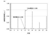
- FIG. 8 is a diagram showing the analysis results of Fourier series expansion of the d-axis magnetic flux waveform when two types of currents are input to the rotating electric machine of Comparative Example 1 shown in FIG. 4, and arranging the amplitudes of the harmonic components.
- FIG. 9 is a diagram showing the analysis results of Fourier series expansion of the d-axis current waveform when two types of currents are input to the rotating electric machine of Comparative Example 1 shown in FIG. 4, and arranging the amplitudes of the harmonic components.
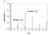
- FIG. 10 is a diagram showing the analysis results of Fourier series expansion of the d-axis magnetic flux waveform when two types of currents are input to the rotating electric machine of this embodiment shown in FIG. 2, and arranging the amplitudes of the harmonic components.
- FIG. 11 is a diagram showing the analysis results of Fourier series expansion of the d-axis current waveform when two types of currents are input to the rotating electric machine of this embodiment shown in FIG. 2, and arranging the amplitudes of the harmonic components.
- the amplitude of the 12th component of the rotating electric machine of Comparative Example 1 shown in FIG. 8 is significantly smaller than the amplitude of the 12th component of the rotating electric machine of this embodiment shown in FIG. 10. Therefore, in the rotating electric machine of Comparative Example 1, there is a large difference between the amplitude of the 12th component of the d-axis magnetic flux when PWM current is input and the amplitude of the 12th component of the d-axis magnetic flux when ideal current is input.
- the difference between the amplitude of the 12th-order component of the d-axis magnetic flux when a PWM current is input and the amplitude of the 12th-order component of the d-axis magnetic flux when an ideal current is input is small.
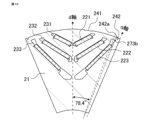
- FIG. 12 is a cross-sectional view of a region of one pole of a rotating electric machine of Comparative Example 2 according to the present embodiment.
- the central angle of the third-layer bridge in the circumferential direction is smaller than that of the rotating electric machine of the present embodiment.
- the electrical angle between the d-axis and a straight line connecting the center of the third-layer bridge and the center of the rotation shaft is set to 78.4°.
- the start point 242a of the second cutout portion is located on the q-axis side of the end point 273b of the third-layer bridge, which is the end point of the third-layer bridge farthest from the d-axis.
- the circumferential region of the second cutout portion 242 is not included in the circumferential region of the third-layer bridge 273.
- FIG. 13 is a diagram showing the relationship between the amplitude difference obtained by subtracting the 12th component amplitude of the d-axis magnetic flux when an ideal current is input from the 12th component amplitude of the d-axis magnetic flux when a PWM current is input in a rotating electric machine according to this embodiment, and the 12th component amplitude of the d-axis current when a PWM current is input.
- FIG. 13 is a diagram showing the relationship between the amplitude difference obtained by subtracting the 12th component amplitude of the d-axis magnetic flux when an ideal current is input from the 12th component amplitude of the d-axis magnetic flux when a PWM current is input in a rotating electric machine according to this embodiment, and the 12th component amplitude of the d-axis current when a PWM current is input.
- the horizontal axis is the amplitude difference obtained by subtracting the 12th component amplitude of the d-axis magnetic flux when an ideal current is input from the 12th component amplitude of the d-axis magnetic flux when a PWM current is input
- the vertical axis is the 12th component amplitude of the d-axis current when a PWM current is input.
- A is the characteristic value of the rotating electric machine according to this embodiment
- B is the rotating electric machine of Comparative Example 1 shown in FIG. 4
- C is the characteristic value of the rotating electric machine of Comparative Example 2 shown in FIG. 12.
- FIG. 14 is a diagram showing the relationship between the amplitude difference obtained by subtracting the 12th component amplitude of the d-axis magnetic flux when an ideal current is input from the 12th component amplitude of the d-axis magnetic flux when a PWM current is input in a rotating electric machine according to this embodiment, and the magnet eddy current loss when a PWM current is input.
- the horizontal axis is the amplitude difference obtained by subtracting the 12th component amplitude of the d-axis magnetic flux when an ideal current is input from the 12th component amplitude of the d-axis magnetic flux when a PWM current is input
- the vertical axis is the magnet eddy current loss when a PWM current is input.
- A is the characteristic value of the rotating electric machine according to this embodiment
- B is the rotating electric machine of Comparative Example 1 shown in FIG. 4
- C is the characteristic value of the rotating electric machine of Comparative Example 2 shown in FIG. 12.
- the magnet eddy current loss in the rotating electric machine of this embodiment is reduced by about 31% compared to the magnet eddy current loss in the rotating electric machine of Comparative Example 1, which does not have the first and second cutouts.
- the magnet eddy current loss can be reduced by reducing the difference between the 12th component amplitude of the d-axis magnetic flux when an ideal current is input and the 12th component amplitude of the d-axis magnetic flux when a PWM current is input.
- the 12th-order component of the d-axis magnetic flux when a PWM current is input does not usually change significantly even if the structure of the first cutout portion 241 and the second cutout portion 242 is changed.
- the 12th-order component of the d-axis magnetic flux when an ideal current is input changes significantly depending on the structure of the first cutout portion 241 and the second cutout portion 242.
- the structure of the first and second cutouts for reducing magnet eddy current loss in the rotating electric machine of this embodiment is described below.
- multiple rotors with different combinations of dimensions of the first and second cutouts were designed, and electromagnetic field analysis was performed when two types of current were input.
- the radial depth of the first and second cutouts was constant, and the radial depth was 1/3 of the gap length between the stator and rotor.
- FIG. 15 shows the difference between the 12th-order amplitude of the d-axis magnetic flux when an ideal current is input and the 12th-order amplitude of the d-axis magnetic flux when a PWM current is input for a structure of the first cutout portion when at least a portion of the circumferential area of the first cutout portion is included in the circumferential area of the first layer bridge.
- the horizontal axis is the electrical angle when the d-axis is set as the reference electrical angle of 0°
- the vertical axis is the difference between the 12th-order amplitude of the d-axis magnetic flux when an ideal current is input and the 12th-order amplitude of the d-axis magnetic flux when a PWM current is input.
- the dashed line indicates the position of the start point of the first cutout portion in electrical angle
- the dashed-dotted line indicates the position of the end point of the first cutout portion in electrical angle.
- Figure 16 shows the difference between the 12th component amplitude of the d-axis magnetic flux when an ideal current is input for the first layer bridge structure and the 12th component amplitude of the d-axis magnetic flux when a PWM current is input.
- the horizontal axis is the electrical angle when the d-axis is set as the reference electrical angle of 0°
- the vertical axis is the difference between the 12th component amplitude of the d-axis magnetic flux when an ideal current is input and the 12th component amplitude of the d-axis magnetic flux when a PWM current is input.
- the dashed line indicates the position of the start point of the first layer bridge in electrical angle
- the dashed-dotted line indicates the position of the end point of the first layer bridge in electrical angle.
- the 12th-order component amplitude of the d-axis magnetic flux when a PWM current is input matches the 12th-order component amplitude of the d-axis magnetic flux when an ideal current is input, and the range in which the difference between the two is zero provides a structure that provides the effect of reducing magnet eddy current loss.
- the effect of reducing magnet eddy current loss is obtained when the first cutout portion is formed in the effective range of electrical angles from 17.6° to 42.4°.
- the effective range of the electrical angle of the first layer bridge which provides the effect of reducing magnet eddy current loss, overlaps partially with the effective range of the first cutout.
- the first cutout is provided in the first layer bridge, which is unlikely to be a path for the magnetic flux that is a source of torque generation crossing the teeth and rotor core.
- the first cutout does not obstruct the magnetic flux that is a source of torque generation, and the effect of torque reduction is unlikely to appear.
- FIG. 17 shows the difference between the 12th-order amplitude of the d-axis magnetic flux when an ideal current is input and the 12th-order amplitude of the d-axis magnetic flux when a PWM current is input for a second cutout structure in which at least a portion of the circumferential area of the second cutout is included in the circumferential area of the second-layer bridge.
- the horizontal axis is the electrical angle when the d-axis is set as the reference electrical angle of 0°
- the vertical axis is the difference between the 12th-order amplitude of the d-axis magnetic flux when an ideal current is input and the 12th-order amplitude of the d-axis magnetic flux when a PWM current is input.
- the dashed line indicates the position of the start point of the second cutout in electrical angle
- the dashed-dotted line indicates the position of the end point of the second cutout in electrical angle.
- Figure 18 shows the difference between the 12th component amplitude of the d-axis magnetic flux when an ideal current is input for the second-layer bridge structure and the 12th component amplitude of the d-axis magnetic flux when a PWM current is input.
- the horizontal axis is the electrical angle when the d-axis is set as the reference electrical angle of 0°
- the vertical axis is the difference between the 12th component amplitude of the d-axis magnetic flux when an ideal current is input and the 12th component amplitude of the d-axis magnetic flux when a PWM current is input.
- the dashed line indicates the position of the start point of the second-layer bridge in electrical angle
- the dashed-dotted line indicates the position of the end point of the second-layer bridge in electrical angle.
- the 12th-order component amplitude of the d-axis magnetic flux when a PWM current is input matches the 12th-order component amplitude of the d-axis magnetic flux when an ideal current is input, and the range in which the difference between the two is zero provides a structure that has the effect of reducing magnet eddy current loss.
- the effect of reducing magnet eddy current loss is obtained when the second cutout portion is formed in the effective range of electrical angles from 52.4° to 71.6°.
- the effective range of the electrical angle of the second-layer bridge which provides the effect of reducing magnet eddy current loss, overlaps partially with the effective range of the second cutout.
- the second cutout is provided in the second-layer bridge, which is unlikely to be a path for the magnetic flux that is a source of torque generation that crosses the teeth and rotor core.
- the second cutout does not obstruct the magnetic flux that is a source of torque generation, and the effect of torque reduction is unlikely to appear.
- FIG. 19 shows the difference between the 12th-order amplitude of the d-axis magnetic flux when an ideal current is input and the 12th-order amplitude of the d-axis magnetic flux when a PWM current is input for a second cutout structure in which at least a portion of the circumferential area of the second cutout is included in the circumferential area of the third-layer bridge.
- the horizontal axis is the electrical angle when the d-axis is set as the reference electrical angle of 0°
- the vertical axis is the difference between the 12th-order amplitude of the d-axis magnetic flux when an ideal current is input and the 12th-order amplitude of the d-axis magnetic flux when a PWM current is input.
- the dashed line indicates the position of the start point of the second cutout in electrical angle
- the dashed-dotted line indicates the position of the end point of the second cutout in electrical angle.
- Figure 20 shows the difference between the 12th component amplitude of the d-axis magnetic flux when an ideal current is input for the third-layer bridge structure and the 12th component amplitude of the d-axis magnetic flux when a PWM current is input.
- the horizontal axis is the electrical angle when the d-axis is set as the reference electrical angle of 0°
- the vertical axis is the difference between the 12th component amplitude of the d-axis magnetic flux when an ideal current is input and the 12th component amplitude of the d-axis magnetic flux when a PWM current is input.
- the dashed line indicates the position of the start point of the third-layer bridge in electrical angle
- the dashed-dotted line indicates the position of the end point of the third-layer bridge in electrical angle.
- the 12th-order component amplitude of the d-axis magnetic flux when a PWM current is input matches the 12th-order component amplitude of the d-axis magnetic flux when an ideal current is input, and the range in which the difference between the two is zero provides a structure that has the effect of reducing magnet eddy current loss.
- the effect of reducing magnet eddy current loss is obtained when the second cutout portion is formed in the effective range of electrical angles 78.8° to 89.7°.
- the effective range of the electrical angle of the third-layer bridge which provides the effect of reducing magnet eddy current loss, overlaps partially with the effective range of the second cutout.
- the second cutout is provided in the third-layer bridge, which is unlikely to be a path for the magnetic flux that is a source of torque generation crossing the teeth and rotor core.
- the second cutout does not obstruct the magnetic flux that is a source of torque generation, and the effect of torque reduction is unlikely to appear.
- Figure 21 shows the difference between the 12th component amplitude of the d-axis magnetic flux when an ideal current is input for the first layer bridge structure and the 12th component amplitude of the d-axis magnetic flux when a PWM current is input.
- the horizontal axis is the electrical angle when the d-axis is set as the reference electrical angle of 0°
- the vertical axis is the difference between the 12th component amplitude of the d-axis magnetic flux when an ideal current is input and the 12th component amplitude of the d-axis magnetic flux when a PWM current is input.
- the solid line indicates the circumferential center position of the first layer bridge in electrical angle.
- the amplitude of the 12th-order component of the d-axis magnetic flux when a PWM current is input matches the amplitude of the 12th-order component of the d-axis magnetic flux when an ideal current is input, and the range in which the difference between the two is zero provides the effect of reducing magnet eddy current loss.
- the effect of reducing magnet eddy current loss is obtained when the central angle in the circumferential direction of the first layer bridge is set within the effective range of electrical angles of 37.0° to 40.4°.
- Figure 22 shows the difference between the 12th component amplitude of the d-axis magnetic flux when an ideal current is input for the second layer bridge structure and the 12th component amplitude of the d-axis magnetic flux when a PWM current is input.
- the horizontal axis is the electrical angle when the d-axis is set as the reference electrical angle of 0°
- the vertical axis is the difference between the 12th component amplitude of the d-axis magnetic flux when an ideal current is input and the 12th component amplitude of the d-axis magnetic flux when a PWM current is input.
- the solid line indicates the circumferential center position of the second layer bridge in electrical angle.
- the 12th-order component amplitude of the d-axis magnetic flux when a PWM current is input matches the 12th-order component amplitude of the d-axis magnetic flux when an ideal current is input, and the range in which the difference between the two is zero provides the effect of reducing magnet eddy current loss.
- the effect of reducing magnet eddy current loss is obtained when the circumferential central angle of the second layer bridge is set within the effective range of electrical angles of 59.2° to 64.8°.
- Figure 23 shows the difference between the 12th component amplitude of the d-axis magnetic flux when an ideal current is input for the third layer bridge structure and the 12th component amplitude of the d-axis magnetic flux when a PWM current is input.
- the horizontal axis is the electrical angle when the d-axis is set as the reference electrical angle of 0°
- the vertical axis is the difference between the 12th component amplitude of the d-axis magnetic flux when an ideal current is input and the 12th component amplitude of the d-axis magnetic flux when a PWM current is input.
- the solid line indicates the circumferential center position of the third layer bridge in electrical angle.
- the 12th-order component amplitude of the d-axis magnetic flux when a PWM current is input matches the 12th-order component amplitude of the d-axis magnetic flux when an ideal current is input, and the range in which the difference between the two is zero provides a structure that has the effect of reducing magnet eddy current loss.
- the effect of reducing magnet eddy current loss is obtained when the circumferential central angle of the third layer bridge is set within the effective range of electrical angles of 78.6° to 84.6°.
- the electrical angle at the circumferential center position of the third layer bridge is 78.4°, which is outside the effective range of electrical angles of 78.6° to 84.6° shown in FIG. 23.
- the 12th-order amplitude of the d-axis magnetic flux when a PWM current is input and the 12th-order amplitude of the d-axis magnetic flux when an ideal current is input be perfectly equal, and that the difference between the two be zero. If the magnet eddy current loss can be reduced to a negligible level, the difference between the 12th-order amplitude of the d-axis magnetic flux when a PWM current is input and the 12th-order amplitude of the d-axis magnetic flux when an ideal current is input does not have to be zero.
- the rotating electric machine of this embodiment is a rotating electric machine having a cylindrical stator having a stator core and a coil to which three-phase AC current is input, and a rotor arranged on the inner diameter side of the stator with a gap between the stator and the rotor, and the rotor has a rotor core having multiple magnet slots and multiple magnets arranged in each of the multiple magnet slots.
- the multiple magnets are arranged in a multi-layer structure of two or more layers in the radial direction to form one pole, and a bridge is formed between the multiple magnet slots and the outer peripheral surface of the rotor core, and the outer peripheral surface of the rotor core has two or more pairs of low permeability sections symmetrical with respect to the d axis per pole, and at least a portion of the circumferential area of all low permeability sections is included in the circumferential area of the bridge.
- the outer circumferential surface of the rotor core has two or more pairs of low permeability sections symmetrical with respect to the d-axis per pole, and at least a portion of the circumferential area of all low permeability sections is included in the circumferential area of the bridge, thereby reducing eddy current loss in the magnets.
- synchronous 15-pulse PWM control is used. Therefore, harmonic components of the d-axis magnetic flux and d-axis voltage caused by PWM control mainly occur at ⁇ 3 orders of pulse number, i.e., 12th and 18th orders.
- the same effect can be obtained by focusing on harmonics other than the 12th or 18th order of the d-axis magnetic flux when an ideal current is input.
- the rotating electric machine of this embodiment has been described using an 8-pole, 48-slot distributed winding embedded magnet rotating electric machine, it may be a rotating electric machine of another configuration.
- it may be a rotating electric machine with a combination of the number of poles and the number of slots other than 8-pole, 48-slot, or it may be a rotating electric machine with concentrated winding instead of distributed winding.
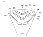
- Fig. 24 is a cross-sectional view of a region of one pole of a rotating electric machine according to embodiment 2.
- Fig. 24 is a cross-sectional view in a direction perpendicular to the rotation axis.
- the entire region of first cutout portion 241 is formed in the region of first layer bridge 271.
- first cutout portion 241 is formed in an effective range of electrical angle 17.6° to 42.4°
- second cutout portion 242 is formed in an effective range of electrical angle 78.8° to 89.7°.
- first cutout 241 and the second cutout 242 are formed within the effective range as described above, even if the entire area of the first cutout 241 is formed in the area of the first layer bridge 271, the 12th order component amplitude of the d-axis magnetic flux when an ideal current is input will be approximately equal to the 12th order component amplitude of the d-axis magnetic flux when a PWM current is input, and magnet eddy current loss can be suppressed.
- the entire area of the first cutout portion 241 is completely contained within the area of the first layer bridge 271, so there is minimal obstruction to the magnetic flux passing between the teeth 12 and the rotor core 21, and the effect of torque reduction is extremely unlikely to appear.
- the entire area of the second cutout portion 242 may be formed in the area of the third layer bridge 273.
- Fig. 25 is a cross-sectional view of a region of one pole of a rotating electric machine according to embodiment 3.
- Fig. 25 is a cross-sectional view in a direction perpendicular to the rotation axis.
- first cutout portion 241 is formed in a range including the entire region of first layer bridge 271.
- first cutout portion 241 is formed in an effective range of electrical angle 17.6° to 42.4°
- second cutout portion 242 is formed in an effective range of electrical angle 78.8° to 89.7°.
- first cutout 241 and the second cutout 242 are formed in the effective range as described above, even if the first cutout 241 is formed in a range including the entire area of the first layer bridge 271, the 12th order component amplitude of the d-axis magnetic flux when an ideal current is input will be approximately equal to the 12th order component amplitude of the d-axis magnetic flux when a PWM current is input, and magnet eddy current loss can be suppressed.
- the second cutout portion 242 may be formed in a range that includes the entire area of the third layer bridge 273.
- FIG. 26 is a cross-sectional view of a region of one pole of a rotating electric machine according to embodiment 4.
- FIG. 26 is a cross-sectional view in a direction perpendicular to the rotation axis.
- the radial depth of the first cutout portion and the second cutout portion is 1/3 of the gap length.
- the radial depth of the first cutout portion 241 extends to the vicinity of the first layer magnet slot 231.
- the first cutout portion 241 is formed in an effective range of an electrical angle of 17.6° to 42.4°
- the second cutout portion 242 is formed in an effective range of an electrical angle of 78.8° to 89.7°.
- first cutout 241 and the second cutout 242 are formed within the effective range as described above, even if the radial depth of the first cutout 241 extends close to the first layer magnet slot 231, the 12th order component amplitude of the d-axis magnetic flux when an ideal current is input is approximately equal to the 12th order component amplitude of the d-axis magnetic flux when a PWM current is input, and magnet eddy current loss can be suppressed.
- the radial depth of the second cutout portion 242 may extend to the vicinity of the third layer magnet slot 233.
- Fig. 27 is a cross-sectional view of a region of one pole of a rotating electric machine according to embodiment 5.
- Fig. 27 is a cross-sectional view in a direction perpendicular to the rotation axis.
- the entire region of first cutout portion 241 is formed in the region of second layer bridge 272.
- first cutout portion 241 is formed in an effective range of electrical angle 52.4° to 71.6°
- second cutout portion 242 is formed in an effective range of electrical angle 78.8° to 89.7°.
- first cutout 241 and the second cutout 242 are formed within the effective range as described above, even if the entire area of the first cutout 241 is formed in the area of the second layer bridge 272, the 12th order component amplitude of the d-axis magnetic flux when an ideal current is input will be approximately equal to the 12th order component amplitude of the d-axis magnetic flux when a PWM current is input, and magnet eddy current loss can be suppressed.
- Fig. 28 is a cross-sectional view of a region of one pole of a rotating electric machine according to embodiment 6.
- Fig. 28 is a cross-sectional view in a direction perpendicular to the rotation axis.
- the entire region of the second cutout portion 242 is formed in the region of the second layer bridge 272.
- the first cutout portion 241 is formed in an effective range of an electrical angle of 17.6° to 42.4°
- the second cutout portion 242 is formed in an effective range of an electrical angle of 52.4° to 71.6°.
- first cutout 241 and the second cutout 242 are formed within the effective range as described above, even if the entire area of the second cutout 242 is formed in the area of the second layer bridge 272, the 12th order component amplitude of the d-axis magnetic flux when an ideal current is input will be approximately equal to the 12th order component amplitude of the d-axis magnetic flux when a PWM current is input, and magnet eddy current loss can be suppressed.
- Embodiment 7 is a cross-sectional view of a region of one pole of a rotating electric machine according to the seventh embodiment.
- FIG. 29 is a cross-sectional view in a direction perpendicular to the rotation axis.
- a part of the first cutout portion 241 is formed in the region of the first-layer bridge 271
- a part of the second cutout portion 242 is formed in the region of the second-layer bridge 272
- a part of the third cutout portion 243 is formed in the region of the third-layer bridge 273.
- the first cutout portion 241 is formed in an effective range of an electrical angle of 17.6° to 42.4°
- the second cutout portion 242 is formed in an effective range of an electrical angle of 52.4° to 71.6°
- the third cutout portion 243 is formed in an effective range of an electrical angle of 78.8° to 89.7°.
- the amplitude of the 12th-order component of the d-axis magnetic flux when an ideal current is input is nearly equal to the amplitude of the 12th-order component of the d-axis magnetic flux when a PWM current is input, making it possible to suppress magnet eddy current loss.
- Fig. 30 is a cross-sectional view of a region of one pole of a rotating electric machine according to embodiment 8.
- Fig. 30 is a cross-sectional view in a direction perpendicular to the rotation axis.
- first cutout portion 241 and second cutout portion 242 are formed in an arc shape.
- first cutout portion 241 is formed in an effective range of electrical angle 17.6° to 42.4°
- second cutout portion 242 is formed in an effective range of electrical angle 78.8° to 89.7°.
- first cutout portion 241 and the second cutout portion 242 are formed within the effective range as described above, even if the first cutout portion 241 and the second cutout portion 242 are formed in an arc shape, the 12th-order component amplitude of the d-axis magnetic flux when an ideal current is input is approximately equal to the 12th-order component amplitude of the d-axis magnetic flux when a PWM current is input, and magnet eddy current loss can be suppressed.
- Embodiment 9. 31 is a cross-sectional view of a region of one pole of a rotating electric machine according to a ninth embodiment.
- FIG. 31 is a cross-sectional view in a direction perpendicular to the rotation axis.
- the first cutout portion and the second cutout portion are filled with a first low permeability member 251 and a second low permeability member 252 having a lower magnetic permeability than the rotor core 21 in the rotating electric machine according to the eighth embodiment in which the first cutout portion and the second cutout portion are formed in an arc shape.
- the first low permeability member 251 and the second low permeability member 252 are the first low permeability portion and the second low permeability portion, respectively.
- the low permeability member a non-magnetic material such as aluminum having a lower magnetic permeability than an electromagnetic steel sheet can be used.
- the first low permeability member 251 is arranged in an effective range of electrical angle 17.6° to 42.4°
- the second low permeability member 252 is arranged in an effective range of electrical angle 78.8° to 89.7°.
- the amplitude of the 12th-order component of the d-axis magnetic flux when an ideal current is input is nearly equal to the amplitude of the 12th-order component of the d-axis magnetic flux when a PWM current is input, making it possible to suppress magnet eddy current loss.
- the first and second cutouts of the rotor core are filled with a low permeability material to form the first and second low permeability parts, respectively.
- the first and second low permeability parts may be formed by applying stress to positions that will become the first and second low permeability parts of a rotor core that does not have the first and second cutouts. Applying stress to a rotor core made of electromagnetic steel plate increases the magnetic resistance of that part. Since the magnetic resistance of the stress application part where stress is applied increases, that part becomes the first and second low permeability part.
- the amplitude of the 12th-order component of the d-axis magnetic flux when an ideal current is input is nearly equal to the amplitude of the 12th-order component of the d-axis magnetic flux when a PWM current is input, making it possible to suppress magnet eddy current loss.
- the outer peripheral surface of the rotor core is flat, reducing noise when the rotor rotates.
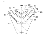
- FIG. 32 is a cross-sectional view of a region of one pole of the rotating electric machine according to the tenth embodiment.
- FIG. 32 is a cross-sectional view in a direction perpendicular to the rotation axis.
- a first through hole 261 and a second through hole 262 are formed axially through the rotor core 21 instead of the first notch portion and the second notch portion in the rotating electric machine according to the second embodiment in which the first notch portion and the second notch portion are formed.
- the first through hole 261 and the second through hole 262 are formed on the inner diameter side of the outer circumferential surface of the rotor core 21.
- the first through hole 261 is formed in an effective range of an electrical angle of 17.6° to 42.4°
- the second through hole 262 is formed in an effective range of an electrical angle of 78.8° to 89.7°. Since the first through hole 261 and the second through hole 262 are spaces, the magnetic permeability of the first through hole 261 and the second through hole 262 is smaller than the magnetic permeability of the rotor core 21. That is, the first through hole 261 and the second through hole 262 become a first low magnetic permeability portion and a second low magnetic permeability portion, respectively.
- the amplitude of the 12th-order component of the d-axis magnetic flux when an ideal current is input is approximately equal to the amplitude of the 12th-order component of the d-axis magnetic flux when a PWM current is input, making it possible to suppress magnet eddy current loss.
- the outer peripheral surface of the rotor core 21 is flat, so noise is reduced when the rotor rotates.
- the structure of the rotating electric machine for reducing magnet eddy current loss is as follows. That is, the rotating electric machine has a structure in which the magnetic resistance changes on the outer circumferential surface of the rotor core, and this structure makes the amplitude of at least one order component among the harmonic components of the d-axis magnetic flux when a current that does not include a carrier harmonic component by PWM control is input equal to the amplitude of the at least one order component among the harmonic components of the d-axis magnetic flux when a current that includes a carrier harmonic component by PWM control is input.
- FIG. 33 is a cross-sectional view of one pole region of the rotating electric machine according to the eleventh embodiment.
- FIG. 33 is a cross-sectional view in a direction perpendicular to the rotation axis.
- the first layer magnet 221, the second layer magnet 222, and the third layer magnet 223, which constitute one pole in three layers, are each composed of one flat magnet.
- the center of the first layer bridge 271 is in the range of electrical angle 37.0° to 40.4°
- the center of the second layer bridge 272 is in the range of electrical angle 59.2° to 64.8°
- the center of the third layer bridge 273 is in the range of electrical angle 78.6° to 84.6°.
- the first cutout portion 241 is formed in the effective range of electrical angle 17.6° to 42.4°
- the second cutout portion 242 is formed in the effective range of electrical angle 78.8° to 89.7°, as in the second embodiment.
- the amplitude of the 12th-order component of the d-axis magnetic flux when an ideal current is input is nearly equal to the amplitude of the 12th-order component of the d-axis magnetic flux when a PWM current is input, making it possible to suppress magnet eddy current loss.
- FIG. 34 is a cross-sectional view of one pole region of the rotating electric machine according to the twelfth embodiment.
- FIG. 34 is a cross-sectional view in a direction perpendicular to the rotation axis.
- the first layer magnet 221, the second layer magnet 222, and the third layer magnet 223, which constitute one pole in three layers, are each composed of one arc-shaped magnet.
- the center of the first layer bridge 271 is in the range of electrical angle 37.0° to 40.4°
- the center of the second layer bridge 272 is in the range of electrical angle 59.2° to 64.8°
- the center of the third layer bridge 273 is in the range of electrical angle 78.6° to 84.6°.
- the first cutout portion 241 is formed in the effective range of electrical angle 17.6° to 42.4°
- the second cutout portion 242 is formed in the effective range of electrical angle 78.8° to 89.7°, as in the second embodiment.
- the amplitude of the 12th-order component of the d-axis magnetic flux when an ideal current is input is nearly equal to the amplitude of the 12th-order component of the d-axis magnetic flux when a PWM current is input, making it possible to suppress magnet eddy current loss.
- FIG. 35 is a cross-sectional view of one pole region of the rotating electric machine according to the thirteenth embodiment.
- FIG. 35 is a cross-sectional view in a direction perpendicular to the rotation axis.
- the first layer magnet 221 is composed of one flat magnet.
- the center of the first layer bridge 271 is in the range of electrical angle 37.0° to 40.4°
- the center of the second layer bridge 272 is in the range of electrical angle 59.2° to 64.8°
- the center of the third layer bridge 273 is in the range of electrical angle 78.6° to 84.6°.
- the first cutout portion 241 is formed in the effective range of electrical angle 17.6° to 42.4°
- the second cutout portion 242 is formed in the effective range of electrical angle 78.8° to 89.7°, as in the second embodiment.
- the amplitude of the 12th-order component of the d-axis magnetic flux when an ideal current is input is nearly equal to the amplitude of the 12th-order component of the d-axis magnetic flux when a PWM current is input, making it possible to suppress magnet eddy current loss.
Landscapes
- Engineering & Computer Science (AREA)
- Power Engineering (AREA)
- Permanent Field Magnets Of Synchronous Machinery (AREA)
Priority Applications (2)
| Application Number | Priority Date | Filing Date | Title |
|---|---|---|---|
| JP2023515730A JP7555483B1 (ja) | 2022-12-16 | 2022-12-16 | 回転電機 |
| PCT/JP2022/046377 WO2024127632A1 (ja) | 2022-12-16 | 2022-12-16 | 回転電機 |
Applications Claiming Priority (1)
| Application Number | Priority Date | Filing Date | Title |
|---|---|---|---|
| PCT/JP2022/046377 WO2024127632A1 (ja) | 2022-12-16 | 2022-12-16 | 回転電機 |
Publications (1)
| Publication Number | Publication Date |
|---|---|
| WO2024127632A1 true WO2024127632A1 (ja) | 2024-06-20 |
Family
ID=91484652
Family Applications (1)
| Application Number | Title | Priority Date | Filing Date |
|---|---|---|---|
| PCT/JP2022/046377 Ceased WO2024127632A1 (ja) | 2022-12-16 | 2022-12-16 | 回転電機 |
Country Status (2)
| Country | Link |
|---|---|
| JP (1) | JP7555483B1 (https=) |
| WO (1) | WO2024127632A1 (https=) |
Citations (3)
| Publication number | Priority date | Publication date | Assignee | Title |
|---|---|---|---|---|
| WO2016021651A1 (ja) * | 2014-08-06 | 2016-02-11 | 日本発條株式会社 | モータ |
| JP2017077090A (ja) * | 2015-10-15 | 2017-04-20 | 日立アプライアンス株式会社 | 永久磁石回転電機および洗濯機 |
| JP2021044857A (ja) * | 2019-09-06 | 2021-03-18 | 日立オートモティブシステムズ株式会社 | 回転電機 |
Family Cites Families (1)
| Publication number | Priority date | Publication date | Assignee | Title |
|---|---|---|---|---|
| JP2021097434A (ja) * | 2019-12-13 | 2021-06-24 | 本田技研工業株式会社 | 回転電機のロータおよび回転電機 |
-
2022
- 2022-12-16 JP JP2023515730A patent/JP7555483B1/ja active Active
- 2022-12-16 WO PCT/JP2022/046377 patent/WO2024127632A1/ja not_active Ceased
Patent Citations (3)
| Publication number | Priority date | Publication date | Assignee | Title |
|---|---|---|---|---|
| WO2016021651A1 (ja) * | 2014-08-06 | 2016-02-11 | 日本発條株式会社 | モータ |
| JP2017077090A (ja) * | 2015-10-15 | 2017-04-20 | 日立アプライアンス株式会社 | 永久磁石回転電機および洗濯機 |
| JP2021044857A (ja) * | 2019-09-06 | 2021-03-18 | 日立オートモティブシステムズ株式会社 | 回転電機 |
Also Published As
| Publication number | Publication date |
|---|---|
| JPWO2024127632A1 (https=) | 2024-06-20 |
| JP7555483B1 (ja) | 2024-09-24 |
Similar Documents
| Publication | Publication Date | Title |
|---|---|---|
| JP4880804B2 (ja) | 同期電動機駆動システム | |
| JP5516739B2 (ja) | 電動機用ロータ | |
| US20090315424A1 (en) | Permanent magnet synchronous machine with shell magnets | |
| KR101025084B1 (ko) | 전동기 및 그 회전자 및 회전자용 자심 | |
| TWI398076B (zh) | 馬達的轉子 | |
| EP3089327B1 (en) | Permanent magnet motor | |
| JP5867626B2 (ja) | ダブルステータ型スイッチトリラクタンス回転機 | |
| US20110169369A1 (en) | Stator for an electric machine | |
| WO2011001533A1 (ja) | 永久磁石型回転電機 | |
| JP2012217249A (ja) | 回転子および永久磁石電動機 | |
| WO2019215853A1 (ja) | 回転電機の回転子構造 | |
| JP5365074B2 (ja) | アキシャルギャップ型回転電機 | |
| JP4984347B2 (ja) | 電動機 | |
| US20190181705A1 (en) | Rotor and method for designing rotor | |
| JP3489215B2 (ja) | 永久磁石式同期電動機 | |
| JP7080416B1 (ja) | 回転子および回転電機 | |
| JP7555483B1 (ja) | 回転電機 | |
| JP2018061379A (ja) | 回転電機 | |
| JP5802487B2 (ja) | 永久磁石式回転電機 | |
| JP2021106474A (ja) | 回転電機の回転子及び回転電機 | |
| WO2021182088A1 (ja) | 永久磁石同期モータ | |
| JP7763974B1 (ja) | 回転電機 | |
| JP7784341B2 (ja) | 回転電機 | |
| CN120090386B (zh) | 基于非对称异形转子拓扑结构的电磁驱动 | |
| JP7651724B2 (ja) | 回転電機の回転子 |
Legal Events
| Date | Code | Title | Description |
|---|---|---|---|
| WWE | Wipo information: entry into national phase |
Ref document number: 2023515730 Country of ref document: JP |
|
| 121 | Ep: the epo has been informed by wipo that ep was designated in this application |
Ref document number: 22968542 Country of ref document: EP Kind code of ref document: A1 |
|
| NENP | Non-entry into the national phase |
Ref country code: DE |
|
| 122 | Ep: pct application non-entry in european phase |
Ref document number: 22968542 Country of ref document: EP Kind code of ref document: A1 |