WO2024122081A1 - プラスチック容器 - Google Patents
プラスチック容器 Download PDFInfo
- Publication number
- WO2024122081A1 WO2024122081A1 PCT/JP2023/016388 JP2023016388W WO2024122081A1 WO 2024122081 A1 WO2024122081 A1 WO 2024122081A1 JP 2023016388 W JP2023016388 W JP 2023016388W WO 2024122081 A1 WO2024122081 A1 WO 2024122081A1
- Authority
- WO
- WIPO (PCT)
- Prior art keywords
- gasket
- protrusion
- mouth
- plastic container
- plug
- Prior art date
- Legal status (The legal status is an assumption and is not a legal conclusion. Google has not performed a legal analysis and makes no representation as to the accuracy of the status listed.)
- Ceased
Links
Images


Classifications
-
- B—PERFORMING OPERATIONS; TRANSPORTING
- B65—CONVEYING; PACKING; STORING; HANDLING THIN OR FILAMENTARY MATERIAL
- B65D—CONTAINERS FOR STORAGE OR TRANSPORT OF ARTICLES OR MATERIALS, e.g. BAGS, BARRELS, BOTTLES, BOXES, CANS, CARTONS, CRATES, DRUMS, JARS, TANKS, HOPPERS, FORWARDING CONTAINERS; ACCESSORIES, CLOSURES, OR FITTINGS THEREFOR; PACKAGING ELEMENTS; PACKAGES
- B65D1/00—Rigid or semi-rigid containers having bodies formed in one piece, e.g. by casting metallic material, by moulding plastics, by blowing vitreous material, by throwing ceramic material, by moulding pulped fibrous material or by deep-drawing operations performed on sheet material
- B65D1/12—Cans, casks, barrels, or drums
- B65D1/14—Cans, casks, barrels, or drums characterised by shape
- B65D1/18—Cans, casks, barrels, or drums characterised by shape of polygonal cross-section
-
- B—PERFORMING OPERATIONS; TRANSPORTING
- B65—CONVEYING; PACKING; STORING; HANDLING THIN OR FILAMENTARY MATERIAL
- B65D—CONTAINERS FOR STORAGE OR TRANSPORT OF ARTICLES OR MATERIALS, e.g. BAGS, BARRELS, BOTTLES, BOXES, CANS, CARTONS, CRATES, DRUMS, JARS, TANKS, HOPPERS, FORWARDING CONTAINERS; ACCESSORIES, CLOSURES, OR FITTINGS THEREFOR; PACKAGING ELEMENTS; PACKAGES
- B65D25/00—Details of other kinds or types of rigid or semi-rigid containers
- B65D25/20—External fittings
-
- B—PERFORMING OPERATIONS; TRANSPORTING
- B65—CONVEYING; PACKING; STORING; HANDLING THIN OR FILAMENTARY MATERIAL
- B65D—CONTAINERS FOR STORAGE OR TRANSPORT OF ARTICLES OR MATERIALS, e.g. BAGS, BARRELS, BOTTLES, BOXES, CANS, CARTONS, CRATES, DRUMS, JARS, TANKS, HOPPERS, FORWARDING CONTAINERS; ACCESSORIES, CLOSURES, OR FITTINGS THEREFOR; PACKAGING ELEMENTS; PACKAGES
- B65D39/00—Closures arranged within necks or pouring openings or in discharge apertures, e.g. stoppers
- B65D39/08—Threaded or like closure members secured by rotation; Bushes therefor
-
- B—PERFORMING OPERATIONS; TRANSPORTING
- B65—CONVEYING; PACKING; STORING; HANDLING THIN OR FILAMENTARY MATERIAL
- B65D—CONTAINERS FOR STORAGE OR TRANSPORT OF ARTICLES OR MATERIALS, e.g. BAGS, BARRELS, BOTTLES, BOXES, CANS, CARTONS, CRATES, DRUMS, JARS, TANKS, HOPPERS, FORWARDING CONTAINERS; ACCESSORIES, CLOSURES, OR FITTINGS THEREFOR; PACKAGING ELEMENTS; PACKAGES
- B65D41/00—Caps, e.g. crown caps or crown seals, i.e. members having parts arranged for engagement with the external periphery of a neck or wall defining a pouring opening or discharge aperture; Protective cap-like covers for closure members, e.g. decorative covers of metal foil or paper
- B65D41/02—Caps or cap-like covers without lines of weakness, tearing strips, tags, or like opening or removal devices
- B65D41/04—Threaded or like caps or cap-like covers secured by rotation
-
- B—PERFORMING OPERATIONS; TRANSPORTING
- B65—CONVEYING; PACKING; STORING; HANDLING THIN OR FILAMENTARY MATERIAL
- B65D—CONTAINERS FOR STORAGE OR TRANSPORT OF ARTICLES OR MATERIALS, e.g. BAGS, BARRELS, BOTTLES, BOXES, CANS, CARTONS, CRATES, DRUMS, JARS, TANKS, HOPPERS, FORWARDING CONTAINERS; ACCESSORIES, CLOSURES, OR FITTINGS THEREFOR; PACKAGING ELEMENTS; PACKAGES
- B65D77/00—Packages formed by enclosing articles or materials in preformed containers, e.g. boxes, cartons, sacks or bags
Definitions
- the present invention relates to a plastic container that is suitable for filling, storing, and transporting solutions such as CMP slurry and meets UN standards.
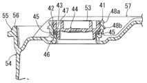
- Patent Document 1 describes a container as follows: "The drum mouth 41 has an internal thread 42 and is threadedly engaged with a plug 44 having an external thread 43. A gasket 45 is disposed below the threads, and a sealing surface is formed by a protruding end face 46 of the drum mouth 41 and a horizontal end face 47 of the plug 44. Two annular protrusions 48a, 48b are formed on the outer periphery of the drum mouth 41. As shown in the cross-sectional view of FIG. 12, a dust-proof gasket 48 is provided.
- the protrusion 48b fits into the protrusion 50 of the dust cap 49 and acts as a retainer, and as shown in the cross-sectional view of FIG. 13, when the safety seal cap 51 is attached, the protrusion 48a fits into the protrusion 52 of the seal cap 51 and acts as a retainer, and as shown in the cross-sectional view of FIG. 11, the upper end surface 53 of the drum mouth 41 is higher than the upper end surface 56 of the L-ring 55 of the resin drum 54, and is lower than the drum top surface 57.
- the mouth of the resin drum is provided with a gasket 45 between the resin drum 54 and the plug 44.
- high-viscosity solutions such as CMP slurry contain fillers with high specific gravity such as abrasives, metal powders, and inorganic fillers, the fillers settle during storage or transportation and the solution cannot be used as is. Therefore, before use, the resin drum is fed to a rotating or vibrating device and rotated or vibrated to uniformly mix the high-viscosity solution before use.
- simply providing the gasket 45 has the disadvantage that the high-viscosity solution leaks out during rotation or vibration.
- the object of the present invention is to provide a plastic container that is lightweight, has excellent cleanliness and resistance to leakage of the contents, and has excellent sealing properties during storage and transportation, and in particular is suitable for filling, storing and transporting high-density, high-viscosity solutions such as CMP slurry, and meets UN standards.
- the first invention of the present application for achieving the above-mentioned object is a plastic container comprising a container body having a mouth formed therein, and a plug for sealing the mouth, wherein a first threaded portion is formed on the inner surface of the mouth, and a second threaded portion capable of being screwed into the first threaded portion is formed on the outer surface of the plug, and a gasket is interposed between the outer surface of the plug and the inner surface of the mouth so as to abut against the outer surface of the plug and the inner surface of the mouth, and wherein a raised portion is formed on the inner surface of the mouth so as to be able to come into contact with the gasket.
- a second aspect of the present invention is a plastic container according to the first aspect of the present invention, characterized in that a protrusion is formed below the second screw portion on the outer surface of the plug.
- a third invention of the present application is a plastic container according to the first invention of the present application, characterized in that a protrusion is formed below the first screw portion on the inner surface of the mouth portion.
- a fourth invention of the present application is a plastic container according to the second invention of the present application, characterized in that a protrusion is formed below the first screw portion on the inner surface of the mouth portion.
- the fifth invention of the present application is a plastic container according to any one of the first to fourth inventions of the present application, characterized in that a groove is formed on the outer surface of the plug and the inner surface of the mouth at the location where the gasket comes into contact.
- a sixth aspect of the present invention is a plastic container according to the fifth aspect of the present invention, characterized in that a protrusion is formed on the inner surface of the mouth at a position where the gasket comes into contact.
- a seventh aspect of the present invention is a plastic container according to the fifth aspect of the present invention, characterized in that a protrusion is formed on the outer surface of the plastic at a location where the gasket comes into contact.
- the eighth invention of the present application is a plastic container according to the sixth invention, characterized in that a protrusion is formed on the outer surface of the plastic at a location where the gasket comes into contact.
- a ninth aspect of the present invention is a plastic container according to the eighth aspect of the present invention, characterized in that the gasket is an O-ring.
- the tenth aspect of the present invention is a plastic container according to the ninth aspect of the present invention, characterized in that the opening is covered with a cap.
- An eleventh aspect of the present invention is a plastic container according to the tenth aspect of the present invention, characterized in that the roundness of the mouth portion is 1.0 mm or less.
- the plastic container of the present invention has the above-mentioned configuration, is lightweight, has high mechanical strength, is highly clean and airtight, has excellent resistance to leakage of the contents, and has excellent sealing properties during storage and transportation, and is particularly suitable for filling, storing, and transporting high-density, high-viscosity solutions such as CMP slurry.
- FIG. 1(A) is a side view showing an example of a plastic container of the present invention
- FIG. 1(B) is a plan view thereof
- FIG. 2 is a cross-sectional view showing an example of the mouth of the plastic container of the present invention
- FIG. 3(A) is a cross-sectional view showing an example of a plug in a plastic container of the present invention
- FIG. 3(B) is a bottom view thereof.
- FIG. 4 is a cross-sectional view showing an example of a plastic container of the present invention with its mouth sealed.
- FIG. 5 is a cross-sectional view showing another example of the state in which the mouth of the plastic container of the present invention is sealed.
- FIG. 6(A) and 6(B) are cross-sectional views showing still another example of the plastic container of the present invention with the mouth part sealed.
- 7A and 7B are diagrams for explaining the gap between the protrusion and the opposing member.
- FIG. 8 is a cross-sectional view showing still another example of the plastic container of the present invention with its mouth portion sealed.
- FIG. 9 is a cross-sectional view showing still another example of the plastic container of the present invention with its mouth portion sealed.
- FIG. 10 is a cross-sectional view showing still another example of the plastic container of the present invention with its mouth portion sealed.
- FIG. 11 is a partial cross-sectional view showing details of a spout portion of a resin drum described in Patent Document 1.
- FIG. 12 is a cross-sectional view showing a state in which a dustproof cap is attached to the mouth plug portion of the resin drum described in Patent Document 1.
- FIG. 13 is a cross-sectional view showing a state in which a safety seal cap is attached to the mouth plug portion of the resin drum described in Patent Document 1.
- the plastic container of the first invention of this application is a plastic container comprising a container body with a mouth formed therein and a plug for sealing the mouth, wherein a first threaded portion is formed on the inner surface of the mouth and a second threaded portion that can be screwed into the first threaded portion is formed on the outer surface of the plug, and a gasket is interposed between the outer surface of the plug and the inner surface of the mouth so as to abut against the outer surface of the plug and the inner surface of the mouth, and wherein a raised portion is formed on the inner surface of the mouth so as to be able to come into contact with the gasket.
- the shape of the plastic container is not particularly limited, but is preferably approximately cylindrical, barrel-shaped, or prismatic.
- the plastic container is preferably made of plastic.
- the above-mentioned plastics can be any known resin that has traditionally been used as a material for liquid containers, such as natural resins, thermoplastic resins, and thermosetting resins.
- thermoplastic resins that have excellent thermoformability, high mechanical strength, and excellent cleanliness are preferred, and among these, olefin-based resins are preferred.
- olefin resins are polymers polymerized using olefin monomers such as ethylene monomers and propylene monomers as the main raw materials.
- ethylene homopolymers such as high-density polyethylene resin, medium-density polyethylene resin, and low-density polyethylene resin
- copolymers of ethylene as the main component with ⁇ -olefins such as propylene, 1-butene, 1-pentene, 1-hexene, and 1-heptene
- propylene homopolymers such as homopolypropylene resin and random polypropylene resin
- copolymers of propylene as the main component with ⁇ -olefins such as ethylene, 1-butene, 1-hexene, and 1-heptene; and the like.
- High-density polyethylene resin, medium-density polyethylene resin, homopolypropylene resin, and random polypropylene resin are preferred, as they provide containers with high mechanical strength and excellent self-supporting properties, and high-density polyethylene resin and polypropylene resin are more preferred.
- these olefin resins may be used alone, or two or more types of olefin resins may be used in combination.
- FIG. 1(A) is a side view showing an example of the plastic container of the present invention
- FIG. 1(B) is a plan view thereof.
- 1 is a barrel-shaped container body consisting of an upper wall portion 2, a side wall portion 3, and a bottom wall portion 4, and a mouth portion 5 and an air port 6 are formed on the upper wall portion 2.
- the air port 6 is an opening connected to a pressurizing device for injecting air so that the pressure inside the container is reduced when the stored liquid is discharged and the discharge speed of the stored liquid does not decrease, or for pressurizing the inside of the container in order to easily discharge the stored liquid.
- the air port 6 is closed during storage and transportation after the container body 1 is filled with the stored liquid.
- multiple air ports 6 may be provided.
- the structure of the air port 6 is not particularly limited, and it may simply be open, be cylindrical, or may have the same shape as the mouth portion in the present invention.
- the method for manufacturing the container body is not particularly limited, but when it is made of an olefin-based resin, it is preferable to mold the olefin-based resin by a blow molding method.
- Any conventionally known blow molding method may be used as the blow molding method, and examples of the method include extrusion blow molding, injection blow molding, stretch blow molding, and multilayer blow molding.
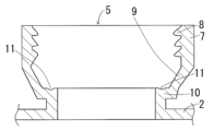
- FIG. 2 is a cross-sectional view showing an example of the mouth 5 formed on the container body 1 of the plastic container.
- the mouth 5 has a cylindrical body 7 located above the upper wall 2 of the container body 1, and can inject and discharge the stored liquid.
- a first screw section 8 is formed near the upper part of the inner surface of the cylindrical body 7, and a substantially flat protrusion 10 is formed at the lower part of the first screw section 8, which protrudes inward in a substantially horizontal direction via a sloped section 9. Furthermore, the tip of the protrusion 10 faces vertically downward, and its lowest end is connected to the upper wall 2 to form the mouth 5.
- a groove 11 with a cross section of a substantially arc shape is formed on the upper surface of the protrusion 10, and part of a gasket, which is an O-ring as described below, can be fitted into the groove 11, which is slightly recessed inward from the upper surface of the protrusion 10.
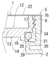
- Fig. 3(A) is a cross-sectional view showing an example of the plug 12 in the plastic container of the present invention
- Fig. 3(B) is a bottom view thereof.
- the plug 12 is composed of a disk-shaped upper member 13 and a disk-shaped lower member 14.
- the diameter of the upper member 13 is longer than that of the lower member 14, and the upper member 13 and the lower member 14 are laminated concentrically and molded as one unit.
- a reinforcing rib is erected on the side of the upper member 13 to form a side wall 15, and the side wall 15 is formed with a second screw portion 16 that can be screwed into the first screw portion 8 formed on the inner surface of the cylindrical body 7.
- a groove 18 with a cross section of an approximately arc shape is formed on the lower surface 17 of the outer peripheral edge of the upper member 13, and a part of a gasket, which is an O-ring, described later, can be fitted into the groove 18, which is slightly recessed inward from the lower surface 17 of the outer peripheral edge.
- Figure 4 is a cross-sectional view showing an example of the state in which the mouth of the plastic container of the present invention is sealed.
- the second screw portion 16 formed on the side wall 15 of the upper member 13 of the plug 12 is screwed into the first screw portion 8 formed on the inner surface of the cylindrical body 7.
- the gasket 21, which is an O-ring abuts against the side surface 20 of the outer wall 19 of the lower member 14 of the plug 12 and the inner surface 9a of the inclined portion 9 of the cylindrical body 7, and a part of the gasket 21, which is an O-ring, fits into the grooves 11 and 18.
- the gasket 21 is clamped and pressed against the outer surface of the plug 12 and the inner surface of the mouth 5 at four points, ensuring excellent sealing of the mouth 5.
- the gasket 21 may be compressed and deformed when clamped and pressed.
- the inner diameter of the gasket 21 is the same as or slightly smaller than the outer diameter of the lower member 14, and the diameter of the gasket 21 is preferably slightly larger than the height of the side surface 20 of the outer wall 19 of the lower member 14, as long as a portion of the gasket 21 can fit into the grooves 11 and 18.
- the cap 22 is a plastic cap that is placed over the sealed mouth portion 5 to protect and strengthen it.
- the cap 22 may have a structure that covers the mouth portion 5 when pressed and adheres closely to the cylindrical body 7 and the inclined portion 9, and if a threaded portion th is formed on the outer surface of the mouth portion 5, the cap 22 may have a structure in which a threaded portion that can be screwed into the threaded portion th is formed on the inner surface of the cap 22.
- the planar shape of the cylindrical body 7 is a perfect circle.
- the circularity of the cylindrical body 7 is high, and more preferably, it is 1.0 mm or less, and even more preferably, it is 0.8 mm or less.
- circularity is the difference between the length of the long axis and the length of the short axis of the top surface of the cylindrical body 7, and is expressed in mm.
- a plastic container When a plastic container is manufactured by blow molding, it becomes an ellipse with the long axis in the parting line (PL) direction, so the length in the PL direction and the direction perpendicular to it can be measured, and the difference between these lengths can be taken as the circularity; the smaller this difference, the higher the circularity.
- the second threaded portion 16 formed on the side wall 15 of the upper member 13 is screwed into the first threaded portion 8 formed on the inner surface of the cylindrical body 7, so the upper member 13 is distorted and must be a perfect circle to ensure airtightness. This can lead to reduced sealing, liquid leakage, or the plug 12 falling off, so it is preferable that the planar shape of the upper member 13 is also a perfect circle. In other words, it is preferable that the roundness of the upper member 13 is high, and more preferably 1.0 mm or less, and even more preferably 0.8 mm or less.
- an O-ring is a solid or hollow ring-shaped body, the cross-sectional shape of which is not particularly limited and may be, for example, circular, elliptical, rectangular, hexagonal, etc., but a circular shape is preferred so that it will not wear down or deform over time. Therefore, the O-ring is preferably a solid or hollow ring-shaped body with a circular cross-sectional shape.
- the hardness (durometer D) of the gasket 21 is preferably 40 to 48. In the present invention, the hardness (durometer D) is a value measured in accordance with JIS K 7215-1986.
- the gasket 21, which is an O-ring, is sandwiched between the upper surface of the protrusion 10 protruding from the inner surface of the cylindrical body 7 and the lower surface 17 of the outer periphery of the upper member 13 of the plug 12 to improve the sealing performance of the container body 1. Therefore, it is preferable that the upper surface of the protrusion 10 and the lower surface 17 of the outer periphery of the upper member 13 are both approximately horizontal and parallel.
- the gasket 21, which is an O-ring, is sandwiched between the upper surface of the protrusion 10 protruding from the inner surface of the cylindrical body 7 and the lower surface 17 of the outer periphery of the upper member 13 of the plug 12.
- the protrusion 10, the upper member 13, and the gasket 21, which is an O-ring are in close contact with each other.
- the surface smoothness of the upper surface of the protrusion 10 and the lower surface 17 of the outer peripheral edge of the upper member 13 is preferably 0.30 mm or less, and more preferably 0.25 mm or less.
- the surface smoothness of the surface of the gasket 21 is also preferably 0.30 mm or less, and more preferably 0.25 mm or less.
- the protrusion 10 on the inner surface of the cylindrical body 7 has the gasket 21, which is an O-ring, positioned on its upper surface, in order to improve sealing performance, it is preferable that the surface smoothness of the upper surface of the protrusion 10 is smaller, preferably 0.20 mm or less, and it is also preferable that the surface smoothness of the upper surface of the protrusion 10 is 0.05 mm or more smaller than the surface smoothness of the lower surface 17 of the outer peripheral edge of the upper member 13 and the surface of the gasket 21.
- the "surface smoothness" in this invention is a value measured using a three-dimensional measuring device (manufactured by Mitutoyo Corporation, product name "Quick Vision PRO").
- a groove (11, 18) with a cross-sectional shape such as an arc shape into which a portion of the gasket 21, which is an O-ring, can be fitted is formed on the upper surface of the protrusion 10 formed on the inner surface of the cylindrical body 7 and/or the lower surface 17 of the outer periphery of the upper member 13 of the plug 12, when the first threaded portion 8 formed on the inner surface of the cylindrical body 7 is screwed into the second threaded portion 16 formed on the side wall 15 of the plug 12, the plug 12 and the gasket 21, which is an O-ring, will adhere more strongly to each other, improving sealing properties, which is preferable.
- a groove having a cross-sectional shape such as an arc shape may be formed on the side surface 20 of the outer peripheral wall 19 of the lower member 14 of the plug 12 into which a portion of the gasket 21, which is an O-ring, can be fitted.
- the material constituting the plug 12 and gasket 21 is preferably an olefin-based resin, more preferably a high-density polyethylene resin or a polypropylene resin, and when the plug 12 and the O-ring gasket 21 are made of an olefin-based resin, they are preferably molded by injection molding.
- Figure 5 is a cross-sectional view showing a different example of the state in which the mouth of the plastic container of the present invention is sealed.
- the second threaded portion 16 formed on the side wall 15 of the upper member 13 of the plug 12 is screwed into the first threaded portion 8 formed on the inner surface of the cylindrical body 7a.
- an upward protrusion 24 is formed concentrically with the cylindrical body 7a, and the cylindrical body 7a reduces in diameter as it goes downward, forming a protrusion 25 that protrudes inward.
- the upward protrusion 24 may be formed on the upper surface of the protrusion 23 in a concentric circle with the cylindrical body 7a and may be positioned upward, but is preferably formed on the upper surface of the protrusion 23 between directly below the center of the gasket 21, which is an O-ring, and the side surface 20 of the outer peripheral wall 19 of the lower member 14.
- the cross-sectional shape of the upward protrusion 24 is not particularly limited, but is preferably a triangle, semicircle, ellipse, or the like.
- the gasket 21, which is an O-ring, and/or the upward protrusion 24 may be compressed and deformed when the gasket 21, which is an O-ring, abuts against the tip of the upward protrusion 24, the raised portion 25, the underside 17 of the outer peripheral edge of the upper member 13, and the side surface 20 of the outer peripheral wall 19 of the lower member 14, thereby being clamped and pressed.
- the gasket 21 which is an O-ring, is clamped and pressed by the underside 17 of the outer periphery of the upper member 13 of the plug 12, the side surface 20 of the outer periphery wall 19 of the lower member 14, and the tip and raised portion 25 of the upward protrusion 24, thereby sealing the mouth 5.
- the surface smoothness of the raised portion 25 is preferably 0.30 mm or less, more preferably 0.25 mm or less, and even more preferably 0.20 mm or less, and the surface smoothness of the raised portion 25 is preferably 0.05 mm or more less than the surface smoothness of the gasket 19, which is an O-ring.
- a protrusion may be formed on one or more of the underside 17 of the outer periphery of the upper member 13, the side surface 20 of the outer periphery wall 19 of the lower member 14, or the raised portion 25. If such a protrusion is formed, the gasket 21, which is an O-ring, is clamped and pressed by more fulcrums, so that it is held more firmly and the container body 1 is more reliably sealed.
- the cross-sectional shape of this protrusion may be the same as the upward protrusion 24.
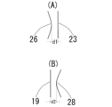
- a raised portion 26 can be provided on the side surface 20a of the outer peripheral wall 19a of the lower member 14, and as shown in FIG. 6(B), a raised portion 28 can be provided on the side surface 27 of the protruding portion 23.
- the plastic container of the present invention has either the raised portion 26 or the raised portion 28, and of course, both the raised portion 26 and the raised portion 28 may be provided on the same plastic container.
- the gap d1 between the tip of the raised portion 26 and the protrusion 23 shown in FIG. 7(A), and the gap d2 between the tip of the raised portion 28 and the outer peripheral wall 19 of the lower member 14 shown in FIG. 7(B) are preferably 1 mm or less, more preferably 0.05 mm or less, with the lower limit of the gaps d1 and d2 being 0.01 mm.
- Figure 8 is a cross-sectional view showing yet another example of the state in which the mouth of the plastic container of the present invention is sealed.
- An upward projection 30 is formed concentrically with the cylindrical body 7b on the upper surface of a substantially flat protrusion 29 that protrudes inwardly in a substantially horizontal direction from the inner surface of the cylindrical body 7b.
- the cross-sectional shape of the upward projection 30 is not particularly limited, but is preferably a triangular, semicircular, elliptical, or other shape.
- a gasket 21, which is an O-ring, is sandwiched between the upward projection 30 and the underside 17 of the outer periphery of the upper member 13 of the plug 12 and the side surface 20 of the outer periphery wall 19 of the lower member 14.
- the gasket 21, which is an O-ring is sandwiched and pressed by the outer periphery 17 of the upper member 13 of the plug 12, the side surface 20 of the outer periphery wall 19 of the lower member 14, and the tip of the upward projection 30, thereby sealing the mouth 5.
- the O-ring gasket 21 and/or the upward protrusion 30 may be compressed and deformed when clamped and pressed by the underside 17 of the outer periphery of the upper member 13 of the plug 12, the side surface 20 of the outer periphery wall 19 of the lower member 14, and the tip of the upward protrusion 30.
- the surface smoothness of the upward projection 30, the underside 17 of the outer peripheral edge of the upper member 13, and the side surface 20 of the outer peripheral wall 19 of the lower member 14 with which the O-ring gasket 21 comes into contact becomes high, the surface pressure applied to the surface of the gasket 21 will not be uniform, decreasing adhesion and decreasing sealing performance, so the surface smoothness of the upward projection 30, the underside 17 of the outer peripheral edge of the upper member 13, and the side surface 20 of the outer peripheral wall 19 of the lower member 14 is preferably 0.30 mm or less, and more preferably 0.25 mm or less.
- the center of the gasket 21, which is an O-ring is located directly above the upward protrusion 30, and the surface smoothness of the upward protrusion 30 is preferably smaller, preferably 0.30 mm or less, more preferably 0.25 mm or less, and even more preferably 0.20 mm or less, and it is preferable that the surface smoothness of the upward protrusion 30 is 0.05 mm or more less than the surface smoothness of the lower surface 17 of the outer peripheral edge of the upper member 13 and the surface of the gasket 21, which is an O-ring.
- Figure 9 is a cross-sectional view showing yet another example of the state in which the mouth of the plastic container of the present invention is sealed.
- An upward protrusion 32 is formed concentrically with the cylindrical body 7c on the upper surface of a substantially flat protrusion 31 that protrudes inwardly in a substantially horizontal direction from the inner surface of the cylindrical body 7c, and a downward protrusion 33 is formed concentrically with the cylindrical body 7c on the lower surface 17 of the outer periphery of the upper member 13 so as to be located directly above the upward protrusion 32.
- the cross-sectional shapes of the upward protrusion 32 and the downward protrusion 33 are not particularly limited, but are preferably triangular, semicircular, elliptical, or the like.
- the gasket 21, which is an O-ring, is sandwiched between the upward protrusion 32 and the downward protrusion 33, and the gasket 21, which is an O-ring, is sandwiched and pressed by the tip of the upward protrusion 32, the tip of the downward protrusion 33, and the side surface 20 of the outer peripheral wall 19 of the lower member 14, thereby sealing the mouth 5.
- the upward protrusion 32 and/or the downward protrusion 33 may be compressed and deformed when clamped and pressed by the tip of the upward protrusion 32, the tip of the downward protrusion 33, and the side surface 20 of the outer peripheral wall 19 of the lower member 14.
- the surface smoothness of the upward projections 32 and downward projections 33 that contact the O-ring gasket 21 becomes too high, the surface pressure applied to the surface of the gasket 21 will not be uniform, reducing adhesion and sealing performance, so the surface smoothness of the upward projections 32 and downward projections 33 is preferably 0.30 mm or less, more preferably 0.25 mm or less, and even more preferably 0.20 mm or less, and the surface smoothness of the upward projections 32 and downward projections 33 is preferably at least 0.05 mm less than the surface smoothness of the surface of the O-ring gasket 21.
- a protrusion may be formed facing inward on the side surface 20 of the outer peripheral wall 19 of the lower member 14 and/or the inner surface 34 of the cylindrical body 7c. If such a protrusion is formed, the gasket 21, which is an O-ring, is clamped and pressed by more fulcrums, so that it is held more firmly and the mouth of the plastic container is more reliably sealed.
- the cross-sectional shape of this protrusion may be the same as the upward protrusion 24.
- FIG. 8 if a protrusion is formed on the inner surface 34 of the cylindrical body 7b so as to protrude inward, by screwing the second screw portion 16 formed on the side wall 15 of the plug 12 into the first screw portion 8 formed on the inner surface of the cylindrical body 7b, the gasket 21, which is an O-ring, will be clamped and pressed at four points: the upward protrusion 30, the side surface 20 of the outer wall 19 of the lower member 14, the underside 17 of the outer edge of the upper member 13, and the above-mentioned protrusion, thereby further improving the sealing of the mouth of the plastic container.
- Fig. 10 is a cross-sectional view showing another example of the state in which the mouth of the plastic container of the present invention is sealed.
- Fig. 10 differs from the structure shown in Fig. 4 in that the upper surface of the protrusion 36 of the cylindrical body 7d, which is a substantially flat plate-like body protruding inwardly in a substantially horizontal direction from the inner surface of the cylindrical body 7d, has a diagonally upward protrusion 37 formed concentrically with the cylindrical body 7d.
- the gasket 21, which is an O-ring is clamped and pressed by the lower surface 17 of the outer peripheral edge of the upper member 13, the side surface 20 of the outer peripheral wall 19 of the lower member 14, the diagonally upward protrusion 37, the protrusion 36, and the inner surface 38 of the cylindrical body 7d, and is firmly held, so that the mouth of the plastic container is sealed more reliably.
- the plastic container of the present invention is preferably provided with an identification information display section on the container wall at a position that can be read from the outside, the identification information being a sheet on which identification information for the materials contained in the container is printed, and the printable and updateable sheet can be attached and peeled off.
- the identification information display section is preferably flat and is preferably located on the top or side wall of the container so that it can be read from the outside of the container wall, and so that it is easy to print and update the identification information of the materials inside the container, and so that the sheet on which the identification information of the materials inside the container is printed can be easily attached and peeled off.
- the top or side wall of a plastic container can be used as it is as the identification information display section, but if the plastic container is transparent, it is difficult to print or update the identification information, and the container may be easily peeled off during transportation and may be difficult to read from the outside.
- the identification information display section is colored, or has a matte finish or corona treatment, and is opaque with unevenness.
- the method for printing and updating the identification information on the identification information display section can be any conventionally known method, and although handwriting is acceptable, it is preferable to use a printing method that can be managed by a computer, such as laser printing or inkjet printing.
- the printing is accompanied by a chemical reaction such as oxidation with the laser, so it is preferable to use an olefin resin, which is more reactive than polyethylene resin, and it is also preferable to add inorganic pigments, organic pigments, inorganic fillers, and other additives that have been commonly used in the manufacture of olefin resin containers to the outer layer.
- a conventionally known adhesive label or adhesive sheet having an adhesive laminated on one side of a paper or plastic sheet is preferably used.
- the identification information display means is preferably a barcode, a two-dimensional code, a QR code (registered trademark), or an RF1D tag.
- the plastic container of the present invention is lightweight, has high mechanical strength, excellent cleanability, and excellent resistance to leakage of the contents and excellent airtightness, making it suitable for use as a container for filling, storing, and transporting beverages and edible liquids such as water, juice, and soy sauce; chemicals such as kerosene, acetic acid, hydrochloric acid, and nitric acid; high-viscosity, high-specific-gravity solutions such as CMP slurries that contain high-specific-gravity fillers such as abrasives, metal powders, and inorganic fillers; and special industrial intermediate chemicals. In particular, it meets the UN standards for transportation and is suitable for use as a transport container for high-viscosity, high-specific-gravity solutions.
Landscapes
- Engineering & Computer Science (AREA)
- Mechanical Engineering (AREA)
- Ceramic Engineering (AREA)
- Closures For Containers (AREA)
- Rigid Containers With Two Or More Constituent Elements (AREA)
- Containers Having Bodies Formed In One Piece (AREA)
Priority Applications (2)
| Application Number | Priority Date | Filing Date | Title |
|---|---|---|---|
| CN202380079284.5A CN120225435A (zh) | 2022-12-09 | 2023-04-26 | 塑料容器 |
| JP2024562568A JP7661639B2 (ja) | 2022-12-09 | 2023-04-26 | プラスチック容器 |
Applications Claiming Priority (4)
| Application Number | Priority Date | Filing Date | Title |
|---|---|---|---|
| JP2022196829 | 2022-12-09 | ||
| JP2022-196829 | 2022-12-09 | ||
| JP2022-196830 | 2022-12-09 | ||
| JP2022196830 | 2022-12-09 |
Publications (1)
| Publication Number | Publication Date |
|---|---|
| WO2024122081A1 true WO2024122081A1 (ja) | 2024-06-13 |
Family
ID=91379113
Family Applications (1)
| Application Number | Title | Priority Date | Filing Date |
|---|---|---|---|
| PCT/JP2023/016388 Ceased WO2024122081A1 (ja) | 2022-12-09 | 2023-04-26 | プラスチック容器 |
Country Status (4)
| Country | Link |
|---|---|
| JP (1) | JP7661639B2 (https=) |
| CN (1) | CN120225435A (https=) |
| TW (1) | TW202423801A (https=) |
| WO (1) | WO2024122081A1 (https=) |
Citations (6)
| Publication number | Priority date | Publication date | Assignee | Title |
|---|---|---|---|---|
| JPH0234454U (https=) * | 1988-08-31 | 1990-03-05 | ||
| JPH0273141U (https=) * | 1988-11-24 | 1990-06-04 | ||
| JPH02105846U (https=) * | 1989-02-09 | 1990-08-22 | ||
| JPH11342962A (ja) * | 1998-06-01 | 1999-12-14 | Kodama Jushi Kogyo Kk | 樹脂ドラムの口栓部 |
| JP2000085830A (ja) * | 1998-09-17 | 2000-03-28 | Kodama Jushi Kogyo Kk | 容器の口栓 |
| JP2009292502A (ja) * | 2008-06-05 | 2009-12-17 | Imotani:Kk | 飲料容器 |
Family Cites Families (1)
| Publication number | Priority date | Publication date | Assignee | Title |
|---|---|---|---|---|
| JP4271835B2 (ja) | 2000-08-18 | 2009-06-03 | アークレイ株式会社 | ピペット装置 |
-
2023
- 2023-04-26 JP JP2024562568A patent/JP7661639B2/ja active Active
- 2023-04-26 WO PCT/JP2023/016388 patent/WO2024122081A1/ja not_active Ceased
- 2023-04-26 TW TW112115453A patent/TW202423801A/zh unknown
- 2023-04-26 CN CN202380079284.5A patent/CN120225435A/zh active Pending
Patent Citations (6)
| Publication number | Priority date | Publication date | Assignee | Title |
|---|---|---|---|---|
| JPH0234454U (https=) * | 1988-08-31 | 1990-03-05 | ||
| JPH0273141U (https=) * | 1988-11-24 | 1990-06-04 | ||
| JPH02105846U (https=) * | 1989-02-09 | 1990-08-22 | ||
| JPH11342962A (ja) * | 1998-06-01 | 1999-12-14 | Kodama Jushi Kogyo Kk | 樹脂ドラムの口栓部 |
| JP2000085830A (ja) * | 1998-09-17 | 2000-03-28 | Kodama Jushi Kogyo Kk | 容器の口栓 |
| JP2009292502A (ja) * | 2008-06-05 | 2009-12-17 | Imotani:Kk | 飲料容器 |
Also Published As
| Publication number | Publication date |
|---|---|
| JPWO2024122081A1 (https=) | 2024-06-13 |
| TW202423801A (zh) | 2024-06-16 |
| CN120225435A (zh) | 2025-06-27 |
| JP7661639B2 (ja) | 2025-04-14 |
Similar Documents
| Publication | Publication Date | Title |
|---|---|---|
| US9650169B2 (en) | Nested blow molded liner and overpack and methods of making same | |
| US7832583B2 (en) | Hot-fillable container and method of making | |
| CN101605699B (zh) | 轻型容器 | |
| CN104114454A (zh) | 基于衬里的运输和分配系统 | |
| US10457438B2 (en) | Multi-functional container base | |
| CN1035171A (zh) | 带阀门的塑料压力容器 | |
| JP7661639B2 (ja) | プラスチック容器 | |
| GB2408259A (en) | Dual closure means for container/storage arrangement | |
| WO2023089507A1 (en) | Assembly of a cup, liner and lid for a paint spray gun | |
| AU2017219006B2 (en) | Multi-fit cap | |
| US20230020391A1 (en) | Hinged Closure Including an Alignment Fin | |
| BR112019018769A2 (pt) | manga de apoio, e, recipiente de aerossol. | |
| CN109689519B (zh) | 液体容器及其防松盖体 | |
| US20180014623A1 (en) | Vial with neck for a liquid product | |
| US20220073230A1 (en) | Blow molded plastic container with integrated spout | |
| CN108860948A (zh) | 一种pe塑料扁瓶 | |
| JP2022026951A (ja) | 科学実験用容器 | |
| CN105129179A (zh) | 具有改进强度的塑料罐和包括该塑料罐的包装系统 | |
| US20250026524A1 (en) | Beverage container structure | |
| CN116997511A (zh) | 树脂容器 | |
| CN119173451A (zh) | 容器盖及结合此的容器组件 | |
| KR200298252Y1 (ko) | 용기 내면에 보강구조를 구비하는 포장용기 | |
| JPH0526361U (ja) | 合成樹脂製ボトル状容器 | |
| WO2004007309A1 (ja) | 密閉容器 | |
| JP2017178363A (ja) | 容器 |
Legal Events
| Date | Code | Title | Description |
|---|---|---|---|
| 121 | Ep: the epo has been informed by wipo that ep was designated in this application |
Ref document number: 23900214 Country of ref document: EP Kind code of ref document: A1 |
|
| WWE | Wipo information: entry into national phase |
Ref document number: 2024562568 Country of ref document: JP |
|
| WWE | Wipo information: entry into national phase |
Ref document number: 202380079284.5 Country of ref document: CN |
|
| WWE | Wipo information: entry into national phase |
Ref document number: 202527059033 Country of ref document: IN |
|
| WWP | Wipo information: published in national office |
Ref document number: 202380079284.5 Country of ref document: CN |
|
| WWP | Wipo information: published in national office |
Ref document number: 202527059033 Country of ref document: IN |
|
| NENP | Non-entry into the national phase |
Ref country code: DE |
|
| 122 | Ep: pct application non-entry in european phase |
Ref document number: 23900214 Country of ref document: EP Kind code of ref document: A1 |