WO2024117192A1 - 検体を撮影した画像の分解能を向上させる画像処理 - Google Patents
検体を撮影した画像の分解能を向上させる画像処理 Download PDFInfo
- Publication number
- WO2024117192A1 WO2024117192A1 PCT/JP2023/042773 JP2023042773W WO2024117192A1 WO 2024117192 A1 WO2024117192 A1 WO 2024117192A1 JP 2023042773 W JP2023042773 W JP 2023042773W WO 2024117192 A1 WO2024117192 A1 WO 2024117192A1
- Authority
- WO
- WIPO (PCT)
- Prior art keywords
- image
- training
- resolution
- image processing
- processing device
- Prior art date
- Legal status (The legal status is an assumption and is not a legal conclusion. Google has not performed a legal analysis and makes no representation as to the accuracy of the status listed.)
- Ceased
Links
Images


Classifications
-
- G—PHYSICS
- G01—MEASURING; TESTING
- G01N—INVESTIGATING OR ANALYSING MATERIALS BY DETERMINING THEIR CHEMICAL OR PHYSICAL PROPERTIES
- G01N33/00—Investigating or analysing materials by specific methods not covered by groups G01N1/00 - G01N31/00
- G01N33/48—Biological material, e.g. blood, urine; Haemocytometers
- G01N33/483—Physical analysis of biological material
-
- G—PHYSICS
- G06—COMPUTING OR CALCULATING; COUNTING
- G06T—IMAGE DATA PROCESSING OR GENERATION, IN GENERAL
- G06T3/00—Geometric image transformations in the plane of the image
- G06T3/40—Scaling of whole images or parts thereof, e.g. expanding or contracting
- G06T3/4046—Scaling of whole images or parts thereof, e.g. expanding or contracting using neural networks
-
- G—PHYSICS
- G06—COMPUTING OR CALCULATING; COUNTING
- G06T—IMAGE DATA PROCESSING OR GENERATION, IN GENERAL
- G06T3/00—Geometric image transformations in the plane of the image
- G06T3/40—Scaling of whole images or parts thereof, e.g. expanding or contracting
- G06T3/4053—Scaling of whole images or parts thereof, e.g. expanding or contracting based on super-resolution, i.e. the output image resolution being higher than the sensor resolution
Definitions
- the present invention relates to an image processing device, an image processing system, an image processing method, a program, and an information recording medium that perform estimation to improve the resolution of an input image of a specimen and obtain an output image.
- a super-resolution technology has been proposed that estimates an output image with improved resolution from an input image.
- estimation is performed based on the features of the object captured in the input image, and a neural network trained by deep learning or the like can be used.
- a photograph of the subject expected to be processed is prepared, and this photograph is processed by adding noise, mosaicking, blurring, reducing the resolution, etc., to serve as an input image for training, and this photograph is often used as the output (correct answer) image for training.
- Tissue specimens are prepared by a procedure of staining with various dyes.
- optical microscopes have a resolution limit caused by the diffraction of light. This limit is called the diffraction limit, and for typical optical systems, it is smaller than biological cells (1 ⁇ m to 100 ⁇ m) but larger than viruses (100 nm), proteins (10 nm), and less complex molecules (1 nm).
- the obtained specimen is immersed in an aldehyde-based fixative to pre-fix the tissue, After washing with rinse solution, Post-fixation was performed using osmium solution. Dehydrate using ethanol, Embedding in epoxy resin, Ultra-thin slices were obtained using an ultramicrotome, diamond knife, etc.
- a tissue specimen is prepared by a procedure involving electronic staining.
- Patent Document 2 machine learning is performed based on images captured using an optical microscope (first microscope) and an electron microscope (second microscope).
- the first microscope captures an image of a cell nucleus A1 in an iPS cell (first region)
- the electron microscope captures an image of a cell nucleus A2 in a brain tissue cell (second region), and different specimens are observed for different regions.
- the wavelengths of the waves also differ, and generally, the shorter the wavelength, the higher the spatial resolution.
- normal light unpolarized waves
- Polarized light polarized waves
- JP 2022-056769 A Patent Publication No. 2021-18582 Patent Publication No. 2022-527642
- specimens for electron microscopes often require more effort, time, and cost to prepare than specimens for light microscopes.
- the use of electron microscopes themselves can also be problematic in terms of effort, time, and cost compared to light microscopes.
- an input image for example, a pathology image based on a photograph of a pathology specimen taken of a specimen for an optical microscope, or an epidermis image of the skin surface of an affected area taken with a digital camera
- an output image for example, an estimated image that shows the results of estimating elements of how the tissue corresponding to the specimen appears as if it were photographed with an electron microscope, or how the affected area appears as if it were photographed with polarized light or light in a specific wavelength band for dermatoscopy
- the present invention aims to solve the above problems by providing an image processing device, an image processing system, an image processing method, a program, and an information recording medium that perform estimation to improve the resolution of an input image of a specimen and obtain an output image.
- the image processing device comprises: When an input image of a target specimen is inputted by a first wave having a first resolution, By providing the input image to a trained super-resolution network, an output image that should be obtained by photographing the target specimen with a second wave having a second resolution is estimated.
- the second resolution is higher than the first resolution.
- the input image may be configured to capture a cross section of the target specimen.
- the super-resolution network includes: A training input based on a first training image obtained by photographing a first training cross section that appears by cutting a training specimen with the first wave motion; A training output based on a second training image obtained by photographing a second training section that appears opposite to the first training section with the second wave motion;
- the method can be configured to be trained using training data including
- the present invention provides an image processing device, an image processing system, an image processing method, a program, and an information recording medium that perform estimation to improve the resolution of an input image of a specimen and obtain an output image.
- FIG. 1 is an explanatory diagram showing a schematic configuration of an image processing device according to an embodiment of the present invention
- FIG. 2 is an explanatory diagram illustrating an example of a super-resolution network used by an image processing device according to an embodiment of the present invention.
- 10 is a flowchart showing a control flow of a training process for training a super-resolution network, which is executed in an image processing device according to an embodiment of the present invention.
- 4 is a flowchart showing a flow of control of image processing executed by the image processing apparatus according to the embodiment of the present invention.
- 1 is an explanatory diagram showing a schematic configuration of an image processing system according to an embodiment of the present invention
- FIG. 1 is an explanatory diagram showing a schematic configuration of an image processing system according to an embodiment of the present invention
- FIG. 1 is an explanatory diagram showing a schematic configuration of an image processing system according to an embodiment of the present invention
- FIG. 1 is an explanatory diagram showing a schematic configuration of an image processing system according to an embodiment
- FIG. 1 is an explanatory diagram showing a schematic configuration of an image processing device according to an embodiment of the present invention
- FIG. 2 is an explanatory diagram showing the configuration of an Encoder in a VAE, which is an example of a generation network in an image processing device according to an embodiment of the present invention.
- FIG. 2 is an explanatory diagram showing the configuration of a decoder in a VAE, which is an example of a generation network in an image processing device according to an embodiment of the present invention.
- FIG. 2 is an explanatory diagram showing the configuration of an Encoder in a VAE, which is another example of a generation network in an image processing device according to an embodiment of the present invention.
- FIG. 2 is an explanatory diagram showing the configuration of a decoder in a VAE, which is another example of a generation network in an image processing device according to an embodiment of the present invention.
- This is a photograph in place of a drawing, which shows a captured pathological image, an electron microscope image estimated from the pathological image, and a generated reference image side by side in grayscale.
- This is a photograph in lieu of a drawing, which shows the captured pathological image, an electron microscope image estimated from the pathological image, and a generated reference image side-by-side in binary monochrome.
- the image processing apparatus is typically realized by a computer executing a program.
- the computer is connected to various output devices and input devices, and transmits and receives information to and from these devices.
- Programs executed by a computer can be distributed or sold by a server to which the computer is connected for communication, or they can be recorded on non-transitory information recording media such as CD-ROM (Compact Disk Read Only Memory), flash memory, or EEPROM (Electrically Erasable Programmable ROM), and then the information recording media can be distributed, sold, etc.
- CD-ROM Compact Disk Read Only Memory
- flash memory or EEPROM (Electrically Erasable Programmable ROM)
- EEPROM Electrical Erasable Programmable ROM
- the program is installed on a non-temporary information recording medium such as a hard disk, solid state drive, flash memory, EEPROM, etc., possessed by the computer.
- the image processing device of this embodiment is then realized by the computer.
- the computer's CPU Central Processing Unit
- RAM Random Access Memory
- OS Operating System
- a computer it is desirable for a computer to be equipped with a GPU (Graphics Processing Unit) in order to perform various image processing calculations at high speed.
- a GPU Graphics Processing Unit
- TensorFlow it becomes possible to utilize the learning and classification functions in various artificial intelligence processes under the control of the CPU.
- an electronic circuit that satisfies the specifications defined in the program is configured using an FPGA (Field Programmable Gate Array) or an ASIC (Application Specific Integrated Circuit), and the electronic circuit functions as a dedicated device that performs the functions defined in the program to realize the image processing device of this embodiment.
- FPGA Field Programmable Gate Array
- ASIC Application Specific Integrated Circuit
- FIG. 1 is an explanatory diagram showing a schematic configuration of an image processing device according to an embodiment of the present invention.
- the image processing device 101 includes an input unit 102 and a super-resolution unit 103.
- an input image of a target specimen captured with a first wave having a first resolution is input to the input unit 102.
- the super-resolution unit 103 provides an input image to the trained super-resolution network 104, causing it to estimate an output image that should be obtained by photographing the target specimen with a second wave having a second resolution.
- Any neural network can be used as the super-resolution network 104.
- a neural network as shown in FIG. 2 may be used, or a complex neural network as shown in Non-Patent Document 2 may be used.
- the second wavelength band of the second wave can be configured to be shorter than the first wavelength band of the first wave.
- first wave to be light and the second wave to be an electron beam.
- the output image to be captured by the electron microscope is estimated from an input image based on a photograph taken by an optical microscope.
- the first wave can be configured to be unpolarized light and the second wave to be polarized light.
- the output image to be captured by the dermatoscope is estimated from an input image based on a photograph taken in normal light.
- the super-resolution network 104 is trained using multiple sets of training data.
- each training data includes a training input (input data) and a training output (correct answer data).
- the training data will be images of the same subject captured in the past using two types of waves.
- the training input is taken from photographs taken in normal light
- the training output is taken from photographs taken in polarized light.
- specimens and samples for observation with an optical microscope and those for observation with an electron microscope are treated differently. As such, it can be difficult to photograph the same object using two types of waves.
- input data based on a first training image obtained by photographing a first training cross section that appears by cutting the training specimen with a first wave motion can be used as the training input
- correct answer data based on a second training image obtained by photographing a second training cross section that appears opposite the first training cross section with a second wave motion can be used as the training output.
- the cross section itself may be significantly deformed due to the cutting. Therefore, after fixing the sample, several thin slices are cut from the original cross section, and the slice of the inner layer (the layer furthest from the original cross section) can be photographed and used as the training input and training output.
- the training input and training output are each images of sections spaced apart from the cut surface of the specimen. Therefore, the physical locations within the specimen of the areas imaged in the training input and training output are not the opposing cross sections themselves, but sections located in the vicinity. However, if the distance between them is small enough, these sections can be treated as essentially opposing cross sections.
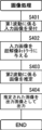
- Fig. 4 is a flowchart showing the flow of control of image processing executed by the image processing device according to the embodiment of the present invention.
- the input unit 102 receives an input of an input image of a target specimen captured with a first wave having a first resolution (step S401).
- the super-resolution unit 103 provides the accepted input image to the super-resolution network 104 (step S402).
- the super-resolution network 104 estimates, based on the input image, an image that should be obtained by photographing the target specimen with a second wave having a second resolution (step S403).
- the image processing device 101 outputs the estimated image as an output image (step S404) and ends this process.
- step S404 control returns to step S401 and the above processing is repeated.
- the training input and training output used in training the super-resolution network are data obtained by photographing opposing cross sections of a single specimen using different wave motions, and when the specimen is cut and prepared into a specimen, deformation of the specimen may occur.
- the image processing device 101 trains the super-resolution network 104 by the following process.
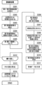
- Figure 3 is a flowchart showing the control flow of the training process for training the super-resolution network executed in the image processing device according to an embodiment of the present invention. The following description will be given with reference to this figure.
- this training process may be executed by the image processing device 101, or may be executed by a device other than the image processing device 101, and the super-resolution network 104 learned by the training process may then be made available to the image processing device 101.
- the image processing device 101 receives a first training image obtained by capturing a first training cross section using a first wave motion, and a second training image obtained by capturing a second training cross section opposite the first training cross section using a second wave motion (step S301).
- the image processing device 101 obtains a mapping that aligns the first training image with the second training image (step S302).
- the first method for finding the mapping is as follows. That is, because the first training image and the second training image have different resolutions, a scale mapping that enlarges or reduces the images to match their resolutions is prepared and applied to the first training image.
- the enlargement or reduction ratio of the scale mapping can be determined based on the shooting conditions when the first training image and the second training image were shot, i.e., the "number of pixels in the width and height of the image" determined by the lens magnification and image resolution, and the "actual width and height of the subject corresponding to one pixel of the image.”
- a transform map is calculated to align the first and second training images after scaling, i.e., the two images now have the same resolution.
- the desired mapping is obtained by combining the scale mapping and the transform mapping.
- the scale mapping can be uniquely determined by calculating the enlargement/reduction ratio based on the conditions under which the first training image and the second training image were captured.
- the transform map can be calculated by applying various techniques for aligning two images with the same resolution, including the technique disclosed in Non-Patent Document 1.
- the second method for finding the mapping is as follows. That is, the combination of feature extraction and convolutional neural networks disclosed in Non-Patent Document 1, and image registration techniques such as reinforcement learning and deep learning that find the direct sum of multiple homography mappings or diffeomorphism mappings can be applied even when the resolutions of the two images do not match. In such cases, the desired mapping can be found by combining the scale mapping and transform mapping into one. Therefore, in such cases, there is no need to find the mapping in two stages, the scale mapping and the transform mapping.
- the image processing device 101 corrects the first training image using the obtained mapping (step S303).
- the image processing device 101 divides the corrected first training image into a plurality of regions (step S304), and repeats the following process for each of the plurality of regions (step S305). Note that, of the plurality of regions, the region that is currently being processed in the repetition will hereinafter be referred to as the "first region.”
- the image processing device 101 cuts out the first region of the corrected first training image to obtain a first partial image (step S306).
- the image processing device 101 determines candidate positions of the area (hereinafter referred to as the "second area") into which the first area is projected in the second training image by the above mapping (step S307).
- the image processing device 101 scans a predetermined scanning range around the candidate position with a window of the same shape as the second region, and obtains an image within the window at each position (step S308).
- the predetermined scanning range is a range centered on the candidate position and shifted up to n pixels up, down, left, and right
- the number of images within the window obtained by scanning will be (2 ⁇ n+1) 2 if the center is included, and (2 ⁇ n) 2 if the center is not included.
- the image processing device 101 calculates the similarity between each of the images within the multiple windows obtained by scanning with the windows and the first partial image, and selects the image with the highest similarity as the second partial image (step S309).
- the position of the second region is identified as the position of the window through which the second partial image is cut out (step S310).
- the image processing device 101 generates training data to be provided to the super-resolution network 104, in which the first partial image is used as a training input and the second partial image is used as a training output (step S311).
- the image processing device 101 After performing this repetitive process for each of the divided regions (step S312), the image processing device 101 removes training data whose similarity is an outlier based on the distribution of similarities between training inputs and training outputs in the generated training data (step S313), and then provides the remaining training data to the super-resolution network 104 to proceed with learning (step S314), and ends this process.
- first training images and second training images are prepared, the above process may be repeated for each pair, or training data may be generated for all pairs and then provided to the super-resolution network 104 all at once to train the super-resolution network 104.
- step S307 candidate positions of the second region relative to the first region are found.
- a value of n that covers a wide range of the second training image or the entire image is used to find the second region, and after the repetition has progressed to a certain extent, the value of n can be reduced after determining candidate positions for the first region based on the correspondence between the positions of the first region and the second region previously identified.
- the resolution of the first training image and the second training image are matched by scale mapping, and then the image processing device 101 performs feature point detection and feature point matching.
- any method can be applied, from classical methods such as SIFT and AKAZE to various methods such as those disclosed in Non-Patent Document 1.
- the desired mapping is one that minimizes the difference between the projections of the first feature points of the multiple pairs obtained here and the second feature points of the multiple pairs. Therefore, the desired mapping can be obtained by solving the minimization problem.
- the image processing device divides the first training image into a number of polygons whose vertices are the feature points detected by feature point detection. Most simply, triangles can be used as the polygons, and Delaunay division can be used as the division.
- Each of the plurality of candidate mappings is (a) projecting a first polygon that is a domain of each of the candidate maps onto a second polygon in a second training image; (b) A mapping that projects the vertices of a first polygon onto the vertices of a second polygon that correspond to the vertices of the first polygon through feature point matching, and can most simply be defined by inversion, translation, rotation, scaling, shearing, trapezoidal transformation, or a combination of these.
- inversion, translation, rotation, scaling, shearing, and combinations thereof can be expressed as affine transformations, and trapezoidal transformations and combinations of the above can be expressed as projective transformations (homography transformations). Any transformation can be specified by a transformation matrix.
- the transformation matrices representing each candidate mapping obtained here should be identical, but in reality, effects such as deformation occur when the samples are created.
- clustering is performed to remove inappropriate candidates from among the multiple candidate mappings.
- each candidate mapping is represented by a transformation matrix, so the difference between the transformation matrices is used as the distance to perform clustering and detect outliers.
- k-NN k-nearest neighbors
- LEF Local Outlier Factor
- the candidate images that belong to the minority cluster i.e., the minority mapping
- the candidate images that belong to the minority cluster are considered to have an incorrect matching between the domain area and the range area, or the domain area or the range area is severely distorted.
- This type of processing makes it possible to obtain appropriate training data that removes the effects of incorrect feature point matching, deformation of parts of the sample, etc.
- the second method for finding the mapping uses image registration techniques such as a combination of feature extraction and a convolutional neural network, and reinforcement learning and deep learning for finding multiple homography mappings and diffeomorphisms. These techniques can be applied even when the resolutions of the two images do not match, but the desired mapping may be obtained by a two-step process in which the resolutions are matched using the scale mapping described above, and then the images are aligned to find a transform mapping.
- the desired mapping cannot be simply described by a single homography matrix, so it is necessary to find the direct sum of multiple homography mappings or a diffeomorphism represented by a displacement vector field.
- Such techniques include a robust alignment technique using agent-based action learning by Julian Krebs et al., the DIRNET technique by Bob D. de Vos et al., and the Quicksilver technique by Xiao Yang et al., and these techniques can be applied to this embodiment.
- the learning of the super-resolution network 104 and the estimation of images by the super-resolution network 104 can be performed in a server computer in which various medical images based on electronic medical records, etc. are collected.
- the server computer can be made to function as the image processing device 101 described above.
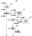
- FIG. 5 is an explanatory diagram showing the general configuration of an image processing system according to an embodiment of the present invention.
- FIG. 6 is an explanatory diagram showing an example of a display on a screen of a terminal computer according to an embodiment of the present invention.
- FIG. 7 is an explanatory diagram showing an example of a display on a screen of a terminal computer according to an embodiment of the present invention.
- the image processing system 201 includes a server computer 202 that realizes the image processing device 101, a terminal computer 203, and a computer communication network 204 that connects the two so that they can communicate with each other.
- the terminal computer 203 includes a first display unit 211, a reception unit 212, a transmission/reception unit 213, and a second display unit 214.
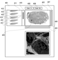
- the first display unit 211 displays, in a first area 411 on the screen 401, a group of images of multiple cross sections that appear when the target specimen is cut into layers.
- each image 412 in the image group is parallel projected from an oblique angle and drawn side by side.
- the original shape of the edges of each image 412 is a rectangle or a square, and when parallel projected from an oblique angle, it becomes a parallelogram, but the edges are not shown in this diagram.
- the first display unit 211 arranges the multiple images included in the image group on multiple parallel planes set in a virtual three-dimensional space in the order in which multiple cross sections for the multiple images are arranged in the target specimen, and depicts the appearance of the virtual three-dimensional space in the first area 411 by parallel (oblique) projection or perspective projection, thereby creating a pseudo three-dimensional feeling.
- the reception unit 212 receives an image selection instruction to select one of the images from the displayed group of images.
- Image selection is performed by selecting the desired image with a mouse, keyboard, etc.
- the edge of image 412 (which, as mentioned above, is originally a square or rectangle, but has been deformed into a parallelogram due to the perspective) is highlighted with dotted line 413 to indicate that the image has been selected.
- a scroll bar 415 can be used to scroll, allowing multiple images that do not fit in the first area 411 to be viewed in sequence. At this time, the image located in the center of the first area 411 may be selected simply by scrolling.
- the selected image is displayed in the second area 422 in its original form as seen normally, not as seen obliquely. That is, in FIG. 6, the portion enclosed by dotted line 413 in the first area 411 corresponds to an oblique projection of the image displayed in the second area 422.
- a three-dimensional animation of the target specimen is displayed in the second area 422.
- the image displayed in the second area 422 can be enlarged or reduced, and a portion of the image selected in the first area 411 can be displayed in the second area 422.
- the area corresponding to that portion can be shown to the observer by being surrounded by a thick line 414 in the first area 411, as shown in FIG. 7. Note that when the entire image is displayed in the second area 422, the thick line 414 is omitted, as shown in FIG. 6.
- the viewer can use the zoom-in button 425 and zoom-out button 426 located near the second area 422 to zoom in or out of the image, and can use the scroll bars 427 and 428 located on the edges of the second area 422 to move the position displayed within the second area 422.
- the reception unit 212 can receive an area selection instruction for selecting an area from the selected image based on the operation of a mouse, keyboard, etc.
- the area of second region 422 surrounded by thick frame 423 is the selected area.
- the image within this area becomes the input image to be processed.
- the position of thick frame 423 can be changed by specifying and dragging within thick frame 423.
- the selected input image is transmitted from the terminal computer 203 to the server computer 202 via the computer communication network 204, either in response to an explicit instruction from the observer or after a certain period of time has elapsed since image and area selection, and is then input to the image processing device 101 as an input image.
- the output image estimated by the image processing device 101 is transmitted from the server computer 202 to the terminal computer 203 via the computer communication network 204.
- the transmission and reception of input images and output images is handled by the transmission and reception unit 213 in the terminal computer.
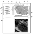
- the second display unit 214 displays the output image estimated by the image processing device 101 in the third area 433 on the screen 401.
- the image group to be estimated is color photographic images of stained specimens taken with an optical microscope, and the estimation results are the results of photographing with an electron microscope.
- the results of photographing with an electron microscope are grayscale images.
- the output image displayed in the third area 433 can be colored.
- the lightness, hue, and saturation of the pixel value displayed for each pixel are respectively set as follows: The brightness of the pixel in the output image corresponding to each pixel in question; the hue of the pixel of the input image corresponding to each pixel; By setting the saturation according to the magnification ratio of the output image for the cross section of the target specimen, it becomes possible to easily grasp the magnification ratio of the output image.
- each institution can use the terminal computer 203 to select a medical image of the target specimen taken with an optical microscope, and if necessary, select a desired area within the image, thereby obtaining an estimate of how the target specimen will look when observed with an electron microscope, which can be useful for diagnosis and research.
- the pathology images and electron microscope images used as training data are scale-mapped to adjust their resolution, and then AKAZE features are detected for the entire image.
- a transform map is then calculated to match each position of the entire electron microscope image, and the entire pathology image is corrected.
- the entire corrected pathology image is slid by 32 pixels to extract a 256x256 pixel pathology tile image.
- Figure 8A is a drawing substitute photograph showing a photographed pathology image, an electron microscope image estimated from the pathology image, and the photographed electron microscope image arranged vertically in grayscale.
- Figure 8B is a drawing substitute photograph showing a photographed pathology image, an electron microscope image estimated from the pathology image, and the photographed electron microscope image arranged vertically in monochrome binary.
- Figure 9A is a drawing substitute photograph showing a photographed pathology image, an electron microscope image estimated from the pathology image, and the photographed electron microscope image arranged vertically in grayscale.
- Figure 9B is a drawing substitute photograph showing a photographed pathology image, an electron microscope image estimated from the pathology image, and the photographed electron microscope image arranged vertically in monochrome binary.
- Figure 10A is a drawing substitute photograph showing a photographed pathology image, an electron microscope image estimated from the pathology image, and the photographed electron microscope image arranged vertically in grayscale.
- Figure 10B is a drawing substitute photograph showing a photographed pathology image, an electron microscope image estimated from the pathology image, and the photographed electron microscope image arranged vertically in monochrome binary.
- the representative photographs of drawings with drawing numbers ending in B are monochrome binarized versions of the representative photographs of drawings with the same drawing numbers and ending in A.
- the drawing substitute photograph of Figure 8B is a monochrome binarized version of the drawing substitute photograph of Figure 8A.
- a pathological image of one cross section of the target specimen taken with an optical microscope at a magnification of 400x; an electron microscope image estimated from the pathological image according to the present embodiment; and a power image of the other cross section of the target specimen taken with an electron microscope at a magnification of 1000 times, the power image being at a position corresponding to the pathological image; are shown side by side, enlarged and reduced for comparison.
- a pathological image is used as an input image
- an electron microscope image is estimated from the input image
- the electron microscope image is output as an output image.
- the output image output here is merely reference information, and is intended to be used for diagnostic support.
- researchers are expected to be the main users of the output image, but it can also be used by clinicians.
- kidney disease is difficult to treat, and once dialysis is initiated, the condition continues for the rest of a patient's life, so treatment must be started early.
- electron microscope images are generated from pathological photographs of the glomeruli taken by the Renal Biomedical Laboratory, making it possible to provide reference information for early diagnosis and early treatment.
- the Renal Biomedical Laboratory itself is often handled by an internist, but may also be handled by a pathologist.
- amyloidosis which affects people all over the world, can be seen in any organ other than the intestine, and there are primary diseases of unknown cause that tend to be regional, and secondary diseases that are caused by decreased renal function and affect dialysis patients.
- the electron microscope images produced by this embodiment can be used as reference information when observing the condition of the affected area.
- the electron microscope image output by this embodiment is generated from a pathology image, so its cost is low. Therefore, by additionally using this electron microscope image as diagnostic support and reference information, it can be useful for low-cost early diagnosis and early treatment.
- an electron microscope image is estimated from a pathological image and used as an output image.
- the output image is quantitatively evaluated for its plausibility and reliability, and the evaluation value is provided to a user of the output image as reference information.
- FIG. 11 is an explanatory diagram showing the general configuration of an image processing device according to an embodiment of the present invention.
- the image processing device 101 in this diagram is obtained by adding a generation unit 502 and an evaluation unit 503 to the image processing device 101 of the above embodiment. The following description will be given with reference to this diagram.
- the generation unit 502 provides the output image output from the super-resolution unit 103 to the trained generation network 505 to generate a reference image.
- the generative network 505 is a network that obtains an output that matches the original input as closely as possible by removing information from the input, such as by reducing the dimensionality of the input or adding noise to the input.
- the simplest generative network 505 is an autoencoder.
- Various autoencoders can be used, such as a stacked autoencoder, a convolutional autoencoder (CAE), a variational autoencoder (VAE), or a conditional variational autoencoder (CVAE).
- CAE convolutional autoencoder
- VAE variational autoencoder
- CVAE conditional variational autoencoder
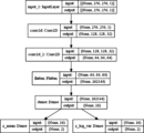
- Fig. 12 is an explanatory diagram showing the configuration of an Encoder in a VAE, which is an example of a generation network in an image processing device according to an embodiment of the present invention.
- Fig. 13 is an explanatory diagram showing the configuration of a Decoder in a VAE, which is an example of a generation network in an image processing device according to an embodiment of the present invention.
- a relatively simple VAE network as shown in this figure can be adopted as the generation network 505.
- Fig. 14 is an explanatory diagram showing the configuration of an Encoder in a VAE, which is another example of a generation network in an image processing device according to an embodiment of the present invention.
- Fig. 14 is an explanatory diagram showing the configuration of an Encoder in a VAE, which is another example of a generation network in an image processing device according to an embodiment of the present invention.
- FIG. 15 is an explanatory diagram showing the configuration of a Decoder in a VAE, which is another example of a generation network in an image processing device according to an embodiment of the present invention.
- a network using a VAE with another configuration as shown in this figure can also be adopted as the generation network 505.
- Neural network based on the diffusion model Generative Adversarial Network (GAN), A neural network based on a flow-based generative model, Various networks can also be used as the generative network 505, such as neural networks that implement dimensionality reduction and restoration based on the Transformer.
- GAN Generative Adversarial Network
- Various networks can also be used as the generative network 505, such as neural networks that implement dimensionality reduction and restoration based on the Transformer.
- the generative network 505 proceeds with learning using a training sample different from the training sample used for learning the super-resolution network 104.
- the generative network 505 proceeds with learning using, as training input and training output, other training images obtained by photographing, with the second wave, other training cross sections that appear by cutting the other training sample.
- the generative network 505 is expected to output an image that closely represents the characteristics that are unique to electron microscopy images.
- the output image output by the super-resolution unit 103 is a plausible image that closely resembles an electron microscope image, the difference between it and the reference image generated by the generation unit 502 will be small, and if the output image output by the super-resolution unit 103 is different from an electron microscope image (for example, an image that contains abnormal information), the difference between the output image and the reference image will be large.
- the evaluation unit 503 quantitatively evaluates the output image numerically based on the difference between the output image and the reference image, and outputs the result.
- the parameter values used for the quantitative evaluation may be as follows: The number of different pixels between the output image and the reference image, or the ratio of the number of different pixels to the total number of pixels. The sum of the different pixel values between the output image and the reference image, or the average of the different pixel values.
- the Mahalanobis distance between the output image and the reference image The Mahalanobis distance between the output image and the reference image. Cosine similarity between the output image and the reference image. The similarity between the output image and the reference image calculated using machine learning and deep learning technologies such as AugNet. The deviation in the distribution of any of the above parameter values; a quantile used in autoregressive models and One Class SVM outlier detection.
- Figure 16 is a photograph in lieu of a drawing that shows a captured pathology image, an electron microscope image estimated from the pathology image, and a generated reference image all arranged in grayscale.
- Figure 17 is a photograph in lieu of a drawing that shows a captured pathology image, an electron microscope image estimated from the pathology image, and a generated reference image all arranged in monochrome binary.
- the central electron microscope image is estimated from the pathology image on the left, and a reference image is generated from the estimated electron microscope image using the VAE disclosed in Figures 12 and 13.
- a plausible electron microscope image is estimated, but in example (b), abnormal shapes (arrows, squares, circles) are drawn, indicating that the generation of the electron microscope image has failed.
- the similarity between the electron microscope image and the reference image calculated by AugNet is 28.441 for example (a) and 34.211 for example (b), meaning that the value is smaller for example (a).
- AugNet's definition of similarity the smaller the value, the more similar the images are, so the difference is smaller in example (a).
- the percentage of similarities below 25 is 100%. 77% were below 27.5; 57% were under 30; 38% had a score of 32.5 or less; 36% were under 35; 18% had a score below 37.5; 0% are below 40; It became.
- the difference and similarity in example (a) were 2,763,465 and 28.517, and the difference and similarity in example (b) were 3,342,139 and 29.369.
- the percentage of images with a total pixel value difference of 1.9 million or less was 100%, 68% have incomes of 2.3 million yen or less; 43% have income of 2.7 million yen or less; 41% have incomes of 3.1 million yen or less; 18% have income of 3.5 million or less; 0% for items below 4 million
- the percentage of similarities below 16 is 92%. 68% were under 20; 50% for those under 24; 43% were under 28; 42% were below 32; 0% below 36 It became.
- a pathology image as an input image to the image processing device 101
- researchers, doctors, etc. can obtain an output image from the image processing device 101 and a quantitative evaluation indicating how likely the output image is as an electron microscope image, and can decide whether or not to use the output image as reference information for diagnostic support.
- the specific generative network and evaluation method are not limited to the above aspects, and various outlier detection and anomaly detection technologies can be applied, and these aspects are also included in the scope of the present invention.
- the image processing device an input unit to which an input image of a target specimen captured with a first wave having a first resolution is input; a super-resolution unit that estimates an output image to be obtained by photographing the target specimen with a second wave having a second resolution by providing the input image to a trained super-resolution network;
- the second resolution is configured to be higher than the first resolution.
- the second waveband of the second vibration may be configured to be shorter than the first waveband of the first vibration.
- the first wave is light
- the second wave may be configured to be an electron beam.
- the first wave is unpolarized light;
- the second wave may be configured to be polarized light.
- the input image may be an image of a cross section of the target specimen.
- the super-resolution network includes: A training input based on a first training image obtained by photographing a first training cross section that appears by cutting a training specimen with the first wave motion; A training output based on a second training image obtained by photographing a second training section that appears opposite to the first training section with the second wave motion;
- the method can be configured to be trained using training data including
- the image processing device includes: correcting the first training image by a mapping that aligns the first training image with the second training image; A first region of the corrected first training image is cut out as a first partial image; Scanning a predetermined scanning range from the second region using a window having the same shape as the second region projected onto the second training image by the mapping of the first region, and determining an image within the scanned window that has the highest similarity to the first partial image as a second partial image;
- the super-resolution network can be configured to be trained by using the first partial image as the training input and the second partial image as the training output.
- a plurality of pairs are obtained, each of the plurality of pairs being: a first feature point detected in the first training image; and second feature points detected in the second training image, the second feature points corresponding to the first feature points; Extract a number of pairs consisting of The mapping is a projection of each of the pairs of first feature points by the mapping; the plurality of pairs of second feature points; It can be constructed such that ⁇ is a mapping that minimizes the difference between ⁇ and ⁇ .
- the alignment Dividing the first training image into a plurality of polygons having vertices that correspond to feature points detected in the first training image by the feature point detection; A plurality of candidate mappings each having a domain defined by each of the plurality of polygons, each of the plurality of candidate mappings comprising: projecting a first polygon that is a domain of each of the candidate maps onto a second polygon in the second training image; determining a plurality of candidate mappings for projecting vertices of the first polygon onto vertices of the second polygon that correspond to the vertices of the first polygon by the feature point matching, respectively; Clustering the plurality of candidate mappings to identify minority mappings that belong to a minority cluster and majority mappings other than the minority cluster; The map is a direct sum of the majority maps, the first sub-image is included in the domain of the mapping; The second partial image may be configured to be included in the range of the mapping.
- the polygon is a triangle
- the partition is a Delaunay partition
- the plurality of candidate mappings may be configured to be inversion, translation, rotation, scaling, shear, trapezoidal, or a combination thereof.
- the mapping can be configured to be a direct sum or a diffeomorphism of multiple homography mappings learned by reinforcement learning or deep learning.
- a generating unit that generates a reference image by providing the output image to a generating network that has been trained by using other training images obtained by cutting other training cross sections that appear by cutting other training specimens and photographing them with the second wave as training inputs and training outputs;
- the image processing device may further include an evaluation unit that quantitatively evaluates the output image based on a difference between the output image and the reference image.
- the generating network comprises: Autoencoders, including Stacked Autoencoders, Convolutional Autoencoders (CAEs), Variational Autoencoders (VAEs), and Conditional Variational Autoencoders (CVAEs), Neural network based on the diffusion model, Generative Adversarial Network (GAN), A neural network based on a flow-based generative model, It can be constructed to be either a Transformer-based neural network.
- Autoencoders including Stacked Autoencoders, Convolutional Autoencoders (CAEs), Variational Autoencoders (VAEs), and Conditional Variational Autoencoders (CVAEs)
- Neural network based on the diffusion model e.g., Generative Adversarial Network (GAN), A neural network based on a flow-based generative model, It can be constructed to be either a Transformer-based neural network.
- the evaluation unit is outlier detection based on the number of different pixels or the distribution of different pixel values between the output image and the reference image (including outlier detection based on an autoregressive model); outlier detection based on One Class SVM of the difference; outlier detection based on a Mahalanobis distance between the output image and the reference image; a cosine similarity between the output image and the reference image;
- the output image may be quantitatively evaluated using any one of AugNet-based similarities between the output image and the reference image.
- the image processing system includes a terminal and the image processing device described above.
- the terminal includes: a first display section for displaying a plurality of images in a first area within a screen; a reception unit for receiving an image selection instruction for selecting one of the displayed images; a transmitting/receiving unit that transmits the selected image to the image processing device as the input image and receives from the image processing device the output image estimated by the image processing device;
- the display device may be configured to include a second display unit that displays the received output image in a second area within the screen.
- the plurality of images may be configured to be a group of images obtained by photographing a plurality of cross sections that appear by cutting the target specimen into layers.
- the second display unit can be configured to use the image within the selected area of the selected image as the input image, and to display the output image obtained for the input image in the second area within the screen.
- the set of images is color images
- the output image is a grayscale image
- the lightness, hue, and saturation of the pixel value displayed on each pixel in the second region are respectively: the brightness of the pixel of the output image corresponding to each pixel; the hue of a pixel of the input image corresponding to each pixel;
- the saturation may be set to a value determined according to a magnification ratio of the output image for the cross section of the target specimen.
- the first display unit is arranging the images included in the image group on a plurality of planes parallel to each other set in a virtual three-dimensional space in an order in which a plurality of cross sections corresponding to the images are arranged in the target specimen;
- the image group can be displayed in the first area by drawing the state of the virtual three-dimensional space in the first area.
- the image processing method includes the steps of: an input step of inputting an input image of a target specimen captured with a first wave having a first resolution; a super-resolution process for estimating an output image to be obtained by photographing the target specimen with a second wave having a second resolution by providing the input image to a trained super-resolution network;
- the second resolution is configured to be higher than the first resolution.
- the program according to the present embodiment causes a computer to: an input unit to which an input image of a target specimen captured with a first wave having a first resolution is input; providing the input image to the trained super-resolution network, thereby causing the network to function as a super-resolution unit that estimates an output image that should be obtained by photographing the target specimen with a second wave having a second resolution;
- the second resolution is configured to be higher than the first resolution.
- the program according to this embodiment can be recorded on a non-transitory computer-readable information recording medium and distributed or sold. It can also be distributed or sold via a temporary transmission medium such as a computer communication network.
- the present invention provides an image processing device, an image processing system, an image processing method, a program, and an information recording medium that perform estimation to improve the resolution of an input image of a specimen and obtain an output image.
Landscapes
- Engineering & Computer Science (AREA)
- Physics & Mathematics (AREA)
- Health & Medical Sciences (AREA)
- Life Sciences & Earth Sciences (AREA)
- General Physics & Mathematics (AREA)
- Biomedical Technology (AREA)
- Chemical & Material Sciences (AREA)
- Theoretical Computer Science (AREA)
- Hematology (AREA)
- Medicinal Chemistry (AREA)
- Evolutionary Computation (AREA)
- Molecular Biology (AREA)
- Urology & Nephrology (AREA)
- Artificial Intelligence (AREA)
- Food Science & Technology (AREA)
- Biophysics (AREA)
- Analytical Chemistry (AREA)
- Biochemistry (AREA)
- General Health & Medical Sciences (AREA)
- Immunology (AREA)
- Pathology (AREA)
- Image Processing (AREA)
Priority Applications (1)
| Application Number | Priority Date | Filing Date | Title |
|---|---|---|---|
| JP2024561545A JP7722757B2 (ja) | 2022-11-30 | 2023-11-29 | 検体を撮影した画像の分解能を向上させる画像処理 |
Applications Claiming Priority (2)
| Application Number | Priority Date | Filing Date | Title |
|---|---|---|---|
| JP2022192062 | 2022-11-30 | ||
| JP2022-192062 | 2022-11-30 |
Publications (1)
| Publication Number | Publication Date |
|---|---|
| WO2024117192A1 true WO2024117192A1 (ja) | 2024-06-06 |
Family
ID=91323884
Family Applications (1)
| Application Number | Title | Priority Date | Filing Date |
|---|---|---|---|
| PCT/JP2023/042773 Ceased WO2024117192A1 (ja) | 2022-11-30 | 2023-11-29 | 検体を撮影した画像の分解能を向上させる画像処理 |
Country Status (2)
| Country | Link |
|---|---|
| JP (1) | JP7722757B2 (https=) |
| WO (1) | WO2024117192A1 (https=) |
Cited By (1)
| Publication number | Priority date | Publication date | Assignee | Title |
|---|---|---|---|---|
| CN118379195A (zh) * | 2024-06-20 | 2024-07-23 | 合肥综合性国家科学中心人工智能研究院(安徽省人工智能实验室) | 基于生成先验的大尺度电子显微镜超分辨率方法 |
Citations (1)
| Publication number | Priority date | Publication date | Assignee | Title |
|---|---|---|---|---|
| JP2022507259A (ja) * | 2018-11-15 | 2022-01-18 | ザ リージェンツ オブ ザ ユニバーシティ オブ カリフォルニア | ホログラフィック顕微鏡画像を様々なモダリティの顕微鏡画像に変換するためのシステムおよび方法 |
-
2023
- 2023-11-29 WO PCT/JP2023/042773 patent/WO2024117192A1/ja not_active Ceased
- 2023-11-29 JP JP2024561545A patent/JP7722757B2/ja active Active
Patent Citations (1)
| Publication number | Priority date | Publication date | Assignee | Title |
|---|---|---|---|---|
| JP2022507259A (ja) * | 2018-11-15 | 2022-01-18 | ザ リージェンツ オブ ザ ユニバーシティ オブ カリフォルニア | ホログラフィック顕微鏡画像を様々なモダリティの顕微鏡画像に変換するためのシステムおよび方法 |
Cited By (1)
| Publication number | Priority date | Publication date | Assignee | Title |
|---|---|---|---|---|
| CN118379195A (zh) * | 2024-06-20 | 2024-07-23 | 合肥综合性国家科学中心人工智能研究院(安徽省人工智能实验室) | 基于生成先验的大尺度电子显微镜超分辨率方法 |
Also Published As
| Publication number | Publication date |
|---|---|
| JP7722757B2 (ja) | 2025-08-13 |
| JPWO2024117192A1 (https=) | 2024-06-06 |
Similar Documents
| Publication | Publication Date | Title |
|---|---|---|
| JP7422825B2 (ja) | 顕微鏡スライド画像のための焦点重み付き機械学習分類器誤り予測 | |
| US9824189B2 (en) | Image processing apparatus, image processing method, image display system, and storage medium | |
| CN112789622B (zh) | 针对生物样本的增强的焦深扩展 | |
| JP6390746B2 (ja) | 診断支援装置、及び診断支援装置における画像処理方法、並びにプログラム | |
| WO2022176396A1 (ja) | 情報処理装置及び情報処理方法、コンピュータプログラム、並びに医療診断システム | |
| Zuo et al. | 4kagent: agentic any image to 4k super-resolution | |
| Thapa et al. | Comparison of super-resolution algorithms applied to retinal images | |
| Gou et al. | Artificial intelligence multiprocessing scheme for pathology images based on transformer for nuclei segmentation | |
| Huang et al. | Deep local-to-global feature learning for medical image super-resolution | |
| Joshi et al. | InterpolAI: deep learning-based optical flow interpolation and restoration of biomedical images for improved 3D tissue mapping | |
| JP7722757B2 (ja) | 検体を撮影した画像の分解能を向上させる画像処理 | |
| Tasdizen et al. | Automatic mosaicking and volume assembly for high-throughput serial-section transmission electron microscopy | |
| KR20240032031A (ko) | 블러 강건성을 제공하도록 전자 이미지를 처리하는 시스템 및 방법 | |
| JP7829048B2 (ja) | デジタル撮像システムおよび方法 | |
| US12488554B2 (en) | System and method for real-time adapitive resolution microscope slide imaging | |
| CN115661377A (zh) | 自监督深度学习及构建各向同性超分辨率三维图像的方法 | |
| Lawson et al. | Immunofluorescence-guided segmentation of three-dimensional features in micro-computed tomography datasets of human lung tissue | |
| JPWO2018128091A1 (ja) | 画像解析プログラム及び画像解析方法 | |
| Kim et al. | Evaluating the robustness of slide-level AI predictions on out-of-focus whole slide images: A retrospective observational study | |
| Wieslander et al. | TEM image restoration from fast image streams | |
| JP7643340B2 (ja) | 画像処理方法、画像処理装置および画像処理システム | |
| Shao et al. | Optimal multiresolution blending of confocal microscope images | |
| Kumar et al. | Enhancement of Low-Quality Images Using Image Super-Resolution | |
| CN120894370B (zh) | 一种共聚焦显微内镜图像的病灶识别方法和装置 | |
| de Haan et al. | Deep learning-based transformation of the H&E stain into special stains |
Legal Events
| Date | Code | Title | Description |
|---|---|---|---|
| 121 | Ep: the epo has been informed by wipo that ep was designated in this application |
Ref document number: 23897838 Country of ref document: EP Kind code of ref document: A1 |
|
| WWE | Wipo information: entry into national phase |
Ref document number: 2024561545 Country of ref document: JP |
|
| NENP | Non-entry into the national phase |
Ref country code: DE |
|
| 122 | Ep: pct application non-entry in european phase |
Ref document number: 23897838 Country of ref document: EP Kind code of ref document: A1 |