WO2024116751A1 - 電力供給システム - Google Patents
電力供給システム Download PDFInfo
- Publication number
- WO2024116751A1 WO2024116751A1 PCT/JP2023/040155 JP2023040155W WO2024116751A1 WO 2024116751 A1 WO2024116751 A1 WO 2024116751A1 JP 2023040155 W JP2023040155 W JP 2023040155W WO 2024116751 A1 WO2024116751 A1 WO 2024116751A1
- Authority
- WO
- WIPO (PCT)
- Prior art keywords
- arc
- power supply
- arc discharge
- conversion device
- unit
- Prior art date
- Legal status (The legal status is an assumption and is not a legal conclusion. Google has not performed a legal analysis and makes no representation as to the accuracy of the status listed.)
- Ceased
Links
Images

Classifications
-
- H—ELECTRICITY
- H02—GENERATION; CONVERSION OR DISTRIBUTION OF ELECTRIC POWER
- H02H—EMERGENCY PROTECTIVE CIRCUIT ARRANGEMENTS
- H02H3/00—Emergency protective circuit arrangements for automatic disconnection directly responsive to an undesired change from normal electric working condition with or without subsequent reconnection ; integrated protection
-
- H—ELECTRICITY
- H02—GENERATION; CONVERSION OR DISTRIBUTION OF ELECTRIC POWER
- H02H—EMERGENCY PROTECTIVE CIRCUIT ARRANGEMENTS
- H02H3/00—Emergency protective circuit arrangements for automatic disconnection directly responsive to an undesired change from normal electric working condition with or without subsequent reconnection ; integrated protection
- H02H3/02—Details
-
- H—ELECTRICITY
- H02—GENERATION; CONVERSION OR DISTRIBUTION OF ELECTRIC POWER
- H02H—EMERGENCY PROTECTIVE CIRCUIT ARRANGEMENTS
- H02H3/00—Emergency protective circuit arrangements for automatic disconnection directly responsive to an undesired change from normal electric working condition with or without subsequent reconnection ; integrated protection
- H02H3/02—Details
- H02H3/05—Details with means for increasing reliability, e.g. redundancy arrangements
-
- H—ELECTRICITY
- H02—GENERATION; CONVERSION OR DISTRIBUTION OF ELECTRIC POWER
- H02J—ELECTRIC POWER NETWORKS; CIRCUIT ARRANGEMENTS OR SYSTEMS FOR SUPPLYING OR DISTRIBUTING ELECTRIC POWER; SYSTEMS FOR STORING ELECTRIC ENERGY
- H02J1/00—Circuit arrangements for DC mains or DC distribution networks
-
- H—ELECTRICITY
- H02—GENERATION; CONVERSION OR DISTRIBUTION OF ELECTRIC POWER
- H02S—GENERATION OF ELECTRIC POWER BY CONVERSION OF INFRARED RADIATION, VISIBLE LIGHT OR ULTRAVIOLET LIGHT, e.g. USING PHOTOVOLTAIC [PV] MODULES
- H02S50/00—Monitoring or testing of PV systems, e.g. load balancing or fault identification
Definitions
- the present invention relates to a power supply system equipped with a power supply module such as a solar cell module and a power conversion device.
- a solar power generation system has been equipped with a solar cell module and a power conversion device, and the direct current power generated by the solar cell module can be converted into alternating current power by the power conversion device and supplied to a commercial power supply system.
- fires can occasionally break out several years after installation. The main cause of such fires is often arc discharge that occurs in areas where cables are pinched during installation, where cables are scratched, or where connectors have poor contact, due to deterioration over time.
- This arc discharge can be roughly classified into series arc discharge and parallel arc discharge depending on the location on the circuit where it occurs.
- a series arc occurs when current passes through a conductor in a series circuit
- a parallel arc occurs when current passes between two conductors connected in parallel in a parallel circuit.
- a series arc discharge can be extinguished by breaking the series circuit
- a parallel arc discharge can be extinguished by shorting the parallel circuit and setting the voltage difference between the ends of the conductors to 0 V.
- the method of response differs depending on the type of arc discharge.
- Patent Document 1 proposes a protection method capable of extinguishing both the series arc discharge and the parallel arc discharge. Specifically, the protection method of Patent Document 1 first executes, when an arc discharge is detected in a solar cell string by an arc detection unit, series arc-extinguishing control in which a series switch cuts off a series circuit that passes current to the solar cell string via a power conversion circuit of a power conditioning system, and parallel arc-extinguishing control in which a parallel switch forms a parallel circuit that passes current to the string without passing through the power conversion circuit.
- the present invention aims to provide a power supply system that can extinguish arc discharges regardless of whether a series arc discharge or a parallel arc discharge occurs in the portion closer to the power supply module than the power conversion device.
- a power supply system having a power supply module, a power conversion device, an arc detection unit, a positive wiring unit, a negative wiring unit, a series arc interruption unit, and a parallel arc short circuit unit
- the power supply module being connected to the power conversion device via the positive wiring unit and the negative wiring unit
- the arc detection unit detecting an arc discharge in a portion closer to the power supply module than the power conversion device
- the series arc interruption unit being capable of interrupting conduction between the power supply module and the power conversion device through the positive wiring unit and the negative wiring unit when the arc detection unit detects an arc discharge
- the parallel arc short circuit unit being connected in parallel with the power conversion device
- the parallel arc short circuit unit providing conduction between the positive wiring unit and the negative wiring unit when the arc detection unit detects an arc discharge after the arc detection unit detects an arc discharge and the series arc interruption unit interrupts the conduction between the power supply module and the power conversion device.
- the arc discharge if the arc discharge is a series arc discharge, it can be extinguished by cutting off the electrical continuity between the power supply module and the power conversion device, and if the arc discharge is a parallel arc discharge, it can be extinguished by short-circuiting the positive wiring section and the negative wiring section.
- the arc discharge can be extinguished whether it is a series arc discharge or a parallel arc discharge.
- the series arc interruption unit provides electrical continuity between the power supply module and the power conversion device when the arc detection unit detects an arc discharge after the arc detection unit detects an arc discharge and the series arc interruption unit interrupts electrical continuity between the power supply module and the power conversion device.
- the parallel arc discharge can be interrupted.
- the arc determination unit is provided which, when the arc detection unit detects an arc discharge and the series arc interruption unit interrupts the electrical continuity between the power supply module and the power conversion device, determines that the arc discharge is a parallel arc discharge.
- One aspect of the present invention is a power supply system that includes a power supply module, a power conversion device, an arc detection unit, a series arc interruption unit, and an arc determination unit, the power supply module is connected in series with the power conversion device via the series arc interruption unit, the arc detection unit detects an arc discharge in a portion closer to the power supply module than the power conversion device, the series arc interruption unit is capable of interrupting conduction between the power supply module and the power conversion device when the arc detection unit detects an arc discharge, and the arc determination unit determines that the arc discharge is a parallel arc discharge when the arc detection unit detects an arc discharge and the arc detection unit detects an arc discharge after the series arc interruption unit interrupts conduction between the power supply module and the power conversion device.
- the power supply system of the present invention can extinguish arc discharge regardless of whether a series arc discharge or a parallel arc discharge occurs in the portion closer to the power supply module than the power conversion device.
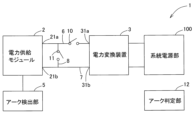
- FIG. 1 is a block diagram of a power supply system according to a first embodiment of the present invention.
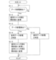
- 2 is a flowchart of an arc interruption operation of the power supply system of FIG. 1 .
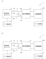
- 3A and 3B are diagrams illustrating the state of a switch unit during an arc interruption operation of the power supply system of FIG. 2, where FIG. 3A is a block diagram illustrating step S1-2 of FIG. 2, and FIG. 3B is a block diagram illustrating step S1-5 of FIG.
- FIG. 11 is a block diagram of a power supply system according to another embodiment of the present invention.
- the power supply system 1 of the first embodiment of the present invention includes, as main components, a power supply module 2, a power conversion device 3, an arc detection unit 5, a positive electrode side wiring unit 6, a negative electrode side wiring unit 7, a detour wiring unit 8, a series switch unit 10 (series arc interruption unit), a parallel switch unit 11 (parallel arc short-circuit unit), and an arc determination unit 12.
- a system power supply unit 100 can be connected to the power conversion device 3.
- the power supply system 1 supplies power generated by a power supply module 2 to a power supply system unit 100 connected to a power conversion device 3 .
- the power supply module 2 is a power generation module that generates electricity using renewable energy, such as a solar cell module or a fuel cell module, or a power storage module, such as a secondary battery, and is capable of supplying the generated electricity to the system power supply unit 100 via the power conversion device 3.
- the power supply module 2 of this embodiment uses a solar cell module that converts light energy into electrical energy.
- the power supply module 2 has a plurality of solar cell groups connected in series or in series and parallel, and each solar cell group has a plurality of solar cells connected in series.
- the power supply module 2 includes a positive terminal 21a connected to the positive electrode side of each solar cell group, and a negative terminal 21b connected to the negative electrode side of each solar cell group.
- the power conversion device 3 converts DC power into AC power, and includes a boost converter section that boosts the power generated by the power supply module 2, and an inverter section that converts the boosted power from DC power to AC power.
- the arc detector 5 is a component that detects an arc discharge when the arc discharge occurs in a portion of the power converter 3 that is closer to the power supply module 2 than the connection terminals 31 a and 31 b . That is, the arc detector 5 detects arc discharge not only in the power supply module 2 but also in wiring members connecting the power supply module 2 to the connection terminals 31a, 31b.
- the positive electrode wiring section 6 is a wiring section that connects the positive electrode terminal 21a of the power supply module 2 and the positive electrode connection terminal 31a of the power conversion device 3, as shown in FIG.
- the negative wiring section 7 is a wiring section that connects the negative terminal 21 b of the power supply module 2 and the negative connection terminal 31 b of the power conversion device 3 .
- the detour wiring section 8 is a wiring section that connects a midpoint of the positive electrode side wiring section 6 and a midpoint of the negative electrode side wiring section 7, and is a wiring section that detours around the power conversion device 3 when viewed from the power supply module 2 side.
- the series switch unit 10 is provided midway through the positive electrode side wiring unit 6, and is a series arc interrupter that interrupts conduction between the power supply module 2 and the power conversion device 3 when a series arc discharge occurs.
- the series switch section 10 can be in a closed state to establish electrical continuity between the power supply module 2 and the power conversion device 3, and in an open state to interrupt electrical continuity between the power supply module 2 and the power conversion device 3.
- the parallel switch section 11 is provided midway through the bypass wiring section 8, and is a parallel arc short-circuit section that, in the event of a parallel arc discharge, connects the positive electrode side wiring section 6 and the negative electrode side wiring section 7 to each other, thereby short-circuiting between the power supply module 2 and the power conversion device 3.
- the parallel switch unit 11 can be closed to electrically connect the positive electrode side wiring unit 6 and the negative electrode side wiring unit 7 to each other, thereby shorting them, and can be opened to cut off electrical continuity between the positive electrode side wiring unit 6 and the negative electrode side wiring unit 7.
- the arc determination unit 12 is a component that, when an arc discharge occurs, determines whether the generated arc discharge is a series arc discharge or a parallel arc discharge.
- the arc interruption operation is performed in parallel with a normal operation in which the power generated by the power supply module 2 is supplied to the system power supply unit 100 via the power conversion device 3 . That is, the arc interruption operation is performed in principle based on the normal operating state, that is, the state in which the series switch section 10 is closed and the parallel switch section 11 is open as shown in FIG.
- step S1-1 when the arc detection unit 5 detects an arc discharge (step S1-1), as shown in FIG. 3(a), the parallel switch unit 11 is kept open while the series switch unit 10 is switched from the closed state to the open state (step S1-2), and it is determined whether the arc detection unit 5 continues to detect the arc discharge (step S1-3).
- step S1-3 if the arc detection unit 5 continues to detect the arc discharge (Yes in step S1-3), the arc determination unit 12 determines that the arc discharge is a parallel arc discharge (step S1-4), and changes the series switch unit 10 from an open state to a closed state, as shown in FIG. 3(b), and changes the parallel switch unit 11 from an open state to a closed state (step S1-5).
- the power supply module 2, the series switch unit 10, and the parallel switch unit 11 form a closed circuit that does not pass through the power conversion device 3, and the positive electrode side wiring unit 6 and the negative electrode side wiring unit 7 are short-circuited by the bypass wiring unit 8 and become the same potential (0 V), so that the parallel arc discharge generated in the power supply module 2 is extinguished.
- step S1-6 determines that the arc discharge is a series arc discharge (step S1-6) and maintains the current state. That is, as shown in FIG. 3(a), the parallel switch unit 11 is maintained in the open state, and the series switch unit 10 is maintained in the open state.
- the parallel switch unit 11 brings the positive electrode side wiring unit 6 and the negative electrode side wiring unit 7 into conduction. Therefore, when the arc discharge is a series arc discharge, the arc can be extinguished by cutting off the continuity between the power supply module 2 and the power conversion device 3, and when the arc discharge is a parallel arc discharge, the arc can be extinguished by short-circuiting the positive electrode side wiring unit 6 and the negative electrode side wiring unit 7.
- the arc discharge can be extinguished whether the arc discharge is a series arc discharge or a parallel arc discharge.
- a series arc discharge can be extinguished when determining whether an arc discharge has occurred. Therefore, it is not necessary to perform a separate arc-extinguishing operation after determining that a series arc discharge has occurred, and it is possible to quickly determine whether an arc is a series arc or a parallel arc and take measures to cut off the arc.
- the series switch section 10 by opening the series switch section 10, it is possible to determine whether or not a series arc discharge has occurred, which allows for greater freedom in the position of the bypass wiring section 8 and improves design efficiency.
- the algorithm for determining whether a parallel arc discharge or a series arc discharge is capable of being updated and simplified, and by reducing the scale of the program, it is possible to improve software reliability and development efficiency.
- the connection position between the bypass wiring section 8 and the positive electrode side wiring section 6 is downstream in the direction of electrical flow of the positive electrode side wiring section 6, and after the arc detection section 5 detects an arc discharge and the series switch section 10 cuts off electrical continuity between the power supply module 2 and the power conversion device 3, if the arc detection section 5 detects an arc discharge, electrical continuity is established between the power supply module 2 and the power conversion device 3. Therefore, even if a parallel arc discharge occurs between the series switch section 10 and the power conversion device 3, the parallel arc discharge can be cut off.
- the parallel switch unit 11 is provided midway through the bypass wiring unit 8, and together with the power supply module 2 and the series switch unit 10, forms a bypass circuit that does not pass through the power conversion device 3. Therefore, when the arc detection unit 5 detects an arc discharge and cuts off the continuity between the power supply module 2 and the power conversion device 3, the series switch unit 10 establishes continuity between the power supply module 2 and the power conversion device 3, and the parallel switch unit 11 shorts out the positive wiring unit 6 and the negative wiring unit 7.
- the power supply system 1 of this embodiment includes an arc determination unit 12 that determines that an arc discharge is a parallel arc discharge when the arc detection unit 5 detects an arc discharge after the series switch unit 10 cuts off the electrical continuity between the power supply module 2 and the power conversion device 3. This makes it easy to respond to an arc discharge because it can quickly determine whether the arc discharge is a series arc discharge or a parallel arc discharge.
- the series switch unit 10 is provided closer to the power supply module 2 than the bypass wiring unit 8, but the present invention is not limited to this. As shown in FIG. 4, the series switch unit 10 may be provided closer to the power conversion device 3 than the bypass wiring unit 8. In other words, the series switch unit 10 may be provided downstream of the bypass wiring unit 8 in the direction of electrical flow of the positive electrode side wiring unit 6. In this case, in step S1-5 of the arc interruption operation in FIG. 2, the series switch unit 10 may be kept open, and the parallel switch unit 11 may be changed to a closed state.
- the power supply system 1 is described as having one power supply module 2, but the present invention is not limited to this.
- the power supply system 1 may have two or more power supply modules 2.
- the series switch section 10 is provided only in the positive electrode wiring section 6, but the present invention is not limited to this.
- the series switch section 10 may also be provided in the negative electrode wiring section 7.
- an arc determination unit 12 is provided to determine whether the arc discharge is a series arc discharge or a parallel arc discharge, but the present invention is not limited to this.
- the arc determination unit 12 may be omitted.
Landscapes
- Engineering & Computer Science (AREA)
- Power Engineering (AREA)
- Protection Of Static Devices (AREA)
Abstract
本発明は、電力変換装置よりも電力供給モジュール側の部分で直列アーク放電と並列アーク放電のいずれが発生したときでもアーク放電を消弧できる電力供給システムを提供する。 電力供給モジュールと、電力変換装置と、アーク検出部と、正極側配線部と、負極側配線部と、直列アーク遮断部と、並列アーク短絡部を有し、電力供給モジュールは、正極側配線部及び負極側配線部を介して電力変換装置に接続され、アーク検出部は、電力変換装置よりも電力供給モジュール側の部分のアーク放電を検出するものであり、並列アーク短絡部は、電力変換装置と並列接続されており、並列アーク短絡部は、アーク放電を検出し直列アーク遮断部が電力供給モジュールと電力変換装置の間の導通を遮断した後に、アーク検出部がアーク放電を検出する場合に、正極側配線部と負極側配線部を導通させる構成とする。
Description
本発明は、太陽電池モジュール等の電力供給モジュールと電力変換装置を備えた電力供給システムに関する。
従来から、太陽光発電システムでは、太陽電池モジュールと、電力変換装置を備え、太陽電池モジュールで発電した直流電力を電力変換装置で交流電力に変換して商用電源系統に供給することが可能となっている。
従来の太陽光発電システムでは、設置後、数年経過した後に、まれに火災が発生する場合がある。このような火災は、施工時のケーブル挟み込みや、ケーブルへの傷、コネクタ部の接触不良がそのまま放置され、経年劣化に伴ってそれらの箇所で発生するアーク放電が主たる原因であることが多い。
従来の太陽光発電システムでは、設置後、数年経過した後に、まれに火災が発生する場合がある。このような火災は、施工時のケーブル挟み込みや、ケーブルへの傷、コネクタ部の接触不良がそのまま放置され、経年劣化に伴ってそれらの箇所で発生するアーク放電が主たる原因であることが多い。
このアーク放電は、回路上発生する場所によって大別すると、直列アーク放電と、並列アーク放電に分類できる。
直列アーク放電は、電流が直列回路内において導線内を通過する場合に発生するものであり、並列アーク放電は、電流が並列回路内において並列接続された2つの導線の間を通過する場合に発生するものである。
直列アーク放電は、直列回路を遮断することで消弧可能であるのに対して、並列アーク放電は、並列回路を短絡させ、導線の端部間の電圧差を0Vにすることで消弧可能であり、アーク放電の種類によって対応方法が異なる。
そのため、従来は、アーク放電を消弧するには、アーク放電が直列アーク放電であるか並列アーク放電であるかを特定した後に、特定したアーク放電に対応する方法で消弧する必要があり、アーク放電に対する対応が遅れる問題があった。
直列アーク放電は、電流が直列回路内において導線内を通過する場合に発生するものであり、並列アーク放電は、電流が並列回路内において並列接続された2つの導線の間を通過する場合に発生するものである。
直列アーク放電は、直列回路を遮断することで消弧可能であるのに対して、並列アーク放電は、並列回路を短絡させ、導線の端部間の電圧差を0Vにすることで消弧可能であり、アーク放電の種類によって対応方法が異なる。
そのため、従来は、アーク放電を消弧するには、アーク放電が直列アーク放電であるか並列アーク放電であるかを特定した後に、特定したアーク放電に対応する方法で消弧する必要があり、アーク放電に対する対応が遅れる問題があった。
そこで、特許文献1では、直列アーク放電と並列アーク放電の双方のアーク放電を消弧できる保護方法が提案されている。
具体的には、特許文献1の保護方法は、まず、太陽電池ストリングにおいてアーク検出部によりアーク放電が検出された場合に、直列スイッチによりパワーコンディショニングシステムの電力変換回路を経て太陽電池ストリングに電流を流す直列電路を遮断する直列消弧制御と、並列スイッチにより前記電力変換回路を経ずにストリングに電流を流す並列電路を形成する並列消弧制御と、を実行する。
この直列消弧制御及び並列消弧制御の後、直列スイッチにより直列電路が遮断され、並列スイッチにより並列電路が形成された状態にて、アーク検出部によりアーク放電が検出された場合に太陽電池ストリングにおける直列アーク放電の発生を検出し、直列消弧制御及び並列消弧制御の後、直列スイッチ及び並列スイッチにより直列電路及び並列電路の両方が遮断された状態にて、アーク検出部によりアーク放電が検出された場合に太陽電池ストリングにおける並列アーク放電の発生を検出する。
そして、太陽電池ストリングにおける直列アーク放電が検出された場合には並列スイッチにより並列電路を遮断し、太陽電池ストリングにおける並列アーク放電が検出された場合には並列スイッチにより並列電路を導通させる。
具体的には、特許文献1の保護方法は、まず、太陽電池ストリングにおいてアーク検出部によりアーク放電が検出された場合に、直列スイッチによりパワーコンディショニングシステムの電力変換回路を経て太陽電池ストリングに電流を流す直列電路を遮断する直列消弧制御と、並列スイッチにより前記電力変換回路を経ずにストリングに電流を流す並列電路を形成する並列消弧制御と、を実行する。
この直列消弧制御及び並列消弧制御の後、直列スイッチにより直列電路が遮断され、並列スイッチにより並列電路が形成された状態にて、アーク検出部によりアーク放電が検出された場合に太陽電池ストリングにおける直列アーク放電の発生を検出し、直列消弧制御及び並列消弧制御の後、直列スイッチ及び並列スイッチにより直列電路及び並列電路の両方が遮断された状態にて、アーク検出部によりアーク放電が検出された場合に太陽電池ストリングにおける並列アーク放電の発生を検出する。
そして、太陽電池ストリングにおける直列アーク放電が検出された場合には並列スイッチにより並列電路を遮断し、太陽電池ストリングにおける並列アーク放電が検出された場合には並列スイッチにより並列電路を導通させる。
しかしながら、特許文献1の保護方法では、直列消弧制御と並列消弧制御の双方を同時に実施するために、直列電路を導通及び遮断する直列スイッチよりも太陽電池ストリング側に、並列電路を導通及び遮断する並列スイッチを設ける必要があり、設計上の自由度が小さく、直列スイッチよりも電力変換回路側で並列アーク放電が発生した場合に、並列アーク放電を消弧できない問題がある。
また、特許文献1の保護方法では、並列アーク放電と直列アーク放電の判断方法が複雑になっていることから、アーク放電を消弧するのに時間がかかり、火災リスクが大きくなる問題がある。
このように、特許文献1の保護方法は更なる改善の余地があった。
また、特許文献1の保護方法では、並列アーク放電と直列アーク放電の判断方法が複雑になっていることから、アーク放電を消弧するのに時間がかかり、火災リスクが大きくなる問題がある。
このように、特許文献1の保護方法は更なる改善の余地があった。
そこで、本発明は、電力変換装置よりも電力供給モジュール側の部分で直列アーク放電と並列アーク放電のいずれが発生したときでもアーク放電を消弧できる電力供給システムを提供することを課題とする。
上記した課題を解決するための本発明の一つの様相は、電力供給モジュールと、電力変換装置と、アーク検出部と、正極側配線部と、負極側配線部と、直列アーク遮断部と、並列アーク短絡部を有し、前記電力供給モジュールは、前記正極側配線部及び前記負極側配線部を介して前記電力変換装置に接続されており、前記アーク検出部は、前記電力変換装置よりも前記電力供給モジュール側の部分のアーク放電を検出するものであり、前記直列アーク遮断部は、前記アーク検出部がアーク放電を検出したときに、前記正極側配線部及び前記負極側配線部による前記電力供給モジュールと前記電力変換装置間の導通を遮断可能であり、前記並列アーク短絡部は、前記電力変換装置と並列接続されており、前記並列アーク短絡部は、前記アーク検出部がアーク放電を検出し前記直列アーク遮断部が前記電力供給モジュールと前記電力変換装置の間の導通を遮断した後に、前記アーク検出部がアーク放電を検出する場合に、前記正極側配線部と前記負極側配線部を導通させる、電力供給システムである。
本様相によれば、アーク放電が直列アーク放電の場合には、電力供給モジュールと電力変換装置の間の導通を遮断することで消弧でき、アーク放電が並列アーク放電の場合には、正極側配線部と負極側配線部を短絡させることで消弧できる。すなわち、本様相によれば、アーク放電が直列アーク放電及び並列アーク放電のいずれであってもアーク放電を消弧できる。
好ましい様相は、前記直列アーク遮断部は、前記アーク検出部がアーク放電を検出し前記直列アーク遮断部が前記電力供給モジュールと前記電力変換装置の間の導通を遮断した後に、前記アーク検出部がアーク放電を検出する場合に、前記電力供給モジュールと前記電力変換装置間で導通させる。
本様相によれば、直列アーク遮断部と電力変換装置の間で並列アーク放電が発生した場合でも、並列アーク放電を遮断できる。
好ましい様相は、前記アーク検出部がアーク放電を検出し、前記直列アーク遮断部が前記電力供給モジュールと前記電力変換装置の間の導通を遮断した後に、前記アーク検出部がアーク放電を検出する場合に、アーク放電が並列アーク放電であると判定するアーク判定部を備える。
本様相によれば、アーク放電が直列アーク放電であるか、並列アーク放電であるかを速やかに判断できるので、アーク放電に対する対応が容易である。
本発明の一つの様相は、電力供給モジュールと、電力変換装置と、アーク検出部と、直列アーク遮断部と、アーク判定部を有し、前記電力供給モジュールは、前記直列アーク遮断部を介して前記電力変換装置と直列接続されており、前記アーク検出部は、前記電力変換装置よりも前記電力供給モジュール側の部分のアーク放電を検出するものであり、前記直列アーク遮断部は、前記アーク検出部がアーク放電を検出したときに前記電力供給モジュールと前記電力変換装置間の導通を遮断可能であり、前記アーク判定部は、前記アーク検出部がアーク放電を検出し、前記直列アーク遮断部が前記電力供給モジュールと前記電力変換装置の間の導通を遮断した後に、前記アーク検出部がアーク放電を検出する場合に、アーク放電が並列アーク放電であると判定する、電力供給システムである。
本様相によれば、アーク放電が直列アーク放電であるか、並列アーク放電であるかを速やかに判定できるので、直列アーク放電と並列アーク放電のどちらかであっても速やかに消弧対応が可能である。
上記した様相は、本発明の技術的範囲に含まれる限り、各様相間で、相互に従属させたり、一部の構成を引用したり、一部の構成を置換することができる。
本発明の電力供給システムによれば、電力変換装置よりも電力供給モジュール側の部分で直列アーク放電と並列アーク放電のいずれが発生したときでもアーク放電を消弧できる。
以下、本発明の実施形態について詳細に説明する。
本発明の第1実施形態の電力供給システム1は、図1のように、主要構成部材として、電力供給モジュール2と、電力変換装置3と、アーク検出部5と、正極側配線部6と、負極側配線部7と、迂回配線部8と、直列スイッチ部10(直列アーク遮断部)と、並列スイッチ部11(並列アーク短絡部)と、アーク判定部12を備えており、電力変換装置3に系統電源部100を接続可能となっている。
電力供給システム1は、電力供給モジュール2で発電した電力を電力変換装置3に接続された系統電源部100に対して供給するものである。
電力供給システム1は、電力供給モジュール2で発電した電力を電力変換装置3に接続された系統電源部100に対して供給するものである。
(電力供給モジュール2)
電力供給モジュール2は、太陽電池モジュールや燃料電池モジュールなどの再生可能エネルギーを用いて発電する発電モジュールや二次電池などの蓄電モジュールであり、電力変換装置3を介して発電した電力を系統電源部100に供給可能となっている。
本実施形態の電力供給モジュール2は、ともに光エネルギーを電気エネルギーに変換する太陽電池モジュールを使用している。
電力供給モジュール2は、複数の太陽電池セル群が直列又は直列かつ並列接続されたものであり、各太陽電池セル群は、複数の太陽電池セルが直列接続されている。
電力供給モジュール2は、各太陽電池セル群の正極側と接続された正極側端子21aと、各太陽電池セル群の負極側と接続された負極側端子21bを備えている。
電力供給モジュール2は、太陽電池モジュールや燃料電池モジュールなどの再生可能エネルギーを用いて発電する発電モジュールや二次電池などの蓄電モジュールであり、電力変換装置3を介して発電した電力を系統電源部100に供給可能となっている。
本実施形態の電力供給モジュール2は、ともに光エネルギーを電気エネルギーに変換する太陽電池モジュールを使用している。
電力供給モジュール2は、複数の太陽電池セル群が直列又は直列かつ並列接続されたものであり、各太陽電池セル群は、複数の太陽電池セルが直列接続されている。
電力供給モジュール2は、各太陽電池セル群の正極側と接続された正極側端子21aと、各太陽電池セル群の負極側と接続された負極側端子21bを備えている。
(電力変換装置3)
電力変換装置3は、直流電力を交流電力に変換するものであり、電力供給モジュール2で発電した電力を昇圧する昇圧コンバーター部と、昇圧した電力を直流電力から交流電力に変換するインバーター部を備えている。
電力変換装置3は、直流電力を交流電力に変換するものであり、電力供給モジュール2で発電した電力を昇圧する昇圧コンバーター部と、昇圧した電力を直流電力から交流電力に変換するインバーター部を備えている。
(アーク検出部5)
アーク検出部5は、電力変換装置3の接続端子31a,31bよりも電力供給モジュール2側の部分でアーク放電が発生したときにアーク放電を検出する部位である。
すなわち、アーク検出部5は、電力供給モジュール2だけではなく、電力供給モジュール2と接続端子31a,31bを接続する配線部材等もアーク放電の検出対象となっている。
アーク検出部5は、電力変換装置3の接続端子31a,31bよりも電力供給モジュール2側の部分でアーク放電が発生したときにアーク放電を検出する部位である。
すなわち、アーク検出部5は、電力供給モジュール2だけではなく、電力供給モジュール2と接続端子31a,31bを接続する配線部材等もアーク放電の検出対象となっている。
(正極側配線部6)
正極側配線部6は、図1のように、電力供給モジュール2の正極側端子21aと電力変換装置3の正極側接続端子31aを接続する配線部である。
正極側配線部6は、図1のように、電力供給モジュール2の正極側端子21aと電力変換装置3の正極側接続端子31aを接続する配線部である。
(負極側配線部7)
負極側配線部7は、電力供給モジュール2の負極側端子21bと電力変換装置3の負極側接続端子31bを接続する配線部である。
負極側配線部7は、電力供給モジュール2の負極側端子21bと電力変換装置3の負極側接続端子31bを接続する配線部である。
(迂回配線部8)
迂回配線部8は、正極側配線部6の中途と、負極側配線部7の中途を接続する配線部であり、電力供給モジュール2側からみて電力変換装置3を迂回する配線部である。
迂回配線部8は、正極側配線部6の中途と、負極側配線部7の中途を接続する配線部であり、電力供給モジュール2側からみて電力変換装置3を迂回する配線部である。
(直列スイッチ部10)
直列スイッチ部10は、正極側配線部6の中途に設けられ、直列アーク放電が生じた場合に電力供給モジュール2と電力変換装置3との間の導通を遮断する直列アーク遮断部である。
直列スイッチ部10は、閉状態とすることで電力供給モジュール2と電力変換装置3との間を導通させ、開状態とすることで電力供給モジュール2と電力変換装置3との間の導通を遮断可能となっている。
直列スイッチ部10は、正極側配線部6の中途に設けられ、直列アーク放電が生じた場合に電力供給モジュール2と電力変換装置3との間の導通を遮断する直列アーク遮断部である。
直列スイッチ部10は、閉状態とすることで電力供給モジュール2と電力変換装置3との間を導通させ、開状態とすることで電力供給モジュール2と電力変換装置3との間の導通を遮断可能となっている。
(並列スイッチ部11)
並列スイッチ部11は、迂回配線部8の中途に設けられ、並列アーク放電が生じた場合に正極側配線部6と負極側配線部7を導通させて電力供給モジュール2と電力変換装置3の間を短絡させる並列アーク短絡部である。
並列スイッチ部11は、閉状態とすることで正極側配線部6と負極側配線部7を導通させて短絡させ、開状態とすることで正極側配線部6と負極側配線部7の導通を遮断することが可能となっている。
並列スイッチ部11は、迂回配線部8の中途に設けられ、並列アーク放電が生じた場合に正極側配線部6と負極側配線部7を導通させて電力供給モジュール2と電力変換装置3の間を短絡させる並列アーク短絡部である。
並列スイッチ部11は、閉状態とすることで正極側配線部6と負極側配線部7を導通させて短絡させ、開状態とすることで正極側配線部6と負極側配線部7の導通を遮断することが可能となっている。
(アーク判定部12)
アーク判定部12は、アーク放電が発生したときに、発生したアーク放電が直列アーク放電であるか並列アーク放電であるかを判定する部位である。
アーク判定部12は、アーク放電が発生したときに、発生したアーク放電が直列アーク放電であるか並列アーク放電であるかを判定する部位である。
続いて、本実施形態の電力供給システム1のアーク遮断動作について図2のフローチャートに沿って説明する。
アーク遮断動作は、電力変換装置3を介して電力供給モジュール2で発電した電力を系統電源部100に供給する通常の運転動作と並行して実施されるものである。
すなわち、アーク遮断動作は、原則的には通常の運転動作の状態、すなわち、図1のように、直列スイッチ部10が閉状態、並列スイッチ部11が開状態とした状態を基準として行われる。
すなわち、アーク遮断動作は、原則的には通常の運転動作の状態、すなわち、図1のように、直列スイッチ部10が閉状態、並列スイッチ部11が開状態とした状態を基準として行われる。
アーク遮断動作では、まず、アーク検出部5がアーク放電を検出すると(ステップS1-1)、図3(a)のように並列スイッチ部11を開状態のまま維持しつつ、直列スイッチ部10を閉状態から開状態にし(ステップS1-2)、アーク検出部5によるアーク放電の検出が継続するか判断する(ステップS1-3)。
ステップS1-3において、アーク検出部5によるアーク放電の検出が継続する場合には(ステップS1-3でYes)、アーク放電が並列アーク放電であるとアーク判定部12が判定し(ステップS1-4)、図3(b)のように直列スイッチ部10を開状態から閉状態に変更し、並列スイッチ部11を開状態から閉状態にする(ステップS1-5)。そうすると、電力供給モジュール2と直列スイッチ部10と並列スイッチ部11が電力変換装置3を経由しない閉回路を構成し、正極側配線部6と負極側配線部7は、迂回配線部8によって短絡して同電位(0V)となるので、電力供給モジュール2で発生した並列アーク放電が消弧される。
一方、ステップS1-3において、アーク放電が継続しない場合には(ステップS1-3でNo)、アーク放電が直列アーク放電であるとアーク判定部12が判定し(ステップS1-6)、現状の状態を維持する。すなわち、図3(a)のように、並列スイッチ部11を開状態、直列スイッチ部10を開状態に維持する。
本実施形態の電力供給システム1によれば、並列スイッチ部11は、アーク検出部5がアーク放電を検出し、直列スイッチ部10が電力供給モジュール2と電力変換装置3の間の導通を遮断した後に、アーク検出部5がアーク放電を検出する場合に、正極側配線部6と負極側配線部7を導通させる。そのため、アーク放電が直列アーク放電の場合には、電力供給モジュール2と電力変換装置3の間の導通を遮断することで消弧でき、アーク放電が並列アーク放電の場合には、正極側配線部6と負極側配線部7を短絡させることで消弧できる。その結果、アーク放電が直列アーク放電及び並列アーク放電のいずれであってもアーク放電を消弧できる。
本実施形態の電力供給システム1によれば、アーク放電を判定するにあたって直列アーク放電を消弧できるので、直列アーク放電と判定した後に消弧動作を別途行う必要がなく、早急に直列アークと並列アークの判断と遮断処置を講ずることができる。
本実施形態の電力供給システム1によれば、アーク放電を判定するにあたって直列アーク放電を消弧できるので、直列アーク放電と判定した後に消弧動作を別途行う必要がなく、早急に直列アークと並列アークの判断と遮断処置を講ずることができる。
本実施形態の電力供給システム1によれば、直列スイッチ部10を開状態にすることで直列アーク放電であるかどうかが判定できるので、迂回配線部8の位置の自由度を上げることができ、設計効率の向上も図れる。また、並列アーク放電と直列アーク放電の判定アルゴリズムを刷新/簡素化でき、プログラムの規模を小さくすることでソフトウェアの信頼性を向上するとともに、開発効率も向上させることが可能である。
本実施形態の電力供給システム1によれば、迂回配線部8と正極側配線部6との接続位置が正極側配線部6の電気の流れ方向の下流側にあり、アーク検出部5がアーク放電を検出し、直列スイッチ部10が電力供給モジュール2と電力変換装置3の間の導通を遮断した後に、アーク検出部5がアーク放電を検出する場合に、電力供給モジュール2と電力変換装置3間で導通させる。そのため、直列スイッチ部10と電力変換装置3の間で並列アーク放電が発生した場合でも、並列アーク放電を遮断できる。
本実施形態の電力供給システム1によれば、並列スイッチ部11は、迂回配線部8の中途に設けられ、電力供給モジュール2及び直列スイッチ部10とともに電力変換装置3を介さない迂回回路を構成するので、アーク検出部5がアーク放電を検出し、電力供給モジュール2と電力変換装置3の間の導通を遮断した後に、アーク検出部5がアーク放電を検出する場合に、直列スイッチ部10によって電力供給モジュール2と電力変換装置3間で導通させることで、並列スイッチ部11によって正極側配線部6と負極側配線部7を短絡させることができる。
本実施形態の電力供給システム1によれば、アーク検出部5がアーク放電を検出し、直列スイッチ部10が電力供給モジュール2と電力変換装置3の間の導通を遮断した後に、アーク検出部5がアーク放電を検出する場合に、アーク放電が並列アーク放電であると判定するアーク判定部12を備えるので、アーク放電が直列アーク放電であるか、並列アーク放電であるかを速やかに判断できるので、アーク放電に対する対応が容易である。
上記した実施形態では、直列スイッチ部10が迂回配線部8よりも電力供給モジュール2側に設けられていたが、本発明はこれに限定されるものではない。図4のように直列スイッチ部10は迂回配線部8よりも電力変換装置3側に設けられていてもよい。すなわち、直列スイッチ部10は、迂回配線部8よりも正極側配線部6の電気の流れ方向の下流側に設けられていてもよい。この場合、図2のアーク遮断動作のステップS1-5において直列スイッチ部10を開状態のまま維持し、並列スイッチ部11を閉状態に変更してもよい。
上記した実施形態では、電力供給システム1に1つの電力供給モジュール2を備える場合について説明したが、本発明はこれに限定されるものではない。電力供給システム1は、2つ以上の電力供給モジュール2を備えていてもよい。
上記した実施形態では、直列スイッチ部10は、正極側配線部6のみに設けられていたが、本発明はこれに限定されるものではない。直列スイッチ部10は、負極側配線部7にも設けられていてもよい。
上記した実施形態では、アーク放電が直列アーク放電であるか並列アーク放電であるか判定するアーク判定部12を設けていたが、本発明はこれに限定されるものではない。アーク判定部12を省略してもよい。
上記した実施形態は、本発明の技術的範囲に含まれる限り、各実施形態間で各構成部材を自由に置換や付加できる。
1 電力供給システム
2 電力供給モジュール
3 電力変換装置
5 アーク検出部
6 正極側配線部
7 負極側配線部
10 直列スイッチ部(直列アーク遮断部)
11 並列スイッチ部(並列アーク短絡部)
12 アーク判定部
2 電力供給モジュール
3 電力変換装置
5 アーク検出部
6 正極側配線部
7 負極側配線部
10 直列スイッチ部(直列アーク遮断部)
11 並列スイッチ部(並列アーク短絡部)
12 アーク判定部
Claims (4)
- 電力供給モジュールと、電力変換装置と、アーク検出部と、正極側配線部と、負極側配線部と、直列アーク遮断部と、並列アーク短絡部を有し、
前記電力供給モジュールは、前記正極側配線部及び前記負極側配線部を介して前記電力変換装置に接続されており、
前記アーク検出部は、前記電力変換装置よりも前記電力供給モジュール側の部分のアーク放電を検出するものであり、
前記直列アーク遮断部は、前記アーク検出部がアーク放電を検出したときに、前記正極側配線部及び前記負極側配線部による前記電力供給モジュールと前記電力変換装置間の導通を遮断可能であり、
前記並列アーク短絡部は、前記電力変換装置と並列接続されており、
前記並列アーク短絡部は、前記アーク検出部がアーク放電を検出し前記直列アーク遮断部が前記電力供給モジュールと前記電力変換装置の間の導通を遮断した後に、前記アーク検出部がアーク放電を検出する場合に、前記正極側配線部と前記負極側配線部を導通させる、電力供給システム。 - 前記直列アーク遮断部は、前記アーク検出部がアーク放電を検出し前記直列アーク遮断部が前記電力供給モジュールと前記電力変換装置の間の導通を遮断した後に、前記アーク検出部がアーク放電を検出する場合に、前記電力供給モジュールと前記電力変換装置間で導通させる、請求項1に記載の電力供給システム。
- 前記アーク検出部がアーク放電を検出し、前記直列アーク遮断部が前記電力供給モジュールと前記電力変換装置の間の導通を遮断した後に、前記アーク検出部がアーク放電を検出する場合に、アーク放電が並列アーク放電であると判定するアーク判定部を備える、請求項1又は2に記載の電力供給システム。
- 電力供給モジュールと、電力変換装置と、アーク検出部と、直列アーク遮断部と、アーク判定部を有し、
前記電力供給モジュールは、前記直列アーク遮断部を介して前記電力変換装置と直列接続されており、
前記アーク検出部は、前記電力変換装置よりも前記電力供給モジュール側の部分のアーク放電を検出するものであり、
前記直列アーク遮断部は、前記アーク検出部がアーク放電を検出したときに前記電力供給モジュールと前記電力変換装置間の導通を遮断可能であり、
前記アーク判定部は、前記アーク検出部がアーク放電を検出し、前記直列アーク遮断部が前記電力供給モジュールと前記電力変換装置の間の導通を遮断した後に、前記アーク検出部がアーク放電を検出する場合に、アーク放電が並列アーク放電であると判定する、電力供給システム。
Priority Applications (1)
| Application Number | Priority Date | Filing Date | Title |
|---|---|---|---|
| JP2024561291A JPWO2024116751A1 (ja) | 2022-11-28 | 2023-11-08 |
Applications Claiming Priority (2)
| Application Number | Priority Date | Filing Date | Title |
|---|---|---|---|
| JP2022189217 | 2022-11-28 | ||
| JP2022-189217 | 2022-11-28 |
Publications (1)
| Publication Number | Publication Date |
|---|---|
| WO2024116751A1 true WO2024116751A1 (ja) | 2024-06-06 |
Family
ID=91323358
Family Applications (1)
| Application Number | Title | Priority Date | Filing Date |
|---|---|---|---|
| PCT/JP2023/040155 Ceased WO2024116751A1 (ja) | 2022-11-28 | 2023-11-08 | 電力供給システム |
Country Status (2)
| Country | Link |
|---|---|
| JP (1) | JPWO2024116751A1 (ja) |
| WO (1) | WO2024116751A1 (ja) |
Citations (4)
| Publication number | Priority date | Publication date | Assignee | Title |
|---|---|---|---|---|
| US20150381111A1 (en) * | 2014-06-26 | 2015-12-31 | Solantro Semiconductor Corp. | Arc fault detection and extinguishing |
| US9995796B1 (en) * | 2013-05-23 | 2018-06-12 | National Technology & Engineering Solutions Of Sandia, Llc | Identifying an arc-fault type in photovoltaic arrays |
| US20200091706A1 (en) * | 2018-09-17 | 2020-03-19 | Sungrow Power Supply Co., Ltd. | Shutdown Apparatus For Photovoltaic Module |
| JP2022080747A (ja) * | 2020-11-18 | 2022-05-30 | 株式会社戸上電機製作所 | 保護装置、電力変換システム及び保護方法 |
-
2023
- 2023-11-08 JP JP2024561291A patent/JPWO2024116751A1/ja active Pending
- 2023-11-08 WO PCT/JP2023/040155 patent/WO2024116751A1/ja not_active Ceased
Patent Citations (4)
| Publication number | Priority date | Publication date | Assignee | Title |
|---|---|---|---|---|
| US9995796B1 (en) * | 2013-05-23 | 2018-06-12 | National Technology & Engineering Solutions Of Sandia, Llc | Identifying an arc-fault type in photovoltaic arrays |
| US20150381111A1 (en) * | 2014-06-26 | 2015-12-31 | Solantro Semiconductor Corp. | Arc fault detection and extinguishing |
| US20200091706A1 (en) * | 2018-09-17 | 2020-03-19 | Sungrow Power Supply Co., Ltd. | Shutdown Apparatus For Photovoltaic Module |
| JP2022080747A (ja) * | 2020-11-18 | 2022-05-30 | 株式会社戸上電機製作所 | 保護装置、電力変換システム及び保護方法 |
Also Published As
| Publication number | Publication date |
|---|---|
| JPWO2024116751A1 (ja) | 2024-06-06 |
Similar Documents
| Publication | Publication Date | Title |
|---|---|---|
| KR100384426B1 (ko) | 태양광발전용접지불량검출장치및방법과이장치및방법을이용하는태양광발전장치 | |
| JP7176611B2 (ja) | 太陽光発電システム | |
| CN109188167B (zh) | 接地故障检测装置及方法 | |
| EP2315328A2 (en) | String and system employing direct current electrical generating modules and a number of string protectors | |
| US11909353B2 (en) | Ground-fault detecting device and related method | |
| CN109188166B (zh) | 接地故障检测装置及方法 | |
| CN115663769B (zh) | 光伏发电系统直流并联电弧保护及定位系统和方法 | |
| US20170141722A1 (en) | Solar photovoltaic system protecting apparatus and solar photovoltaic system protecting method | |
| JP2016157364A (ja) | 電力制御装置及びその制御方法 | |
| JP5632304B2 (ja) | 配線用遮断器および直流電力システム | |
| KR102017551B1 (ko) | 강화된 모니터링 기능을 갖는 태양광 발전 장치의 접속반 | |
| WO2025118940A1 (zh) | 一种具有共模拉弧检测功能的储能系统及光储设备 | |
| CN113078878A (zh) | 一种pv串优化器及其短路保护方法 | |
| US20180041164A1 (en) | Solar power generation system inspection method and inspection apparatus | |
| CN118399335A (zh) | 一种光伏逆变器以及光伏组串的保护方法 | |
| WO2024142613A1 (ja) | 電力供給システム | |
| CN106458038B (zh) | 运行蓄能单元的方法、实施这种方法的电池管理系统 | |
| WO2024116751A1 (ja) | 電力供給システム | |
| CN115528649A (zh) | 光伏系统和光伏系统的电路保护方法 | |
| CN111697662B (zh) | 电池保护电路及方法、电化学装置及电子装置 | |
| JP7848505B2 (ja) | 太陽光発電システム | |
| CN117013482A (zh) | 带反灌流功能的光伏系统直流并联电弧保护及定位系统 | |
| CN117220077A (zh) | 一种灭弧室及光伏连接器 | |
| JP2002125320A (ja) | 分散電源システム | |
| NL2021633B1 (en) | A method for eliminating dangerous situations caused by photovoltaic systems. |
Legal Events
| Date | Code | Title | Description |
|---|---|---|---|
| 121 | Ep: the epo has been informed by wipo that ep was designated in this application |
Ref document number: 23897405 Country of ref document: EP Kind code of ref document: A1 |
|
| WWE | Wipo information: entry into national phase |
Ref document number: 2024561291 Country of ref document: JP |
|
| NENP | Non-entry into the national phase |
Ref country code: DE |
|
| 122 | Ep: pct application non-entry in european phase |
Ref document number: 23897405 Country of ref document: EP Kind code of ref document: A1 |