WO2024116744A1 - 通信装置、制御方法、および、プログラム - Google Patents
通信装置、制御方法、および、プログラム Download PDFInfo
- Publication number
- WO2024116744A1 WO2024116744A1 PCT/JP2023/040025 JP2023040025W WO2024116744A1 WO 2024116744 A1 WO2024116744 A1 WO 2024116744A1 JP 2023040025 W JP2023040025 W JP 2023040025W WO 2024116744 A1 WO2024116744 A1 WO 2024116744A1
- Authority
- WO
- WIPO (PCT)
- Prior art keywords
- communication
- communication device
- information indicating
- vehicle
- discovery message
- Prior art date
- Legal status (The legal status is an assumption and is not a legal conclusion. Google has not performed a legal analysis and makes no representation as to the accuracy of the status listed.)
- Ceased
Links
Images


Classifications
-
- H—ELECTRICITY
- H04—ELECTRIC COMMUNICATION TECHNIQUE
- H04W—WIRELESS COMMUNICATION NETWORKS
- H04W8/00—Network data management
- H04W8/005—Discovery of network devices, e.g. terminals
-
- G—PHYSICS
- G08—SIGNALLING
- G08G—TRAFFIC CONTROL SYSTEMS
- G08G1/00—Traffic control systems for road vehicles
- G08G1/22—Platooning, i.e. convoy of communicating vehicles
-
- H—ELECTRICITY
- H04—ELECTRIC COMMUNICATION TECHNIQUE
- H04W—WIRELESS COMMUNICATION NETWORKS
- H04W4/00—Services specially adapted for wireless communication networks; Facilities therefor
- H04W4/30—Services specially adapted for particular environments, situations or purposes
- H04W4/40—Services specially adapted for particular environments, situations or purposes for vehicles, e.g. vehicle-to-pedestrians [V2P]
- H04W4/46—Services specially adapted for particular environments, situations or purposes for vehicles, e.g. vehicle-to-pedestrians [V2P] for vehicle-to-vehicle communication [V2V]
-
- H—ELECTRICITY
- H04—ELECTRIC COMMUNICATION TECHNIQUE
- H04W—WIRELESS COMMUNICATION NETWORKS
- H04W76/00—Connection management
- H04W76/10—Connection setup
- H04W76/14—Direct-mode setup
-
- H—ELECTRICITY
- H04—ELECTRIC COMMUNICATION TECHNIQUE
- H04W—WIRELESS COMMUNICATION NETWORKS
- H04W8/00—Network data management
-
- H—ELECTRICITY
- H04—ELECTRIC COMMUNICATION TECHNIQUE
- H04W—WIRELESS COMMUNICATION NETWORKS
- H04W92/00—Interfaces specially adapted for wireless communication networks
- H04W92/16—Interfaces between hierarchically similar devices
- H04W92/18—Interfaces between hierarchically similar devices between terminal devices
-
- H—ELECTRICITY
- H04—ELECTRIC COMMUNICATION TECHNIQUE
- H04W—WIRELESS COMMUNICATION NETWORKS
- H04W88/00—Devices specially adapted for wireless communication networks, e.g. terminals, base stations or access point devices
- H04W88/02—Terminal devices
- H04W88/04—Terminal devices adapted for relaying to or from another terminal or user
Definitions
- the present invention relates to a communication device, a control method, and a program.
- the Third Generation Partnership Project (3GPP (registered trademark)) has formulated wireless communication standards such as Long Term Evolution (LTE) and New Radio (NR) as cellular communication standards. These standards include provisions for Sidelink communication, which allows communication directly between terminal devices (UE) without going through a mobile communication network (core network) (3GPP standards, TS36.300, TS38.300, etc.).
- LTE Long Term Evolution
- NR New Radio
- Patent Document 1 describes a method of adopting an appropriate communication method for communication by exchanging Sidelink capability information between user devices.
- Patent Document 2 describes a method of connecting a UE outside the communication range of a base station to a relay device installed within the communication range via Sidelink, thereby enabling communication with the base station.
- Patent Document 3 describes a communication device that transmits a search request message to surrounding devices and performs network settings for another device selected by the user from among the devices that have sent responses to the message.
- Sidelink communication can be used in various ways. In this case, whether Sidelink communication can be performed in the manner requested by the UE depends on the state of the other UE to which the UE is connected, etc. Here, even if the user selects another UE to which the UE is connected as in Patent Document 3, if the user does not know whether the other UE is capable of performing the desired Sidelink communication, it is not easy to make the appropriate selection. As a result, the efficiency of Sidelink communication may decrease.
- the present invention provides technology that enables Sidelink communication to be performed efficiently.
- a communication device has a communication means for communicating using a Sidelink communication function in the cellular communication standard of the Third Generation Partnership Project (3GPP), and a search means for transmitting a discovery message including information indicating a specific function performed using the Sidelink communication function, and searching for other communication devices that can execute the specific function after a connection for the Sidelink communication function between the devices is established.
- 3GPP Third Generation Partnership Project
- the present invention makes it possible to execute Sidelink communication efficiently.
- FIG. 1 is a diagram illustrating an example of the configuration of a wireless communication system.
- FIG. 2 is a diagram illustrating an example of a hardware configuration of a communication device (UE).
- FIG. 3 is a diagram illustrating an example of a functional configuration of a communication device (UE).
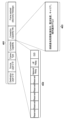
- FIG. 4 is a diagram showing an example of a message format.
- FIG. 5A is a diagram showing an example of the configuration of information elements in a message.
- FIG. 5B is a diagram showing an example of the configuration of information elements in a message.
- FIG. 1 is a diagram illustrating an example of the configuration of a wireless communication system.
- FIG. 2 is a diagram illustrating an example of a hardware configuration of a communication device (UE).
- FIG. 3 is a diagram illustrating an example of a functional configuration of a communication device (UE).
- FIG. 4 is a diagram showing an example of a message format.
- FIG. 5A is a diagram showing an example of the configuration of information elements in a
- FIG. 6 is a diagram illustrating an example of a process flow executed by a UE that transmits a discovery message.
- FIG. 7 illustrates an example of a process flow performed by a UE receiving a discovery message.
- FIG. 8A is a diagram illustrating an example of an operation related to D2D communication.
- FIG. 8B is a diagram illustrating an example of an operation related to D2D communication.
- FIG. 8C is a diagram illustrating an example of an operation related to D2D communication.
- FIG. 9A is a diagram illustrating an example of a process flow related to D2D communication.
- FIG. 9B is a diagram illustrating an example of a process flow related to D2D communication.
- FIG. 9C is a diagram illustrating an example of a process flow related to D2D communication.
- FIG. 9A is a diagram illustrating an example of a process flow related to D2D communication.
- FIG. 9B is a diagram illustrating an example of a process flow related to D
- FIG. 10 is a diagram illustrating an example of an operation related to UE Relay communication.
- FIG. 11 is a diagram showing an example of a process flow related to UE Relay communication.
- FIG. 12 is a diagram for explaining an example of an operation related to network relay communication.
- FIG. 13 is a diagram showing an example of a process flow related to network relay communication.
- FIG. 14 is a diagram showing an example of a message format.
- FIG. 15 is a diagram for explaining services and related information stored in a message.
- FIG. 16 is a diagram showing an example of the flow of a process executed by a UE on the receiving side of a discovery message.
- FIG. 17 is a diagram for explaining a use case of the system.
- FIG. 18 is a diagram illustrating an example of the flow of processing executed in the system.
- FIG. 19 is a diagram illustrating an example of a process flow executed by a UE that transmits a discovery message.
- FIG. 20 is a diagram illustrating an example of a process flow performed by a UE receiving a discovery message.
- FIG. 21 is a diagram showing an example of a message format.
- FIG. 1 shows an example of the configuration of a wireless communication system according to this embodiment.
- This wireless communication system is a system in which wireless communication is performed according to a cellular communication standard such as LTE or NR of the Third Generation Partnership Project (3GPP (registered trademark)), and is configured to include a base station 101 and terminals (UE111 to UE117).
- UE111 to UE117 are configured to be able to perform Sidelink communication defined in those wireless communication standards.
- UE111 to UE117 can communicate in various formats using Sidelink communication.
- UE111 can perform direct wireless communication with UE112 without going through base station 101.
- 3GPP (registered trademark) TS23.304 also includes a provision that allows UE113, which can directly communicate with base station 101, to relay communication between UE114, which cannot directly communicate with base station 101, and the base station.
- 3GPP (registered trademark) technical report TR23.752 reports that a major item of discussion is a configuration in which another UE116 relays communication between UE115 and UE117, which cannot directly communicate with each other.
- Sidelink communication can be used to perform (1) direct communication between UEs, (2) relaying between a UE outside the communication range of a base station and a network, and (3) relaying communication between UEs that exist outside the range in which they can directly communicate with each other.
- (1) may be referred to as D2D communication, Network Relay, or UE Relay.
- the UE detects other UEs that are candidates for connection destinations and selects another UE to connect to from among the candidates.
- UE 114 which exists outside the communication range of base station 101, attempts to connect to base station 101 using Network Relay.
- UE 114 can communicate with base station 101 via UE 113 by connecting to UE 113 connected to base station 101.
- UE 114 discovers, for example, UE 115 that exists nearby as a connection destination candidate for Sidelink communication.
- UE 115 is not connected to base station 101 and cannot provide Network Relay.
- UE 114 could not know whether UE 115 can provide Network Relay until a connection with UE 115 is established. As a result, after connecting with UE115, UE114 recognizes that UE115 cannot provide Network Relay, and disconnects Sidelink. Then, UE114 must perform the process again, starting from the process of detecting other UEs that can provide Network Relay. In this way, since the UE cannot know the status of the other UEs to which it is connected, the process can become complicated. Also, with regard to D2D communication and UE Relay, conventionally, the UE cannot know in advance whether or not other UEs can perform such communication.
- this embodiment provides a method for a UE to determine in advance whether other UEs that are potential connection destinations are capable of performing Sidelink communication in the manner requested by the UE itself.
- a UE transmits a discovery message used to detect other UEs or to enable detection by other UEs, including additional information such as information indicating the type of Sidelink communication requested by the UE itself and the status of communication in the UE itself.
- a UE may transmit a discovery message including information indicating which communication method the UE itself is searching for a Sidelink communication partner in, D2D communication, Network Relay, or UE Relay.
- a UE may transmit a discovery message including information that can specify whether the UE itself can perform D2D communication, whether it can perform Network Relay, and whether it can perform UE Relay, as information indicating the status of communication, etc. Note that such information may be included in a response message for responding to the discovery message.
- a UE that transmits a discovery message may transmit the discovery message including information indicating the requested Sidelink communication method.
- the UE that transmits the response message may include information indicating a communication method that can be performed by the UE in the response message as information indicating the communication status.
- the other UE may transmit the response message only when Sidelink communication is possible in the communication method requested by the UE.
- the other UE can determine which communication method is requested to be used, D2D communication, Network Relay, or UE Relay.
- the UE can identify other UEs that can communicate in the communication method requested by the UE. Only UEs that can perform Sidelink communication in the mode requested by the source UE, as indicated in the discovery message, may transmit a response message to the discovery message.
- FIG. 2 shows an example of a hardware configuration of a communication device that operates as a UE according to this embodiment.
- the configuration shown in FIG. 2 is merely an example, and the UE may be realized by a hardware configuration different from that shown in FIG. 2.
- the UE may not have a part of the hardware configuration shown in FIG. 2, or may include additional configuration.
- the UE has, for example, a storage unit 201, a control unit 202, a function unit 203, an input unit 204, an output unit 205, a communication unit 206, and an antenna 207.
- the storage unit 201 is configured to include memories such as Read Only Memory (ROM) and Random Access Memory (RAM), and stores various information such as programs for performing various operations described below and communication parameters for wireless communication.
- memories such as ROM and RAM
- the storage unit 201 may also include storage media such as flexible disks, hard disks, optical disks, magneto-optical disks, CD-ROMs, CD-Rs, magnetic tapes, non-volatile memory cards, and DVDs.
- the storage unit 201 may also include multiple memories.
- the control unit 202 is composed of, for example, a processor such as a CPU or MPU, an application specific integrated circuit (ASIC), a digital signal processor (DSP), a field programmable gate array (FPGA), etc.
- CPU is an acronym for Central Processing Unit
- DSP digital signal processor
- FPGA field programmable gate array
- the control unit 202 controls the entire UE, for example, by executing a program stored in the memory unit 201.
- the control unit 202 may control the UE in cooperation with the program stored in the memory unit 201 and an OS (Operating System).
- the control unit 202 may also include multiple processors, such as a multi-core processor.
- the control unit 202 can also control the functional unit 203 to embody a predetermined function such as an impact detection function, an imaging function, a printing function, or a projection function.
- the functional unit 203 is configured to include hardware for the UE to execute a predetermined process.
- the functional unit 203 has an imaging function, it has an optical lens unit, an optical system that controls the aperture, zoom, focus, and the like, and an imaging element for converting the light (image) introduced through the optical lens unit into an electrical image signal.
- the imaging element generally uses a CMOS (Complementary Metal Oxide Semiconductor) or a CCD (Charge Coupled Device).
- the functional unit 203 Under the control of the control unit 202, the functional unit 203 converts the subject light imaged by the lens included in the functional unit 203 into an electrical signal using the imaging element, performs noise reduction processing, and outputs the digital data as image data.
- the image data is recorded in the storage unit 201 in accordance with the DCF (Design Rule for Camera File system) standard.
- the functional unit 203 has an impact detection function, it includes a sensor, and when the sensor detects an impact or vibration of a certain level or more, it notifies the control unit 202 of the detection result.
- the UE may be a smartphone, digital still camera, network camera, printer, in-vehicle device, etc. with an imaging function.
- the UE is not limited to these, and may be, for example, a projector that projects an image on a projection unit, or a head-mounted display that provides a user with an image based on data received from the outside.
- the UE may be a wearable device such as wearable glasses or a smart watch that has a function of projecting an image on a projection surface such as the user's retina or glass.
- the in-vehicle device means a control device that is standardly installed in a vehicle such as an automobile, a car navigation device installed in a vehicle such as an automobile, a drive recorder device installed in a vehicle such as an automobile for recording images during driving, etc.
- the input unit 204 receives various operations from the user.
- the output unit 205 performs various outputs to the user.
- the output by the output unit 205 includes at least one of display on a screen, audio output by a speaker, vibration output, and the like.
- both the input unit 204 and the output unit 205 may be realized by a single module, such as a touch panel.
- the communication unit 206 is configured to include hardware (e.g., a radio frequency (RF) chip, a baseband chip, etc.) for performing wireless communication conforming to the 3GPP (registered trademark) cellular communication standard.
- the communication unit 206 controls the corresponding antenna 207 to transmit and receive radio signals for wireless communication. Note that while FIG. 2 shows a configuration with one antenna 207, multiple antennas may be used.
- the communication unit 206 is configured to be able to perform Sidelink communication with other UEs, in addition to communication with a base station, for example.
- the UE includes a function control unit 301, a storage control unit 302, a discovery message generation unit 303, a discovery message analysis unit 304, and a communication control unit 305.
- the function control unit 301 controls the operation of each function of the UE, for example, by causing the control unit 202 to execute a program stored in the storage unit 201.
- the storage control unit 302 executes various controls related to the storage of information, such as, for example, storing information in the storage unit 201 and retrieving information from the storage unit 201.
- the discovery message generation unit 303 generates a discovery message to be sent to detect other UEs. Furthermore, the discovery message generation unit 303 may generate a response message to a discovery message received from another UE.
- the discovery message analysis unit 304 analyzes the discovery message sent from the other UE.
- the communication control unit 305 controls the communication unit 206 to execute communication with the base station and Sidelink communication with the other UE.
- the communication control unit 305 is configured to send out the discovery message generated by the discovery message generation unit 303, or to supply the discovery message analysis unit 304 with a discovery message sent and received from another UE.
- FIG. 4 shows exemplary formats of a discovery message and a response message.
- a discovery message will be described, but unless otherwise specified, the response message may also include similar contents.
- the discovery message is a message transmitted when a UE performs a process of detecting other UEs
- the response message is a message for other UEs that receive the discovery message to detect the presence of the device.
- the discovery message and the response message used in the 5G ProSe Direct Discovery procedure are in the formats shown in FIG. 4, FIG. 5A, and FIG. 5B.
- Each message is used to discover other nearby UEs that support 5G Prose by direct wireless transmission between two UEs using 5G NR (New Radio) technology.
- 5G NR New Radio
- ProSe is an abbreviation for Proximity Service.
- the Destination Layer-2 ID stores a Layer-2 ID indicating the destination of the message.
- the Destination Layer-2 ID of a discovery message does not store information indicating an individual other UE as the destination, but may store information indicating a broadcast, for example.
- the Destination Layer-2 ID of a response message may store the ID of the UE that sent the discovery message.
- the Source Layer-2 ID stores a Layer-2 ID indicating the source of the message.
- the Frame type stores information indicating the type of this message. For example, information indicating whether it is a discovery message or a response message is stored in the Frame type.
- the Frame type of a discovery message is set to "Prose Direct Discovery".
- information indicating the mode of Sidelink communication requested by the UE that transmitted the discovery message 401 (the UE that performs the detection process for other UEs) is set.
- bits for setting the Sidelink communication methods “Network Relay”, “UE Relay”, and “D2D” can be prepared as information indicating the mode of Sidelink communication.
- a bit corresponding to the communication method requested by the UE that transmitted the discovery message is set to "1"
- a bit corresponding to the communication method that is not requested is set to "0".
- bits corresponding to modes other than these communication methods may be prepared, and a bit corresponding to a mode that is requested may be set to "0", and a bit corresponding to a mode that is not requested may be set to "1". If a UE wants to obtain all information about other UEs in its vicinity, it does not need to set anything in Connection Capability (for example, all bits are set to "0").
- the UE When another UE receives a discovery message with nothing set in Connection Capability 402, it may return a response message in which a Sidelink communication method that the UE can execute is set.
- a discovery message When another UE receives a discovery message, it transmits a response message in which the ID of the UE that sent the message is specified as the Destination Layer-2 ID.
- the Sidelink communication method that the UE that sends the response message can execute may be set in Connection Capability 402 of the response message. For example, a bit corresponding to a Sidelink communication method that the UE can execute may be set to "1", and a bit corresponding to a Sidelink communication method that the UE cannot execute may be set to "0".
- a Sidelink communication method that can be executed may be indicated by "0", and a Sidelink communication method that cannot be executed may be indicated by "1". If the UE is capable of executing multiple communication methods, it may set the bits corresponding to each of the multiple communication methods to values indicating that the communication methods are executable. On the other hand, when the UE receives a discovery message in which a requested communication method is specified, it may return a similar response message if it is capable of executing Sidelink communication of that communication method. In this case, nothing may be set in the Connection Capability 402 of the response message.
- the UE that sent the discovery message may presume that it is capable of executing Sidelink communication in the requested communication method in response to receiving a response message in which the ID of the UE itself is specified in the Destination Layer-2 ID.
- the UE may not return a response message if it is not capable of executing Sidelink communication of the requested communication method specified in the discovery message.
- connection Capability Info 403 necessary information is set according to the Sidelink communication method that can be executed.
- the identifier of the base station to which the UE that transmits this message is connected information indicating the carrier, base station information such as the received radio wave strength of the signal from the base station, and the terminal identifier of the UE are stored in the Connection Capability Info 403.
- the identifier of the base station may be, for example, a physical cell identifier.
- the information indicating the carrier may be information capable of identifying a network such as a Public Land Mobile Network (PLMN) identifier.
- PLMN Public Land Mobile Network
- the information indicating the carrier may be information capable of identifying a frequency band used such as an Absolute Radio Frequency Channel Number (ARFCN).
- ARFCN Absolute Radio Frequency Channel Number
- the carrier information may also be information on the communication carrier that operates the base station.
- the base station information may be configured to include at least one of the above-mentioned identifiers, carrier (frequency band/communications operator) information, and received radio wave strength, and may additionally or alternatively include other information.
- the terminal identifier may be, for example, an identifier such as Temporary Mobile Subscriber Identities (TMSI) related to communication with the base station.
- TMSI Temporary Mobile Subscriber Identities
- the terminal identifier may also be any other identifier capable of identifying the UE.
- FIG. 5A shows an example of information items set in Connection Capability Info 403.
- an operation state identifier, a base station identifier, a connected terminal identifier, a base station signal strength, connected base station information, etc. are set in Connection Capability Info 403.
- Each of these pieces of information is assigned an index of 1 to 5, and the index is used to declare which information is to be transmitted in Connection Capability Info 403.
- the operation state identifier follows in the subsequent item 502.
- "01" indicating that the function for executing Network Relay is being activated is set as item 502.
- the base station identifier may be, for example, a fixed length, or may be a variable length.
- the length of the information is indicated, for example, as indicated by "06" in item 504, and the base station identifier "XXXXX" is set in item 505.
- "05" indicating the connection base station information is set in item 506, and the length of the information is indicated as "04" in item 507.
- connection base station information is configured so that further information can be represented by the extended index.
- “01” is set in item 508, and “01” is set in the following item 509, indicating that the UE that sent this message is connected to a base station of company A.
- "02” is set in item 510, and "51” is set in the following item 511, indicating that the frequency band being used is n78.
- these pieces of information are merely examples, and information in other formats may be set as Connection Capability Info 403.
- the Frame Payload stores the main body of information exchanged between devices using messages.
- the UE generates a discovery message as described above and sends it to the surroundings (S601).
- the UE acquires all information of the surrounding UEs, the UE sends it without setting anything in the Connection Capability.
- the UE detects only other UEs capable of performing D2D communication (supporting the D2D communication function), for example, the UE sets the bit corresponding to D2D communication in the Connection Capability to a predetermined value.
- the UE detects other UEs capable of performing UE Relay or Network Relay the UE sets the corresponding bit in the Connection Capability to a predetermined value.
- the UE may set the corresponding bit of the second communication method that it requests to use, among one or more first communication methods supported by the own device, to a predetermined value. That is, the UE may not set the corresponding bit to a predetermined value for a communication method that the UE does not support.
- the UE waits to receive a response message from another UE (S602).
- the UE receives a response message from another UE, it checks the value of Connection Capability in the message (S603).
- the Connection Capability in the response message stores information indicating whether the other UE that transmitted the response message can perform D2D communication, UE Relay, or Network Relay. Therefore, the UE can identify which communication method the other UE that transmitted the response message can perform Sidelink communication by analyzing the Connection Capability.
- the UE checks whether there is another UE in the vicinity that can perform D2D communication (S604). If there is no other UE in the vicinity that can perform D2D communication, the UE may end the process as it is. If there is a surrounding UE in the vicinity that can perform D2D communication, the UE determines whether to perform D2D communication with the surrounding UE. For example, when the UE and the surrounding UE are both connected to the same base station, there are cases where communication via the base station can perform faster communication without performing D2D communication.
- the frequency band used to connect to the base station is a frequency band such as a millimeter wave that can secure a sufficiently wide signal bandwidth and can use a large amount of resources. For this reason, in this embodiment, when the UE is connected to the same base station as the other UE, it is determined not to perform D2D communication.
- the UE If the UE is not within the communication range of any base station (YES in S605), the UE is not connected to the same base station as the surrounding UEs, and therefore performs D2D communication (S607). Also, if the UE is connected to any base station (or is in the cell provided by that base station), the UE checks the Connection Capability Info of the response message. Then, the UE obtains the base station identifier to which the other UE that sent the response message is connected (or is in the cell), and determines whether the other UE is within the communication range of the same base station as the UE (S606).
- the UE may determine to perform D2D communication even if another UE is connected to (or in) the same base station when, for example, the frequency band used in the connected (or in) base station is not a predetermined frequency band such as a millimeter wave band.
- the UE may determine to perform D2D communication when, for example, the radio quality between the connected (or in) base station of the UE and the other UE is below a predetermined value.
- the UE may determine not to perform D2D communication. In this way, whether or not to perform D2D communication can be determined based on various criteria, and is not limited to the above-mentioned determination based on whether or not the UE is connected to the same base station.
- a process will be described in the case where a UE desires that another UE relays communication between the UE and the communication partner UE through UE Relay communication.
- the UE confirms that there are other UEs in the vicinity that can perform UE Relay communication by checking the Connection Capability of the received response frame (S608).
- a UE that has established a connection with another UE through Sidelink communication or a UE that belongs to a group that includes other UEs for performing Sidelink communication transmits a response frame indicating that it can perform UE Relay communication. If there are no such other UEs, the UE ends the process as it is.
- the UE analyzes the Connection Capability Info in the response frame transmitted from the other UE. The UE then determines whether there are other UEs that can perform Sidelink communication with the UE that is the communication partner of the UE (S609) among the other UEs that sent the response frame. If there are other UEs in the vicinity that can perform Sidelink communication with the communication partner UE (YES in S609), the UE establishes a connection with the other UE and performs UE Relay communication using Sidelink communication (S610). On the other hand, if there are no other UEs in the vicinity that can perform Sidelink communication with the communication partner UE (NO in S609), the UE ends the process as it is (S610).
- the UE confirms that there is another UE in the vicinity that can perform Network Relay communication by checking the Connection Capability of the received response frame (S611). Then, the UE analyzes the Connection Capability Info in the response frame sent from such another UE.
- the Connection Capability Info stores information such as the identifier of the base station to which the UE is to connect, the reception strength of the radio waves from that base station, the carrier that operates that base station, and the frequency band used for communication. Based on this information, the UE determines which of the other UEs that can perform Network Relay to connect to.
- the UE places importance on good wireless quality between the base station and selects another UE with good reception signal strength with the base station as the connection destination (S612).
- the UE may allow connection only to other UEs connected to a specific carrier (e.g., a carrier with which the device has a contract).
- the UE may also determine that it will preferentially connect to other UEs connected to a base station that uses a high-frequency band that allows wideband transmission and has a reception signal strength equal to or greater than a predetermined value.
- the UE may also select another UE to connect to according to a priority order obtained by inputting the information stored in the Connection Capability Info into a predetermined function.
- the UE connects to the selected other UE and executes Network Relay communication (S613).
- the other UE may be in a state of being connected to the base station or in a state of waiting. If another UE is in standby, it may establish a connection with the base station in standby state in response to the UE receiving a connection request for network relay communication.
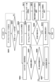
- FIG. 7 An example of the flow of processing executed by a UE that receives a discovery message and returns a response message will be described with reference to FIG. 7. Note that this processing is executed, for example, by using the discovery message analysis unit 304. Also, the processing in FIG. 7 is merely an example, and for example, some processing steps may be omitted, or processing steps not shown may be added.
- a UE When a UE receives a discovery message sent from another surrounding UE (S701), it analyzes the Connection Capability contained therein and checks the Sidelink communication method requested by the other UE (S702).
- the UE includes information indicating whether the UE itself can perform (supports) D2D communication in the Connection Capability of the response message (S704). For example, if the UE itself supports D2D communication, the UE sets the bit corresponding to D2D communication in the Connection Capability to "1". Similarly, if another UE has requested UE Relay communication (S706), the UE includes information indicating whether the UE itself supports UE Relay communication in the Connection Capability of the response message (S707). Also, if another UE has requested Network Relay communication (S709), the UE includes information indicating whether the UE supports Network Relay communication in the Connection Capability of the response message (S710). Furthermore, if the UE receives a discovery message from another UE that does not specify a specific Sidelink communication method (S712), the UE includes the functions that the UE supports in the Connection Capability (S713).
- the UE also includes associated information related to the communication method that is indicated in the Connection Capability as being supported in the Connection Capability Info (S705, S708, S711, S714). For example, when the UE includes information indicating that it supports D2D communication in the response message, it sets the base station identifier of the base station in which the UE is located or connected in the Connection Capability Info (S705). When the UE includes information indicating that it supports UE Relay communication in the response message, it sets the terminal identifier capable of identifying other connected UEs in the Connection Capability Info (S708).
- the UE when the UE includes information indicating that it supports Network Relay communication in the response message, the UE sets base station information related to the connected or currently located base station in Connection Capability Info (S711).
- the base station information includes, for example, information such as a base station identifier, received signal strength, carrier information, and band.
- the UE when the UE receives a discovery message that does not specify a specific Sidelink communication method, the UE sets all associated information related to functions supported by the device in Connection Capability Info (S714). Note that the UE can generate and transmit one response message including information on multiple communication methods, but may also generate and transmit individual response messages for each communication method.
- FIG. 8A to FIG. 8C show some situations in which D2D communication is required, and FIG. 9A to FIG. 9C show examples of processing flows in each situation.
- D2D communication can be used, for example, for vehicles including UEs having a Sidelink communication function to exchange information between the vehicles and run in a convoy.
- D2D communication can also be used when such vehicles directly communicate with road-mounted devices (such as traffic lights) including UEs having a Sidelink communication function to exchange information about road information.
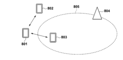
- UE801 is assumed to be performing D2D communication.
- UE802 and UE803 exist around UE801.
- UE803 is assumed to be staying within the range of cell 805 formed by base station 804 and can communicate with base station 804.
- UE801 transmits a discovery message to the surroundings without specifying a specific communication method in Connection Capability, and UE802 and UE803 receive the message (F901).
- UE802 transmits a response message to UE801 in which a value indicating that D2D communication is possible and that it is not within the range of any base station is set (F902).
- UE803 sets that Network Relay communication is possible and base station information regarding base station 804, and transmits the response message to UE801 (F903).
- UE801 desires D2D communication, it determines whether or not to perform D2D communication with UE802 as a communication partner.
- UE801 since UE801 is not present within the communication range of any base station (YES in S605), it determines to perform D2D communication with UE802 and executes connection processing (F904).
- UE802 and UE803 may include in the associated information whether or not the communication function they support is activated. This allows UE801 to identify whether or not communication can be immediately started using the communication function supported by each UE.
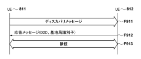
- UE811 is assumed to be attempting to perform D2D communication.
- UE812 exists around UE811.
- UE811 is assumed to be staying within the range of cell 815 formed by base station 813 and can communicate with base station 813.
- UE812 is assumed to be staying within the range of cell 816 formed by base station 814 and can communicate with base station 814.
- UE811 transmits a discovery message to the surroundings without specifying a specific communication method in Connection Capability, and UE812 receives the message (F911).
- UE812 transmits a response message to UE811 with a value set indicating that D2D communication is possible and that it is within the range of base station 814 (F912).
- UE811 recognizes that D2D communication with UE812 is possible, and determines whether or not to perform D2D communication with UE812 as a communication partner.
- UE811 determines to perform D2D communication with UE812 because the UE811 itself is within the communication range of base station 813 and UE812 is within the communication range of base station 815 different from base station 813 (NO in S606).
- UE811 performs a connection process with UE812 (F913).
- UE812 may include in the associated information whether or not the supported D2D communication function is activated. This allows UE811 to identify whether or not it is possible to immediately start D2D communication.
- UE821 is assumed to be attempting to perform D2D communication.
- UE822 exists around UE821.
- both UE821 and UE822 are assumed to be staying within the range of cell 824 formed by base station 823 and can communicate with base station 823.
- UE821 transmits a discovery message to the surroundings without specifying a specific communication method in Connection Capability, and UE822 receives the message (F921).
- UE822 transmits a response message to UE821 with a value indicating that D2D communication is possible and that it is within the range of base station 823 (F922).
- UE821 recognizes that it is possible to perform D2D communication with UE822, and determines whether or not to perform D2D communication with UE822 as a communication partner.
- UE821 determines not to perform D2D communication with UE822 because the UE821 itself is within the communication range of base station 823 and UE822 is also within the communication range of the same base station 823 (YES in S606). Then, UE821 does not perform connection processing with UE822 (F923) and performs communication, for example, via base station 823.
- the UE can easily identify other UEs capable of performing D2D communication and perform D2D communication with the other UEs. Furthermore, the UE can appropriately determine whether or not to perform D2D communication, for example, not to perform D2D communication with other UEs connected to the same base station, based on the associated information included in the response message.
- FIG. 10 shows a situation in which UE Relay communication is requested
- FIG. 11 shows an example of the processing flow in this situation.
- UE Relay can be used, for example, when a vehicle including a UE with Sidelink communication function outside the communication range of a base station uses UE Relay to exchange road information between vehicles.
- a roadside device (such as a traffic light device) including a UE with Sidelink communication function can support communication between vehicles including a UE with Sidelink communication function outside the communication range of a base station by supporting UE Relay.
- UE1001 is attempting to communicate with UE1003.
- UE1002 and UE1004 are present around UE1001, and UE1003 and UE1005 are present in an area to which UE1001 cannot directly connect.
- UE1002 can communicate directly with UE1003, and UE1004 can communicate directly with UE1005.
- UE1002 and UE1004 support UE Relay communication.
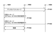
- UE1001 transmits a discovery message with UE Relay set in Connection Capability to search for other UEs that can relay communication with UE1003 using the UE Relay communication function (F1101).
- UE1002 and UE1004 transmit a response message indicating that they support the UE Relay communication function to UE1001 (F1102, F1103).
- UE1002 may include the terminal identifier of UE1003 as associated information in the Connection Capability Info in the response message.
- UE1004 may include the terminal identifier of UE1005 as associated information in the Connection Capability Info in the response message.
- UE1001 When UE1001 receives these response messages, it can determine that UE1002 can communicate with UE1003 through UE Relay communication, and that UE1004 can communicate with UE1005 through UE Relay communication. Then, since UE1001 desires to communicate with UE1003, it selects UE1002, which can communicate with UE1003 through UE Relay communication, as the connection destination and executes the connection establishment process (F1104). Note that UE1002 and UE1004 may include in the associated information whether or not the supported UE Relay communication function is activated. This allows UE1001 to determine whether or not it can immediately start communication with the desired other device through the UE Relay communication function.
- the UE can easily identify other UEs capable of performing UE Relay communication, and can receive UE Relay communication provided by the other UEs. Furthermore, the UE can appropriately select other UEs that can communicate with an appropriate partner device based on the associated information in the response message. This allows the UE to appropriately select other devices that support the UE Relay communication function, and communicate with the desired partner device.
- FIG. 12 shows a situation in which Network Relay communication is requested
- Figure 13 shows an example of the processing flow in this situation.
- the Network Relay function can be used, for example, to extend the communication range of a base station.
- a vehicle that includes a UE with a Sidelink communication function and is outside the communication range of a base station can connect to the base station by relaying communication from a roadside device that includes a UE with a Sidelink communication function and supports the Network Relay function. This allows a vehicle that is outside the communication range of a base station to access the Internet, etc., and obtain road information, etc.
- UE1201 searches for other UEs that support the Network Relay function in order to connect to a base station.
- UE1202, UE1203, and UE1204 are assumed to be present around UE1201.
- UE1202 and UE1203 are assumed to be present within communication range 1206 of base station 1205 and to support Network Relay.
- UE1204 is assumed to be present outside communication range 1206 and not to support Network Relay.
- the radio wave strength from base station 1205 at UE1202 is assumed to be higher than the radio wave strength from base station 1205 at UE1203.
- UE1201 transmits a discovery message with Network Relay set in Connection Capability to search for other UEs that support the Network Relay communication function (F1301).
- UE1202 and UE1203 support the Network Relay function, and therefore return a response message including information indicating that they support the Network Relay function to UE1201 (F1302, F1303).
- UE1202 and UE1203 transmit a response message including associated information such as the base station identifier of the connected or present base station 1205, received signal strength, carrier information, and frequency band used.
- UE1202 and UE1203 may include in the associated information whether the supported Network Relay function is activated. This allows UE1201 to determine whether it can immediately start communication with the base station using the Network Relay function. On the other hand, UE1204 does not support the Network Relay function, so it does not return a response message.
- UE1201 When UE1201 receives the response messages from UE1202 and UE1203, it can determine that each of them supports the Network Relay function. Then, from those response messages, UE1201 determines the base station information to which UE1202 and UE1203 are connected, and selects, for example, UE1202, which has good received signal strength, as the connection destination, and executes connection processing with UE1202 (F1304).
- the UE can easily identify other UEs capable of performing Network Relay communication, and can receive Network Relay communication provided by the other UEs. Furthermore, the UE can appropriately select other UEs that can communicate with the base station with better wireless quality, for example, based on the associated information in the response message. This allows the UE to appropriately select other devices that support the Network Relay communication function and communicate with the base station.
- a method has been described in which a UE that receives a discovery message returns a response message setting the communication method that it supports.
- the UE may periodically send a signal such as a notification signal setting the communication method that it supports even if it has not received a discovery message.
- a UE can easily identify other UEs that can perform Sidelink communication using the communication method requested by the UE itself by detecting the signals sent by other UEs in the vicinity.
- a discovery message in the format shown in FIG. 14 is used.
- the Destination Layer-2 ID, Source Layer-2 ID, and Frame type are the same as those described in FIG. 4. That is, in this embodiment, it is assumed that the discovery message used in the 5G ProSe Direct Discovery procedure has the format shown in FIG. 14.
- the discovery message used in this embodiment includes a "Service" field after the Frame type.
- the Service field stores information indicating the service that the UE that transmitted the discovery message wants other UEs to execute.
- the Frame Payload stores information according to the Service.
- the UE may generate and transmit a discovery message in which, for example, "Recording" is stored in Service and the location information acquired by the UE is stored in Frame Payload.
- the UE that has received the discovery message may generate and return a response frame using a format such as that shown in FIG. 14 as necessary.
- the UE that has received the discovery message returns a response frame in which information indicating a service that the UE can execute (a service requested by the UE that sent the discovery message) is stored in Service.
- the UE may store information corresponding to the service in Frame Payload of the response frame. That is, in this embodiment, information indicating a service that the UE can execute is stored in the response frame of the discovery message used in the 5G ProSe Direct Discovery procedure.
- FIG. 15 shows an example of information to be set in a discovery message.
- recording, rescue, platooning group formation, and junction approach detection are shown as examples of values indicating services that can be set in the Service field.
- the following describes information set by the first UE on the transmission side of the discovery message when each of these services is stored in the Service field. Furthermore, the conditions under which the second UE on the receiving side responds to the message, the process to be executed together with the response, and the information to be set in the response message are also described. Note that the contents of the service are not limited to the above four, and values indicating services other than these may be set in the Service field.
- the above four services are services for the case where the UE is mounted on the vehicle
- services for the case where the UE is not mounted on the vehicle may be specified.
- the information stored in the discovery message, the conditions for responding in the receiving UE, the process to be executed, and the information to be included in the response message are not limited to the example of FIG. 15. That is, for example, even if the service is "recording", it is different from the one shown in FIG. 15 and described later.
- the first UE that transmits the discovery message stores the location information of its own device (first UE) in the discovery message.
- the second UE that receives this message returns a response message to the first UE when, for example, all of the following four conditions are satisfied.
- the first condition is that the device (second UE) is performing shooting using the shooting function it has at the time of receiving the discovery message. This is based on the condition that when a phenomenon such as a traffic accident occurs, there is a possibility that the phenomenon is being shot. That is, when a discovery message is transmitted after the occurrence of such a phenomenon, if the second UE is not performing shooting at that time, it is estimated that the video desired to be recorded has not been shot in the second UE. For this reason, if the second UE is not performing shooting at the time of receiving the discovery message, the second UE does not transmit a response message to the first UE.
- the second condition is that the second UE is present in an area within a certain distance from the first UE.
- the communication distance of Sidelink communication between UEs is, for example, about 500 meters. Therefore, the certain range can be set to be equal to or less than this communication distance.
- an image taken by a second UE that is present at a close distance from the site is more useful for identifying the situation. Therefore, if the second UE is far away from the first UE and it is estimated that useful shooting is not possible, the second UE does not transmit a response message to the first UE.
- the above-mentioned certain range can be set so that such a useful image can be obtained.
- the third condition is that the attitude of the own device (second UE) is such that the position of the UE (first UE) that transmitted the discovery message can be photographed by the photographing function of the own device. That is, when the second UE is in a position that makes it impossible to take a picture of a recording target such as an accident scene, the second UE does not transmit a response message to the first UE even if the distance between the second UE and the first UE is sufficiently close.
- the fourth condition is that the second UE permits the provision of the recorded image to others.
- the recorded image is the property of the photographer, such as an image taken by a drive recorder, the image should not be given to others without the owner's permission. For this reason, when the second UE does not permit the provision of the stored image to others, the second UE does not transmit a response message to the first UE.
- the second UE that satisfies the above-mentioned first to fourth conditions may transmit a response message to the first UE.
- the second UE decides to send a response message, it saves the video captured by its own device's image capture function (and does not discard the video for at least a certain period of time).
- the second UE also includes identification information used for Sidelink communication, such as the International Mobile Equipment Identity (IMEI), in the response message and sends it to the first UE. This allows the first UE to subsequently request the communication device that recorded the video to send the video, addressed to the IMEI.
- IMEI International Mobile Equipment Identity
- the first UE stores its own location information and the rescue target requested by its own device in a discovery message and transmits it.
- information indicating what kind of rescue is needed such as “breakdown,” “out of gasoline,” “distress,” and “approach of a tailgating vehicle”
- the discovery message is stored in the discovery message as information on the rescue target.
- information indicating a more detailed rescue target such as "engine failure” or “flat tire,” may be indicated as information on "breakdown.”
- the second UE transmits a response message to the discovery message on the condition that its own device can head for rescue or that communication via the core network is possible at the time of receiving the discovery message.
- the second UE when the second UE transmits a response message because its own device can head for rescue, it heads for the location of the first UE without performing any particular processing within the device. In addition, in this case, the second UE may transmit information on the scheduled time when its own device will arrive at the location of the first UE in the response message. On the other hand, when the second UE transmits a response message because communication via the core network is possible, the second UE performs relay communication to another rescuer via the core network. In this case, the second UE may not transmit a response message generated by itself, but may forward a response message generated by the other rescuer to the first UE. This response message may include information about the scheduled time when the other rescuer will arrive at the location of the first UE.
- the second UE may decide whether to send a response message by manual operation by the user.
- the second UE transmits the response message to the first UE, including a password for joining the group and an identifier of the device itself.
- the second UE may use, for example, the nickname of the device itself as the identifier.
- the first UE may obtain the password and identifier related to the second UE and determine whether to allow the second UE to join the group.
- a plurality of vehicles including UEs that belong to the group formed in this way may be controlled to perform automatic platooning using, for example, known automatic driving technology.
- the discovery message includes the location information of the first UE and information indicating the traveling direction.
- the second UE transmits a response message when the distance to the first UE is within a certain range and the second UE is traveling in a direction approaching the meeting point. In one example, the second UE does not perform any particular process other than transmitting the response message.
- the second UE transmits a response message to the first UE including the location information of its own device (the second UE) and information indicating the traveling direction. This allows the first UE to detect that it is approaching the second UE at the meeting point ahead of its own device.
- FIG. 16 shows an example of the flow of processing executed by the second UE that receives the discovery message in this embodiment.
- the second UE receives a discovery message sent from another UE (S1601), it checks the services included in the discovery message (S1602). If “record” is set in the Service field of the discovery message (S1603), the second UE executes processing related to "record” (S1604). On the other hand, if “rescue” is set in the Service field of the discovery message (S1605), the second UE executes processing related to "rescue” (S1606). Also, if "platooning group formation” is set in the Service field of the discovery message (S1607), the second UE executes processing related to "platooning group formation” (S1608).
- the second UE executes processing related to "Meeting point approach detection” (S1610). Note that the processing related to each service is as described above, and will not be repeated here.
- vehicle 1701, vehicle 1702, network camera 1703, vehicle 1704, vehicle 1705, and Road Side Unit (RSU 1706) are assumed to be present within a certain range.
- vehicle 1701 and vehicle 1702 collide and a UE mounted on vehicle 1701 requests other UEs in the vicinity to provide captured images.
- the UE mounted on vehicle 1701 transmits a discovery message.
- this UE will be referred to simply as "vehicle 1701”.
- vehicle 1702, network camera 1703, vehicle 1704, vehicle 1705, and RSU 1706 will be used to refer to the UEs in those devices.
- Vehicle 1701 sets "record” in the Service field in the discovery message, and sets the location information of vehicle 1701 in Frame Payload as information according to the service.
- Vehicle 1702 also performs the above-mentioned processing, but since the processing performed by vehicle 1701 is similar, only vehicle 1701 will be described here, and the description of vehicle 1702 will be omitted.
- vehicle 1702 has a photographing function and can only photograph in the direction of travel, but does not permit the provision of recorded images.
- the arrow indicates the photographing direction.
- Network camera 1703 has a photographing function and can record in all directions (at least the entire area within the lane in which vehicle 1701 etc. is traveling), and permits the provision of recorded images.
- Vehicle 1704 has a photographing function and can photograph in the direction of travel and the opposite direction, and also permits the provision of recorded images.
- Vehicle 1705 has a photographing function and can only photograph in the direction of travel, and permits the provision of recorded images.
- RSU 1706 does not have a photographing function.
- Vehicle 1701 is assumed to be capable of performing Sidelink communication with, for example, vehicle 1702, network camera 1703, vehicle 1704, vehicle 1705, and RSU 1706. That is, the communication range of vehicle 1701 includes the position of RSU 1706. On the other hand, vehicle 1701 may use a range different from the communication range as a range for searching for other UEs using discovery messages, such as the hatched area in FIG. 17.
- FIG. 17 shows a situation in which vehicle 1701 uses a search range that includes the positions of vehicle 1702, network camera 1703, vehicle 1704, and vehicle 1705, but does not include the position of RSU 1706.
- FIG. 18 shows an example of the operation executed by the system in the situation shown in FIG. 17. Note that this shows an example of the operation when vehicle 1701 transmits a discovery message requesting the "recording" service to other UEs in the vicinity upon collision with vehicle 1702.
- vehicle 1701 when vehicle 1701 detects an impact of a certain magnitude or greater (F1801), it sets the Service field to "record,” generates a discovery message in which its own device's location information is stored in the Frame Payload, and sends it to the surroundings (F1802).
- the location information of vehicle 1701 can be acquired, for example, using a GPS function installed in vehicle 1701.
- Vehicle 1702, network camera 1703, vehicle 1704, vehicle 1705, and RSU 1706 receive the discovery message and identify that the Service field is set to "record.” Then, vehicle 1702, network camera 1703, vehicle 1704, vehicle 1705, and RSU 1706 decide whether to send a response message to the discovery message.
- Vehicle 1702 is capturing images using its own device, but has not permitted the provision of such images. Therefore, vehicle 1702 decides not to send a response message (F1803) and ends the process.
- the network camera 1703 is taking pictures in the direction of the vehicle 1701, the distance from the vehicle 1701 is within a certain range, and the provision of images is permitted, so it decides to return a response message (F1804).
- the network camera 1703 saves the captured image (F1805) and returns a response message including the IMEI of its own device to the vehicle 1701 (F1806).
- the vehicle 1701 then saves the IMEI of the network camera 1703 in order to obtain images from the network camera 1703 later (F1807).
- the vehicle 1704 also decides to return a response message (F1808), saves the captured image (F1809), and returns a response message including the IMEI of its own device to the vehicle 1701 (F1810).
- the vehicle 1701 then saves the IMEI of the vehicle 1704 (F1811).
- Vehicle 1705 is taking pictures using its own device, has permission to provide video images, and is within a certain distance from vehicle 1701, but is not taking pictures in the direction of vehicle 1701. Therefore, vehicle 1705 decides not to send a response message (F1812) and ends the process.
- the RSU 1706 does not have a photographing function, and the distance from the vehicle 1701 is not within a certain range. For this reason, the RSU 1706 decides not to send a response message (F1813) and ends the process.
- vehicle 1701 requests network camera 1703 to send the video it has stored, with the IMEI of network camera 1703 stored in F1807 as the destination (F1814).
- network camera 1703 receives the request message from vehicle 1701, it transmits the video it has stored in F1805 to vehicle 1701 (F1815).
- vehicle 1701 receives the video from network camera 1703, it stores the video (F1816).
- Vehicle 1701 also requests vehicle 1704 to send the video it has stored, with the IMEI of vehicle 1704 stored in F1811 as the destination (F1817).
- vehicle 1704 receives the request message from vehicle 1701, it transmits the video it has stored in F1809 to vehicle 1701 (F1818).
- vehicle 1701 receives the video from vehicle 1704, it stores the video (F1819).
- a UE requesting the "recording" service such as a UE installed in vehicle 1701
- the UE requesting the "recording" service may be referred to as a first UE
- the UE that is requested to provide the "recording" service may be referred to as a second UE.
- the first UE monitors whether an impact (collision) of a certain level or more has occurred (S1901). Note that this monitoring is for determining the trigger for transmitting a discovery message requesting a service, and when another trigger is used, state monitoring corresponding to that trigger may be performed. For example, when a discovery message is transmitted in response to the reception of a specific user operation, the first UE may monitor whether the specific user operation has been received. For example, when there is another vehicle driving dangerously around the vehicle 1701, a discovery message may be transmitted when a user operation is performed to request recording from the surrounding vehicles.
- the first UE When the first UE detects a trigger for transmitting a discovery message (here, a collision) (YES in S1901), it generates a discovery message in which a requested service (here, "recording") is set, and broadcasts it (S1902). Then, the first UE waits to receive a response message from other surrounding UEs (S1903).
- the first UE may transmit the discovery message multiple times at regular intervals, or may retransmit the discovery message if it does not receive a response message for a certain period of time. The first UE may also terminate the process if it does not receive a response message for a certain period of time.
- the first UE When the first UE receives the response message (YES in S1903), it acquires and stores the IMEI of the second UE that is the sender of the response message, which is included in the response message (S1904). The first UE then requests the second UE to provide the stored video, addressed to the stored IMEI (S1905), and acquires the video from the second UE (S1906).
- a UE that is requested to perform the "recording" service such as the UEs mounted on vehicle 1702, network camera 1703, vehicle 1704, vehicle 1705, and RSU 1706
- the UE that requests the "recording" service may be referred to as the first UE
- the UE that is requested to perform the "recording" service may be referred to as the second UE.
- the first UE that executes the processing in FIG. 19 can of course execute the processing in FIG. 20 in parallel
- the second UE that executes the processing in FIG. 20 can execute the processing in FIG. 19 in parallel.
- a UE can function as either a first UE or a second UE depending on the situation in which the UE is placed.
- the second UE When the second UE receives a discovery message from the first UE (YES in S2001), it determines whether or not to respond to the discovery message (S2002). That is, the second UE determines whether or not the condition for responding to the discovery message is met, for example, as described in relation to FIG. 15. If the second UE determines that the condition is not met (NO in S2002), it ends the process without sending a response message. For example, vehicle 1702, vehicle 1705, and RSU 1706 do not meet the conditions as described above, so they do not send a response message.
- the second UE determines that the condition is met (YES in S2002), it stores the video (S2003), generates a response message including the IMEI of its own device, and sends it to the first UE (S2004). For example, network camera 1703 and vehicle 1704 meet the conditions as described above, so they store the video and send a response message.
- the second UE receives a video acquisition request addressed to the IMEI of the device from the first UE (YES in S2005), the second UE transmits the video stored in S2003 to the first UE (S2006). Note that, for example, if the second UE does not receive a video acquisition request for a certain period of time (NO in S2005), the second UE may delete the video stored in S2003 and end the process.
- vehicle 1701 can request other UEs in the vicinity to store and provide video in response to detecting a collision, for example, and obtain the stored video.
- the above-mentioned operation example is related to "recording", but for example, the processes of S1606, S1608, and S1610 in FIG. 16 are executed according to a table such as that in FIG. 15.
- the vehicle 1701 may send a discovery message in which "rescue" is set in addition to or instead of the above-mentioned "recording".
- the vehicle 1705 is moving in a direction away from the vehicle 1701 and cannot go to rescue. For this reason, the vehicle 1705 may not send a response message, for example, when communication via the core network is not possible.
- the network camera 1703 and the RSU 1706 cannot perform rescue, but relay the discovery message to other rescuers, for example, when communication via the core network is possible.
- the network camera 1703 and the RSU 1706 may forward the discovery message to a contact such as the police. Then, the network camera 1703 and the RSU 1706 may forward the response messages from other rescuers to the vehicle 1701. In this case, the response message may include the expected arrival time of the other rescuer. Furthermore, vehicle 1704 is traveling in a direction approaching vehicle 1701, and is therefore capable of heading to provide rescue. Therefore, vehicle 1704 may transmit a response message in which the expected arrival time is set, for example, based on the distance between vehicle 1704 and vehicle 1701. Note that vehicle 1702 is not capable of heading to provide rescue because it was involved in the collision, and therefore does not transmit a response message.
- the vehicle that receives the discovery message notifies the driver that the message has been received. Then, when the vehicle receives approval from the driver to form a platooning group, it can send a response message to the vehicle that sent the discovery message.
- a discovery message with "junction approach detection" set is transmitted, other vehicles approaching the junction will transmit a response message that includes their own device's position information and direction of travel.
- a discovery message 2101 may be configured as shown in FIG. 21.
- the discovery message 2101 is obtained by adding the "Service" field described with reference to FIG. 14 immediately after the "Connection Capability Info" in the discovery message in FIG. 4. Note that the order of these fields is not limited to this, and a field such as Connection Capability may be placed after the Service field. Furthermore, information corresponding to the Service is stored in the Frame Payload in FIG. 4.
- a first UE that transmits a discovery message can identify a second UE that can perform D2D communication and can perform "Service".
- the vehicle 1701 upon detecting an impact of a certain magnitude or more, the vehicle 1701 searches for other UEs that can perform D2D communication as in the first embodiment, and further searches for other UEs that can support the "record" service as in the second embodiment. That is, the vehicle 1701 sets the D2D communication bit of the Connection Capability to 1 and sends a discovery message with "record" set in the Service field.
- the vehicle 1701 also sets information corresponding to the service (location information in this case) in the Frame Payload field.
- the first UE can discover a second UE that can perform, for example, subsequent video requests and acquisitions through D2D communication. Note that if the vehicle 1702, the network camera 1703, the vehicle 1704, the vehicle 1705, and the RSU 1706 all satisfy the conditions for D2D communication, the same operation as described in the second embodiment will be performed.
- a UE that satisfies the condition that communication via the core network is possible may transmit a response message if Network Relay is also possible.
- a UE that is capable of communication via the core network but is not capable of executing Network Relay may not transmit a response message.
- a UE that can head to rescue may transmit a response message even if it is not capable of executing Network Relay. In this way, whether or not a response message should be transmitted may be determined based on a combination of the conditions satisfied for the service and the supported Sidelink communication method.
- the present invention can also be realized by supplying a program that realizes one or more of the functions of the above-mentioned embodiments to a system or device via a network or storage medium, and having one or more processors in the computer of the system or device read and execute the program. It can also be realized by a circuit (e.g., an ASIC) that realizes one or more functions.
- a circuit e.g., an ASIC
Landscapes
- Engineering & Computer Science (AREA)
- Computer Networks & Wireless Communication (AREA)
- Signal Processing (AREA)
- Databases & Information Systems (AREA)
- Physics & Mathematics (AREA)
- General Physics & Mathematics (AREA)
- Mobile Radio Communication Systems (AREA)
Priority Applications (2)
| Application Number | Priority Date | Filing Date | Title |
|---|---|---|---|
| CN202380081158.3A CN120266508A (zh) | 2022-11-28 | 2023-11-07 | 通信装置、控制方法及程序 |
| US19/212,865 US20250280281A1 (en) | 2022-11-28 | 2025-05-20 | Communication apparatus, control method, computer-readable storage medium |
Applications Claiming Priority (2)
| Application Number | Priority Date | Filing Date | Title |
|---|---|---|---|
| JP2022-189531 | 2022-11-28 | ||
| JP2022189531A JP2024077436A (ja) | 2022-11-28 | 2022-11-28 | 制御装置、制御方法、制御プログラム |
Related Child Applications (1)
| Application Number | Title | Priority Date | Filing Date |
|---|---|---|---|
| US19/212,865 Continuation US20250280281A1 (en) | 2022-11-28 | 2025-05-20 | Communication apparatus, control method, computer-readable storage medium |
Publications (1)
| Publication Number | Publication Date |
|---|---|
| WO2024116744A1 true WO2024116744A1 (ja) | 2024-06-06 |
Family
ID=91323776
Family Applications (1)
| Application Number | Title | Priority Date | Filing Date |
|---|---|---|---|
| PCT/JP2023/040025 Ceased WO2024116744A1 (ja) | 2022-11-28 | 2023-11-07 | 通信装置、制御方法、および、プログラム |
Country Status (4)
| Country | Link |
|---|---|
| US (1) | US20250280281A1 (https=) |
| JP (1) | JP2024077436A (https=) |
| CN (1) | CN120266508A (https=) |
| WO (1) | WO2024116744A1 (https=) |
Families Citing this family (3)
| Publication number | Priority date | Publication date | Assignee | Title |
|---|---|---|---|---|
| US20240323744A1 (en) * | 2023-03-21 | 2024-09-26 | Qualcomm Incorporated | Thermal-based ue aggregation for vehicular communication |
| JP7675965B1 (ja) * | 2024-07-10 | 2025-05-13 | 三菱電機株式会社 | 通信装置、通信システム、制御回路、記憶媒体および通信方法 |
| WO2026013930A1 (ja) * | 2024-07-10 | 2026-01-15 | 三菱電機株式会社 | 通信装置、通信システム、制御回路、記憶媒体および通信方法 |
Citations (2)
| Publication number | Priority date | Publication date | Assignee | Title |
|---|---|---|---|---|
| WO2021204186A1 (zh) * | 2020-04-08 | 2021-10-14 | 维沃移动通信有限公司 | 协议架构确定方法、装置及设备 |
| JP2022508054A (ja) * | 2018-10-31 | 2022-01-19 | コンヴィーダ ワイヤレス, エルエルシー | 新無線車両サイドリンクディスカバリ |
-
2022
- 2022-11-28 JP JP2022189531A patent/JP2024077436A/ja active Pending
-
2023
- 2023-11-07 CN CN202380081158.3A patent/CN120266508A/zh active Pending
- 2023-11-07 WO PCT/JP2023/040025 patent/WO2024116744A1/ja not_active Ceased
-
2025
- 2025-05-20 US US19/212,865 patent/US20250280281A1/en active Pending
Patent Citations (2)
| Publication number | Priority date | Publication date | Assignee | Title |
|---|---|---|---|---|
| JP2022508054A (ja) * | 2018-10-31 | 2022-01-19 | コンヴィーダ ワイヤレス, エルエルシー | 新無線車両サイドリンクディスカバリ |
| WO2021204186A1 (zh) * | 2020-04-08 | 2021-10-14 | 维沃移动通信有限公司 | 协议架构确定方法、装置及设备 |
Also Published As
| Publication number | Publication date |
|---|---|
| JP2024077436A (ja) | 2024-06-07 |
| US20250280281A1 (en) | 2025-09-04 |
| CN120266508A (zh) | 2025-07-04 |
Similar Documents
| Publication | Publication Date | Title |
|---|---|---|
| WO2024116744A1 (ja) | 通信装置、制御方法、および、プログラム | |
| CN108401438B (zh) | 无人机飞行路径的确定方法及装置 | |
| EP4482176A1 (en) | Sensing service processing method and apparatus, and communication device and storage medium | |
| CN109451833B (zh) | 用于无人机切换的方法、装置及基站 | |
| CN113194516A (zh) | 抢占式切换准备和跟踪/寻呼区域处理以及蜂窝网络中的智能路线选择 | |
| WO2019084871A1 (zh) | 无人机飞行信息的传输方法、装置、基站及核心网设备 | |
| EP4175374A1 (en) | User equipment positioning method and apparatus, user equipment, and storage medium | |
| US11758377B2 (en) | Vehicle terminal for controlling V2X message transmission between vehicle terminals through V2X service in wireless communication system and communication control method thereof | |
| EP3952453B1 (en) | Communication device, communication system, and program | |
| US20230292276A1 (en) | Method for managing session | |
| EP4145741A1 (en) | Data transmission processing method and device, communication apparatus, and storage medium | |
| JP7478622B2 (ja) | 情報処理装置、その情報処理方法、およびプログラム | |
| US20250126033A1 (en) | Method for measuring traffic usage | |
| WO2022140956A1 (zh) | 接入控制方法及装置、通信设备及存储介质 | |
| US12167425B2 (en) | Method and apparatus for adding secondary node for UAV | |
| US20190349796A1 (en) | Vehicle, Network Component and Apparatus for a Mobile Transceiver, Methods and Computer Programs for Multi-Client Sampling | |
| CN116458083A (zh) | 无线电信网络 | |
| CN114175736A (zh) | 根据视觉数据发起用户设备到基站的转移 | |
| US20250168606A1 (en) | Information processing method and apparatus, communication device and storage medium | |
| US20250310731A1 (en) | Information processing method and apparatus, communication device and storage medium | |
| CN119676854A (zh) | 一种通信方法及装置 | |
| JP2024510440A (ja) | サイドリンクベースの測位のための時間反転プリコーディング | |
| US20250106801A1 (en) | Registration and selection of user equipment for wireless network sensing services | |
| US20250106710A1 (en) | Service continuity of bistatic ue-assisted sensing services | |
| WO2026031087A9 (en) | Methods and apparatus for handling interface establishment |
Legal Events
| Date | Code | Title | Description |
|---|---|---|---|
| 121 | Ep: the epo has been informed by wipo that ep was designated in this application |
Ref document number: 23897398 Country of ref document: EP Kind code of ref document: A1 |
|
| WWE | Wipo information: entry into national phase |
Ref document number: 202380081158.3 Country of ref document: CN |
|
| NENP | Non-entry into the national phase |
Ref country code: DE |
|
| WWP | Wipo information: published in national office |
Ref document number: 202380081158.3 Country of ref document: CN |
|
| 122 | Ep: pct application non-entry in european phase |
Ref document number: 23897398 Country of ref document: EP Kind code of ref document: A1 |