WO2024111259A1 - 発熱体 - Google Patents
発熱体 Download PDFInfo
- Publication number
- WO2024111259A1 WO2024111259A1 PCT/JP2023/036367 JP2023036367W WO2024111259A1 WO 2024111259 A1 WO2024111259 A1 WO 2024111259A1 JP 2023036367 W JP2023036367 W JP 2023036367W WO 2024111259 A1 WO2024111259 A1 WO 2024111259A1
- Authority
- WO
- WIPO (PCT)
- Prior art keywords
- honeycomb structure
- heating element
- structure unit
- cells
- element according
- Prior art date
- Legal status (The legal status is an assumption and is not a legal conclusion. Google has not performed a legal analysis and makes no representation as to the accuracy of the status listed.)
- Ceased
Links
Images


Classifications
-
- H—ELECTRICITY
- H05—ELECTRIC TECHNIQUES NOT OTHERWISE PROVIDED FOR
- H05B—ELECTRIC HEATING; ELECTRIC LIGHT SOURCES NOT OTHERWISE PROVIDED FOR; CIRCUIT ARRANGEMENTS FOR ELECTRIC LIGHT SOURCES, IN GENERAL
- H05B3/00—Ohmic-resistance heating
- H05B3/40—Heating elements having the shape of rods or tubes
- H05B3/42—Heating elements having the shape of rods or tubes non-flexible
-
- H—ELECTRICITY
- H05—ELECTRIC TECHNIQUES NOT OTHERWISE PROVIDED FOR
- H05B—ELECTRIC HEATING; ELECTRIC LIGHT SOURCES NOT OTHERWISE PROVIDED FOR; CIRCUIT ARRANGEMENTS FOR ELECTRIC LIGHT SOURCES, IN GENERAL
- H05B2203/00—Aspects relating to Ohmic resistive heating covered by group H05B3/00
- H05B2203/021—Heaters specially adapted for heating liquids
-
- H—ELECTRICITY
- H05—ELECTRIC TECHNIQUES NOT OTHERWISE PROVIDED FOR
- H05B—ELECTRIC HEATING; ELECTRIC LIGHT SOURCES NOT OTHERWISE PROVIDED FOR; CIRCUIT ARRANGEMENTS FOR ELECTRIC LIGHT SOURCES, IN GENERAL
- H05B2203/00—Aspects relating to Ohmic resistive heating covered by group H05B3/00
- H05B2203/022—Heaters specially adapted for heating gaseous material
- H05B2203/024—Heaters using beehive flow through structures
Definitions
- the present invention relates to a heating element.
- honeycomb structure used as a catalyst carrier, etc.
- heat For example, as disclosed in Patent Document 1, when treating harmful substances in exhaust gas emitted from a vehicle engine, if the catalyst temperature is low, the catalyst does not heat up to the specified temperature, and the exhaust gas is not sufficiently purified.
- a honeycomb structure has been proposed that can be used as a catalyst carrier and also function as a heating element.
- heating elements are desired for applications other than exhaust gas purification for internal combustion engines.
- the present invention provides a heating element that has excellent heat generation characteristics and whose shape can be easily adjusted.
- a heating element is a heating element including a plurality of honeycomb structure units having partition walls that define a plurality of cells extending from a first end face to a second end face and serve as a fluid flow path, the honeycomb structure units having a honeycomb structure portion that generates heat when electricity is applied, the plurality of honeycomb structure units including a first honeycomb structure unit and a second honeycomb structure unit, and a fluid that has passed through the first honeycomb structure unit passes through an insulating portion formed between the first honeycomb structure unit and the second honeycomb structure unit, and then passes through the second honeycomb structure unit.
- each of the honeycomb structure units may have a pair of electrode parts for electrically heating the honeycomb structure part.
- the honeycomb structure section may have an outer peripheral wall surrounding the partition wall.
- the pair of electrode sections may be provided on the outer peripheral wall, and when the honeycomb structure section is viewed from the extending direction of the cells, the pair of electrode sections may be disposed on one side of the center of the honeycomb structure section. 4.
- the extending direction of the cells of the first honeycomb structure unit may be aligned with the extending direction of the cells of the second honeycomb structure unit.
- the insulating portion may include an insulating member made of an insulating material. 6.
- the insulating member may be disposed in contact with the first honeycomb structure unit and the second honeycomb structure unit. 7. In the heating element according to the above item 5 or 6, the insulating member may be bonded to the first honeycomb structure unit and the second honeycomb structure unit. 8. In the heating element according to any one of the above items 5 to 7, the insulating member may have partition walls that define a plurality of cells that serve as flow paths for a fluid. 9. In the heating element described in 8 above, an opening ratio per unit area of a face of the honeycomb structure portion perpendicular to the cell extension direction may be smaller than an opening ratio per unit area of a face of the insulating member perpendicular to the cell extension direction. 10.
- a hydraulic diameter of the cells of the honeycomb structure portion may be smaller than a hydraulic diameter of the cells of the insulating member. 11.
- a region may be formed in which the honeycomb structure portion of the first honeycomb structure unit does not overlap with the insulating member. 12.
- a region in which the insulating member is not present may be formed in a central portion of the honeycomb structure portion of the first honeycomb structure unit. 13.
- the insulating member may be made of ceramics. 14. In the heating element according to any one of the above items 5 to 13, the insulating member may contain a catalyst. 15. In the heating element according to any one of 1 to 14 above, the honeycomb structure portion may be made of ceramics. 16. In the heating element according to any one of 1 to 15 above, the honeycomb structure portion may contain a catalyst.
- Embodiments of the present invention can provide a heating element that has excellent heat generation characteristics and whose shape can be easily adjusted.
- FIG. 1 is a schematic diagram illustrating a general configuration of a heating element according to a first embodiment of the present invention when viewed from above.
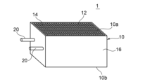
- FIG. 2 is a perspective view showing a schematic configuration of a first honeycomb structure unit constituting the heating element shown in FIG. 1 .
- FIG. 2 is a diagram showing an example of a cross section taken along line III-III of FIG.
- FIG. 2 is a diagram showing an example of a cross section of the heating element shown in FIG. 1 .
- FIG. 11 is a cross-sectional view showing a schematic configuration of a modified example of the honeycomb structure unit.
- FIG. 4 is a cross-sectional view illustrating a schematic configuration of a heating element according to a second embodiment of the present invention.
- the heating element according to an embodiment of the present invention comprises a plurality of honeycomb structure units.
- Fig. 1 is a schematic diagram of the general configuration of a heating element according to a first embodiment of the present invention, as viewed from above.
- Fig. 2 is a perspective view showing the general configuration of a first honeycomb structure unit constituting the heating element shown in Fig. 1.
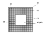
- Fig. 3 is a diagram showing an example of a cross section taken along line III-III in Fig. 1.
- Fig. 4 is a diagram showing an example of a cross section of the heating element shown in Fig. 1.
- the heating element 100 comprises a first honeycomb structure unit 1 and a second honeycomb structure unit 2.
- the first honeycomb structure unit 1 and the second honeycomb structure unit 2 each have a honeycomb structure section 10 that can generate heat when electricity is passed through it, and a pair of electrode sections 20, 20 that heat the honeycomb structure section 10 by passing electricity through it.
- the first honeycomb structure unit 1 has a honeycomb structure portion 10 and a pair of electrode portions 20, 20.
- the honeycomb structure portion 10 has partition walls 14 that extend (in the length direction) from the first end face 10a to the second end face 10b and define a plurality of cells 12 that can serve as fluid flow paths, and an outer peripheral wall 16 that is located on the outer periphery and surrounds the partition walls 14.
- FIG. 2 shows the first honeycomb structure unit 1 shown in FIG. 1 as a representative example, but the second honeycomb structure unit 2 has a similar configuration.
- the first honeycomb structure unit 1 and the second honeycomb structure unit 2 are arranged so that the extension direction (length direction) of the cells 12 of each honeycomb structure part 10 is aligned.
- the arrows in FIG. 1 indicate the direction of fluid flow.
- the fluid that has passed through the first honeycomb structure unit 1 can pass through the second honeycomb structure unit 2.
- the first honeycomb structure unit 1 and the second honeycomb structure unit 2 are arranged at a distance.
- the heating element 100 has an insulating section 30 formed between the first honeycomb structure unit 1 and the second honeycomb structure unit 2.
- the fluid that has passed through the first honeycomb structure unit 1 passes through the insulating section 30 formed between the first honeycomb structure unit 1 and the second honeycomb structure unit 2, and passes through the second honeycomb structure unit 2.
- the heating element has two honeycomb structure units, but it may have three or more honeycomb structure units.
- an insulating section 30 may be provided in advance on the end face of the second honeycomb structure unit 2 on the side where the first honeycomb structure unit 1 is not arranged, and another honeycomb structure unit may be provided via this insulating section 30.
- Three or more honeycomb structure units may be arranged with the extension directions of the respective cells aligned.
- Three or more honeycomb structure units may be arranged spaced apart from each other.
- the heating element can have extremely excellent heat generation characteristics. Specifically, the energy applied to each honeycomb structure unit can be efficiently used to raise the temperature of the honeycomb structure parts that serve as the fluid flow paths. Normally, a temperature difference occurs between the upstream and downstream sides of the honeycomb structure parts of the fluid (for example, the downstream side may be hotter than the upstream side), but in each honeycomb structure unit, the temperature of the fluid flow path can be well controlled. Also, it is possible to prevent short circuits between the honeycomb structure parts, and to prevent malfunctions such as damage to the device or circuit that supplies power to the heating element. In addition, by arranging multiple honeycomb structure parts through insulating parts, the shape of the resulting heating element can be adjusted depending on the application.
- the outer peripheral wall 16 of the honeycomb structure section 10 extends in the length direction.
- Each of the multiple cells 12 is a space extending in the length direction.
- the cross-sectional shape of each cell 12 perpendicular to the length direction is a rectangle in the illustrated example, but may be another polygon, or may be another shape such as a circle.
- the thickness of the partition walls 14 is, for example, 70 ⁇ m to 500 ⁇ m.
- the number of cells 12 per unit area in a plane perpendicular to the extension direction of the cells 12 is, for example, 15 cells/cm 2 to 150 cells/cm 2.
- the thickness of the partition walls 14 and the number of the cells 12 can be measured, for example, by a digital microscope.
- the aperture ratio of the honeycomb structure section 10 is, for example, 65% to 90%.
- the aperture ratio of the honeycomb structure section 10 refers to the aperture ratio per unit area in a plane perpendicular to the extension direction of the cells 12 of the honeycomb structure section 10.
- the aperture ratio of the honeycomb structure section 10 is the ratio of the sum of the areas of the void portions of the cells 12 to the total area of the plane perpendicular to the extension direction of the cells 12 of the honeycomb structure section 10.
- the aperture ratio of the honeycomb structure section 10 can be measured, for example, by a digital microscope.
- the hydraulic diameter of the cells 12 of the honeycomb structure section 10 is, for example, 0.7 mm to 1.8 mm.
- the hydraulic diameter of the cells 12 of the honeycomb structure section 10 is calculated based on the circumferential length (unit: mm) surrounded by the partition walls 14 and the cross-sectional area (unit: mm 2 ) of the cells 12 by the formula: 4 ⁇ (cross-sectional area)/(circumferential length).
- the circumferential length surrounded by the partition walls 14 and the cross-sectional area of the cells 12 can be measured, for example, by a digital microscope.
- the cross-sectional shape of the outer peripheral wall 16 perpendicular to the length direction is a rectangle, but it may be another polygon, or may be another shape such as a circle.
- the thickness of the outer peripheral wall 16 is, for example, 0.5 mm to 5 mm.
- the honeycomb structure parts of the two honeycomb structure units that make up the heating element have the same shape and size, but the heating element may also be made up of multiple honeycomb structure unit parts having different shapes and sizes.
- the thickness of the outer peripheral wall 16 can be measured, for example, by a digital microscope.
- the pair of electrode parts 20, 20 are provided on the outer peripheral wall 16 of the honeycomb structure part 10.
- Each of the pair of electrode parts 20, 20 may be composed of an electrode terminal, one electrode terminal may be connected to the positive pole of a power source, and the other electrode terminal may be connected to the negative pole of the power source.
- the pair of electrode parts 20, 20 are arranged on one side of the center of the honeycomb structure part 10. This arrangement can provide excellent assembly of the heating element. It can also contribute to space saving when installing the heating element.
- the arrangement of the pair of electrode parts 20, 20 is not particularly limited.
- the pair of electrode parts 20, 20 may be arranged on either side of the center of the honeycomb structure part 10 when the honeycomb structure part 10 is viewed from the direction in which the cells 12 extend.
- a cylindrical electrode terminal is provided as the electrode section 20, but the shape and size of the electrode terminal are not particularly limited.
- the electrode terminal may be shaped like a rectangular column or a comb tooth.
- the electrode section 20 may be constructed by forming an electrode layer (not illustrated) on the outer peripheral wall 16 of the honeycomb structure section 10 and providing an electrode terminal via this electrode layer.
- the thickness of the electrode layer is, for example, 100 ⁇ m to 5 mm.
- the insulating section 30 may be provided with an insulating member 31 made of an insulating material.
- the insulating member 31 is arranged in contact with the first honeycomb structure unit 1 and the second honeycomb structure unit 2, for example, from the viewpoint of space saving.
- the insulating member 31 is preferably joined to the first honeycomb structure unit 1 and the second honeycomb structure unit 2.
- the joining method of the insulating member 31 is not particularly limited.
- the insulating member 31 may be joined to the honeycomb structure unit using an adhesive material or joining parts.
- the insulating member 31 may be formed integrally when the honeycomb structure unit (honeycomb structure section 10) is manufactured.
- the insulating section 30 may have a region 40 where the honeycomb structure section 10 of the first honeycomb structure unit 1 does not overlap with the insulating member 31.
- a region 40 where the insulating member 31 does not exist is formed in the center of the honeycomb structure section 10 of the first honeycomb structure unit 1.
- the insulating section 30 has a space 42 surrounded by the inner wall 38 of the insulating member 31.
- the insulating member 31 has partition walls 34 that extend (in the length direction) from the first end face 31a to the second end face 31b and define a number of cells 32 that can serve as fluid flow paths, and an outer peripheral wall 36 that is located on the periphery and surrounds the partition walls 34.
- the insulating member 31 is arranged so that the extension direction of its cells 32 is aligned with the extension direction of the cells 12 of the first honeycomb structure unit 1 and the extension direction of the cells 12 of the second honeycomb structure unit 2.
- the insulating member 31 has a honeycomb structure, which can reduce pressure loss caused by fluid passing through the insulating section 30. Note that the details of the honeycomb structure of the insulating member 31 can be explained in the same manner as for the honeycomb structure section 10 described above.
- the opening ratio of the honeycomb structure portion 10 described above can be designed to be smaller than the opening ratio of the insulating member 31. Specifically, from the viewpoint of ensuring the contact area with the fluid, the opening ratio of the honeycomb structure portion 10 can be designed to be small. On the other hand, from the viewpoint of reducing the pressure loss caused by the fluid passing through the insulating portion 30, the opening ratio of the insulating member 31 can be designed to be large.
- the opening ratio of the insulating member 31 is preferably 70% to 92%.
- the opening ratio of the insulating member 31 refers to the opening ratio per unit area in a plane perpendicular to the extension direction of the cells 32 of the insulating member 31.
- the opening ratio of the insulating member 31 is the ratio of the sum of the areas of the void portions of the cells 32 to the total area of the plane perpendicular to the extension direction of the cells 32 of the insulating member 31.
- the aperture ratio of the insulating member 31 is the ratio of the total area of the gaps in the cells 32 to the area of the region surrounded by the outer wall 36 excluding the space 42 in a plane perpendicular to the extension direction of the cells 32 of the insulating member 31.
- the hydraulic diameter of the cells 12 of the honeycomb structure section 10 described above can be designed to be smaller than the hydraulic diameter of the cells 32 of the insulating member 31.
- the hydraulic diameter of the cells 12 of the honeycomb structure section 10 can be designed to be small.
- the hydraulic diameter of the cells 32 of the insulating member 31 can be designed to be large.
- the hydraulic diameter of the cells 32 of the insulating member 31 is preferably 0.9 mm to 2 mm.
- the hydraulic diameter of the cells 32 of the insulating member 31 is calculated based on the perimeter (unit: mm) surrounded by the partition walls 34 and the cross-sectional area (unit: mm 2 ) of the cells 32 by the formula: 4 ⁇ (cross-sectional area)/(perimeter).
- FIG. 5 is a cross-sectional view showing the schematic configuration of a modified honeycomb structure unit.
- the honeycomb structure section 10 has a first slit 17 and a second slit 18.
- the first slit 17 extends from the first portion P1 of the outer peripheral wall 16 (the side surface of the honeycomb structure section 10) facing each other toward the second portion P2.
- the second slit 18 extends from the second portion P2 of the outer peripheral wall 16 facing each other toward the first portion P1.
- Such a slit can function as an electrical insulator.
- first slit 17 By forming the first slit 17 from the first portion P1 located between the pair of electrode sections 20, 20, it is possible to effectively prevent a short circuit between the pair of electrode sections 20, 20, and the honeycomb structure section 10 can generate heat stably.
- second slit 18 located between the adjacent first slits 17, 17, it is possible to generate heat more uniformly throughout the honeycomb structure section 10.
- the volume resistivity of the honeycomb structure section 10 is, for example, 0.001 ⁇ cm or more, preferably 0.01 ⁇ cm or more, and more preferably 0.1 ⁇ cm or more. Such a volume resistivity can suppress problems such as excessive current flow depending on the applied voltage.
- the volume resistivity of the honeycomb structure section 10 is, for example, 200 ⁇ cm or less, and preferably 100 ⁇ cm or less. Such a volume resistivity can generate sufficient heat when electricity is passed through it.
- the volume resistivity can be a value measured at a temperature of 25°C using the four-terminal method.
- the honeycomb structure 10 is preferably made of ceramics. By using ceramics, the volume resistivity can be satisfactorily satisfied. Ceramics also have a low thermal expansion coefficient and excellent shape stability.
- the honeycomb structure 10 is made of a material that contains, for example, silicon carbide.
- the honeycomb structure 10 is preferably made of a material that contains, as its main component, a silicon carbide material or a silicon-silicon carbide composite material.
- "containing as its main component” means that it contains, for example, 80% by mass or more, and preferably 90% by mass or more.
- the silicon carbide material may be a material impregnated with silicon (silicon-impregnated silicon carbide).
- the silicon-silicon carbide composite material may be a material in which a plurality of silicon carbide particles are bonded together by metallic silicon.
- the silicon carbide particles may function as aggregates, and the silicon may function as a binder.
- the honeycomb structure 10 can be obtained by drying and firing a molded body obtained by molding a molding material containing ceramic raw materials.
- the molding material can contain silicon carbide (e.g., silicon carbide powder) and metallic silicon (e.g., metallic silicon powder).
- Other raw materials that can be contained in the molding material include, for example, a binder, a dispersion medium, and additives.
- the honeycomb structure 10 can be used as a catalyst carrier, and a catalyst can be supported on the partition walls 14.
- a catalyst can be supported on the partition walls 14.
- the catalyst may preferably contain a precious metal (e.g., platinum, rhodium, palladium, ruthenium, indium, silver, gold), aluminum, nickel, zirconium, titanium, cerium, cobalt, manganese, zinc, copper, tin, iron, niobium, magnesium, lanthanum, samarium, bismuth, barium, or a combination thereof.
- the volume resistivity of the electrode portion 20 varies depending on its configuration and constituent materials, but is typically 1 ⁇ 10 ⁇ 6 ⁇ cm to 10 ⁇ cm, and preferably 0.01 ⁇ cm to 10 ⁇ cm.
- the electrode portion 20 may be made of any suitable material.
- the material of the electrode portion 20 include metals, conductive ceramics, and composites (cermets) of metals and conductive ceramics.
- metals include Cr, Fe, Co, Ni, Si, and Ti. These may be used alone or in combination of two or more. When used in combination of two or more, an alloy of two or more metals may be used.
- conductive ceramics include metal compounds such as silicon carbide (SiC); metal silicides such as tantalum silicide (TaSi 2 ) and chromium silicide (CrSi 2 ).
- composites (cermets) of metals and conductive ceramics include composites of metal silicon and silicon carbide, and composites of the above metal silicides, metal silicon, and silicon carbide.
- composite materials (cermets) of metals and conductive ceramics include composite materials in which one or more of the above-mentioned metals are added with one or more of insulating ceramics such as alumina, mullite, zirconia, cordierite, silicon nitride, and aluminum nitride from the viewpoint of reducing thermal expansion.
- the shape of the electrode terminal is preferably comb-shaped. If the material of the electrode terminal is conductive ceramics or a composite material (cermet) of metal and conductive ceramics, the shape of the electrode terminal is preferably cylindrical or prismatic. If the material of the electrode terminal is conductive ceramics or a composite material (cermet) of metal and conductive ceramics, a metal part may be joined to each of its two ends. The ceramic electrode terminal and the metal part can be joined, for example, by crimping, welding, or using a conductive adhesive. Examples of materials for the metal parts include conductive metals such as iron alloys and nickel alloys.
- the electrode section 20 is made of the same material as the honeycomb structure section 10. This configuration reduces the difference in thermal expansion coefficient between the honeycomb structure section 10 and the electrode section 20, and increases the bonding strength between them. This can also contribute to improving productivity.
- the volume resistivity of the electrode section 20 can also be controlled by adjusting its porosity.
- the volume resistivity of the insulating member 31 is preferably 1 ⁇ 10 ⁇ cm or more, and more preferably 1 ⁇ 10 ⁇ cm or more. On the other hand, the volume resistivity of the insulating member 31 is, for example, 1 ⁇ 10 ⁇ cm or less.
- the insulating member 31 may be made of any suitable material that satisfies the above volume resistivity.
- the insulating member 31 is preferably made of ceramics. By using ceramics, the above volume resistivity can be satisfactorily satisfied. Ceramics also have a low thermal expansion coefficient and can have excellent shape stability. Furthermore, by using ceramics, the difference in thermal expansion coefficient with the honeycomb structure portion 10 can be reduced, and thermal shock resistance can be improved. Examples of ceramics include cordierite, mullite, alumina, spinel, silicon carbide, silicon nitride, and aluminum titanate. These can be used alone or in combination of two or more types.
- a catalyst may be supported on the partition 34 of the insulating member 31.
- CO, NO x , hydrocarbons, and the like in the fluid (e.g., gas) passing through the cell 32 can be converted into harmless substances by catalytic reaction.
- specific examples of the catalyst are as described above.
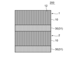
- FIG. 6 is a cross-sectional view showing a schematic configuration of a heating element according to a second embodiment of the present invention.
- the heating element 200 differs from the heating element 100 of the first embodiment in that the insulating portion 30 does not have a space 42 (the inner peripheral wall 38 of the insulating member 31).
- the heating element 200 differs from the heating element 100 of the first embodiment in that, when the first honeycomb structure unit 1 is viewed from the extension direction of the cells 12, the insulating portion 30 does not have a region 40 formed therein where the honeycomb structure portion 10 of the first honeycomb structure unit 1 does not overlap with the insulating member 31.
- the absence of a space 42 in the insulating portion 30 can provide excellent mechanical strength. Furthermore, there are cases where even better insulation can be achieved.
- the present invention is not limited to the above-described embodiment, and various modifications are possible.
- the configurations shown in the above-described embodiments can be replaced with configurations that are substantially the same as those shown in the above-described embodiments, that have the same effects, or that can achieve the same purpose.
- the heating element of the embodiment of the present invention can be used, for example, as a catalyst carrier that supports a catalyst.
- honeycomb structure unit 1 honeycomb structure unit, 2 honeycomb structure unit, 10 honeycomb structure portion, 12 cell, 14 partition wall, 16 outer peripheral wall, 17 first slit, 18 second slit, 20 electrode portion, 30 insulating portion, 31 insulating member, 32 cell, 34 partition wall, 36 outer peripheral wall, 42 space portion, 100 heating element, 200 heating element.
Landscapes
- Exhaust Gas Treatment By Means Of Catalyst (AREA)
- Catalysts (AREA)
- Exhaust Gas After Treatment (AREA)
Priority Applications (2)
| Application Number | Priority Date | Filing Date | Title |
|---|---|---|---|
| JP2024559993A JPWO2024111259A1 (https=) | 2022-11-21 | 2023-10-05 | |
| EP23894271.8A EP4559575A1 (en) | 2022-11-21 | 2023-10-05 | Heating element |
Applications Claiming Priority (2)
| Application Number | Priority Date | Filing Date | Title |
|---|---|---|---|
| JP2022-185922 | 2022-11-21 | ||
| JP2022185922 | 2022-11-21 |
Publications (1)
| Publication Number | Publication Date |
|---|---|
| WO2024111259A1 true WO2024111259A1 (ja) | 2024-05-30 |
Family
ID=91195423
Family Applications (1)
| Application Number | Title | Priority Date | Filing Date |
|---|---|---|---|
| PCT/JP2023/036367 Ceased WO2024111259A1 (ja) | 2022-11-21 | 2023-10-05 | 発熱体 |
Country Status (3)
| Country | Link |
|---|---|
| EP (1) | EP4559575A1 (https=) |
| JP (1) | JPWO2024111259A1 (https=) |
| WO (1) | WO2024111259A1 (https=) |
Citations (7)
| Publication number | Priority date | Publication date | Assignee | Title |
|---|---|---|---|---|
| JPH03246315A (ja) * | 1990-02-23 | 1991-11-01 | Nissan Motor Co Ltd | 触媒コンバータ |
| JP2001293377A (ja) * | 2000-04-13 | 2001-10-23 | Nippon Yakin Kogyo Co Ltd | 自己発熱可能なメタルハニカム構造体 |
| JP2005194935A (ja) * | 2004-01-07 | 2005-07-21 | Isuzu Motors Ltd | 排気ガス浄化装置 |
| JP2011098306A (ja) * | 2009-11-06 | 2011-05-19 | Gifu Univ | 揮発性有機化合物処理装置 |
| JP2016001529A (ja) * | 2014-06-11 | 2016-01-07 | 東海高熱工業株式会社 | 発熱構造体 |
| JP2022053219A (ja) * | 2020-09-24 | 2022-04-05 | イビデン株式会社 | 電気加熱式触媒 |
| JP2022109861A (ja) * | 2021-01-15 | 2022-07-28 | 日本碍子株式会社 | セラミックス体及びその製造方法、ヒーターエレメント、ヒーターユニット、ヒーターシステム並びに浄化システム |
Family Cites Families (2)
| Publication number | Priority date | Publication date | Assignee | Title |
|---|---|---|---|---|
| JP5193922B2 (ja) * | 2009-03-30 | 2013-05-08 | 日本碍子株式会社 | 排ガス浄化処理装置 |
| JP2020143662A (ja) * | 2019-01-09 | 2020-09-10 | マレリ株式会社 | 触媒コンバータ及び電熱触媒用電極カバー |
-
2023
- 2023-10-05 JP JP2024559993A patent/JPWO2024111259A1/ja active Pending
- 2023-10-05 EP EP23894271.8A patent/EP4559575A1/en active Pending
- 2023-10-05 WO PCT/JP2023/036367 patent/WO2024111259A1/ja not_active Ceased
Patent Citations (7)
| Publication number | Priority date | Publication date | Assignee | Title |
|---|---|---|---|---|
| JPH03246315A (ja) * | 1990-02-23 | 1991-11-01 | Nissan Motor Co Ltd | 触媒コンバータ |
| JP2001293377A (ja) * | 2000-04-13 | 2001-10-23 | Nippon Yakin Kogyo Co Ltd | 自己発熱可能なメタルハニカム構造体 |
| JP2005194935A (ja) * | 2004-01-07 | 2005-07-21 | Isuzu Motors Ltd | 排気ガス浄化装置 |
| JP2011098306A (ja) * | 2009-11-06 | 2011-05-19 | Gifu Univ | 揮発性有機化合物処理装置 |
| JP2016001529A (ja) * | 2014-06-11 | 2016-01-07 | 東海高熱工業株式会社 | 発熱構造体 |
| JP2022053219A (ja) * | 2020-09-24 | 2022-04-05 | イビデン株式会社 | 電気加熱式触媒 |
| JP2022109861A (ja) * | 2021-01-15 | 2022-07-28 | 日本碍子株式会社 | セラミックス体及びその製造方法、ヒーターエレメント、ヒーターユニット、ヒーターシステム並びに浄化システム |
Also Published As
| Publication number | Publication date |
|---|---|
| EP4559575A1 (en) | 2025-05-28 |
| JPWO2024111259A1 (https=) | 2024-05-30 |
Similar Documents
| Publication | Publication Date | Title |
|---|---|---|
| JP5692198B2 (ja) | ハニカム構造体 | |
| US10280819B2 (en) | Honeycomb-type heating device and method of using same | |
| CN104364483B (zh) | 可电加热的蜂窝体的多个金属片层的电连接和相应的蜂窝体 | |
| EP3574984B1 (en) | Electrically heated catalyst device | |
| JP2014054934A (ja) | ヒーター | |
| US10287942B2 (en) | Honeycomb type heating device and method for using the same | |
| US9962652B2 (en) | Honeycomb type heating device and method of using the same | |
| CN110354911A (zh) | 电加热型催化剂用载体以及废气净化装置 | |
| JP5531925B2 (ja) | 電気加熱型触媒 | |
| JP2013158714A (ja) | 電気加熱式触媒装置 | |
| WO2024111259A1 (ja) | 発熱体 | |
| CN113756914B (zh) | 电加热式催化剂装置 | |
| EP4559576A1 (en) | Heating element | |
| JP6093130B2 (ja) | ヒーター | |
| JP3119280B2 (ja) | 加熱式ハニカム構造体 | |
| JP2025154849A (ja) | ハニカム構造体及びハニカムヒータ | |
| CN115199385B (zh) | 催化剂装置 | |
| JP2025154855A (ja) | 三相型ハニカムヒータ | |
| KR102292906B1 (ko) | 히터 코어, 히터 및 이를 포함하는 히팅 시스템 | |
| CN115111028B (zh) | 电加热式催化剂装置及其制造方法 | |
| KR100581182B1 (ko) | 허니컴히터 | |
| JP7146439B2 (ja) | プラズマリアクタ | |
| JP2024075356A (ja) | 電気加熱式担体 | |
| JP2022135885A (ja) | ハニカム構造体、電気加熱式担体及び排気ガス浄化装置 | |
| JP2022093013A (ja) | 電気加熱型担体及び排気ガス浄化装置 |
Legal Events
| Date | Code | Title | Description |
|---|---|---|---|
| 121 | Ep: the epo has been informed by wipo that ep was designated in this application |
Ref document number: 23894271 Country of ref document: EP Kind code of ref document: A1 |
|
| WWE | Wipo information: entry into national phase |
Ref document number: 2024559993 Country of ref document: JP |
|
| WWE | Wipo information: entry into national phase |
Ref document number: 2023894271 Country of ref document: EP |
|
| ENP | Entry into the national phase |
Ref document number: 2023894271 Country of ref document: EP Effective date: 20250221 |
|
| WWP | Wipo information: published in national office |
Ref document number: 2023894271 Country of ref document: EP |
|
| NENP | Non-entry into the national phase |
Ref country code: DE |
|
| WWW | Wipo information: withdrawn in national office |
Ref document number: 2023894271 Country of ref document: EP |