WO2024111127A1 - 車体用繊維強化樹脂材 - Google Patents
車体用繊維強化樹脂材 Download PDFInfo
- Publication number
- WO2024111127A1 WO2024111127A1 PCT/JP2022/043627 JP2022043627W WO2024111127A1 WO 2024111127 A1 WO2024111127 A1 WO 2024111127A1 JP 2022043627 W JP2022043627 W JP 2022043627W WO 2024111127 A1 WO2024111127 A1 WO 2024111127A1
- Authority
- WO
- WIPO (PCT)
- Prior art keywords
- fiber
- resin material
- reinforcing fiber
- reinforced resin
- reinforcing
- Prior art date
- Legal status (The legal status is an assumption and is not a legal conclusion. Google has not performed a legal analysis and makes no representation as to the accuracy of the status listed.)
- Ceased
Links
Images


Classifications
-
- B—PERFORMING OPERATIONS; TRANSPORTING
- B29—WORKING OF PLASTICS; WORKING OF SUBSTANCES IN A PLASTIC STATE IN GENERAL
- B29C—SHAPING OR JOINING OF PLASTICS; SHAPING OF MATERIAL IN A PLASTIC STATE, NOT OTHERWISE PROVIDED FOR; AFTER-TREATMENT OF THE SHAPED PRODUCTS, e.g. REPAIRING
- B29C43/00—Compression moulding, i.e. applying external pressure to flow the moulding material; Apparatus therefor
- B29C43/02—Compression moulding, i.e. applying external pressure to flow the moulding material; Apparatus therefor of articles of definite length, i.e. discrete articles
- B29C43/20—Making multilayered or multicoloured articles
-
- B—PERFORMING OPERATIONS; TRANSPORTING
- B29—WORKING OF PLASTICS; WORKING OF SUBSTANCES IN A PLASTIC STATE IN GENERAL
- B29C—SHAPING OR JOINING OF PLASTICS; SHAPING OF MATERIAL IN A PLASTIC STATE, NOT OTHERWISE PROVIDED FOR; AFTER-TREATMENT OF THE SHAPED PRODUCTS, e.g. REPAIRING
- B29C70/00—Shaping composites, i.e. plastics material comprising reinforcements, fillers or preformed parts, e.g. inserts
- B29C70/04—Shaping composites, i.e. plastics material comprising reinforcements, fillers or preformed parts, e.g. inserts comprising reinforcements only, e.g. self-reinforcing plastics
- B29C70/06—Fibrous reinforcements only
- B29C70/10—Fibrous reinforcements only characterised by the structure of fibrous reinforcements, e.g. hollow fibres
-
- B—PERFORMING OPERATIONS; TRANSPORTING
- B29—WORKING OF PLASTICS; WORKING OF SUBSTANCES IN A PLASTIC STATE IN GENERAL
- B29C—SHAPING OR JOINING OF PLASTICS; SHAPING OF MATERIAL IN A PLASTIC STATE, NOT OTHERWISE PROVIDED FOR; AFTER-TREATMENT OF THE SHAPED PRODUCTS, e.g. REPAIRING
- B29C70/00—Shaping composites, i.e. plastics material comprising reinforcements, fillers or preformed parts, e.g. inserts
- B29C70/04—Shaping composites, i.e. plastics material comprising reinforcements, fillers or preformed parts, e.g. inserts comprising reinforcements only, e.g. self-reinforcing plastics
- B29C70/28—Shaping operations therefor
- B29C70/40—Shaping or impregnating by compression not applied
-
- B—PERFORMING OPERATIONS; TRANSPORTING
- B32—LAYERED PRODUCTS
- B32B—LAYERED PRODUCTS, i.e. PRODUCTS BUILT-UP OF STRATA OF FLAT OR NON-FLAT, e.g. CELLULAR OR HONEYCOMB, FORM
- B32B27/00—Layered products comprising a layer of synthetic resin
- B32B27/18—Layered products comprising a layer of synthetic resin characterised by the use of special additives
- B32B27/20—Layered products comprising a layer of synthetic resin characterised by the use of special additives using fillers, pigments, thixotroping agents
-
- B—PERFORMING OPERATIONS; TRANSPORTING
- B32—LAYERED PRODUCTS
- B32B—LAYERED PRODUCTS, i.e. PRODUCTS BUILT-UP OF STRATA OF FLAT OR NON-FLAT, e.g. CELLULAR OR HONEYCOMB, FORM
- B32B5/00—Layered products characterised by the non- homogeneity or physical structure, i.e. comprising a fibrous, filamentary, particulate or foam layer; Layered products characterised by having a layer differing constitutionally or physically in different parts
- B32B5/22—Layered products characterised by the non- homogeneity or physical structure, i.e. comprising a fibrous, filamentary, particulate or foam layer; Layered products characterised by having a layer differing constitutionally or physically in different parts characterised by the presence of two or more layers which are next to each other and are fibrous, filamentary, formed of particles or foamed
- B32B5/24—Layered products characterised by the non- homogeneity or physical structure, i.e. comprising a fibrous, filamentary, particulate or foam layer; Layered products characterised by having a layer differing constitutionally or physically in different parts characterised by the presence of two or more layers which are next to each other and are fibrous, filamentary, formed of particles or foamed one layer being a fibrous or filamentary layer
- B32B5/28—Layered products characterised by the non- homogeneity or physical structure, i.e. comprising a fibrous, filamentary, particulate or foam layer; Layered products characterised by having a layer differing constitutionally or physically in different parts characterised by the presence of two or more layers which are next to each other and are fibrous, filamentary, formed of particles or foamed one layer being a fibrous or filamentary layer impregnated with or embedded in a plastic substance
-
- C—CHEMISTRY; METALLURGY
- C08—ORGANIC MACROMOLECULAR COMPOUNDS; THEIR PREPARATION OR CHEMICAL WORKING-UP; COMPOSITIONS BASED THEREON
- C08J—WORKING-UP; GENERAL PROCESSES OF COMPOUNDING; AFTER-TREATMENT NOT COVERED BY SUBCLASSES C08B, C08C, C08F, C08G or C08H
- C08J5/00—Manufacture of articles or shaped materials containing macromolecular substances
- C08J5/04—Reinforcing macromolecular compounds with loose or coherent fibrous material
Definitions
- the present invention relates to a fiber reinforced plastic member for a vehicle body.
- Patent Document 1 discloses a carbon fiber reinforced resin material.
- the carbon fiber reinforced resin material disclosed in Patent Document 1 multiple thin carbon fiber layers formed by tow spreading are laminated within the matrix resin.
- the carbon fiber bundles used in carbon fiber reinforced resin are made up of a very large number of filaments and usually have a circular or elliptical cross section.
- the fiber bundles are also called tows, and carbon fiber filaments with a diameter of 4 to 7 ⁇ m are often used for carbon fiber tows.
- Tows are classified by the number of filaments, such as 12k or 24k.
- a 12k tow is composed of 12,000 filaments.
- a relatively thin tow of 24k or less is usually called a regular tow, and a thick tow of 40k or more is called a large tow.
- Spread tow technology is a technique for spreading the tow filaments thinly and evenly, and large tow is usually used.
- the mechanical properties such as the strength and elastic modulus (hardness) of the carbon fiber reinforced resin material can be improved, as described in Patent Document 1.
- the object of the present invention is to provide a fiber-reinforced plastic material for vehicle bodies that can improve productivity while improving mechanical properties.
- the fiber-reinforced resin material for vehicle bodies comprises a plurality of first reinforcing fiber layers formed from unspread reinforcing fiber bundles, a second reinforcing fiber layer group in which a plurality of second reinforcing fiber layers formed from spread reinforcing fiber bundles are continuously laminated, and a matrix resin that is impregnated into the first and second reinforcing fiber layers and is reinforced by the first and second reinforcing fiber layers.
- the region on the inside of the bend with respect to the central plane of the thickness of the fiber-reinforced resin material is the compression side region where compressive stress acts, and the region on the outside of the bend is the tension side region where tensile stress acts.
- the second reinforcing fiber layer group is arranged in the tension side region.
- the fiber-reinforced resin material for vehicle bodies comprises a plurality of first reinforcing fiber layers formed from unspread reinforcing fiber bundles, a second reinforcing fiber layer group in which a plurality of second reinforcing fiber layers formed from spread reinforcing fiber bundles are continuously laminated, and a matrix resin that is impregnated into the first and second reinforcing fiber layers and is reinforced by the first and second reinforcing fiber layers.
- the region on the inside of the bend with respect to the central plane of the thickness of the fiber-reinforced resin material is the compression side region where compressive stress acts, and the region on the outside of the bend is the tension side region where tensile stress acts.
- the second reinforcing fiber layer group is arranged in the compression side region.
- the first feature described above allows the number of layers of the thin second reinforcing fiber layer to be reduced, improving productivity, while improving the strength of the fiber-reinforced resin material through the second reinforcing fiber layer group.
- the second feature described above reduces the number of layers of the thin second reinforcing fiber layer, improving productivity, while improving the hardness of the fiber-reinforced resin material by using the second reinforcing fiber layer group.
- FIG. 1 is a schematic perspective view for explaining fiber spreading.
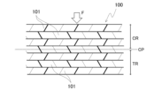
- FIG. 2 is a partial cross-sectional view of a fiber-reinforced resin material for explaining the tensile/compression side region.
- FIG. 3 is a schematic partial cross-sectional view of the fiber reinforced resin material according to the first embodiment.
- FIG. 4 is a schematic partial cross-sectional view of a fiber-reinforced resin material according to the second embodiment.
- FIG. 5 is a schematic partial cross-sectional view of a fiber reinforced resin material according to a third embodiment.
- Spreading is a technique for long-fiber reinforced fibers, and is not used for short-fiber reinforced fibers.
- Long-fiber reinforced fibers that have not been spread are in the state of a fiber bundle 11 in which many filaments 10 are bundled together, that is, a tow 11, as shown on the left side of Figure 1.
- the tow 11 contains several thousand to tens of thousands of filaments.
- Figure 1 is a schematic diagram, and the number of filaments 10 is not accurate.
- the cross section of an unspread tow 11 is circular or elliptical.
- the technique of spreading this flat to make a tow 12 as shown on the right side of Figure 1 is called spreading technology, and there are various spreading methods.
- Spread tows 12 may be arranged in parallel to form a unidirectional (UD) reinforced fiber layer, or spread tows 12 may be woven to form a quasi-isotropic reinforced fiber layer. Pseudo-isotropy can also be achieved by stacking multiple tows 12 with crossed unidirectional directions.
- UD unidirectional
- Pseudo-isotropy can also be achieved by stacking multiple tows 12 with crossed unidirectional directions.
- the reinforcing fiber layer in the molded fiber-reinforced resin material is formed from opened fiber bundles (tows) can be determined by observing the thickness of the reinforcing fiber layer and the uniformity of the distribution of the filaments within the reinforcing fiber layer.
- the thickness of the reinforced fiber layer made of the opened tows 12 is thin. This allows the matrix resin to be sufficiently impregnated into the reinforced fiber layer. As a result, resin peeling within the reinforced fiber layer can be suppressed. Furthermore, gaps tend to form when tows 11 with circular cross sections are arranged side by side, but stacking flat tows 12 can also improve the fiber volume content Vf [%] of the reinforcing fibers. As a result, the mechanical properties of the fiber reinforced resin can be improved. Therefore, fiber reinforced resin using opened tows 12 exhibits improved mechanical properties. However, when a fiber reinforced resin material is formed using only opened tows 12, as described above, a greater number of layers is required than for a reinforced fiber layer made of unopened tows 11.
- FIG. 2 shows a typical fiber reinforced resin material 100.
- a load is generated in the in-plane direction in the fiber reinforced resin material 100 by an external force F that bends the fiber reinforced resin material 100, and a compressive force or a tensile force acts on the fiber reinforced resin material 100.
- the external force F acts in the thickness direction of the fiber reinforced resin material 100, that is, in the stacking direction of the reinforced fiber layers 101.
- FIG. 2 also shows a schematic cross section of the fiber reinforced resin material 100, as in FIG. 1.
- FIG. 1 shows a schematic cross section of the fiber reinforced resin material 100, as in FIG. 1.
- each reinforced fiber layer 101 the reinforcing fibers themselves in each reinforced fiber layer 101 are not shown, and the state in which each reinforced fiber layer 101 is impregnated with a matrix resin is shown.
- the matrix resins of each reinforced fiber layer 101 are actually continuous with each other without forming a clear boundary.
- the thermosetting matrix resin first softens (liquefies) before hardening as the hardening reaction progresses. During this process, the clear boundaries between the matrix resins of the prepregs disappear, and the matrix resins become integrated.
- the schematic representations shown in Figures 1 and 2 are also used in Figures 3 to 5, which will be described later.
- the region on the outside of the bend of the fiber reinforced resin material 100 is defined as the tension side region TR where the tensile stress acts.
- the first to third embodiments of the present invention will be described with reference to FIG. 3 to FIG. 5, and the terms “tension side region TR” and “compression side region CR” are as defined herein.
- the fiber-reinforced resin material M is used in a vehicle body.
- Examples of the fiber-reinforced resin material M for a vehicle body include a vehicle body frame structural material and a vehicle body panel material.
- the vehicle body frame structural material is a member that receives a collision load during a vehicle collision. More specifically, examples of the vehicle body frame structural material include front and rear side members, side sills, A/B/C pillars, and roof side rails. More specifically, examples of the vehicle body panel material include the bonnet/hood that covers the engine/motor room at the front of the vehicle body, the trunk lid/hood that covers the trunk room at the rear of the vehicle body, front and rear fenders, door panels, and loop panels.
- Body frame structural materials are components that receive collision loads during a vehicle collision.
- the side member buckles to absorb collision energy during a frontal or rear collision.
- the buckling mode of the side member is controlled by the reinforcing material and beads formed on the side member. That is, depending on the position of the fiber-reinforced resin material M in the side member, it is known how the external force F that bends the fiber-reinforced resin material M during a collision acts on the fiber-reinforced resin material M. Therefore, the "tension side region TR" and “compression side region CR" of the fiber-reinforced resin material M when the external force F that bends the fiber-reinforced resin material M acts on it can be known.
- the side sill or B-pillar secures the passenger compartment, i.e., the survival space, during a side collision. That is, when the external force F during a side collision is taken into consideration, it can be seen that the passenger compartment side of the fiber-reinforced resin material M becomes the "tension side region TR".
- the fiber-reinforced resin material M is an A/C pillar or roof rail
- the A/C pillar or roof rail secures the passenger compartment, i.e., survival space, in the event of a vehicle rollover.
- the passenger compartment side of the fiber-reinforced resin material M becomes the "tensile region TR."
- Body panel materials are primarily components that form the outer panels of a vehicle.
- an external force F acts from outside the vehicle. Luggage may be placed on the bonnet/hood or roof, or people may lean on the fender or door panel. Therefore, when fiber-reinforced resin material M is used as a body panel material, it can be seen that the outer surface side of the body panel material where the external force F acts becomes the "compression side region CR.” If the body panel material bends easily, the sense of quality is compromised.
- the fiber-reinforced resin material M of the first embodiment includes a plurality of first reinforcing fiber layers 1, a second reinforcing fiber layer group 2 in which a plurality of second reinforcing fiber layers 2a are continuously stacked, and a matrix resin.
- Each first reinforcing fiber layer 1 is formed of unopened reinforcing fiber bundles (tows).
- Each second reinforcing fiber layer 2a is formed of opened reinforcing fiber bundles (tows).
- the matrix resin is impregnated into the first reinforcing fiber layer 1 and the second reinforcing fiber layer 2a, and is reinforced by the first reinforcing fiber layer 1 and the second reinforcing fiber layer 2a.
- Each of the first reinforcing fiber layer 1 and the second reinforcing fiber layer 2a may have a unidirectional orientation with the tows arranged in parallel, or may be woven to have pseudo-isotropy. In addition, since these fiber layers are laminated, pseudo-isotropy can also be achieved by crossing the directionality of the stratum corneum.
- the reinforcing fiber in this embodiment is carbon fiber.
- the second reinforcing fiber layer group 2 is formed by continuously laminating the second reinforcing fiber layers 2a formed from opened tows. Therefore, as described above, the second reinforcing fiber layer group 2 has good mechanical properties.
- the second reinforcing fiber layer group 2 is arranged in the tensile side region TR.
- Reinforced fibers particularly carbon fiber reinforced plastic (CFRP) reinforced with the carbon fibers used in this embodiment, can effectively resist tensile forces. Therefore, by arranging the second reinforcing fiber layer group 2 in the tensile side region TR, the bending strength of the fiber reinforced resin material M can be improved.
- the fiber reinforced resin material M of this embodiment can be used as a vehicle body frame structural material.
- the fiber reinforced resin material M is formed using only a large number of second reinforcing fiber layers 2a, but as described above, this increases the number of layers and makes it difficult to improve productivity.
- this embodiment by using the second reinforcing fiber layer group 2 only in a portion and using the first reinforcing fiber layer 1 in the remaining portion, it is possible to minimize the increase in the number of layers and improve productivity, while improving the strength of the fiber reinforced resin material M with the second reinforcing fiber layer group 2.
- the second reinforcing fiber layer group 2 which has a high fiber volume content Vf of carbon fiber, is only used in a portion, it is possible to minimize the increase in the amount of expensive carbon fiber used and suppress the increase in the production cost of the fiber reinforced resin material M.
- the second reinforcing fiber layer group 2 is used as the outermost layer in the tensile side region TR of the fiber reinforced resin material M. Therefore, the second reinforcing fiber layer group 2 can most effectively improve the strength of the fiber reinforced resin material M. Even if it is not the outermost layer, the strength of the fiber reinforced resin material M can be improved as long as the second reinforcing fiber layer group 2 is arranged in the tensile side region TR. However, by arranging the second reinforcing fiber layer group 2 in the outermost layer where the tensile stress in the fiber reinforced resin material M caused by the external force F is the largest, the bending strength of the fiber reinforced resin material M can be most effectively improved.
- the bending strength is improved by using the second reinforcing fiber layer group 2 only in the outermost layer of the tension side region TR as in this embodiment, rather than forming the fiber reinforced resin material M only from a large number of second reinforcing fiber layers 2a.
- the fiber reinforced resin material M is formed only from a large number of second reinforcing fiber layers 2a, layer peeling due to compression failure is likely to occur in the second reinforcing fiber layer 2a in the compression side region CR.
- the strength of the fiber reinforced resin material M can be improved by arranging only the first reinforcing fiber layer 1 in the compression side region CR.
- only a single second reinforcing fiber layer group 2 is arranged in the tension side region TR.
- a single second reinforcing fiber layer group 2 is preferable to reduce the number of layers, it is not prohibited to arrange two or more second reinforcing fiber layer groups 2 in the tension side region TR.
- the following configuration may be used.
- a second reinforcing fiber layer group 2 is arranged in the outermost layer of the tension side region TR, and a first reinforcing fiber layer 1 is arranged adjacent to it on the inside. Then, a second reinforcing fiber layer group 2 is arranged further inside this first reinforcing fiber layer 1.
- the remaining reinforcing fiber layers inside this second second reinforcing fiber layer group 2 and in the compression side region CR are the first reinforcing fiber layers 1.
- FIG. 4 shows a fiber-reinforced resin material M of the second embodiment.
- the second reinforcing fiber layer group 2 is arranged in the compression side region CR.
- Each first reinforcing fiber layer 1 of this embodiment has the same configuration as the first reinforcing fiber layer 1 of the first embodiment.
- Each second reinforcing fiber layer 2a of this embodiment also has the same configuration as the second reinforcing fiber layer 2a of the first embodiment.
- the second reinforcing fiber layer group 2 of this embodiment also has the same configuration as the second reinforcing fiber layer group 2 of the first embodiment. Therefore, a duplicated description of these will be omitted.
- the elastic modulus, i.e., hardness, of the fiber reinforced resin material M can be improved.
- the fiber reinforced resin material M of this embodiment has a bending strength higher than that of a fiber reinforced resin material formed only of a plurality of first reinforcing fiber layers 1 (however, it is lower than the strength of the fiber reinforced resin material M of the first embodiment). It has been found that in order to improve the elastic modulus (hardness) of the fiber reinforced resin material M, it is more effective to arrange the second reinforcing fiber layer group 2 only in the compression side region CR than to arrange it only in the tension side region TR.
- the fiber reinforced resin material M is formed with a large number of second reinforcing fiber layers 2a, the number of layers increases, making it difficult to improve productivity.
- the second reinforcing fiber layer group 2 by using the second reinforcing fiber layer group 2 only in a portion and using the first reinforcing fiber layer 1 in the remaining portion, the increase in the number of layers is minimized to improve productivity, while the second reinforcing fiber layer group 2 can improve the elastic modulus (hardness) of the fiber reinforced resin material M.
- the second reinforcing fiber layer group 2 which has a high fiber volume content Vf of carbon fiber, is only used in a portion of the material, the increase in the amount of expensive carbon fiber used can be minimized, and the increase in the production cost of the fiber reinforced resin material M can be suppressed.
- the second reinforcing fiber layer group 2 is used as the outermost layer in the compression side region CR of the fiber reinforced resin material M. Therefore, the second reinforcing fiber layer group 2 can most effectively improve the elastic modulus (hardness) of the fiber reinforced resin material M. Even if it is not the outermost layer, as long as the second reinforcing fiber layer group 2 is arranged in the tension side region TR, the elastic modulus (hardness) of the fiber reinforced resin material M will be improved. However, by arranging the second reinforcing fiber layer group 2 in the outermost layer, the bending hardness of the fiber reinforced resin material M can be most effectively improved.
- only a single second reinforcing fiber layer group 2 is arranged in the compression side region CR.
- a single second reinforcing fiber layer group 2 is preferable to reduce the number of layers, but two or more second reinforcing fiber layer groups 2 may be arranged in the compression side region CR.
- the following configuration may be used.
- a second reinforcing fiber layer group 2 is arranged in the outermost layer of the compression side region CR, and a first reinforcing fiber layer 1 is arranged adjacent to and on the inside. Then, a second reinforcing fiber layer group 2 is arranged further inside this first reinforcing fiber layer 1.
- the remaining reinforcing fiber layers inside this second second reinforcing fiber layer group 2 and in the tension side region TR are the first reinforcing fiber layers 1.
- FIG. 5 shows a fiber-reinforced resin material M of the third embodiment.
- the second reinforcing fiber layer group 2 is arranged in the tension side region TR and the compression side region CR.
- the flexural modulus (hardness) of the fiber-reinforced resin material M can be improved compared to the case where the second reinforcing fiber layer group 2 is arranged only in the compression side region CR as in the second embodiment.
- the flexural strength of the fiber-reinforced resin material M is inferior to the case where the second reinforcing fiber layer group 2 is arranged only in the tension side region TR as in the first embodiment, but is improved compared to the case where the second reinforcing fiber layer group 2 is arranged only in the compression side region CR as in the second embodiment.
- the reason why the flexural strength of the fiber-reinforced resin material M of this embodiment is lower than that of the first embodiment is because layer peeling due to compression failure is likely to occur in the second reinforcing fiber layer 2a of the second reinforcing fiber layer group 2 in the compression side region CR.
- the arrangement of the second reinforcing fiber layer group 2 as in this embodiment may be effective.
- the second reinforcing fiber layer group 2 is arranged in each of the tension side region TR and the compression side region CR, but this does not prevent an additional second reinforcing fiber layer group 2 from being arranged in addition to these two second reinforcing fiber layer groups 2.
- the second reinforcing fiber layer group 2 is used as the outermost layer in the tension side region TR of the fiber reinforced resin material M, and is also used as the outermost layer in the compression side region CR of the fiber reinforced resin material M. Therefore, the second reinforcing fiber layer group 2 can most effectively improve the elastic modulus (hardness) of the fiber reinforced resin material M, and can also improve the strength to a certain extent, thereby achieving a well-balanced improvement in the mechanical strength of the fiber reinforced resin material M.
- the layer thickness of the second reinforcing fiber layer 2a is preferably 80 ⁇ m or more and 300 ⁇ m or less.
- the second reinforcing fiber layer 2a formed using the opened tows brings about the above-mentioned improvement in mechanical properties by thinly spreading the filaments. If the thickness is less than 80 ⁇ m, the opened tows are too thin, reducing the linearity of the tows and making it easier for gaps to form between the reinforcing fibers during stacking. If gaps are more likely to form, it becomes difficult to obtain the effect of improving the mechanical properties by increasing the fiber volume content Vf.
- the thickness is less than 80 ⁇ m, the number of layers of the second reinforcing fiber layer 2a increases, making it difficult to obtain the effect of improving productivity.
- the thickness exceeds 300 ⁇ m, it becomes difficult to obtain the above-mentioned effect brought about by the thin layering by "opening".
- the reinforcing fibers of the second reinforcing fiber layer 2a are preferably carbon fibers.
- Carbon fibers are lighter than other reinforcing fibers, and therefore can effectively contribute to reducing the weight of the vehicle body.
- Carbon fibers also have superior fatigue resistance, chemical resistance, and corrosion resistance among reinforcing fibers, making them suitable for use in vehicle bodies.
- carbon fibers are also superior in terms of strength, and fiber-spreading techniques are easily applicable.
- FIG. 2 illustrates a case where the external force F that bends the fiber reinforced resin material 100 acts in the thickness direction of the fiber reinforced resin material 100, i.e., in the stacking direction of the reinforced fiber layer 101.
- the direction of the external force F that bends the fiber reinforced resin material M is not limited to the thickness direction or stacking direction.
- the fiber reinforced resin material M may be bent by an external force F from a direction other than the thickness direction or stacking direction. Even in such a case, the "tension side region TR" and the "compression side region CR" can be defined by taking into account the bending form (inside/outside bending) of the fiber reinforced resin material M.
- the reinforcing fibers of the first reinforcing fiber layer 1 and the second reinforcing fiber layer 2a are carbon fibers.
- the reinforcing fibers of the second reinforcing fiber layer 2a are preferably carbon fibers, but the reinforcing fibers of the first reinforcing fiber layer 1 and the second reinforcing fiber layer 2a are not limited to carbon fibers.
- Other reinforcing fibers such as glass fibers, aramid fibers, boron fibers, Kevlar fibers, and natural fibers may be used.
- the type of matrix resin of the fiber-reinforced resin material M is also not limited, and may be, for example, a thermosetting resin or a thermoplastic resin as described above.
- the molding method of the fiber-reinforced resin material M is also not limited, and various molding methods using long reinforcing fibers, such as autoclave molding using prepregs and RTM formation, can be used.
- Fiber reinforced resin material 1 First reinforcing fiber layer 2a Second reinforcing fiber layer 2 Second reinforcing fiber layer group CP Central plane TR (in the thickness direction of the fiber reinforced resin material M) Tension side region CR Compression side region F External force
Landscapes
- Chemical & Material Sciences (AREA)
- Engineering & Computer Science (AREA)
- Mechanical Engineering (AREA)
- Composite Materials (AREA)
- Manufacturing & Machinery (AREA)
- Materials Engineering (AREA)
- Health & Medical Sciences (AREA)
- Chemical Kinetics & Catalysis (AREA)
- Medicinal Chemistry (AREA)
- Polymers & Plastics (AREA)
- Organic Chemistry (AREA)
- Reinforced Plastic Materials (AREA)
Priority Applications (3)
| Application Number | Priority Date | Filing Date | Title |
|---|---|---|---|
| PCT/JP2022/043627 WO2024111127A1 (ja) | 2022-11-25 | 2022-11-25 | 車体用繊維強化樹脂材 |
| CN202280102048.6A CN120265455A (zh) | 2022-11-25 | 2022-11-25 | 车身用纤维强化树脂材料 |
| JP2024559833A JPWO2024111127A1 (https=) | 2022-11-25 | 2022-11-25 |
Applications Claiming Priority (1)
| Application Number | Priority Date | Filing Date | Title |
|---|---|---|---|
| PCT/JP2022/043627 WO2024111127A1 (ja) | 2022-11-25 | 2022-11-25 | 車体用繊維強化樹脂材 |
Publications (1)
| Publication Number | Publication Date |
|---|---|
| WO2024111127A1 true WO2024111127A1 (ja) | 2024-05-30 |
Family
ID=91195965
Family Applications (1)
| Application Number | Title | Priority Date | Filing Date |
|---|---|---|---|
| PCT/JP2022/043627 Ceased WO2024111127A1 (ja) | 2022-11-25 | 2022-11-25 | 車体用繊維強化樹脂材 |
Country Status (3)
| Country | Link |
|---|---|
| JP (1) | JPWO2024111127A1 (https=) |
| CN (1) | CN120265455A (https=) |
| WO (1) | WO2024111127A1 (https=) |
Citations (5)
| Publication number | Priority date | Publication date | Assignee | Title |
|---|---|---|---|---|
| JPH0347740A (ja) * | 1989-04-27 | 1991-02-28 | Nkk Corp | 繊維強化プラスチックシート及びその製造法 |
| JPH05329949A (ja) * | 1992-06-02 | 1993-12-14 | Kawasaki Steel Corp | 耐熱性に優れ、着色のないガラス繊維強化熱可塑性樹脂の多孔性成形品の製造方法 |
| WO2016017080A1 (ja) * | 2014-07-31 | 2016-02-04 | 小松精練株式会社 | 成形体及びその製造方法 |
| JP2017004023A (ja) * | 2016-09-28 | 2017-01-05 | セイコーエプソン株式会社 | 吸音体、印刷装置 |
| WO2018083734A1 (ja) * | 2016-11-01 | 2018-05-11 | 日産自動車株式会社 | 複合材料用強化基材、複合材料および複合材料用強化基材の製造方法 |
-
2022
- 2022-11-25 JP JP2024559833A patent/JPWO2024111127A1/ja active Pending
- 2022-11-25 CN CN202280102048.6A patent/CN120265455A/zh active Pending
- 2022-11-25 WO PCT/JP2022/043627 patent/WO2024111127A1/ja not_active Ceased
Patent Citations (5)
| Publication number | Priority date | Publication date | Assignee | Title |
|---|---|---|---|---|
| JPH0347740A (ja) * | 1989-04-27 | 1991-02-28 | Nkk Corp | 繊維強化プラスチックシート及びその製造法 |
| JPH05329949A (ja) * | 1992-06-02 | 1993-12-14 | Kawasaki Steel Corp | 耐熱性に優れ、着色のないガラス繊維強化熱可塑性樹脂の多孔性成形品の製造方法 |
| WO2016017080A1 (ja) * | 2014-07-31 | 2016-02-04 | 小松精練株式会社 | 成形体及びその製造方法 |
| JP2017004023A (ja) * | 2016-09-28 | 2017-01-05 | セイコーエプソン株式会社 | 吸音体、印刷装置 |
| WO2018083734A1 (ja) * | 2016-11-01 | 2018-05-11 | 日産自動車株式会社 | 複合材料用強化基材、複合材料および複合材料用強化基材の製造方法 |
Also Published As
| Publication number | Publication date |
|---|---|
| CN120265455A (zh) | 2025-07-04 |
| JPWO2024111127A1 (https=) | 2024-05-30 |
Similar Documents
| Publication | Publication Date | Title |
|---|---|---|
| Friedrich et al. | Manufacturing aspects of advanced polymer composites for automotive applications | |
| US8951923B2 (en) | Hybrid composite structure having damped metallic fibers | |
| Savage | Formula 1 composites engineering | |
| US9290212B2 (en) | Carbon fiber prepreg-wrapped beam structures | |
| KR101396822B1 (ko) | 연속섬유 강화 프리프레그 시트를 이용한 열가소성 복합소재 제조방법 | |
| CN112918565B (zh) | 含有可模塑碳纤维的a级部件 | |
| CN103496400A (zh) | 碳纤维复合材料汽车水箱上横梁总成及其制作方法 | |
| US20220258434A1 (en) | Thin-walled composite product reinforced by hybrid yarns and method for manufacturing such a product | |
| US20060011435A1 (en) | Shock absorbing component | |
| US11453182B2 (en) | Methods for forming class-A components with moldable carbon fiber | |
| CN110194115B (zh) | 一种复合材料保险杠横梁总成 | |
| US12384466B2 (en) | Vehicle body pillar structure and vehicle body structure | |
| US10946614B2 (en) | Structural member | |
| WO2024111127A1 (ja) | 車体用繊維強化樹脂材 | |
| JP2021054105A (ja) | 繊維強化樹脂複合材及び繊維強化樹脂複合材の製造方法 | |
| US11135903B2 (en) | Method of assembling a composite side cabin structure with integrated structural core for a vehicle | |
| JP2018134751A (ja) | 繊維強化樹脂成形品 | |
| US20210094244A1 (en) | Fiber-reinforced resin composite material and method of manufacturing fiber-reinforced resin composite material | |
| CN111372759B (zh) | 纤维增强的车辆车身 | |
| Savage | Composite materials technology in formula 1 motor racing | |
| US5866215A (en) | Composite components having felt reinforcement and method for the manufacture thereof | |
| EP3077202B1 (de) | Tragendes, flächiges formteil aus einem mehrschichtfaserverbundwerkstoff, insbesondere für eine fahrzeugkarosserie | |
| LU506056B1 (en) | Reinforced panel and reinforced apparatus | |
| CN204196272U (zh) | 用于模制塑料部件的叠堆和用于机动车辆的结构部件 | |
| Varatharajulu et al. | Performance of hybrid composites in automotives: Case studies on side intrusion beams and other automobile components |
Legal Events
| Date | Code | Title | Description |
|---|---|---|---|
| 121 | Ep: the epo has been informed by wipo that ep was designated in this application |
Ref document number: 22966015 Country of ref document: EP Kind code of ref document: A1 |
|
| WWE | Wipo information: entry into national phase |
Ref document number: 2024559833 Country of ref document: JP |
|
| WWE | Wipo information: entry into national phase |
Ref document number: 202280102048.6 Country of ref document: CN |
|
| NENP | Non-entry into the national phase |
Ref country code: DE |
|
| WWP | Wipo information: published in national office |
Ref document number: 202280102048.6 Country of ref document: CN |
|
| 122 | Ep: pct application non-entry in european phase |
Ref document number: 22966015 Country of ref document: EP Kind code of ref document: A1 |