WO2024105758A1 - リング通し装置及びリングノートの製造方法 - Google Patents
リング通し装置及びリングノートの製造方法 Download PDFInfo
- Publication number
- WO2024105758A1 WO2024105758A1 PCT/JP2022/042319 JP2022042319W WO2024105758A1 WO 2024105758 A1 WO2024105758 A1 WO 2024105758A1 JP 2022042319 W JP2022042319 W JP 2022042319W WO 2024105758 A1 WO2024105758 A1 WO 2024105758A1
- Authority
- WO
- WIPO (PCT)
- Prior art keywords
- ring
- threading device
- positioning jig
- paper
- ring body
- Prior art date
- Legal status (The legal status is an assumption and is not a legal conclusion. Google has not performed a legal analysis and makes no representation as to the accuracy of the status listed.)
- Ceased
Links
Images


Classifications
-
- B—PERFORMING OPERATIONS; TRANSPORTING
- B42—BOOKBINDING; ALBUMS; FILES; SPECIAL PRINTED MATTER
- B42B—PERMANENTLY ATTACHING TOGETHER SHEETS, QUIRES OR SIGNATURES OR PERMANENTLY ATTACHING OBJECTS THERETO
- B42B5/00—Permanently attaching together sheets, quires or signatures otherwise than by stitching
- B42B5/08—Permanently attaching together sheets, quires or signatures otherwise than by stitching by finger, claw or ring-like elements passing through the sheets, quires or signatures
- B42B5/10—Permanently attaching together sheets, quires or signatures otherwise than by stitching by finger, claw or ring-like elements passing through the sheets, quires or signatures the elements being of castellated or comb-like form
- B42B5/103—Devices for assembling the elements with the stack of sheets
-
- B—PERFORMING OPERATIONS; TRANSPORTING
- B42—BOOKBINDING; ALBUMS; FILES; SPECIAL PRINTED MATTER
- B42B—PERMANENTLY ATTACHING TOGETHER SHEETS, QUIRES OR SIGNATURES OR PERMANENTLY ATTACHING OBJECTS THERETO
- B42B5/00—Permanently attaching together sheets, quires or signatures otherwise than by stitching
- B42B5/08—Permanently attaching together sheets, quires or signatures otherwise than by stitching by finger, claw or ring-like elements passing through the sheets, quires or signatures
- B42B5/10—Permanently attaching together sheets, quires or signatures otherwise than by stitching by finger, claw or ring-like elements passing through the sheets, quires or signatures the elements being of castellated or comb-like form
-
- B—PERFORMING OPERATIONS; TRANSPORTING
- B42—BOOKBINDING; ALBUMS; FILES; SPECIAL PRINTED MATTER
- B42B—PERMANENTLY ATTACHING TOGETHER SHEETS, QUIRES OR SIGNATURES OR PERMANENTLY ATTACHING OBJECTS THERETO
- B42B5/00—Permanently attaching together sheets, quires or signatures otherwise than by stitching
- B42B5/08—Permanently attaching together sheets, quires or signatures otherwise than by stitching by finger, claw or ring-like elements passing through the sheets, quires or signatures
- B42B5/12—Permanently attaching together sheets, quires or signatures otherwise than by stitching by finger, claw or ring-like elements passing through the sheets, quires or signatures the elements being coils
- B42B5/123—Devices for assembling the elements with the stack of sheets
Definitions
- the present invention relates to a ring threading device, in particular a ring threading device for threading the ring bodies of a ring made of resin, paper, etc., having multiple ring bodies, through multiple binding holes formed at the ends of multiple sheets of paper.
- the present invention also relates to a method for manufacturing a ring notebook using this ring threading device.
- a ring notebook is a notebook made by binding several sheets of paper with multiple holes at the ends with rings.
- the rings can be made of metal wire, resin, or paper.
- the ring notebook in Patent Document 1 has multiple sheets of paper bound together by resin rings.
- the ring has a base and multiple ring bodies.
- the base is formed to extend in one direction.
- Each of the multiple ring bodies has a predetermined length and extends in a direction perpendicular to the extension direction of the base.
- the multiple ring bodies are also arranged at a predetermined pitch.
- the ring body When manufacturing such ring notebooks, the ring body is passed through the binding holes, the part that has passed through is folded back to form a ring, and the tip is welded to the base, thereby binding multiple sheets of paper together. After the ring body and base are welded together, the remaining part of the welded part is cut off and discarded as scrap material.
- the rings are positioned with respect to the paper placed on the table, the rings are raised or lowered to insert each of the tips of the multiple ring bodies into the corresponding binding holes, and the rings are further raised or lowered to pass the ring bodies through the binding holes.
- the objective of the present invention is to enable the ring body of a soft ring, such as one made of resin or paper, to be inserted and passed through the binding holes of the paper with high precision during the manufacture of ring notebooks.
- the ring threading device is a device for threading the ring body of a ring having multiple ring bodies through multiple binding holes formed at the ends of multiple sheets of paper.
- This ring threading device includes a mounting table on which the papers are placed, a positioning jig, and a movement mechanism.
- the positioning jig is a jig for holding each of the multiple ring bodies while maintaining the spacing between the ring bodies.
- the movement mechanism is a mechanism for moving the ring held by the positioning jig relative to the mounting table and passing the ring body through the binding holes.
- a positioning jig positions the ring body relative to the paper placed on the mounting table. More specifically, the spacing between the multiple ring bodies of the ring is maintained by the positioning jig, and this state is maintained. In other words, the pitch between the multiple ring bodies is maintained at a predetermined pitch. Then, while maintaining the predetermined pitch, the multiple ring bodies are moved relative to the mounting table by the movement mechanism, and are inserted into the binding holes of the corresponding paper.
- each of the multiple ring bodies is positioned and inserted into the binding holes of the paper while maintaining that position, so even if the rings are made of soft materials such as resin or paper, the ring bodies can be accurately inserted into the binding holes.
- a ring threading device is the device of the first aspect, in which the positioning jig has a positioning portion and a connecting portion.
- the positioning portion is provided corresponding to each of the multiple ring bodies and positions the multiple ring bodies.
- the connecting portion extends along the arrangement direction of the multiple binding holes of the paper and connects the multiple positioning portions.
- a ring threading device is a device according to the first or second aspect, in which the positioning jig is disposed on the same side of the mounting table as the side on which the ring is disposed.
- the movement mechanism then moves the ring body, which is positioned and held by the positioning jig, in a first direction relative to the mounting table to pass it through the binding hole.
- a fourth aspect of the present invention relates to a ring threading device according to the third aspect, in which a first engagement portion is formed on each of the multiple ring bodies.
- the positioning jig also has a second engagement portion that engages with the first engagement portion to position and hold the multiple ring bodies.
- a ring threading device is the device of the fourth aspect, in which the first engagement portion is a protrusion formed at the tip of the ring body and protruding from the surface, and the second engagement portion is a recess that fits into the protrusion.
- the ring threading device is the device according to the third aspect, in which the movement mechanism passes only the ring body through the binding hole.
- the positioning jig is not inserted into the binding hole, and only the ring body passes through the binding hole, so there are no restrictions on the size of the positioning jig, making it easier to manufacture.
- the ring threading device according to the seventh aspect of the present invention is the device according to the sixth aspect, in which the tip of the ring body is molded to have a higher hardness over a predetermined range than the other parts.
- the tip of the ring body is formed relatively hard, for example by two-color molding, so the tip is less likely to deform and it becomes easier to pass the tip of the ring body through the binding hole.
- the positioning jig has a main body and a holding portion.
- the main body positions each of the multiple ring bodies.
- the holding portion holds the ring bodies positioned by the main body.
- the main body also extends along the arrangement direction of the multiple binding holes in the paper, and has guide grooves on its surface into which each of the multiple ring bodies fits.
- the holding portion holds the ring bodies fitted into the guide grooves by clamping them between the main body and the holding portion.
- a ring threading device is the device of the eighth aspect, in which the main body is a rotatable roller having guide grooves formed on its surface into which each of the multiple ring bodies fits.
- the holding portion is a rotatable nip roller that holds the ring body fitted into the guide groove between the roller and the holding portion.
- the moving mechanism rotates at least one of the roller and the nip roller.
- the ring threading device is the device of the eighth aspect, in which the main body is a main body bar having guide grooves formed on its surface into which each of the multiple ring bodies fits, and which can move toward and away from the mounting base.
- the holding portion is a clamp bar which can move toward and away from the main body bar, and which holds the ring body fitted into the guide groove between itself and the main body bar, and which can move toward and away from the mounting base.
- the moving mechanism moves the main body bar and the clamp bar toward and away from the mounting base.
- the ring threading device is the device of the second aspect, in which the positioning part of the positioning jig is movable relative to the mounting table in a direction intersecting with the mounting surface of the mounting table and can pass through the binding holes of the paper.
- the movement mechanism passes the positioning part holding the ring body together with the ring body through the binding hole.
- a ring threading device is the device of the eleventh aspect, in which the positioning jig is arranged on the opposite side of the mounting table to the side on which the ring is arranged.
- the movement mechanism moves the positioning portion of the positioning jig relative to the mounting table in a first direction to pass through the binding hole, and moves the positioning portion, which positions and holds the ring body, together with the ring body in a second direction opposite to the first direction relative to the mounting table to pass through the binding hole.
- the ring threading device is the device according to the twelfth aspect, in which the positioning jig has a pair of holding parts that are arranged opposite each other and can move toward and away from each other.
- the ring threading device is the device of the 12th aspect, in which a first engagement portion is formed on each of the multiple ring bodies.
- the positioning jig has a second engagement portion that engages with the first engagement portion to position and hold the multiple ring bodies.
- the ring threading device is the device of the first aspect, in which the movement mechanism moves the ring from above to below relative to the mounting table to pass the ring body through the binding hole of the paper.
- the method for manufacturing a ring notebook according to the present invention includes the following steps:
- a notebook is prepared that is made up of multiple sheets of paper that have multiple binding holes formed at one end and aligned in a first direction.
- Ring preparation process A ring is prepared having a base portion extending in a first direction and a plurality of ring bodies extending from the base portion in a second direction intersecting the first direction.
- Ring threading process Using a ring threading device according to any of the above aspects, each ring body of the ring is passed through the corresponding binding hole of the notebook.
- Each ring body is bent and deformed to weld the tip of the ring body to the base.
- Cutting process Cut off the tip from the main part of the welded part between the ring body and the base.
- the present invention allows the ring body of a soft ring, such as one made of resin or paper, to be precisely inserted and passed through the binding holes of the paper when manufacturing a ring notebook.
- FIG. 1 is an external perspective view of a ring notebook manufactured using a ring threading device according to one embodiment of the present invention
- FIG. 4 is a front view of a ring used in the ring threading device.
- FIG. 3 is an enlarged partial view of FIG. 2 .
- Schematic diagram of a ring notebook manufacturing equipment. 1 is a schematic diagram of a ring threading device according to a first embodiment.
- 7 is a schematic cross-sectional view of the device shown in FIG. 4 is a cross-sectional view of the paper and ring after the ring threading and welding process. A cross-section of the finished ring notebook after the scrap cutting process has been completed.
- FIG. 11 is a schematic diagram of a ring threading according to a second embodiment.
- FIGS. 13A to 13C are schematic diagrams showing the bending and deformation operation of a ring according to a second embodiment.
- FIG. 11 is a schematic diagram of a ring threading according to a third embodiment.
- FIG. 13 is a schematic diagram of a ring threading according to the fourth embodiment.
- FIG. 13 is a schematic diagram of a ring threading device according to a fifth embodiment.
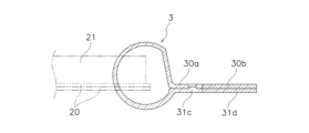
- First embodiment- 1 shows a ring notebook 1 manufactured using a ring threading device according to a first embodiment of the present invention.
- This ring notebook 1 has a plurality of sheets of paper (hereinafter, sometimes simply referred to as "paper") 2 and rings 3.
- the paper 2 has a pair of covers 20 (front and back covers) and a plurality of inner pages 21 stacked between the pair of covers 20.
- the pair of covers 20 are formed larger than the inner pages 21 (see Figs. 8 and 9).
- a plurality of binding holes 21a are formed at a predetermined pitch at the end of the paper 2.
- Figures 2 to 4 show the rings 3 used in the ring notebook 1 of this embodiment.
- the rings 3 shown in Figures 2 to 4 are not the rings 3 in the completed ring notebook 1, but ring materials.
- the rings 3 shown in these figures are in a state before they are inserted into the binding holes 21a of the papers 2 to bind the papers.
- Figure 3 is an enlarged partial view of Figure 2
- Figure 4 is a cross-sectional view of the ring 3.
- the ring 3 is made of synthetic resin.
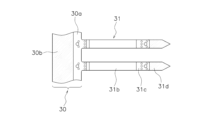
- the ring 3 has a base portion 30 and multiple ring bodies 31, and the base portion 30 and the multiple ring bodies 31 are integrally injection molded.
- the base portion 30 extends in the direction in which the binding holes 21a of the paper 2 are arranged.
- the multiple ring bodies 31 are formed and arranged at the same pitch as the multiple binding holes 21a.
- the ring bodies 31 also extend from the base portion 30 in a direction perpendicular to the direction in which the base portion 30 extends, and have a predetermined length. In the manufacturing process, each ring body 31 is inserted into the corresponding binding hole 21a and formed into a ring shape, and its tip is welded to the base portion 30.
- the base portion 30 of the ring 3 has a welding portion 30a and a cutting portion 30b.
- the welding portion 30a is an area formed on the ring body 31 side of the base portion 30.
- the welding portion 30a is a portion to which the tip of the ring body 31 is welded. More specifically, the tip of the ring body 31, which is inserted into the binding hole 21a of the paper 2 and curved into a ring shape, is welded to the welding portion 30a.
- the cutting portion 30b is an area (indicated by multiple dots in Figs. 2 and 3) formed on the end of the base portion 30 on the opposite side to the ring body 31, and is a portion to be cut after the tip of the ring body 31 is welded.
- the ring body 31 has a straight portion 31a, a curved portion 31b, a welded portion 31c, and a cut portion 31d.
- the straight portion 31a extends in a direction substantially perpendicular to the base portion 30.
- the curved portion 31b is curved so as to bulge outward (away from the base portion 30) from the end of the straight portion 31a.
- the welded portion 31c extends from the end of the curved portion 31b substantially parallel to the base portion 30.
- the cut portion 31d is a region that continues to extend from the welded portion 31c, and is a portion that is cut after being welded to the base portion 30.
- the tip of the cut portion 31d is tapered.
- the ring body 31 has a specified area 31e (indicated by multiple dots in FIG. 6) at the tip made of polypropylene resin, and the other area (including the base portion 30) 31f made of polyethylene resin, which are formed by two-color molding.
- the specified area 31e at the tip of the ring body 31 is harder than the other portion 31f, and is less likely to deform.
- the range of the specified area 31e at the tip is set to be approximately the same as or shorter than the cutting portion 31d.
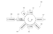
- FIG. 5 shows an overall schematic diagram of a ring notebook manufacturing device 40.
- a notebook supply station 41 a waiting station 42, a ring threading/ring curving station 43, a paper positioning station 44, a ring welding station 45, a ring scrap cutting station 46, and a finished product discharge station 47 are arranged in the above order on a circumference.
- the paper 2 on which the binding hole 21a has been formed by another device is supplied.
- the waiting station 42 a space is reserved for use when replacing parts, etc.
- the ring threading/ring bending station 43 the ring body 31 of the ring 3 is inserted into the binding hole 21a of the paper 2, and the ring body 31 is bent into a ring shape.
- the paper positioning station 44 the position of the paper in the ring welding process is adjusted.
- the welding part 31c and the cut part 31d of the ring body 31 are welded to the welding part 30a and the cut part 30b of the base part 30.
- the ring scrap cutting station 46 the welded base part 30 and the cut parts 30b and 31d of the ring body 31 are cut.
- the finished product discharge station 47 the ring notebook manufactured by the above process is discharged.
- the jig that holds the paper in the note supply station 41 can be rotated while still holding the paper, allowing processing at each step to be carried out. Therefore, there is no need to prepare a jig to hold the paper at each step. In addition, there is no need for a mechanism to transfer the paper between the jigs.
- [Ring threading device] 6 shows the ring threading device 11 provided in the ring threading/ring curving/deforming station 43.
- the ring threading device 11 is a device for threading the ring body 31 of the ring 3 through the binding hole 21a of the paper-sheet 2.
- This ring threading device 11 has a mounting table 51 on which the paper-sheet 2 is placed, a positioning jig 52, and a ring moving mechanism 53.
- this ring threading device 11 passes only the ring body 31 through the binding hole 21a. In other words, the positioning jig 52 is not inserted into the binding hole 21a.
- a jig that holds the upper part of the base portion 30 of the ring 3 is provided above the ring threading device 11. This jig holds the ring 3 supplied from the ring supply device 48.
- the positioning jig 52 is a jig for maintaining the plurality of ring bodies 31 at a predetermined pitch and for holding the plurality of ring bodies 31 in a state in which the predetermined pitch is maintained.
- the positioning jig 52 has a guide roller 521 and multiple nip rollers 522.
- the guide roller 521 extends in the direction in which the binding holes 21a of the paper 2 are arranged. Both ends of the guide roller 521 are rotatably supported by the upper support member 523 shown in FIG. 7, and can rotate clockwise in FIG. 6.
- a guide groove 521a is formed on the surface of the guide roller 521, which has approximately the same width and thickness (depth) as the ring body 31 so that the ring body 31 can fit into it.
- the multiple nip rollers 522 are arranged opposite the guide roller 521 (specifically, the guide groove 521a). Each nip roller 522 is rotatable and connected to each other. In addition, the nip roller 522 is rotatably supported by the upper support member 523 while maintaining a predetermined distance from the guide roller 521, as shown in FIG. 7.
- the positional relationship between the guide roller 521 and the nip roller 522 varies depending on the dimensional relationship between the guide groove 521a and the ring body 31. That is, as shown in FIG. 7, when the surface of the ring body 31 fitted into the guide groove 521a protrudes from the surface of the guide roller 521, the surface of the nip roller 522 contacts the surface of the ring body 31, but does not contact the surface of the guide roller 521. On the other hand, when the surface of the ring body 31 fitted into the guide groove 521a does not protrude from the surface of the guide roller 521, the surface of the nip roller 522 is positioned so as to contact the surface of the guide roller 521.
- the nip roller 522 may be a single roller, similar to the guide roller 521.
- the nip roller 522 rotates in response to the rotation of the guide roller 521.
- the ring moving mechanism 53 has a motor 531 as shown in Fig. 6.
- the motor 531 is provided at the end of the guide roller 521, and rotates the guide roller 521 clockwise in Fig. 6. This allows the multiple ring bodies 31, which are fitted into the guide grooves 521a of the guide roller 521 and maintained at a predetermined pitch, to be inserted into the binding holes 21a while maintaining that state.
- FIG. 7 shows a schematic representation of a ring body, and the actual shape, dimensions, etc. may differ.
- a pair of retraction rollers 60 are provided at a position corresponding to the binding hole 21a below the placement table (not shown in FIG. 7) on which the paper 2 is placed.
- the pair of retraction rollers 60 are each rotatably supported by a lower support member 61 and are connected to each other at a predetermined distance.
- the pair of retraction rollers 60 clamp the tip of the ring body 31 that has passed through the binding hole 21a, and retract the ring body 31 further downward.
- a drive mechanism is provided for rotating the upper support member 523 in the direction of arrow A in the figure and the lower support member 61 in the direction of arrow B.
- the above-described device allows the base portion 30 of the ring 3 and the ring body 31 that has passed through the binding hole 21a of the paper 2 to be curved and deformed into a ring shape, and allows the base portion 30 of the ring 3 and the tip portion of the ring body 31 to be tightly attached to each other.
- a binding hole 20a is formed in the paper 2 by a device other than the manufacturing device 40 shown in Fig. 5.
- rings 3 as shown in Fig. 2 are stacked and supplied to a ring supply device 48.
- the paper 2 with the binding hole 21a formed therein is supplied to the note supply station 41 in a state in which the inner paper 21 is placed on top of a pair of covers 20 arranged below, as shown in Fig. 8.
- a large-sized cover 20 is arranged below, and a small-sized inner paper 21 is stacked on top of it, so that any misalignment between the cover 20 and the inner paper 21 can be confirmed.
- the paper 2 supplied in the above manner is held by a jig (not shown) and transported sequentially in a counterclockwise direction.
- the ring threading/ring bending station 43 receives the paper 2 transported from the standby station 42, and the ring supply device 48 supplies the ring 3.
- the ring threading device 11 shown in FIG. 6 inserts the ring body 31 from above into the binding hole 21a of the paper 2, and the ring bending device bends the base 30 and the ring body 31 into a ring shape.
- each ring body 31 is fitted into the guide groove 521a of the guide roller 521, and is held by the nip roller 522 while maintaining the distance between adjacent ring bodies 31. Then, the guide roller 521 is rotated by the motor 531, causing the tip of the ring body 31 to pass through the binding hole 21a. The tip of the ring body 31 that has passed through the binding hole 21a is clamped by a pair of retraction rollers 60 and moves further downward.
- the upper support member 523 above the mounting table is rotated in the direction of arrow A in the figure, and the lower support member 61 below the mounting table is rotated in the direction of arrow B.
- the jig that grips the base portion 30 of the ring 3 (not shown) is also rotated in the same way. This brings the welded portion 30a and the cut portion 30b of the base portion 30 into close contact with the welded portion 31c and the cut portion 31d of the ring body 31.
- the position of the paper 2 may shift. If the welding process is performed at the next ring welding station 45 while the paper 2 is still out of position, the paper 2 may get in the way of the ring welding process. Therefore, at the paper positioning station 44, the positions of the paper 2 and the ring 3 are adjusted so that the paper 2 does not get in the way of the ring welding process.
- the base portion 30 and the ring body 31 are welded together using a conventionally known ultrasonic welding mechanism or the like.
- the base portion 30 and the cut portions 30b, 31d of the ring body 31 are separated at the ring scrap cutting station 46, and the ring notebook 1 is completed.
- the completed ring notebook 1 has one cover 20 and inner pages 21 moved above the base 30, and the other cover 20 moved below the welded part 31c of the ring body 31.
- each of the multiple ring bodies 31 is positioned by the positioning jig 52, and is inserted into the binding hole 21a while maintaining that position. This allows each ring body 31 to be accurately inserted into and passed through the binding hole 21a. Also, in this embodiment, the positioning jig 52 is not inserted into the binding hole 21a, and only the ring body 31 is inserted. Therefore, there are no restrictions on the size of the positioning jig 52, which allows for greater freedom in design and makes manufacturing easier.
- -Second embodiment- 10 shows a ring threading device 12 according to a second embodiment of the present invention.
- This ring threading device 12 differs from the first embodiment in the positioning jig and the mechanism for driving it, but the other structure, basic operation, and manufacturing method are the same as those of the first embodiment.
- the ring threading device 12 has a mounting table 65 on which the paper is placed, a positioning jig 66, a jig moving mechanism 67, and a ring moving mechanism 68.
- a jig for gripping the upper part of the ring is provided above the ring threading device 12. This jig descends in synchronization with the positioning jig 66.
- the ring used in this second embodiment is formed by two-color molding, as in the first embodiment. That is, a predetermined area 31e at the tip (indicated by multiple dots in FIG. 10) is formed using polypropylene resin, and the other areas (including the base portion 30) 31f are formed using polyethylene resin. For this reason, the predetermined area 31e at the tip of the ring body 31 is harder than the other parts 31f, and is less likely to deform.
- the range of the specified area 31e at the tip is set to be the same as or slightly shorter than the cutting portion 31d, as in the first embodiment.
- This ring threading device 12 passes only the ring body 31 through the binding hole 21a, and the positioning jig 66 is not inserted into the binding hole 21a.
- the positioning jig 66 is placed on the same side as the ring 3, i.e., above the mounting table 65.
- the positioning jig 66 has a main bar 661 and a clamp bar 662.
- the main body bar 661 extends in the direction in which the binding holes 21a of the paper are arranged, and can be raised and lowered freely.
- a guide groove 661a is formed on the surface of the main body bar 661, with approximately the same width and thickness (depth) as the ring body 31, so that the ring body 31 can fit into it. Both longitudinal ends of the main body bar 661 are supported by support members 664 so that they cannot move.
- the clamp bar 662 is disposed opposite the main bar 661 and extends in the same direction as the main bar 661.
- the clamp bar 662 is supported by the support member 664 so that it cannot move in the vertical direction, but can move freely in the horizontal direction.
- the jig moving mechanism 67 has a hydraulic cylinder, etc. This jig moving mechanism 67 allows the clamp bar 662 to move toward and away from the main bar 661.
- the ring movement mechanism 68 has a hydraulic cylinder, etc. This ring movement mechanism 68 can move the support member 664 and raise and lower the main bar 661 and clamp bar 662 in sync.
- each of the ring bodies 31 is fitted into the guide groove 661a of the main body bar 661, and is held by the clamp bar 662 while maintaining the interval between adjacent ring bodies 31. Then, while holding the ring bodies 31, the main body bar 661 and the clamp bar 662 are lowered by the ring moving mechanism 68, and the tip of the ring body 31 is passed through the binding hole 21a. The tip of the ring body 31 that has passed through the binding hole 21a is clamped by a pair of pull-in rollers 60 similar to the first embodiment, and moves further downward.
- the same operation as in the first embodiment is performed, that is, the base portion 30 of the ring 3 above the mounting table is rotated in the direction of arrow A in the figure, and the tip portion of the ring body 31 below the mounting table is rotated in the direction of arrow B.
- This causes the ring 3 to bend and deform, and the welded portion 30a and the cut portion 30b of the base portion 30 come into close contact with the welded portion 31c and the cut portion 31d of the ring body 31.
- the main body bar 661 and the clamp bar 662 may be provided with extensions that extend downward along each ring body 31.
- the ring body 1 and the positioning jig 66 (main body bar 661 and clamp bar 662) are fixed, and the mounting table 65 on which the paper 2 is placed is raised so that the ring body 31 and the extensions of the main body bar 661 and clamp bar 662 pass through the binding hole 21a.
- a hole or notch may be formed in the portion of the ring body 31 that is to be clamped, and a protrusion that fits into the hole or notch may be formed on the clamp bar 662, so that the ring body 31 is held by the clamp bar 662 and the body bar 661.
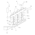
- FIG. 12 shows a ring threading device 13 according to a third embodiment of the present invention.
- the ring 3 is used as in the first embodiment.
- the ring threading device 13 has a mounting table 70 on which the paper is placed, a positioning jig 71, a jig moving mechanism 72, and a ring moving mechanism 73.
- the ring threading device 13 passes not only the ring body 31 but also the positioning jig 71 together with the ring body 31 through the binding hole 21a.
- the positioning jig 71 is placed on the opposite side of the mounting table 70 from the side on which the ring 3 is placed. Specifically, in FIG. 12, the ring 3 is supplied above the mounting table 70, and the positioning jig 71 is placed below the mounting table 70. As in each of the above-mentioned embodiments, the upper part of the ring 3 is held by a jig (not shown). This jig descends in synchronization with the positioning jig 71.
- the positioning jig 71 has a plurality of first and second holders 711 and 712, which are a pair of holders provided to correspond to each of the plurality of ring bodies 31, i.e., to correspond to the binding holes 21a of the paper. Note that in FIG. 12, only one pair of holders (the first and second holders 711 and 712) is shown, and the others are omitted.
- the first holder 711 and the second holder 712 are shaped so that they can move up and down freely and pass through the binding holes 21a of the paper.
- the lower ends of the first holders 711 are connected by connecting parts 711a.
- the lower ends of the second holders 712 are connected by connecting parts 712a.
- the first holder 711 is a plate that is long in the vertical direction, and both longitudinal ends of the connecting portion 711a are supported by the support member 714 so as to be immovable.
- the second holder 712 is a plate that is long in the vertical direction like the first holder 711, and is disposed opposite the first holder 711.
- the tip of the second holder 712 has a bent portion 712b that faces the first holder 711.
- the second holder 712 is supported by the support member 714 so that both longitudinal ends of the connecting portion 712a are immovable in the vertical direction, but are freely movable in the horizontal direction.
- the jig moving mechanism 72 has a hydraulic cylinder or the like. This jig moving mechanism 72 allows the second holder 712 to move toward and away from the first holder 711.
- the second holder 712 may have a connecting portion 712a rotatably connected to the support member 714 or the connecting portion 711a of the first holder 711. In this case, by rotating the second holder 712, the bent portion 712b at the tip can be moved toward or away from the first holder 711.
- the ring movement mechanism 73 has a hydraulic cylinder or the like. This ring movement mechanism 73 can raise and lower the first holder 711 and the second holder 712 supported by the support member 714 together with the support member 714.
- the jig movement mechanism 72 is driven to bring the second holder 712 closer to the first holder 711, and the tip of the ring body 31 is clamped between the holders 711 and 712.
- the jig movement mechanism 72 is driven to bring the second holder 712 closer to the first holder 711, and the tip of the ring body 31 is clamped between the holders 711 and 712.
- each of the multiple ring bodies 31 is clamped between the holders 711 and 712, and the spacing between adjacent ring bodies 31 is maintained and the ring bodies 31 are positioned.
- the ring moving mechanism 73 is driven to lower both holders 711 and 712 holding the ring body 31 in this state, and both the ring body 31 and both holders 711 and 712 pass through the binding hole 21a.
- the jig that grips the upper part of the ring 3 also descends in synchronization.
- the ring 3 and both holders 711, 712 may be fixed, and the placement table 51 on which the paper 2 is placed may be raised to pass both the ring body 31 and both holders 711, 712 through the binding hole 21a.
- a jig (not shown) that grips the upper part of the ring 3 is rotated in one direction, while both holders 711, 712 are rotated in the other direction. Then, the welded portion 30a and the cut portion 30b of the base portion 30 of the ring 3 are brought into close contact with the welded portion 31c and the cut portion 31d of the ring body 31. Subsequent processing is the same as in the first embodiment.
- each of the multiple ring bodies 31 can be positioned and inserted into the binding hole 21a while maintaining that position. Therefore, each ring body 31 can be accurately inserted into and passed through the binding hole 21a.
- both holders 711, 712 pass through the binding hole 21a together with the ring body 31 while gripping the ring body 31. This allows the ring body 31 to pass through the binding hole 21a with high precision and reliability.
- the configuration in which the pair of holders hold the ring body 31 is not limited to the configuration shown in FIG. 12 in which the ring body 31 is clamped.
- a hole or notch may be formed in the tip of the ring body 31, and the bent portion 712b of the second holder 712 may be inserted into the hole or notch so that the tip of the bent portion 712b comes into contact with the first holder 711, thereby holding the ring body 31 in a hooked manner.
- FIG. 13 shows a ring threading device 14 according to a fourth embodiment of the present invention.
- This ring threading device 14 has a mounting table 75 on which the paper is placed, a positioning jig 76, a back plate 77, a jig moving mechanism 78, and a ring moving mechanism 79.
- this ring threading device 14 passes not only the ring body, but also the positioning jig 76 together with the ring body through the binding hole 21a.
- This ring threading device 14 uses a ring 8 as shown in FIG. 13. That is, the ring 8 has a base portion 80 and a ring body 81. A protrusion 81a that protrudes from the surface by a predetermined thickness is integrally formed at the tip of the ring body 81. The lower end of the protrusion 81a has a tapered shape like the tip of the ring body 81. In addition, the upper end of the protrusion 81a has a tapered shape that tapers upward.
- the positioning jig 76 is disposed above the mounting table 75, i.e., on the same side of the mounting table 75 as the side on which the ring 8 is disposed, and can be raised and lowered freely.
- the positioning jig 76 is, for example, a metal plate, and has multiple positioning portions 761 and connecting portions 762.
- Each positioning portion 761 is formed to correspond to the respective binding hole 21a of the ring body 81, i.e., the paper 2, and has a shape that allows it to pass through the binding hole 21a of the paper.
- a recess 761a is formed at the tip of the positioning portion 761.
- the recess 761a has a shape that tapers upward, and can engage with the upper end of the protrusion 81a formed at the tip of the ring body 81.
- the connecting portion 762 is formed to extend in the same direction as the base portion 80 of the ring 8. This connecting portion 762 connects the upper ends of the multiple positioning portions 761. Both longitudinal ends of the connecting portion 762 are supported by the support member 763 so that it cannot move up and down, but can move freely in the horizontal direction.
- the backplate 77 is positioned opposite the positioning jig 76. In other words, the backplate 77 is positioned so that it comes into contact with the surface of the ring body 81 opposite the surface that comes into contact with the positioning jig 86. This backplate 77 stabilizes the position of the ring 8 as it descends.
- the jig moving mechanism 78 has a hydraulic cylinder or the like. This jig moving mechanism 78 makes it possible to move the positioning jig 76 closer to and away from the back plate 77.
- the ring movement mechanism 79 has a hydraulic cylinder, etc. This ring movement mechanism 79 makes it possible to raise and lower the positioning jig 76 supported by the support member 763 together with the support member 763.
- the positioning jig 76 is moved close to the back plate 77 by the jig moving mechanism 78. As a result, the ring body 81 of the ring 8 is sandwiched between the back plate 77 and the positioning jig 76. Next, the positioning jig 76 is lowered by the ring moving mechanism 79. As a result, the recess 761a of the positioning portion 761 engages with the protrusion 81a of the ring body 81. In this state, the positional relationship between the two is fixed by the recess 761a of the positioning portion 761 and the protrusion 81a of the ring body 81, and the adjacent ring bodies 81 are positioned while maintaining the interval between them. Then, when the positioning jig 76 and the ring 8 are lowered from this state, the positioning portion 761 of the positioning jig 76 and the ring body 81 pass through the binding hole 21a.
- the ring 3 and the positioning jig 76 may be fixed, and the platform 75 on which the paper 2 is placed may be raised to pass both the ring body 31 and the positioning jig 76 through the binding hole 21a.
- This fourth embodiment also provides the same effects as the third embodiment.
- -Fifth embodiment- [composition] 14 shows a ring threading device 15 according to a fifth embodiment of the present invention.
- This ring threading device 15 has a mounting table 85 on which the paper is placed, a positioning jig 86, upper and lower back plates 87, a jig moving mechanism 88, and a ring moving mechanism 89.
- this ring threading device 15 passes not only the ring body, but also the positioning jig 86 together with the ring body through the binding hole 21a.
- this ring threading device 15 uses the same ring 8 as in the fourth embodiment.
- the positioning jig 86 is placed on the opposite side of the mounting table 85 from the side on which the ring 8 is placed. Specifically, in FIG. 14, the ring 8 is supplied above the mounting table 85, and the positioning jig 86 is placed below the mounting table 85. The upper part of the ring 8 is held by a jig (not shown). This jig descends in sync with the positioning jig 86.
- the positioning jig 86 is, for example, a metal plate, and has multiple positioning portions 861, engagement portions 862, and connecting portions 863.
- Each positioning portion 861 is formed to correspond to the respective binding hole 21a of the ring body 81, i.e., the paper 2, and has a shape that allows it to pass through the binding hole 21a of the paper.
- the engagement portion 862 is provided on the surface of the tip of the positioning portion 861, on the side facing the back plate 87.
- the engagement portion 862 has a predetermined thickness, and is provided with a recess 862a at the lower end.
- the recess 862a is shaped to taper upward, and is capable of engaging with the upper end of the protrusion 81a of the ring body 81.
- the connecting portion 863 is formed to extend in the same direction as the base portion 80 of the ring 8. This connecting portion 863 connects the lower ends of the multiple positioning portions 861. Both longitudinal ends of the connecting portion 863 are supported by the support member 864 so that it cannot move up and down, but can move freely in the horizontal direction.
- the upper and lower back plates 87 are provided above and below the mounting base 85 at positions laterally spaced from the mounting base 85.
- the back plates 87 are positioned so that they come into contact with the surface of the ring body 81 opposite the side that comes into contact with the positioning jig 86.
- the back plates 87 stabilize the position of the ring 8 as it descends.
- the jig moving mechanism 88 has a hydraulic cylinder, etc. This jig moving mechanism 88 makes it possible to move the positioning jig 86 closer to and away from the back plate 87.
- the ring movement mechanism 89 has a hydraulic cylinder, etc. This ring movement mechanism 89 makes it possible to raise and lower the positioning jig 86 supported by the support member 864 together with the support member 864.
- the positioning jig 86 is raised by the ring movement mechanism 89, and the positioning portion 861 passes through the binding hole 21 a. Then, at the point where the engagement portion 862 of the positioning jig 86 is raised to a height exceeding the protrusion portion 81 a of the ring main body 81, the movement of the positioning jig 86 is stopped.
- the positioning jig 86 is brought close to the upper back plate 87 by the jig movement mechanism 88, and the tip of the ring body 81 is clamped between the positioning jig 86 and the back plate 87.
- the positioning jig 86 is lowered in this state by the ring movement mechanism 89, the recess 862a of the engagement portion 862 engages with the protrusion 81a of the ring body 81.
- the spacing between the multiple ring bodies 81 is maintained and positioned by the positioning jig 86.
- the ring body 81 which has been positioned by the positioning jig 86, is lowered together with the positioning jig 86 by the ring moving mechanism 89, and passes through the binding hole 21a. At this time, the jig that grips the upper part of the ring 8 also descends in synchronization.
- the ring 3 and the positioning jig 86 can be fixed, and the platform 85 on which the paper 2 is placed can be raised to pass both the ring body 31 and the positioning jig 86 through the binding hole 21a.
- This type of ring threading device 15 can also provide the same effects as the third and fourth embodiments.
- a specific area at the tip of the ring body is formed by two-color molding to give it a higher hardness than the other parts, but it is also possible to make the specific area have the same hardness as the other parts without two-color molding.
- the ring body is made to pass through the binding holes from above, but this is not limited to this, and the ring body may be made to pass through the binding holes from below, or further, the binding holes may be arranged to open horizontally, and the ring body may be made to pass through the binding holes horizontally.
- the shape, etc. of the positioning jig is not limited to those of the above-described embodiments, but may be any configuration that can position each of the multiple ring bodies and maintain that state.
Landscapes
- Engineering & Computer Science (AREA)
- Textile Engineering (AREA)
- Sheet Holders (AREA)
- Folding Of Thin Sheet-Like Materials, Special Discharging Devices, And Others (AREA)
Priority Applications (4)
| Application Number | Priority Date | Filing Date | Title |
|---|---|---|---|
| JP2024558519A JPWO2024105758A1 (https=) | 2022-11-15 | 2022-11-15 | |
| CN202280100361.6A CN119923322A (zh) | 2022-11-15 | 2022-11-15 | 环圈穿过装置及环圈装订本的制造方法 |
| US18/995,097 US20260014812A1 (en) | 2022-11-15 | 2022-11-15 | Ring threading device and method for manufacturing ring notebook |
| PCT/JP2022/042319 WO2024105758A1 (ja) | 2022-11-15 | 2022-11-15 | リング通し装置及びリングノートの製造方法 |
Applications Claiming Priority (1)
| Application Number | Priority Date | Filing Date | Title |
|---|---|---|---|
| PCT/JP2022/042319 WO2024105758A1 (ja) | 2022-11-15 | 2022-11-15 | リング通し装置及びリングノートの製造方法 |
Publications (1)
| Publication Number | Publication Date |
|---|---|
| WO2024105758A1 true WO2024105758A1 (ja) | 2024-05-23 |
Family
ID=91084002
Family Applications (1)
| Application Number | Title | Priority Date | Filing Date |
|---|---|---|---|
| PCT/JP2022/042319 Ceased WO2024105758A1 (ja) | 2022-11-15 | 2022-11-15 | リング通し装置及びリングノートの製造方法 |
Country Status (4)
| Country | Link |
|---|---|
| US (1) | US20260014812A1 (https=) |
| JP (1) | JPWO2024105758A1 (https=) |
| CN (1) | CN119923322A (https=) |
| WO (1) | WO2024105758A1 (https=) |
Citations (3)
| Publication number | Priority date | Publication date | Assignee | Title |
|---|---|---|---|---|
| US2206394A (en) * | 1938-10-17 | 1940-07-02 | Frank F Farkas | Leaf binding device |
| US5464312A (en) * | 1994-05-10 | 1995-11-07 | General Binding Corporation | Automatic binder |
| JP2015174413A (ja) * | 2014-03-18 | 2015-10-05 | コクヨS&T株式会社 | リングノート、リングノートの製造方法 |
Family Cites Families (7)
| Publication number | Priority date | Publication date | Assignee | Title |
|---|---|---|---|---|
| US2273824A (en) * | 1939-12-19 | 1942-02-24 | Plastic Binding Corp | Apparatus and method of making plastic binders |
| US2930054A (en) * | 1957-09-12 | 1960-03-29 | Gen Binding Corp | Method and apparatus for binding books and forming plastic binding elements therefor |
| JP4956508B2 (ja) * | 2008-08-18 | 2012-06-20 | 渡辺通商株式会社 | 紙製綴じ具を用いた冊子の製造装置 |
| JP5097099B2 (ja) * | 2008-12-15 | 2012-12-12 | 渡辺通商株式会社 | 紙製綴じ具を用いた冊子の製造装置 |
| JP5374721B2 (ja) * | 2010-04-12 | 2013-12-25 | コクヨ株式会社 | ノート |
| JP5614149B2 (ja) * | 2010-07-29 | 2014-10-29 | コニカミノルタ株式会社 | 画像形成システム |
| JP2014200927A (ja) * | 2013-04-01 | 2014-10-27 | コニカミノルタ株式会社 | 押圧部材および製本装置 |
-
2022
- 2022-11-15 JP JP2024558519A patent/JPWO2024105758A1/ja active Pending
- 2022-11-15 US US18/995,097 patent/US20260014812A1/en active Pending
- 2022-11-15 WO PCT/JP2022/042319 patent/WO2024105758A1/ja not_active Ceased
- 2022-11-15 CN CN202280100361.6A patent/CN119923322A/zh active Pending
Patent Citations (3)
| Publication number | Priority date | Publication date | Assignee | Title |
|---|---|---|---|---|
| US2206394A (en) * | 1938-10-17 | 1940-07-02 | Frank F Farkas | Leaf binding device |
| US5464312A (en) * | 1994-05-10 | 1995-11-07 | General Binding Corporation | Automatic binder |
| JP2015174413A (ja) * | 2014-03-18 | 2015-10-05 | コクヨS&T株式会社 | リングノート、リングノートの製造方法 |
Also Published As
| Publication number | Publication date |
|---|---|
| US20260014812A1 (en) | 2026-01-15 |
| CN119923322A (zh) | 2025-05-02 |
| JPWO2024105758A1 (https=) | 2024-05-23 |
Similar Documents
| Publication | Publication Date | Title |
|---|---|---|
| US7325799B2 (en) | Method and apparatus for booklet production | |
| EP1568421B1 (en) | Method of processing of a formed product and metal upper mold used for the method | |
| KR20140059223A (ko) | 프레스 성형방법 및 프레스 성형장치 | |
| WO2024105758A1 (ja) | リング通し装置及びリングノートの製造方法 | |
| EP1462190B1 (en) | Method and apparatus for incremental forming | |
| JP2011031515A (ja) | 罫入れ装置および罫入れ装置におけるカウンタプレート | |
| CN203622932U (zh) | 绝缘用薄膜成型机 | |
| JP4635767B2 (ja) | バインダー | |
| JP4635768B2 (ja) | バインダー | |
| KR20000005843A (ko) | 플랜지베어링제조방법및장치 | |
| CN102029326A (zh) | 折床模具固定结构 | |
| CN208374002U (zh) | 一种用于折弯工件的模具 | |
| JP2008178916A (ja) | プレス加工装置 | |
| KR20170111587A (ko) | 공작기계 | |
| CN216655927U (zh) | 一种新型的折弯结构 | |
| JP7663402B2 (ja) | 樹脂成形品の射出成形方法及び射出成形金型 | |
| JP4906387B2 (ja) | 金属フィルム成形装置及びptpシートの製造装置 | |
| CN105436295B (zh) | 一种连续模 | |
| TW202235183A (zh) | 工具夾持組件及組件 | |
| JP4951215B2 (ja) | メタルハニカム触媒担体の組立て方法及びその装置 | |
| RS66217B1 (sr) | Postupak za proizvodnju komponente nosača kablova i presa za žljebljenje za proizvodnju takve komponente nosača kablova | |
| JP2002336998A (ja) | プレス機械用順送り金型 | |
| KR100343415B1 (ko) | 원터치타입의 벤딩노즐을 구비한 컷팅블레이드의 절곡장치 | |
| JP2006231390A (ja) | 環状ワーク整列装置及び線材成形機 | |
| US20060052007A1 (en) | Apparatus for inserting single spring |
Legal Events
| Date | Code | Title | Description |
|---|---|---|---|
| 121 | Ep: the epo has been informed by wipo that ep was designated in this application |
Ref document number: 22965734 Country of ref document: EP Kind code of ref document: A1 |
|
| WWE | Wipo information: entry into national phase |
Ref document number: 2024558519 Country of ref document: JP |
|
| WWE | Wipo information: entry into national phase |
Ref document number: 18995097 Country of ref document: US |
|
| WWE | Wipo information: entry into national phase |
Ref document number: 202517013526 Country of ref document: IN |
|
| WWP | Wipo information: published in national office |
Ref document number: 202517013526 Country of ref document: IN |
|
| WWE | Wipo information: entry into national phase |
Ref document number: 202280100361.6 Country of ref document: CN |
|
| WWP | Wipo information: published in national office |
Ref document number: 202280100361.6 Country of ref document: CN |
|
| NENP | Non-entry into the national phase |
Ref country code: DE |
|
| 122 | Ep: pct application non-entry in european phase |
Ref document number: 22965734 Country of ref document: EP Kind code of ref document: A1 |
|
| WWP | Wipo information: published in national office |
Ref document number: 18995097 Country of ref document: US |