WO2024101005A1 - 静電式座標入力装置、及び、静電式座標入力装置における操作判定方法 - Google Patents
静電式座標入力装置、及び、静電式座標入力装置における操作判定方法 Download PDFInfo
- Publication number
- WO2024101005A1 WO2024101005A1 PCT/JP2023/034156 JP2023034156W WO2024101005A1 WO 2024101005 A1 WO2024101005 A1 WO 2024101005A1 JP 2023034156 W JP2023034156 W JP 2023034156W WO 2024101005 A1 WO2024101005 A1 WO 2024101005A1
- Authority
- WO
- WIPO (PCT)
- Prior art keywords
- pointing
- state
- threshold
- electrostatic
- determination
- Prior art date
- Legal status (The legal status is an assumption and is not a legal conclusion. Google has not performed a legal analysis and makes no representation as to the accuracy of the status listed.)
- Ceased
Links
Images














Classifications
-
- G—PHYSICS
- G06—COMPUTING OR CALCULATING; COUNTING
- G06F—ELECTRIC DIGITAL DATA PROCESSING
- G06F3/00—Input arrangements for transferring data to be processed into a form capable of being handled by the computer; Output arrangements for transferring data from processing unit to output unit, e.g. interface arrangements
- G06F3/01—Input arrangements or combined input and output arrangements for interaction between user and computer
- G06F3/03—Arrangements for converting the position or the displacement of a member into a coded form
- G06F3/041—Digitisers, e.g. for touch screens or touch pads, characterised by the transducing means
- G06F3/044—Digitisers, e.g. for touch screens or touch pads, characterised by the transducing means by capacitive means
- G06F3/0446—Digitisers, e.g. for touch screens or touch pads, characterised by the transducing means by capacitive means using a grid-like structure of electrodes in at least two directions, e.g. using row and column electrodes
-
- G—PHYSICS
- G06—COMPUTING OR CALCULATING; COUNTING
- G06F—ELECTRIC DIGITAL DATA PROCESSING
- G06F2203/00—Indexing scheme relating to G06F3/00 - G06F3/048
- G06F2203/041—Indexing scheme relating to G06F3/041 - G06F3/045
- G06F2203/04108—Touchless 2D- digitiser, i.e. digitiser detecting the X/Y position of the input means, finger or stylus, also when it does not touch, but is proximate to the digitiser's interaction surface without distance measurement in the Z direction
Definitions
- This disclosure relates to an electrostatic coordinate input device and an operation determination method for an electrostatic coordinate input device.
- a sensor controller connected to a matrix electrode including M first electrodes extending in a first direction and N second electrodes extending in a second direction.
- the sensor controller executes a finger touch detection step of supplying a predetermined signal to the M first electrodes and detecting a finger touch area indicating an area touched by a finger based on a predetermined signal detected by the N second electrodes, and a full range scan step of detecting an undetected stylus and deriving the position coordinates of the stylus using at least a part of the M first electrodes and at least a part of the N second electrodes.
- the sensor controller also executes a sector scan step of deriving the position coordinates of an already detected stylus using a number of the first electrodes less than the number of the first electrodes used in the full range scan step and a number of the second electrodes less than the number of the second electrodes used in the full range scan step, a determination step of determining whether the position coordinates derived in the sector scan step are included in any of the finger touch areas detected in the finger touch detection step, and an invalidation step of invalidating the position coordinates determined to be included in the determination step.
- the sensor controller further includes a palm rejection step in which the one or more finger touch areas detected in the finger touch detection step are invalidated by a palm rejection process based on the size of the area.
- the sensor controller performs a process for determining whether the position coordinates derived in the sector scan step are included in any of the finger touch areas detected in the finger touch detection step before executing the palm rejection step (see, for example, Patent Document 1).
- the objective of the present invention is to provide an electrostatic coordinate input device that can accurately determine the presence or absence of operations such as contact or proximity depending on the distance between the indicator and the device, and can prevent erroneous operations, and a method for determining operation in an electrostatic coordinate input device.
- the electrostatic coordinate input device of the embodiment of the present disclosure includes an operation surface, a plurality of sensor electrodes arranged on the rear side of the operation surface, a measurement circuit that measures the capacitance of each of the plurality of sensor electrodes, and a calculation unit that calculates the position of a pointer based on the plurality of capacitances measured by the measurement circuit, the calculation unit calculates the maximum capacitance between the pointer and the sensor electrodes based on the plurality of capacitances, and sets a non-pointing judgment threshold used to judge a non-pointing operation of the pointer that is not a pointing operation based on the maximum capacitance, and judges that the operation of the pointer is the non-pointing operation when the number of capacitances among the plurality of capacitances that exceed the non-pointing judgment threshold exceeds a judgment number threshold.
- an electrostatic coordinate input device and an operation determination method for an electrostatic coordinate input device that can determine with high accuracy whether an operation such as contact or proximity has occurred based on the distance between the indicator and the device, and can prevent erroneous operations.
- FIG. 11 is a diagram illustrating an example of a threshold value for determining a distance state.
- FIG. 11 is a diagram showing distance states determined by the electrostatic coordinate input device according to the embodiment in relation to a maximum capacitance and a previous distance state.
- FIG. FIG. 4 is a flowchart showing a process executed by a control device of the electrostatic coordinate input device according to the embodiment.
- 13 is a flowchart illustrating an example of a distance state determination process. 13 is a diagram showing an example of table data of threshold values used in the non-pointing operation determination process.
- FIG. 13 is a flowchart showing a non-pointing operation determination process.
- 5 is a diagram illustrating an example of a distribution of electrostatic capacitance detected by the electrostatic sensor;
- FIG. 5 is a diagram illustrating an example of a distribution of electrostatic capacitance detected by the electrostatic sensor;
- FIG. 5 is a diagram illustrating an example of a distribution of electrostatic capacitance detected by the electrostatic sensor;
- FIG. 5 is a diagram illustrating an example of a distribution of electrostatic capacitance detected by the electro
- FIG. 4 is a diagram illustrating an example of a distribution of electrostatic capacitance detected by an electrostatic sensor
- FIG. 5 is a diagram illustrating an example of a distribution of electrostatic capacitance detected by the electrostatic sensor
- FIG. 1A to 1C are diagrams illustrating an example of the operation of the electrostatic coordinate input device according to the embodiment.
- 1A to 1C are diagrams illustrating an example of the operation of the electrostatic coordinate input device according to the embodiment.
- 1A to 1C are diagrams illustrating an example of the operation of the electrostatic coordinate input device according to the embodiment.
- 1A to 1C are diagrams illustrating an example of the operation of the electrostatic coordinate input device according to the embodiment.
- 1A to 1C are diagrams illustrating an example of the operation of the electrostatic coordinate input device according to the embodiment.
- 1A to 1C are diagrams illustrating an example of the operation of the electrostatic coordinate input device according to the embodiment.
- 1A to 1C are diagrams illustrating an example of the operation of the electrostatic coordinate input device according to the embodiment.
- 1A to 1C are diagrams illustrating an example of the operation of the electrostatic coordinate input device according to the embodiment.
- 1A to 1C are diagrams illustrating an example of the operation of the electrostatic coordinate input device according to the embodiment.
- 1A to 1C are diagrams illustrating an example of the operation of the electrostatic coordinate input device according to the embodiment.
- 1A to 1C are diagrams illustrating an example of the operation of the electrostatic coordinate input device according to the embodiment.
- 13A and 13B are diagrams illustrating modified examples of table data of threshold values used in the non-pointing operation determination process.
- 13A and 13B are diagrams illustrating modified examples of table data of threshold values used in the non-pointing operation determination process.
- 13A and 13B are diagrams illustrating modified examples of table data of threshold values used in the non-pointing operation determination process.
- 13 is a flowchart showing a modified example of the non-pointing operation determination process.
- FIG. 1 and 2 are diagrams showing an example of the configuration of the electrostatic coordinate input device 100 of the embodiment.
- FIG. 1 shows a state in which the electrostatic coordinate input device 100 is in an operating state and the display device 110 is displaying an input image.
- the electrostatic coordinate input device 100 is in an input mode.
- the input mode is a mode in which an operation input to the electrostatic coordinate input device 100 is possible.
- FIG. 2 shows a state in which the electrostatic coordinate input device 100 is in a standby state and the display device 110 is displaying a standby image. When the display device 110 is displaying a standby image, the electrostatic coordinate input device 100 is in a power saving mode.
- FIG. 3 is a diagram showing an example of the configuration of the electrostatic sensor 120 and the control device 130 of the electrostatic coordinate input device 100.
- the display device 110 is an example of a display unit
- the electrostatic sensor 120 is an example of a detection unit
- the control device 130 is an example of a control unit.
- the following description defines the XYZ coordinate system.
- the direction parallel to the X axis (X direction), the direction parallel to the Y axis (Y direction), and the direction parallel to the Z axis (Z direction) are mutually perpendicular.
- the -Z direction is the direction approaching the electrostatic sensor 120
- the +Z direction is the direction away from the electrostatic sensor 120.
- a planar view refers to an XY plane view.
- the length, width, thickness, etc. of each part may be exaggerated to make the configuration easier to understand.
- the electrostatic coordinate input device 100 may be, for example, a tablet-type input device that is placed in a store or facility and used by an unspecified number of users, or the input section of an ATM (Automatic Teller Machine). It may also be the input section of an electrical cooking appliance that needs to be kept clean.
- the electrostatic coordinate input device 100 may also be a tablet computer, smartphone, game console, etc., for personal use.
- the electrostatic coordinate input device 100 includes a housing 101, a top panel 105, a display device 110, an electrostatic sensor 120, and a control device 130. Although the control device 130 (see FIG. 3) is omitted in FIGS. 1 and 2, the control device 130 is provided, for example, below the display device 110 and the electrostatic sensor 120 inside the housing 101.
- the electrostatic coordinate input device 100 includes the electrostatic sensor 120 and the control device 130 shown in FIG. 3.
- the housing 101 is a case made of resin, metal, or the like that houses the display device 110, the electrostatic sensor 120, and the control device 130.
- the display device 110 is disposed below the transparent electrostatic sensor 120, and is visible through an operation surface 105A that is the upper surface of a transparent top panel 105 provided in an opening at the top of the housing 101.
- the electrostatic coordinate input device 100 can be operated in both a state where a pointer such as a user's hand is not in contact with the operation surface 105A, and a state where a pointer such as a user's hand is in contact with the operation surface 105A.
- the proximity operation, selection operation, and confirmation operation are operations performed with a pointer such as a hand not in contact with the operation surface 105A.
- the contact operation is an operation performed with a pointer such as a hand in contact with the operation surface 105A.
- the electrostatic coordinate input device 100 determines five distance states between an indicator such as a hand and the operation surface 105A in order to distinguish between the four operation methods.
- the five distance states are a non-detection state, a proximity state, a selection state, a confirmation state, and a contact state.
- the five distance states include a contact state indicating that an indicator such as a hand is in contact with the operation surface 105A, and multiple non-contact states indicating that an indicator such as a hand is not in contact with the operation surface 105A.
- the non-detection state, proximity state, selection state, and confirmation state are non-contact states.
- the non-detection state is a state in which the proximity operation, selection operation, confirmation operation, and contact operation are not being performed.
- the proximity state, selection state, confirmation state, and contact state are states in which the proximity operation, selection operation, confirmation operation, and contact operation are being performed, respectively.
- the electrostatic coordinate input device 100 uses multiple capacitance thresholds when determining the operation method. As the state changes to the contact state, confirmation state, selection state, proximity state, and non-detection state, the position of the indicator, such as a hand, moves away from the operation surface 105A.
- the electrostatic coordinate input device 100 is an input device that is operated by the user performing a pointing operation.
- a pointing operation is an operation performed by holding a finger substantially perpendicular to the operation surface 105A.
- the number of fingers used in the pointing operation may be multiple, but it is preferable to use one finger.
- the electrostatic coordinate input device 100 determines whether the pointing operation is being performed correctly.
- the electrostatic coordinate input device 100 judges whether the operation by the user is a pointing operation or a non-pointing operation. Then, when a pointing operation is detected a predetermined number of times (three times as an example), the electrostatic coordinate input device 100 judges that a pointing operation is being performed. Also, when a non-pointing operation is detected a predetermined number of times (three times as an example), the electrostatic coordinate input device 100 judges that a non-pointing operation is being performed.
- the proximity operation is an operation of bringing hand H close to operation surface 105A of electrostatic coordinate input device 100 without touching it, and is an operation for switching electrostatic coordinate input device 100 from the standby state shown in FIG. 2 to the operating state shown in FIG. 1.
- the selection operation is an operation in which, after performing the proximity operation, the hand H is brought even closer to the operation surface 105A of the electrostatic coordinate input device 100 without touching it, and a GUI button displayed on the display device 110 is selected.
- the confirmation operation is an operation in which, after a selection operation has been performed, the hand H is brought even closer to the operation surface 105A of the electrostatic coordinate input device 100 without touching it, thereby confirming the operation input for the selected GUI button.
- the confirmation operation is a non-contact operation input, and is a non-contact operation of the electrostatic coordinate input device 100 without touching the operation surface 105A with the hand H. Operation inputs performed by non-contact selection operations and confirmation operations may be referred to as hover inputs or touchless inputs.
- a contact operation is an operation in which, after a selection operation has been performed, hand H is brought even closer to operation surface 105A of electrostatic coordinate input device 100 to touch operation surface 105A, thereby finalizing the operation input for the selected GUI button.
- a contact operation may also be referred to as a touch input.
- the display device 110 is, for example, a liquid crystal display or an organic EL (Electroluminescence) display.
- the display device 110 is a display for realizing a GUI (Graphic User Interface).
- the display device 110 displays an image of a GUI button 111, a cursor, and an image of an input content display section 115 that displays input contents.
- the GUI button 111 is an example of an operation section, and is, for example, arranged in a matrix in a planar view. Also, the GUI button 111 is, for example, a circular shape that imitates a push button.
- Figures 1 to 3 show, as an example, a total of 45 GUI buttons 111, including 26 alphabetical GUI buttons 111, 15 numeric keypad-style GUI buttons 111, and four GUI buttons 111: a menu key (the key with three lines at the top left), a Caps Lock key, a backspace key (top right), and an Enter key (bottom right).
- the 45 GUI buttons 111 are arranged in five rows in the Y direction and 11 rows in the X direction. The rows extend in the X direction, and Y extends in the column direction. Note that the GUI buttons 111 are not limited to alphabetical characters or numeric keypad numbers, but may be letters or symbols of other languages.
- the electrostatic coordinate input device 100 may have an operation unit with alphabets, numbers, symbols, etc. printed on the top panel 105 instead of all or at least a part of the 45 GUI buttons 111.
- a backlight may be provided on the back side of the top panel 105, and the operation unit with the alphabets, numbers, symbols, etc. printed on it may be made transparent. Then, when the electrostatic coordinate input device 100 is in a standby state, the backlight may be turned off, and when the electrostatic coordinate input device 100 is switched to the input mode, the backlight may be turned on so that the alphabets, numbers, symbols, etc. on the operation unit of the top panel 105 are illuminated.
- a liquid crystal display, an organic EL display, etc. may be provided only in the input content display unit 115 to display the input contents.
- the electrostatic sensor 120 is arranged on the display device 110, and has a plurality of sensor electrodes 121X extending in the X direction and a plurality of sensor electrodes 121Y extending in the Y direction, as shown in FIG. 3.
- the sensor electrodes 121X and 121Y are an example of electrodes of a detection unit, and are connected to the control device 130 via wirings 122X and 122Y, respectively.
- a transparent conductive film such as ITO (Indium Tin Oxide) is formed on the surface of transparent glass, and the sensor electrodes 121X and 121Y and wirings 122X and 122Y are patterned.
- the electrostatic capacitance detected by the electrostatic sensor 120 is input to the control device 130.
- the electrostatic capacitance detected by the electrostatic sensor 120 is an example of a detection result of the electrostatic sensor 120.
- FIG. 3 shows, as an example, a plurality of sensor electrodes 121X and a plurality of sensor electrodes 121Y.
- the spacing between the sensor electrodes 121X and the spacing between the sensor electrodes 121Y are narrower than the spacing between the GUI buttons 111.
- the sensor electrodes 121X are scanned row by row, and the sensor electrodes 121Y are scanned column by column.
- the AD conversion unit 132 converts the capacitances at the intersections of the sensor electrodes 121X and the sensor electrodes 121Y into digital values.
- the counter 133 counts the change in the output of the AD conversion unit 132 and outputs the difference value ⁇ AD at each intersection. It is also possible to increase the resolution by using an interpolation method based on the spacing between the sensor electrodes 121X and the spacing between the sensor electrodes 121Y. In this case, the spacing between the sensor electrodes 121X and the spacing between the sensor electrodes 121Y may be wider than the spacing between the GUI buttons 111.
- the GUI buttons 111 may correspond one-to-one to sensor electrodes of approximately the same size as the GUI buttons 111.
- the position of the hand H in the XY coordinate system detected by the electrostatic coordinate input device 100 using the electrostatic sensor 120 is, for example, the XY coordinate system with the largest capacitance in the area where the hand H is present. Furthermore, the position of the hand H in the Z direction detected by the electrostatic coordinate input device 100 using the electrostatic sensor 120 is a value that is inversely proportional to the capacitance detected by the electrostatic sensor 120, so determining the position of the hand H in the Z direction is synonymous with determining the capacitance between the hand H and the electrostatic sensor 120.
- the electrostatic coordinate input device 100 determines the position of the hand H in the Z direction from the capacitance between the hand H and the electrostatic sensor 120, but in the following, when it is easier to understand to explain it as the position of the hand H in the Z direction, it will be explained as the position of the hand H in the Z direction.
- the control device 130 is realized by a computer including a central processing unit (CPU), a random access memory (RAM), a read only memory (ROM), an input/output interface, an internal bus, and the like.
- CPU central processing unit
- RAM random access memory
- ROM read only memory
- input/output interface an internal bus, and the like.
- the control device 130 has a main control unit 131, an AD (Analog to Digital) conversion unit 132, a counter 133, a calculation unit 134, an operation control unit 135, a display control unit 136, and a memory 137.
- the main control unit 131, the AD conversion unit 132, the counter 133, the calculation unit 134, the operation control unit 135, and the display control unit 136 are functional blocks that represent the functions of the programs executed by the control device 130.
- the memory 137 is a functional representation of the memory of the control device 130.
- the main control unit 131 is a processing unit that controls the processing of the control device 130, and executes processes other than those executed by the AD conversion unit 132, the counter 133, the calculation unit 134, the operation control unit 135, and the display control unit 136. For example, the main control unit 131 scans the multiple sensor electrodes 121X and the multiple sensor electrodes 121Y.
- the AD conversion unit 132 converts the output of the electrostatic sensor 120 into a digital value.
- the output of the AD conversion unit 132 is a detection value of the capacitance at each intersection of the sensor electrodes 121X and 121Y of the electrostatic sensor 120.
- the counter 133 counts and outputs the difference value of the output of the AD conversion unit 132 with respect to a reference value.
- the difference value is the count value of the change in the output with respect to the reference value.
- this is referred to as the difference value ⁇ AD.
- the reference value is the capacitance of each intersection of the sensor electrodes 121X and 121Y when there is no finger around the sensor electrodes 121X and 121Y.
- the difference value ⁇ AD is the capacitance between each intersection of the sensor electrodes 121X and 121Y and the finger.
- the difference value ⁇ AD is obtained for each intersection.
- the AD conversion unit 132 converts the capacitance of each intersection of the sensor electrodes 121X and 121Y into a digital value, and the counter 133 counts the change in the output of the AD conversion unit 132 relative to a reference value, and outputs the difference value ⁇ AD for each intersection.
- the calculation unit 134 determines the position of the hand H in the XY coordinates and the position of the hand H in the Z direction from the operation surface 105A based on the difference value ⁇ AD output from the counter 133.
- the calculation unit 134 determines the distance state between the hand H and the operation surface 105A using a proximity capacitance threshold, a selection capacitance threshold, a confirmation capacitance threshold, and a contact capacitance threshold, which will be described later.
- the distance states between the hand H and the operation surface 105A include a non-detection state, a proximity state, a selection state, a confirmation state, and a contact state.
- the operation control unit 135 controls the operation of the electrostatic coordinate input device 100 based on the position of the hand H determined by the calculation unit 134.
- the display control unit 136 controls the display of the display device 110 based on the position of the hand H determined by the calculation unit 134.
- the memory 137 stores programs, data, etc. used by the main control unit 131, the calculation unit 134, the operation control unit 135, and the display control unit 136 when executing processing.
- the memory 137 also stores data indicating the number of rows and the number of columns of the sensor electrodes 121X and 121Y.
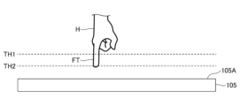
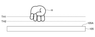
- 4A to 4C are diagrams for explaining an example of a pointing operation and a non-pointing operation.
- 4A to 4C show positions corresponding to a first threshold TH1 and a second threshold TH2 for determining the presence or absence of a hand H by the electrostatic sensor 120. Since the second threshold TH2 is greater than the first threshold TH1, the position corresponding to the second threshold TH2 is closer to the operation surface 105A than the position corresponding to the first threshold TH1. Determining the size of the hand H using such a first threshold TH1 and a second threshold TH2 is equivalent to measuring the cross-sectional area of the hand H.
- FIG. 4A shows a state in which the fingertips FT of the hand H are brought vertically close to the operation surface 105A of the top panel 105 to perform a pointing operation.
- the electrostatic coordinate input device 100 determines whether a pointing operation is being performed with the fingertips FT, or whether a non-pointing operation is being performed with the palm without the fingers being extended, based on the projected area of the hand H from the tip of the fingertips FT of the hand H to a position a predetermined distance away.
- the electrostatic coordinate input device 100 can determine that a pointing operation is being performed with the fingertips FT.
- FIG. 4B shows a state in which a non-pointing operation is being performed by bringing hand H close to operation surface 105A of top panel 105 with all fingers clenched without being extended.
- the projection area of hand H at the position corresponding to first threshold value TH1 becomes large, and therefore electrostatic coordinate input device 100 can determine that a non-pointing operation is being performed.
- FIG. 4C shows a state in which a non-pointing operation is being performed with the fingertip FT of hand H approaching the operation surface 105A of the top panel 105 at an angle.
- One finger is pointing at the operation surface 105A, but because the fingertip FT is at an angle to the operation surface 105A and the palm is also approaching the operation surface 105A, the projected area of hand H at the position corresponding to the first threshold value TH1 becomes large. For this reason, the electrostatic coordinate input device 100 can determine that a non-pointing operation is being performed.
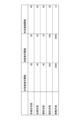
- Fig. 5 is a diagram showing an example of threshold values for determining a distance state, which is a non-detection state, a proximity state, a selection state, a confirmed state, and a contact state.
- FIG. 5 shows the on threshold and off threshold for each of the five distance states.
- the on threshold is a threshold used when determining whether or not a particular distance state exists; when the maximum capacitance detected by electrostatic sensor 120 exceeds the on threshold, the distance state becomes the on threshold distance state.
- the off threshold is a threshold used when determining whether or not a particular distance state exists; when the maximum capacitance detected by electrostatic sensor 120 falls below the off threshold, the distance state no longer corresponds to the off threshold distance state.
- the on threshold is set to a capacitance greater than the off threshold, and hysteresis is provided to stabilize the distance state.
- the on threshold and off threshold are not set.
- the on threshold for the proximity state is 26, and the off threshold is 19.
- the on threshold for the selection state is 103, and the off threshold is 88.
- the on threshold for the confirmed state is 273, and the off threshold is 226.
- the on threshold for the contact state is 1153, and the off threshold is 961.
- the on and off thresholds for the proximity state, selection state, confirmation state, and contact state are set so that the ranges between the on and off thresholds do not overlap with each other.
- the electrostatic coordinate input device 100 uses the on-threshold and off-threshold values shown in FIG. 5 to determine the distance state in the current process according to the distance state in the previous process (previous control cycle).
- the determination process can be summarized as shown in FIG. 6.
- FIG. 6 shows the distance state determined by the electrostatic coordinate input device 100 in relation to the maximum capacitance and the previous distance state.
- the current distance state is determined to be a contact state, regardless of the previous distance state.
- the current distance state is determined to be a contact state.
- the current distance state is determined to be the confirmed state.
- “Equal to or less than the confirmed state” means that the distance state is either the non-detection state, the proximity state, the selection state, or the confirmed state.
- the current distance state is determined to be a confirmed state, regardless of the previous distance state.
- the current distance state is determined to be a confirmed state.
- a confirmed state or greater means that the distance state is either a contact state or a confirmed state.
- the current distance state is determined to be the selected state.
- Equal to or less than the selected state means that the distance state is either the non-detection state, the proximity state, or the selected state.
- the current distance state is determined to be the selected state, regardless of the previous distance state.
- the current distance state is determined to be the selected state.
- the distance state greater than or equal to the selected state means that the distance state is either the contact state, the confirmed state, or the selected state.
- the current distance state is determined to be the proximity state.
- Less than the proximity state means that the distance state is either the non-detection state or the proximity state.
- the current distance state is determined to be a close proximity state, regardless of the previous distance state.
- the current distance state is determined to be the proximity state.
- the proximity state or greater means that the distance state is any of the following states: contact state, confirmed state, selected state, or proximity state.
- the current distance state is determined to be a non-detection state.
- the current distance state is determined to be a non-detection state, regardless of the previous distance state.
- Fig. 7 is a diagram showing a flowchart showing the process executed by the control device 130 of the electrostatic coordinate input device 100.
- the flow shown in Fig. 7 is called and executed by application software (not shown). If the application software is in an input waiting state, the flow shown in Fig. 7 is repeatedly executed from start to end at a predetermined control period.
- the calculation unit 134 acquires the capacitance of each electrode (each of the sensor electrodes 121X and 121Y) (step S1).
- the calculation unit 134 calculates the position (XY coordinates) of the hand H (step S2).
- the position (XY coordinates) of the hand H is the position of the detection point of the maximum capacitance among the capacitances acquired in step S1.
- the calculation unit 134 determines the distance state between the fingertip FT and the operation surface 105A based on the maximum capacitance acquired in step S2 (step S3).
- the process of step S3 is a subroutine process for determining the distance state, which will be described later with reference to FIG. 8.
- the process of step S3 specifies the distance state between the hand H and the operation surface 105A as one of the distance states.
- the calculation unit 134 performs a non-pointing operation determination to determine whether a non-pointing operation is being performed (step S4).
- the processing of step S4 is a subroutine process, which will be described later with reference to FIG. 8.
- the processing of step S4 determines whether a non-pointing operation is being performed with the hand H.
- the calculation unit 134 outputs data representing the position of the hand H (XY coordinates), the maximum capacitance, the distance state, and whether or not a non-pointing operation is performed (step S5).
- step S5 When the calculation unit 134 finishes processing in step S5, it ends the series of processes (END).
- ⁇ Distance State Determination Process> 8 is a flowchart showing an example of the distance state determination process, which is a subroutine process of step S3 in FIG.
- the calculation unit 134 determines whether the maximum capacitance acquired in step S2 exceeds 1153 (step S31). This is to determine whether a contact state exists.
- step S31A If the calculation unit 134 determines that the maximum capacitance exceeds 1153 (S31: Yes), it determines that the distance state is a contact state (step S31A). After completing the process of step S31A, the calculation unit 134 ends the distance state determination process (subroutine process) and advances the flow to step S4.
- step S31 determines whether the maximum capacitance obtained in step S2 exceeds 961 (step S32).
- step S32A If the calculation unit 134 determines that the maximum capacitance exceeds 961 (S32: Yes), it determines whether the previous distance state was a contact state (step S32A).
- step S32A If the calculation unit 134 determines that the previous distance state was a contact state (S32A: Yes), the flow proceeds to step S31A, and the calculation unit 134 determines that the distance state is a contact state (step S31A). When the calculation unit 134 finishes the process of step S31A, the series of processes ends (END).
- step S32 determines in step S32 that the maximum capacitance acquired in step S2 does not exceed 961 (S32: No), or if the calculation unit 134 determines in step S32A that the previous distance state was not a contact state (S32A: No), it determines whether the maximum capacitance acquired in step S2 exceeds 273 (step S33).
- step S33A If the calculation unit 134 determines that the maximum capacitance exceeds 273 (S33: Yes), it determines that the distance state is determined (step S33A). When the calculation unit 134 finishes the process of step S33A, it ends the series of processes (END).
- step S33 determines whether the maximum capacitance obtained in step S2 exceeds 226 (step S34).
- step S34A If the calculation unit 134 determines that the maximum capacitance exceeds 226 (S34: Yes), it determines whether the previous distance state was a contact state or a confirmed state (step S34A).
- step S34B If the calculation unit 134 determines that the previous distance state was a contact state or a confirmed state (S34A: Yes), it determines that the distance state is a confirmed state (step S34B). After completing the process of step S34B, the calculation unit 134 ends the series of processes (END).
- step S34 determines in step S34 that the maximum capacitance does not exceed 226 (S34: No), or if it determines in step S34A that the previous distance state was neither a contact state nor a confirmed state (S34A: No), it determines whether the maximum capacitance acquired in step S2 exceeds 103 (step S35). The previous distance state was not a confirmed state when the previous distance state was equal to or less than the selected state.
- step S35A If the calculation unit 134 determines that the maximum capacitance exceeds 103 (S35: Yes), it determines that the distance state is the selected state (step S35A). When the calculation unit 134 finishes the process of step S35A, it ends the series of processes (END).
- step S35 determines whether the maximum capacitance obtained in step S2 exceeds 88 (step S36).
- step S36A If the calculation unit 134 determines that the maximum capacitance exceeds 88 (S36: Yes), it determines whether the previous distance state was a contact state, a confirmed state, or a selected state (step S36A).
- step S36B If the calculation unit 134 determines that the previous distance state was either the contact state, the confirmed state, or the selected state (S36A: Yes), it determines that the distance state is the selected state (step S36B). After completing the process of step S36B, the calculation unit 134 ends the series of processes (END).
- step S36 determines in step S36 that the maximum capacitance does not exceed 88 (S36: No), or if it determines in step S36A that the previous distance state was not a contact state, a confirmed state, or a selected state (S36A: No), it determines whether the maximum capacitance acquired in step S2 exceeds 26 (step S37). If the previous distance state was not a contact state, a confirmed state, or a selected state, this means that the previous distance state was equal to or less than the proximity state.
- step S37A determines that the distance state is a close proximity state.
- step S37 determines whether the maximum capacitance obtained in step S2 exceeds 19 (step S38).
- step S38A determines whether the previous distance state was a contact state, a confirmed state, a selected state, or a proximity state.
- step S38A determines that the previous distance state was a close proximity state (S38A: Yes)
- step S38B determines that the distance state is a close proximity state (step S38B).
- step S38B After completing the process of step S38B, the calculation unit 134 ends the series of processes (END).
- step S38 determines in step S38 that the maximum capacitance does not exceed 19 (S38: No), or if the calculation unit 134 determines in step S38A that the previous distance state was not a contact state, a confirmed state, a selected state, or a close proximity state (S38A: No), the calculation unit 134 determines that the distance state is a non-detection state (step S39). After completing the process of step S39, the calculation unit 134 ends the series of processes (END).
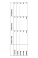
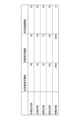
- ⁇ Non-pointing operation determination process> 9 is a diagram showing an example of table data of thresholds used in the non-pointing operation determination process.
- the thresholds used in the non-pointing operation determination process are a non-pointing determination threshold, a pointing determination threshold, and a determination number threshold.
- the non-pointing determination threshold, the pointing determination threshold, and the determination number threshold are provided for each of the non-detection state, the proximity state, the selection state, the confirmation state, and the contact state.
- the non-pointing determination threshold is a threshold used to determine a non-pointing operation based on the maximum capacitance detected by the electrostatic sensor 120.
- the pointing determination threshold is a threshold used to determine a pointing operation based on the maximum capacitance detected by the electrostatic sensor 120.
- the determination number threshold is a threshold used to distinguish between a non-pointing operation and a pointing operation.
- the non-pointing judgment threshold is a threshold used to judge whether a non-pointing operation is being performed based on the capacitance detected by the electrostatic sensor 120 in each of the non-detection state, the proximity state, the selection state, the confirmation state, and the contact state. If the number of detection points where the capacitance exceeds the non-pointing judgment threshold exceeds the judgment number threshold, it is judged that a non-pointing operation is being performed.
- the pointing judgment threshold is a threshold used to judge whether a pointing operation is being performed based on the capacitance detected by the electrostatic sensor 120 in each of the non-detection state, the proximity state, the selection state, the confirmation state, and the contact state. If the number of detection points where the capacitance exceeds the pointing judgment threshold is equal to or less than the judgment number threshold, it is judged that a pointing operation is being performed.
- the determination number threshold is a threshold that is compared with the number of detection points whose capacitance exceeds the pointing determination threshold when determining that a non-pointing operation or a pointing operation is being performed.
- the value of the determination number threshold represents the number of detection points of the electrostatic sensor 120.
- the non-pointing judgment threshold is equal in the non-detection state and the proximity state, but is set to a larger value as the operation state progresses from the non-detection state and the proximity state to the selection state, the confirmation state, and the contact state, in which the hand H is closer to the operation surface 105A. More specifically, the non-pointing judgment threshold is set to 60 in the non-detection state and the proximity state, 90 in the selection state, 220 in the confirmation state, and 2500 in the contact state. In this way, the non-pointing judgment threshold is set to a larger value the shorter the distance represented by the multiple distance states.
- the pointing determination threshold is set to the same value of 50 in the non-detection state, proximity state, selection state, and confirmation state, and is set to 2000 in the contact state.
- the non-pointing judgment threshold in the contact state is greater than the non-pointing judgment threshold in multiple non-touch states (non-detection state, proximity state, selection state, and confirmation state), and the pointing judgment threshold in the contact state is greater than the pointing judgment threshold in multiple non-touch states. Also, the judgment number threshold in the contact state is smaller than the judgment number threshold in multiple non-touch states (non-detection state, proximity state, selection state, and confirmation state).
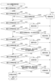
- FIG. 10 is a flowchart showing the non-pointing operation determination process.
- the process shown in FIG. 8 is a subroutine process of step S4 in FIG. 7.
- the calculation unit 134 When the calculation unit 134 starts the non-pointing operation determination process, it sets the non-pointing operation threshold, the pointing operation threshold, and the determination number threshold based on the table data of thresholds shown in FIG. 9 according to the distance state (step S41).
- the calculation unit 134 determines whether the previous operation state was a pointing operation (step S42).
- Step S43A is a process for determining whether a non-pointing operation is being performed.
- step S44A If the calculation unit 134 determines that the number of detection points whose capacitance exceeds the non-pointing operation threshold does not exceed the determination number threshold (S43A: No), it resets the number of non-pointing operations to 0 (step S44A).
- the number of non-pointing operations represents the number of times that a non-pointing operation has been determined to be tentatively performed by determining Yes in step S43A.
- the calculation unit 134 finishes the process of step S44A it ends the series of processes (END).
- step S45A If the calculation unit 134 determines in step S43A that the number of detection points whose capacitance exceeds the non-pointing operation threshold exceeds the determination number threshold (S43A: Yes), it increments the number of non-pointing operations (step S45A).
- the calculation unit 134 determines whether the number of non-pointing operations is three or more (step S46A).
- calculation unit 134 determines that the number of non-pointing operations is not three or more (S46A: No), the calculation unit 134 ends the series of processes (END).
- step S46A determines in step S46A that the number of non-pointing operations is three or more (S46A: Yes)
- the number of non-pointing operations does not reach three unless the result in step S43A is Yes three times in a row.
- step S43A if it is determined in step S43A that the number of detection points where the capacitance exceeds the non-pointing operation threshold exceeds the determination number threshold three consecutive times (S43A: Yes), the operation of the hand H is determined to be a non-pointing operation.
- the operation of the hand H is determined to be a non-pointing operation if it is determined that the number of detection points where the capacitance exceeds the non-pointing operation threshold three consecutive times exceeds the determination number threshold (S43A: Yes).
- the calculation unit 134 resets the number of pointing operations to 0 (step S48A). After completing the process of step S48A, the calculation unit 134 ends the series of processes (END).
- Step S43B is a process for determining whether a non-pointing operation is being performed.
- step S44B If the calculation unit 134 determines that the number of detection points whose capacitance exceeds the pointing operation threshold is not equal to or less than the determination number threshold (S43B: No), it resets the number of pointing operations to 0 (step S44B).
- the number of pointing operations represents the number of times that a pointing operation has been determined to be tentatively performed by determining Yes in step S43B.
- the calculation unit 134 finishes the process of step S44B it ends the series of processes (END).
- step S45B If the calculation unit 134 determines in step S43B that the number of detection points whose capacitance exceeds the non-pointing operation threshold is equal to or less than the determination number threshold (S43B: Yes), it increments the number of pointing operations (step S45B).
- the calculation unit 134 determines whether the number of pointing operations is three or more (step S46B).
- calculation unit 134 determines that the number of pointing operations is not three or more (S46B: No), it ends the series of processes (END).
- step S46B determines in step S46B that the number of pointing operations is three or more (S46B: Yes)
- the number of pointing operations does not reach three unless the determination in step S43B is Yes three times in a row.
- step S43B if it is determined in step S43B that the number of detection points where the capacitance exceeds the pointing operation threshold is equal to or less than the determination number threshold (S43B: Yes) three consecutive times, the operation of the hand H is determined to be a pointing operation.
- the operation of the hand H is determined to be a pointing operation if it is determined that the number of detection points where the capacitance exceeds the pointing operation threshold three consecutive times is equal to or less than the determination number threshold (S43B: Yes).
- the calculation unit 134 resets the number of non-pointing operations to 0 (step S48B). After completing the process of step S48B, the calculation unit 134 ends the series of processes (END).
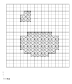
- FIG. 11A to 11D are diagrams showing an example of the distribution of capacitance detected by the electrostatic sensor 120.
- detection points where capacitance exceeding the second threshold value TH2 shown in Figures 4A to 4C is detected are indicated by an x mark
- detection points where capacitance exceeding the first threshold value TH1 but equal to or less than the second threshold value TH2 is indicated by a / mark.
- Detection points where the capacitance is equal to or less than the first threshold value TH1 are indicated by a white mark without an x mark or / mark.
- FIG. 11A there are eight x marks in the upper left corner, and no / marks.
- the x marks are, as an example, detection points where the hand H is in contact, and since the number of x marks is less than the judgment number threshold of 12, the electrostatic coordinate input device 100 determines that a pointing operation in a contact state is being performed. Note that the coordinates of the pointing operation in a contact state are the position of the detection point with the maximum capacitance among the detection points indicated by the eight x marks.
- FIG. 11B there are eight x marks in the upper left and 64 / marks below the center.
- the x marks are, as an example, detection points where the hand H is in contact, and since the number of these marks exceeds the judgment number threshold of 12, the electrostatic coordinate input device 100 determines that a non-pointing operation in a contact state is being performed. Note that the coordinates of the non-pointing operation in a contact state are the position of the detection point with the maximum capacitance among the 72 x marks.
- Fig. 11C there are eight x marks in the upper left corner, and 37 / marks around the x marks.
- the x marks are, as an example, detection points for a hand H in a confirmed state, and since the number of x marks is less than or equal to the judgment number threshold of 90, the electrostatic coordinate input device 100 determines that a confirmed state pointing operation is being performed. Note that the coordinates of the confirmed state pointing operation are the position of the detection point with the maximum capacitance among the detection points indicated by the eight x marks.
- Fig. 11D there are eight x marks in the upper left corner, and 100 / marks around the x marks.
- the x marks are, as an example, detection points for a hand H in a confirmed state, and since the number of x marks exceeds the judgment number threshold of 90, the electrostatic coordinate input device 100 determines that a non-pointing operation in a confirmed state is being performed. Note that the coordinates of the non-pointing operation in a confirmed state are the position of the detection point with the maximum capacitance among the detection points indicated by the eight x marks.
- FIGS. 12A to 12E are diagrams showing an example of the operation of the electrostatic coordinate input device 100.
- Fig. 12A to Fig. 12E a case where a pointing operation is performed will be described.
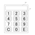
- Fig. 12A to Fig. 12E show simplified views of the numeric keypad and the input content display unit 115 of the electrostatic coordinate input device 100 shown in Fig. 1.
- the electrostatic coordinate input device 100 is in a standby state, the backlight is turned off, and the numeric keypad and the input content display section 115 are dark.
- the distance state is in a non-detection state.
- hand H is close to operation surface 105A, and the distance state is the close proximity state.
- electrostatic coordinate input device 100 switches from the standby state to the activated state, and the backlights of all keys and input content display section 115 are turned on. By turning on the backlight, the numeric keypad area and input content display section 115 are bright.
- the hand H is even closer to the operation surface 105A, and the distance state is the selected state.
- the fingertip FT is positioned on the 7 key, and the backlights of the 7 key and the surrounding 4, 5, 8, C, and 0 keys are turned on, and the backlights of the other keys are turned off.
- the hand H has come even closer to the operation surface 105A, and the distance state is the confirmed state.
- the fingertip FT is positioned on the 7 key, and only the backlight of the 7 key, whose operation has been confirmed, is turned on, and the backlights of the other keys are turned off. This allows the user to visually recognize that the operation on the 7 key has been confirmed.
- the position of the hand H relative to the operation surface 105A is held in the position described in FIG. 12D, waiting for the operation to be confirmed, and the distance state is the confirmed state.
- FIG. 12E the operation has been confirmed by continuing to hold the position of hand H relative to operation surface 105A in the position described in FIG. 12D.
- Fingertip FT is positioned on the 7 key, and by confirming the operation, 7 is displayed in input content display section 115.
- FIGS. 13A to 13F are diagrams showing an example of the operation of the electrostatic coordinate input device 100.
- FIG. 13A to 13F a case is explained in which, after the input of the number 7 is confirmed as described in FIG. 12E, the hand H is sufficiently removed from the operation surface 105A and then the non-pointing operation shown in FIG. 4C is performed.
- the non-pointing operation shown in FIG. 4C is a non-pointing operation in which the fingertip FT is at an angle to the operation surface 105A and the palm also approaches the operation surface 105A.
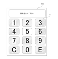
- the numeric keypad portion and the input content display unit 115 of the electrostatic coordinate input device 100 shown in FIG. 1 are shown in simplified form.
- the electrostatic coordinate input device 100 is in a non-detection state, so the backlight for the numeric keypad is off and dark, but the backlight for the input content display unit 115 is on to display the input content.
- the hand H performing the non-pointing operation is in close proximity to the operation surface 105A, and the distance state is in the close proximity state.
- the electrostatic coordinate input device 100 turns on the backlights of all keys and the input content display unit 115, but since the electrostatic coordinate input device 100 has detected that a non-pointing operation is being performed, a warning message "Please bring your finger up close" is displayed on the input content display unit 115. This is to encourage the user to perform the pointing operation.
- the non-pointing hand H approaches the operation surface 105A even closer, and the distance state is the selected state.
- the maximum capacitance is located above the 5 key, but because this is a non-pointing operation, the backlights of the 7 key and the surrounding 4, 5, 8, C, and 0 keys are turned on, and the backlights of the other keys are turned off.
- the hand H is even closer to the operation surface 105A, and the distance state is determined.
- the fingertip FT is positioned on the 5 key, and only the backlight of the 5 key is turned on, while the backlights of the other keys are turned off. Even in this state, the fingertip FT is at an angle, so the input content display unit 115 displays the warning message "Please raise your fingertip.”
- FIG. 13E shows a state in which the state shown in FIG. 13D continues and the time required to confirm the operation has passed, but since it is a non-pointing operation, the operation is not confirmed. Even in this state, the fingertip FT is at an angle, so the input content display unit 115 displays the warning message "Please raise your fingertip.”
- FIG. 13F shows the state where fingertip FT is raised from the state described in FIG. 13E toward operation surface 105A. By raising fingertip FT, the operation is confirmed, and 5 is displayed in addition to 7 in the input content display section 115.
- the electrostatic coordinate input device 100 includes an operation surface 105A, a plurality of sensor electrodes 121X and 121Y arranged on the rear side of the operation surface 105A, a measurement circuit (such as an AD conversion unit 132) that measures the capacitance of each of the plurality of sensor electrodes 121X and 121Y, and a calculation unit 134 that calculates the position of a pointer based on the plurality of capacitances measured by the measurement circuit (such as the AD conversion unit 132).
- a measurement circuit such as an AD conversion unit 132
- the calculation unit 134 that calculates the position of a pointer based on the plurality of capacitances measured by the measurement circuit (such as the AD conversion unit 132).
- the calculation unit 134 calculates the maximum capacitance between the pointer and the sensor electrodes 121X and 121Y based on the plurality of capacitances, sets a non-pointing determination threshold used to determine that a non-pointing operation of the pointer is not a pointing operation based on the maximum capacitance, and determines that the operation of the pointer is a non-pointing operation when the number of capacitances exceeding the non-pointing determination threshold among the plurality of capacitances exceeds a determination number threshold.
- the non-pointing judgment threshold based on the maximum capacitance, it is possible to measure the cross-sectional area at a position a certain distance away from the operation surface 105A, based on the position of the hand H closest to the operation surface 105A. In other words, if the cross-sectional area at a position several centimeters away from the fingertip FT is equal to or greater than a predetermined value, it is deemed to be a non-pointing operation where the finger is not pointing at the operation surface 105A. By accurately determining the state where the finger is not pointing at the operation surface 105A even without contact, erroneous operation can be prevented.
- an electrostatic coordinate input device 100 that can determine with high accuracy whether or not an operation such as contact or proximity has occurred based on the distance between the indicator and the device, and can suppress erroneous operations.
- the calculation unit 134 also sets a pointing determination threshold used to determine whether the operation of the indicator is a pointing operation based on the maximum capacitance, and if the number of capacitances that exceed the pointing determination threshold among the multiple capacitances is equal to or less than the determination number threshold, it determines that the operation of the indicator is a pointing operation. Therefore, pointing operations can also be determined with high accuracy.
- the calculation unit 134 also determines which of a plurality of distance states the distance between the pointer and the operation surface 105A corresponds to based on the maximum capacitance, and the non-pointing determination threshold, the pointing determination threshold, and the determination number threshold are determined for each of the plurality of distance states, and the non-pointing determination threshold is set to a larger value the shorter the distance represented by the plurality of distance states. Therefore, it is possible to provide an electrostatic coordinate input device 100 that can easily set an appropriate non-pointing determination threshold, can accurately determine the presence or absence of an operation such as contact or proximity depending on the distance from the pointer, and can suppress erroneous operations.
- the multiple distance states include a contact state indicating that the operation surface 105A and the pointer are in contact, and multiple non-contact states indicating that the operation surface 105A and the pointer are not in contact, and the non-pointing judgment threshold in the contact state is larger than the non-pointing judgment threshold in the multiple non-contact states, the pointing judgment threshold in the contact state is larger than the pointing judgment threshold in the multiple non-contact states, and the judgment number threshold in the contact state is smaller than the judgment number threshold in the multiple non-contact states.
- a contact state a pointing operation and a non-pointing operation are distinguished by the contact area.
- the judgment accuracy can be improved by making the non-pointing operation threshold and the pointing operation threshold larger than the non-pointing operation threshold and the pointing operation threshold in the non-contact state.
- the judgment accuracy can be improved by making the judgment number threshold in the contact state smaller than the judgment number threshold in the multiple non-contact states.
- the pointing judgment thresholds in multiple non-contact states are equal to each other, and the judgment number thresholds in multiple non-contact states are equal to each other. For this reason, this is particularly useful when applying an operation method that requires the operation of removing the hand H from the operation surface 105A once when a non-pointing operation is detected.
- the multiple non-touch states from shortest to longest distances represented by the multiple distance states, are a confirmation state in which the input content is confirmed, a selection state in which an input candidate is selected, a proximity state in which the input candidate is in proximity, and a non-detection state in which the pointer is not detected, and the non-pointing judgment threshold for the non-detection state is the same value as the non-pointing judgment threshold for the proximity state, the pointing judgment threshold for the non-detection state is the same value as the pointing judgment threshold for the proximity state, and the judgment number threshold for the non-detection state is the same value as the judgment number threshold for the proximity state.
- the calculation unit 134 determines that the operation of the indicator is a non-pointing operation when the number of capacitances exceeding the non-pointing judgment threshold exceeds the judgment number threshold for a predetermined number of consecutive times in a state where the operation of the indicator is determined to be a pointing operation, determines that the operation of the indicator is a non-pointing operation until the number of capacitances exceeding the non-pointing judgment threshold exceeds the judgment number threshold for a predetermined number of consecutive times in a state where the operation of the indicator is determined to be a non-pointing operation, determines that the operation of the indicator is a pointing operation when the number of capacitances exceeding the pointing judgment threshold is equal to or less than the judgment number threshold for a predetermined number of consecutive times in a state where the operation of the indicator is determined to be a non-pointing operation, and determines that the operation of the indicator is a non-pointing operation until the number of capacitances exceeding the pointing judgment threshold is equal to or less than the judgment number threshold for a predetermined number of consecutive times in
- the display unit (input content display unit 115) is further included, and when the calculation unit 134 determines that the operation of the pointer is a non-pointing operation, it displays a message on the display unit (input content display unit 115) requesting the user to perform a pointing operation with the pointer. This allows the user to be guided to hold up the fingertip FT and perform the operation correctly with a pointing operation, thereby reducing erroneous operations.
- the operation determination method in the electrostatic coordinate input device includes an operation surface 105A, a plurality of sensor electrodes 121X and 121Y arranged on the back side of the operation surface 105A, a measurement circuit (such as an AD conversion unit 132) that measures the capacitance of each of the plurality of sensor electrodes 121X and 121Y, and a calculation unit 134 that calculates the position of the indicator based on the plurality of capacitances measured by the measurement circuit (such as the AD conversion unit 132).
- a measurement circuit such as an AD conversion unit 132
- the calculation unit 134 that calculates the position of the indicator based on the plurality of capacitances measured by the measurement circuit (such as the AD conversion unit 132).
- the maximum capacitance between the indicator and the sensor electrodes 121X and 121Y is calculated based on the plurality of capacitances, a non-pointing determination threshold is set based on the maximum capacitance to be used to determine whether the indicator is a non-pointing operation that is not a pointing operation, and when the number of capacitances among the plurality of capacitances that exceed the non-pointing determination threshold exceeds the determination number threshold, the operation of the indicator is determined to be a non-pointing operation.
- an operation determination method for an electrostatic coordinate input device that can determine with high accuracy whether an operation such as contact or proximity has occurred based on the distance between the indicator and the device, and can suppress erroneous operations.
- ⁇ Modification> 14A to 14C are diagrams showing modified examples of table data of threshold values used in the non-pointing operation determination process.
- the judgment number thresholds for multiple non-contact states are equal to each other, and the pointing judgment threshold for multiple non-contact states is larger as the distances represented by the multiple distance states are shorter.
- the pointing determination thresholds for the selected state and the confirmed state are set to be larger, at 70 and 190, respectively.
- the pointing judgment thresholds for multiple non-contact states are equal to each other, and the judgment number threshold for multiple non-contact states is smaller as the distances represented by the multiple distance states are shorter.
- the values of the judgment number threshold for the selected state and the confirmed state are smaller, and are set to 56 and 30, respectively.
- the judgment number threshold is set to be larger as the state progresses from the contact state to the confirmed state, selected state, proximity state, and non-detection state. Therefore, the farther the hand H is from the operation surface 105A, the larger the cross-sectional area is at which it is possible to distinguish between pointing and non-pointing operations.
- the table data shown in FIG. 14C has a larger pointing determination threshold and a smaller determination number threshold as the distances represented by the multiple distance states become shorter.
- the data configuration is a combination of the table data shown in FIG. 14A and FIG. 14B.
- the pointing judgment thresholds for the selected state and confirmed state are increased, being set to 70 and 190, respectively.
- the judgment number thresholds for the selected state and confirmed state are decreased, being set to 56 and 30, respectively.
- FIG. 15 is a flowchart showing a modified example of the non-pointing operation determination process.
- the flowchart shown in FIG. 15 is obtained by replacing step S41 in the flowchart showing the non-pointing operation determination process shown in FIG. 10 with step S41M.
- the processes from step S42 onwards are the same as those in the flowchart showing the non-pointing operation determination process shown in FIG. 10. For this reason, the process of step S41M will be explained here.
- the calculation unit 134 sets the non-pointing operation threshold to a value obtained by multiplying the maximum capacitance value detected by the electrostatic sensor 120 in that control cycle by a coefficient of 0.8, sets the pointing operation threshold to a value obtained by multiplying the maximum capacitance value detected by the electrostatic sensor 120 in that control cycle by a coefficient of 0.5, and sets the judgment number threshold to a value obtained by dividing 10,000 by the maximum capacitance value detected by the electrostatic sensor 120 in that control cycle (step S41M).
- the non-pointing judgment threshold is a value proportional to the maximum capacitance.
- the coefficient by which the maximum capacitance is multiplied is not limited to 0.8 and may be set to any appropriate value.
- the pointing judgment threshold is a value proportional to the maximum capacitance.
- the coefficient by which the maximum capacitance is multiplied is not limited to 0.5 and may be set to any appropriate value as long as it is smaller than the coefficient by which the non-pointing operation threshold is multiplied.
- the pointing judgment threshold is a value larger than the non-pointing judgment threshold.
- the judgment number threshold is a value inversely proportional to the maximum capacitance. For this reason, a non-pointing operation can be judged without using table data of thresholds such as those shown in FIG. 9 and FIG. 14A to FIG. 14C.
- Electrostatic coordinate input device 101 Housing 105 Top panel 105A Operation surface 110 Display device 111 GUI button 115 Input content display unit 120 Electrostatic sensor 121X Sensor electrode 121Y Sensor electrode 122X Wiring 122Y Wiring 130 Control device 131 Main control unit 132 AD conversion unit 133 Counter 134 Calculation unit 135 Operation control unit 136 Display control unit 137 Memory
Landscapes
- Engineering & Computer Science (AREA)
- General Engineering & Computer Science (AREA)
- Theoretical Computer Science (AREA)
- Human Computer Interaction (AREA)
- Physics & Mathematics (AREA)
- General Physics & Mathematics (AREA)
- Position Input By Displaying (AREA)
Abstract
Description
図1及び図2は、実施形態の静電式座標入力装置100の構成の一例を示す図である。図1は、静電式座標入力装置100が動作状態であり、表示装置110が入力画像を表示している状態を示す。表示装置110が入力画像を表示しているとき、静電式座標入力装置100が入力モードの状態である。入力モードは、静電式座標入力装置100に対して操作入力が可能なモードである。図2は、静電式座標入力装置100が待機状態であり、表示装置110が待機画像を表示している状態を示す。表示装置110が待機画像を表示しているときは、静電式座標入力装置100が省電力モードの状態である。待機状態では、表示装置110は全体的にグレーに表示され、消費電力が少ない状態である。図3は、静電式座標入力装置100の静電センサ120及び制御装置130の構成の一例を示す図である。表示装置110は表示部の一例であり、静電センサ120は検出部の一例であり、制御装置130は制御部の一例である。
静電式座標入力装置100は、筐体101、トップパネル105、表示装置110、静電センサ120、及び制御装置130を含む。図1及び図2では制御装置130(図3参照)を省略するが、制御装置130は、一例として筐体101の内部で表示装置110及び静電センサ120の下側に設けられる。静電式座標入力装置100は、図3に示す静電センサ120及び制御装置130を含む。
筐体101は、表示装置110、静電センサ120、及び制御装置130を収容する樹脂製又は金属製等のケースである。表示装置110は、一例として透明な静電センサ120の下側に配置され、筐体101の上部にある開口部に設けられる透明なトップパネル105の上面である操作面105Aを介して視認可能である。
静電式座標入力装置100は、利用者の手等の指示体が操作面105Aに対して非接触の状態と、利用者の手等の指示体が操作面105Aに対して接触した状態との両方の状態で操作可能である。
表示装置110は、一例として液晶ディスプレイや有機EL(Electroluminescence)ディスプレイ等である。表示装置110は、GUI(Graphic User Interface)を実現するための表示である。表示装置110は、GUIボタン111の画像と、カーソルと、入力内容を表示する入力内容表示部115の画像とを表示する。GUIボタン111は、操作部の一例であり、一例として平面視でマトリクス状に配置される。また、GUIボタン111は、一例として押しボタンを模した円形である。
静電センサ120は、表示装置110の上に重ねて配置され、図3に示すように、X方向に延在する複数のセンサ電極121Xと、Y方向に延在する複数のセンサ電極121Yとを有する。センサ電極121X、121Yは、検出部の電極の一例であり、配線122X、122Yを介して制御装置130にそれぞれ接続されている。このような静電センサ120は、一例として透明ガラスの表面にITO(Indium Tin Oxide)等の透明導電膜を形成し、センサ電極121X、121Y及び配線122X、122Yにパターニングしたものを用いることができる。静電センサ120が検出する静電容量は、制御装置130に入力される。静電センサ120が検出する静電容量は、静電センサ120の検出結果の一例である。
制御装置130は、CPU(Central Processing Unit)、RAM(Random Access Memory)、ROM(Read Only Memory)、入出力インターフェース、及び内部バス等を含むコンピュータによって実現される。
図4A乃至図4Cは、指差操作及び非指差操作の一例を説明する図である。図4A乃至図4Cには、静電センサ120で手Hの有無を判定するための第1閾値TH1及び第2閾値TH2に対応する位置を示す。第1閾値TH1よりも第2閾値TH2の方が大きいため、第1閾値TH1に対応する位置よりも第2閾値TH2に対応する位置の方が操作面105Aに近い。このような第1閾値TH1及び第2閾値TH2を用いて手Hの大きさを判定することは、手Hの断面積を測定していることに等しい。
図5は、距離状態判定用の閾値の一例を示す図である。図5には、非検出状態、近接状態、選択状態、確定状態、及び接触状態の5つの距離状態を判定するための閾値を示す図である。
図7は、静電式座標入力装置100の制御装置130が実行する処理を表すフローチャートを示す図である。図7に示すフローは、図示せぬアプリケーションソフトに呼び出されて実行される。アプリケーションソフトが入力待ちの状態であれば、図7に示すフローは、スタートからエンドまで所定の制御周期で繰り返し実行される。
図8は、距離状態判定処理の一例を示すフローチャートである。図8に示す処理は、図7のステップS3のサブルーチン処理である。
図9は、非指差操作判定処理に用いる閾値のテーブルデータの一例を示す図である。非指差操作判定処理に用いる閾値は、非指差判定閾値、指差判定閾値、及び判定個数閾値である。非指差判定閾値、指差判定閾値、及び判定個数閾値は、非検出状態、近接状態、選択状態、確定状態、及び接触状態の各々について設けられている。
図11A乃至図11Dは、静電センサ120が検出する静電容量の分布の一例を示す図である。図11A乃至図11Dには、一例として、センサ電極121X及び121Yが平面視で交差する点が、X方向に18個×Y方向に18個あり、静電センサ120は18×18の324箇所の検出点で静電容量を検出可能であるとする。このため、図11A乃至図11Dには横18個×縦18個の324個の枠を示す。
図12A乃至図12Eは、静電式座標入力装置100の動作例を示す図である。図12A乃至図12Eでは、指差操作が行われる場合について説明する。図12A乃至図12Eには、図1に示す静電式座標入力装置100のテンキーの部分、及び、入力内容表示部115を簡略化して示す。
静電式座標入力装置100は、操作面105Aと、操作面105Aの裏側に配列される複数のセンサ電極121X及び121Yと、複数のセンサ電極121X及び121Yの各々の静電容量を測定する測定回路(AD変換部132等)と、測定回路(AD変換部132等)によって測定される複数の静電容量に基づいて指示体の位置を算出する算出部134とを備える。算出部134は、複数の静電容量に基づいて、指示体とセンサ電極121X及び121Yとの間の最大の静電容量を算出し、最大の静電容量に基づいて、指示体の指差操作ではない非指差操作を判定するために用いる非指差判定閾値を設定し、複数の静電容量のうち、非指差判定閾値を超える静電容量の個数が、判定個数閾値を超えると、指示体の操作は非指差操作であると判定する。
図14A乃至図14Cは、非指差操作判定処理に用いる閾値のテーブルデータの変形例を示す図である。
101 筐体
105 トップパネル
105A 操作面
110 表示装置
111 GUIボタン
115 入力内容表示部
120 静電センサ
121X センサ電極
121Y センサ電極
122X 配線
122Y 配線
130 制御装置
131 主制御部
132 AD変換部
133 カウンタ
134 算出部
135 動作制御部
136 表示制御部
137 メモリ
Claims (15)
- 操作面と、
前記操作面の裏側に配列される複数のセンサ電極と、
前記複数のセンサ電極の各々の静電容量を測定する測定回路と、
前記測定回路によって測定される複数の静電容量に基づいて指示体の位置を算出する算出部と
を備え、
前記算出部は、
前記複数の静電容量に基づいて、前記指示体と前記センサ電極との間の最大の静電容量を算出し、
前記最大の静電容量に基づいて、前記指示体の指差操作ではない非指差操作を判定するために用いる非指差判定閾値を設定し、
前記複数の静電容量のうち、前記非指差判定閾値を超える静電容量の個数が、判定個数閾値を超えると、前記指示体の操作は前記非指差操作であると判定する、
静電式座標入力装置。 - 前記算出部は、前記最大の静電容量に基づいて、前記指示体の操作が前記指差操作であることを判定するために用いる指差判定閾値を設定し、
前記複数の静電容量のうち、前記指差判定閾値を超える静電容量の個数が、前記判定個数閾値以下であれば、前記指示体の操作は前記指差操作であると判定する、請求項1に記載の静電式座標入力装置。 - 前記算出部は、前記最大の静電容量に基づいて、前記指示体と前記操作面との間の距離が、複数の距離状態のいずれに該当するかを判定し、
前記非指差判定閾値と、前記指差判定閾値と、前記判定個数閾値は、前記複数の距離状態の各々について定められており、
前記非指差判定閾値は、前記複数の距離状態が表す距離が短いほど、大きな値に設定される、請求項2に記載の静電式座標入力装置。 - 前記複数の距離状態は、前記操作面と前記指示体とが接触していることを示す接触状態と、前記操作面と前記指示体とが接触していないことを示す複数の非接触状態とを含み、
前記接触状態における前記非指差判定閾値は、前記複数の非接触状態における前記非指差判定閾値よりも大きく、
前記接触状態における前記指差判定閾値は、前記複数の非接触状態における前記指差判定閾値よりも大きく、
前記接触状態における前記判定個数閾値は、前記複数の非接触状態における前記判定個数閾値よりも小さい、請求項3に記載の静電式座標入力装置。 - 前記複数の非接触状態における前記指差判定閾値は互いに等しく、
前記複数の非接触状態における前記判定個数閾値は互いに等しい、請求項4に記載の静電式座標入力装置。 - 前記複数の非接触状態における前記判定個数閾値は互いに等しく、
前記複数の非接触状態における前記指差判定閾値は、前記複数の距離状態が表す距離が短いほど大きい、請求項4に記載の静電式座標入力装置。 - 前記複数の非接触状態における前記指差判定閾値は互いに等しく、
前記複数の非接触状態における前記判定個数閾値は、前記複数の距離状態が表す距離が短いほど小さい、請求項4に記載の静電式座標入力装置。 - 前記複数の距離状態が表す距離が短いほど、前記指差判定閾値が大きく、前記判定個数閾値が小さい、請求項4に記載の静電式座標入力装置。
- 前記複数の非接触状態は、前記複数の距離状態が表す距離が短い方から長い方にかけて、入力内容を確定する確定状態と、入力候補を選択する選択状態と、前記入力候補に近接する近接状態と、前記指示体が検出されない非検出状態とであり、
前記非検出状態の前記非指差判定閾値と、前記近接状態の前記非指差判定閾値とは同一値であり、
前記非検出状態の前記指差判定閾値と、前記近接状態の前記指差判定閾値とは同一値であり、
前記非検出状態の前記判定個数閾値と、前記近接状態の前記判定個数閾値とは同一値である、請求項4に記載の静電式座標入力装置。 - 前記非指差判定閾値は、前記最大の静電容量に比例した値である、請求項2に記載の静電式座標入力装置。
- 前記指差判定閾値は、前記最大の静電容量に比例した値であり、
前記指差判定閾値は、前記非指差判定閾値より大きな値である、請求項10に記載の静電式座標入力装置。 - 前記判定個数閾値は、前記最大の静電容量に反比例した値である、請求項10に記載の静電式座標入力装置。
- 前記算出部は、
前記指示体の操作は前記指差操作であると判定している状態において、前記非指差判定閾値を超える静電容量の個数が、前記判定個数閾値を超える状態が所定回数連続して成立したら、前記指示体の操作は前記非指差操作であると判定し、
前記指示体の操作は前記指差操作であると判定している状態において、前記非指差判定閾値を超える静電容量の個数が、前記判定個数閾値を超える状態が所定回数連続して成立するまで、前記指示体の操作は前記非指差操作であると判定し、
前記指示体の操作は前記非指差操作であると判定している状態において、前記指差判定閾値を超える静電容量の個数が、前記判定個数閾値以下の状態が所定回数連続して成立したら、前記指示体の操作は前記指差操作であると判定し、
前記指示体の操作は前記非指差操作であると判定している状態において、前記指差判定閾値を超える静電容量の個数が、前記判定個数閾値以下の状態が所定回数連続して成立するまで、前記指示体の操作は前記非指差操作であると判定する、請求項2乃至12のいずれか1項に記載の静電式座標入力装置。 - 表示部をさらに含み、
前記算出部は、前記指示体の操作は前記非指差操作であると判定している状態において、前記指示体で前記指差操作を行うことを求めるメッセージを前記表示部に表示する、請求項13に記載の静電式座標入力装置。 - 操作面と、
前記操作面の裏側に配列される複数のセンサ電極と、
前記複数のセンサ電極の各々の静電容量を測定する測定回路と、
前記測定回路によって測定される複数の静電容量に基づいて指示体の位置を算出する算出部と
を備える静電式座標入力装置における操作判定方法であって、
前記複数の静電容量に基づいて、前記指示体と前記センサ電極との間の最大の静電容量を算出し、
前記最大の静電容量に基づいて、前記指示体の指差操作ではない非指差操作を判定するために用いる非指差判定閾値を設定し、
前記複数の静電容量のうち、前記非指差判定閾値を超える静電容量の個数が、判定個数閾値を超えると、前記指示体の操作は前記非指差操作であると判定する、
静電式座標入力装置における操作判定方法。
Priority Applications (3)
| Application Number | Priority Date | Filing Date | Title |
|---|---|---|---|
| JP2024557051A JP7838110B2 (ja) | 2022-11-07 | 2023-09-20 | 静電式座標入力装置、及び、静電式座標入力装置における操作判定方法 |
| DE112023004732.4T DE112023004732T5 (de) | 2022-11-07 | 2023-09-20 | Elektrostatische koordinaten eingabevorrichtung und verfahren zum bestimmen einer operation in einer elektrostatischen koordinaten eingabevorrichtung |
| CN202380074742.6A CN120092224A (zh) | 2022-11-07 | 2023-09-20 | 静电式坐标输入装置以及静电式坐标输入装置中的操作判定方法 |
Applications Claiming Priority (2)
| Application Number | Priority Date | Filing Date | Title |
|---|---|---|---|
| JP2022178084 | 2022-11-07 | ||
| JP2022-178084 | 2022-11-07 |
Publications (1)
| Publication Number | Publication Date |
|---|---|
| WO2024101005A1 true WO2024101005A1 (ja) | 2024-05-16 |
Family
ID=91032150
Family Applications (1)
| Application Number | Title | Priority Date | Filing Date |
|---|---|---|---|
| PCT/JP2023/034156 Ceased WO2024101005A1 (ja) | 2022-11-07 | 2023-09-20 | 静電式座標入力装置、及び、静電式座標入力装置における操作判定方法 |
Country Status (4)
| Country | Link |
|---|---|
| JP (1) | JP7838110B2 (ja) |
| CN (1) | CN120092224A (ja) |
| DE (1) | DE112023004732T5 (ja) |
| WO (1) | WO2024101005A1 (ja) |
Citations (3)
| Publication number | Priority date | Publication date | Assignee | Title |
|---|---|---|---|---|
| JP2015141425A (ja) * | 2014-01-27 | 2015-08-03 | アルプス電気株式会社 | タッチパッド入力装置およびタッチパッド制御プログラム |
| JP2017138816A (ja) * | 2016-02-04 | 2017-08-10 | アルプス電気株式会社 | 静電入力装置、静電入力装置用プログラム |
| JP2018032251A (ja) * | 2016-08-25 | 2018-03-01 | レノボ・シンガポール・プライベート・リミテッド | 情報処理装置、タッチパネル感度制御方法、及びプログラム |
Family Cites Families (3)
| Publication number | Priority date | Publication date | Assignee | Title |
|---|---|---|---|---|
| US20100073318A1 (en) | 2008-09-24 | 2010-03-25 | Matsushita Electric Industrial Co., Ltd. | Multi-touch surface providing detection and tracking of multiple touch points |
| JP5798103B2 (ja) * | 2012-11-05 | 2015-10-21 | 株式会社Nttドコモ | 端末装置、画面表示方法、プログラム |
| WO2022044569A1 (ja) | 2020-08-24 | 2022-03-03 | アルプスアルパイン株式会社 | 静電入力装置、及び、入力判定方法 |
-
2023
- 2023-09-20 DE DE112023004732.4T patent/DE112023004732T5/de active Pending
- 2023-09-20 JP JP2024557051A patent/JP7838110B2/ja active Active
- 2023-09-20 WO PCT/JP2023/034156 patent/WO2024101005A1/ja not_active Ceased
- 2023-09-20 CN CN202380074742.6A patent/CN120092224A/zh active Pending
Patent Citations (3)
| Publication number | Priority date | Publication date | Assignee | Title |
|---|---|---|---|---|
| JP2015141425A (ja) * | 2014-01-27 | 2015-08-03 | アルプス電気株式会社 | タッチパッド入力装置およびタッチパッド制御プログラム |
| JP2017138816A (ja) * | 2016-02-04 | 2017-08-10 | アルプス電気株式会社 | 静電入力装置、静電入力装置用プログラム |
| JP2018032251A (ja) * | 2016-08-25 | 2018-03-01 | レノボ・シンガポール・プライベート・リミテッド | 情報処理装置、タッチパネル感度制御方法、及びプログラム |
Also Published As
| Publication number | Publication date |
|---|---|
| JP7838110B2 (ja) | 2026-03-31 |
| JPWO2024101005A1 (ja) | 2024-05-16 |
| DE112023004732T5 (de) | 2025-08-28 |
| CN120092224A (zh) | 2025-06-03 |
Similar Documents
| Publication | Publication Date | Title |
|---|---|---|
| CA2067689C (en) | Apparatus and method for inputting data | |
| KR950012489B1 (ko) | 데이타 처리 시스템 및 그 처리 시간 감소 방법 | |
| US9575568B2 (en) | Multi-function keys providing additional functions and previews of functions | |
| US20090009482A1 (en) | Touch sensor pad user input device | |
| US20120242594A1 (en) | Input device and input method | |
| US20110069021A1 (en) | Reducing false touchpad data by ignoring input when area gesture does not behave as predicted | |
| US20090066659A1 (en) | Computer system with touch screen and separate display screen | |
| US20100253630A1 (en) | Input device and an input processing method using the same | |
| JP7666779B2 (ja) | 入力装置 | |
| US8970498B2 (en) | Touch-enabled input device | |
| JP6293209B2 (ja) | 情報処理装置、誤操作抑制方法、及びプログラム | |
| US11789559B2 (en) | Input device | |
| KR101438231B1 (ko) | 하이브리드 터치스크린을 구비한 단말 장치 및 그 제어방법 | |
| JP7838110B2 (ja) | 静電式座標入力装置、及び、静電式座標入力装置における操作判定方法 | |
| JP2014081723A (ja) | 抵抗膜式タッチパネルを備えた電子機器 | |
| US20080158187A1 (en) | Touch control input system for use in electronic apparatuses and signal generation method thereof | |
| TWI502416B (zh) | 觸控面板的感測裝置以及其感應方法 | |
| US12366939B2 (en) | Coordinate input apparatus | |
| WO2024154400A1 (ja) | 座標入力装置 | |
| US20180292924A1 (en) | Input processing apparatus | |
| JP5108824B2 (ja) | 入力処理装置 | |
| JP2025077306A (ja) | 操作検出装置 | |
| JP2018032122A (ja) | 表示操作装置 | |
| JP2025150570A (ja) | 静電入力装置 | |
| KR20100005305A (ko) | 순차로 인가 또는 해제되는 복수의 접촉 입력을 인식하는방법 |
Legal Events
| Date | Code | Title | Description |
|---|---|---|---|
| 121 | Ep: the epo has been informed by wipo that ep was designated in this application |
Ref document number: 23888358 Country of ref document: EP Kind code of ref document: A1 |
|
| WWE | Wipo information: entry into national phase |
Ref document number: 2024557051 Country of ref document: JP |
|
| WWE | Wipo information: entry into national phase |
Ref document number: 202380074742.6 Country of ref document: CN |
|
| WWP | Wipo information: published in national office |
Ref document number: 202380074742.6 Country of ref document: CN |
|
| WWE | Wipo information: entry into national phase |
Ref document number: 112023004732 Country of ref document: DE |
|
| WWP | Wipo information: published in national office |
Ref document number: 112023004732 Country of ref document: DE |
|
| 122 | Ep: pct application non-entry in european phase |
Ref document number: 23888358 Country of ref document: EP Kind code of ref document: A1 |