WO2024097789A2 - Porous hybrid metal halide semiconductors - Google Patents
Porous hybrid metal halide semiconductors Download PDFInfo
- Publication number
- WO2024097789A2 WO2024097789A2 PCT/US2023/078399 US2023078399W WO2024097789A2 WO 2024097789 A2 WO2024097789 A2 WO 2024097789A2 US 2023078399 W US2023078399 W US 2023078399W WO 2024097789 A2 WO2024097789 A2 WO 2024097789A2
- Authority
- WO
- WIPO (PCT)
- Prior art keywords
- dhs
- semiconductor material
- porous semiconductor
- cryptand
- linker molecule
- Prior art date
- Legal status (The legal status is an assumption and is not a legal conclusion. Google has not performed a legal analysis and makes no representation as to the accuracy of the status listed.)
- Ceased
Links
Classifications
-
- H—ELECTRICITY
- H10—SEMICONDUCTOR DEVICES; ELECTRIC SOLID-STATE DEVICES NOT OTHERWISE PROVIDED FOR
- H10K—ORGANIC ELECTRIC SOLID-STATE DEVICES
- H10K85/00—Organic materials used in the body or electrodes of devices covered by this subclass
- H10K85/50—Organic perovskites; Hybrid organic-inorganic perovskites [HOIP], e.g. CH3NH3PbI3
-
- C—CHEMISTRY; METALLURGY
- C07—ORGANIC CHEMISTRY
- C07F—ACYCLIC, CARBOCYCLIC OR HETEROCYCLIC COMPOUNDS CONTAINING ELEMENTS OTHER THAN CARBON, HYDROGEN, HALOGEN, OXYGEN, NITROGEN, SULFUR, SELENIUM OR TELLURIUM
- C07F7/00—Compounds containing elements of Groups 4 or 14 of the Periodic Table
- C07F7/003—Compounds containing elements of Groups 4 or 14 of the Periodic Table without C-Metal linkages
Definitions
- the aristotype 3D AMX 3 perovskite structure comprises corner-sharing [MX 6 ] 4- octahedra that propagates along the three spatial directions, whereas in the formed cubo- octahedral cavities A + cations reside charge-balancing the structure.
- (DAO)Sn2I6 (DAO, 1,8- octyldiammonium) maintains its structural integrity for 15h
- [N-methyldabconium]PbI3 which is water stable for one month.
- porous semiconductor material which may include a metal halide and an organic linker molecule.
- the porous semiconductor material including the organic liner molecule, wherein the organic linker molecule may have a size-selective cavity, providing porosity to the semiconductor material.
- a method of making the porous semiconductor material is also disclosed.
- the porous semiconductor material provides solutions to unmet needs in the fields of carrier transport properties, enhanced photoconductivity, solution processability, water stability, fine tunable optical bandgap, increase in the photoluminescence (PL), second harmonic generation (SHG) and terahertz (THZ) emission intensity, and thermal stability, wherein the inherent features of the material also rendered them proper for unconventional semiconductor applications, such as photocatalysis, energy storage, sensors, antibacterial agents.
- the techniques described herein relate to a porous semiconductor material including: a metal halide; and an organic linker molecule.
- the techniques described herein relate to the porous semiconductor material of any of the previous claims, wherein the semiconductor material includes (CRB)Pb2Cl13(H3O), (CRT)(H3O)2Pb2Cl14, (CRT)(H3O)2Pb2Cl14, (CRT)(H3O)PbBr11, (DHT)(K)(H3O)Pb3Br10, (DHS)2Pb5Br14, (DHS)2Pb5Cl14, (DHS)Sb2Br7, (DHS)SnCl4, (DHS)SnBr 4 , (DHS) 2 SbBr 7 , (DHS)Sb 2 C l8 , (DHS)Bi 2 I 8 , or a combination thereof.
- the semiconductor material includes (CRB)Pb2Cl13(H3O), (CRT)(H3O)2Pb2Cl14, (CRT)(H3O)2P
- the techniques described herein relate to a method to synthesize a porous semiconductor material, the method including: providing a metal halide in a solution; adding an organic linker molecule to the solution; forming a precipitate; and separating the precipitate, wherein the precipitate is the porous semiconductor material.
- Attorney Docket No.11001-170WO1 BRIEF DESCRIPTION OF DRAWINGS [0014] The skilled person in the art will understand that the drawings described below are for illustration purposes only.
- Figs.1A-1D show part of the crystal structure of (DHS)2Pb5Br14 across the [110] direction (in-plane) (Fig.1A); out-of-plane projection of the crystal structure showing one inorganic and one organic layer (Fig.1B)—hydrogen atoms and disordered lead, bromide and carbon atoms are omitted for clarity—; structural configuration of the organic DHS molecules across the [001] direction (Fig.1C); and molecular representation of the [2.2.2] cryptand (DHS) linker (Fig.1D).
- Fig.2A and 2B show representative SEM images of (DHS) 2 Pb 5 Br 14 single crystals both as made (Fig.2A) and after six months in water (Fig.2B). No surface degradation was observed after six months in water.
- Figs.3A-3C show out-of-plane projection of the inorganic layer of the structure and cluster connectivity (Fig.3A), the [Pb5Br23] 13- cluster (Fig 3B) consisting of two PbBr7 caped trigonal prisms and three PbBr8 hendecahedra (Fig.3C).
- Fig.4 shows a comparison of the PXRD patterns for the as made (DHS) 2 Pb 5 Br 14 crystals and the water treated ones, to the calculated pattern derived from the solved single crystal structure (top), and enlargement of the highlighted area of the PXRD patterns from 9° to 21° 2 ⁇ (bottom) verifying the high crystallinity and phase purity of the water treated sample.
- Inset photos show the crystals immersed in water and corresponding crystal size (scale bar is 0.3 cm).
- Fig.5 shows high resolution (APS-11BM) variable temperature PXRD patterns for the (DHS) 2 Pb 5 Br 14 , consisting of one heating cycle (top), and enlargement of the highlighted area (bottom) to show the shift of the diffraction peaks to lower Q values with increasing temperature, indicative of lattice thermal expansion. There is no appearance of additional diffraction peaks, revealing the absence of temperature dependent structural transitions.
- Figs.6A and 6B show the TGA curve for the dried as made crystals (Fig.6A), and the DSC curve for the dried as made crystals exhibiting one endothermic peak (Fig.6B).
- Fig.7 shows vapor sorption isotherms for H 2 O and D 2 O at 298 K. Both isotherms are fully reversible, indicative of physical adsorption of the vapor molecules in the porous framework.
- Attorney Docket No.11001-170WO1 [0022]
- Fig.8 shows vapor sorption N2, CO2 and H2O isotherms at 77 K, 195 K, and 298 K respectively. The material is impervious to N2 and CO2, demonstrating its ultra-microporous nature.
- Figs.9A-9C show solid-state 1 H (Fig.9A) and 2 H (Fig.9B) MAS NMR spectra of (DHS)2Pb5Br14 before and after exposure to moisture at 85% relative humidity in the air, and 2D 1 H- 1 H spin-diffusion NMR spectra (Fig.9c) of aged (DHS) 2 Pb 5 Br 14 (67h, 85% RH) acquired ms (left) and 120 ms (right) of mixing time. Signals corresponding to -OCH 2 - and - NCH2- groups of cryptand are resolved. The increasing uptake of water molecules by the cryptand is evident from the water-d peak in (Fig.9B).
- Figs.10A-10D show structure evolution of (DHS) 2 Pb 5 Br 14 including spin-orbit coupling for systems without H2O in the DHS linkers (Fig.10A), with one H2O molecule per four DHS linkers (Fig.10B), two H2O molecules per four DHS linkers (Fig.10C), and four H2O molecules per four DHS linkers (100% H 2 O loading) (Fig.10D). Only one H 2 O molecule can reside in each DHS linker. Dashed lines show the degenerate VBM and CBM.
- Fig.11A shows the recorded absorption spectra of (DHS)2Pb5Br14 compound at RT (Fig.11A) .
- Fig.11B shows temperature dependent photoluminescence (PL) measurements from 295K to 80K.
- Fig.11C shows emission intensity versus excitation power, revealing the saturation of PL intensity with increasing power.
- Figs.11D and 11E show time-resolved photoluminescence decay at 298K (Fig.12D) and 80K (Fig.12E).
- Fig.11F shows CIE chromaticity coordinates for (DHS) 2 Pb 5 Br 14 and photographs of dried crystals ambient light and under UV light.
- Fig.12 shows Raman spectrum for the fresh as made crystals at RT.
- Figs.13A-13D show a unit cell contents of the crystal structure of (DHS)Bi2I8 viewing along the ⁇ -axis (Fig.13A), part of the crystal structure along the c-axis (Fig.13B), disordered carbon, nitrogen, and oxygen atoms are omitted for clarity, structure of the inorganic [Bi4I16] 4 ⁇ tetramer showing the octahedral connectivity and representative Bi ⁇ I bond lengths (Fig.13C), and molecular representation of the [2.2.2] cryptand (DHS) (Fig.13D).
- Fig.14 shows comparison of the PXRD patterns for the as-made (DHS)Bi2I8 crystals and water-treated (DHS)Bi2I8 (top), and an enlargement of highlighted area (bottom).
- Fig.15 shows high-resolution variable-temperature PXRD patterns for the (DHS)Bi2I8 heating cycle (top) and enlargement of highlighted area.
- Figs.16A-16B show TGA curve for the dried as made crystals (Fig.16A) and DSC curve for the dried as made crystals (Fig.16B).
- Figs.17A-17B show H 2 O and D 2 O adsorption and desorption isotherms (Fig.17A) recorded at 298 K up to 1 bar, the inset shows the sharp vapor uptake at low pressures, and N2, CO 2 , H 2 O, and D 2 O isotherms (Fig.17B) at 77, 195, and 298 K, respectively.
- Figs.18A-18B show solid-state 1 H (Fig.18A) and 2 H-MAS (Fig.18B) NMR spectra of (DHS)Bi2I8 before and after exposure to moisture at 85% relative humidity in the air.
- Fig.19 shows solid-state 1D 1 H MAS NMR (Fig.19) spectrum of DHS.
- Figs.20A-20D show band structure evolution of (DHS)Bi 2 I 8 with H2O loading, (a) pristine (DHS)Bi2I8 (Fig.20A), with one H2O molecule per four DHS linkers (Fig.20B), two H2O molecules per four DHS linkers (Fig.20C), and four H2O molecules per four DHS linkers (100% H2O loading) (Fig.20D), and total and partial density of states of (DHS)Bi 2 I 8 (Fig.20E).
- Figs.21A-21E show recorded absorption and emission spectra of (DHS)Bi2I8 compound at room temperature (Fig.21A), PLE spectra map of the pristine (DHS)Bi2I8 at room temperature (Fig.21B), comparison of PL and absorbance spectra for the fresh sample (Fig. 21C) and the H2O-treated (DHS)Bi2I8 (FIG.21D), and time-resolved photoluminescence decay at 298 K (Fig.21E).
- Figs.22A-22D show antibacterial activity study of (DHS)Bi2I8.
- Fig.22A shows OD600 nm value was measured to show the activity of material against Gramnegative bacteria (E.
- Fig.22B shows a snapshot of antibacterial activity in a 96-well plate.
- Fig.22C shows MRSA colonies incubated by 10 ⁇ 4 dilution for 12 hours.
- Fig.22D shows a comparison of the PXRD patterns for the recovered crystals after the incubation with the bacteria growth media to the calculated one from the solved single crystal structure.
- Figs.23A-23B show membrane disruption study of (DHS)Bi2I8 using (Fig.23A) fluorescence images of MRSA with no treatment (I) and with (DHS)Bi2I8 treatment (II) and (Fig.
- Figs.24A-24B show 1 H-NMR (Fig.24A) and 13 C-NMR (Fig.24B) of CRT molecules in CDCl3.
- Fig.25 shows LC-MS spectrum of CRT molecules in CHCl 3 .
- Figs.26A-26B show 1 H-NMR (Fig.26A) and 13 C-NMR (Fig.26B) of CRB molecules in CDCl3.
- Fig.27 shows LC-MS spectra of CRB molecule.
- Fig.28 shows LC-MS spectra of CRN molecule.
- Fig.29 shows 1 H-NMR of DHT in CDCl3.
- Fig.30 shows 1 H-NMR of diiodo molecules in CDCl 3 .
- Fig.31 shows silver nitrate test for identification of formation of bis-iodo compound.
- Fig.32 shows three different cryptand ligands, CRT, CRN, CRB and DHT, that were synthesized and used for the synthesis of new PMHS materials.
- Fig.33 shows part of the crystal structure of (CRB)Pb 2 Cl 13 (H 3 O), viewing along the ⁇ - axis.
- Fig.33 shows part of the crystal structure of (CRB)Pb 2 Cl 13 (H 3 O), viewing along the ⁇ - axis.
- FIG. 34 shows a comparison of the experimental PXRD pattern for the (CRB)Pb 2 Cl 13 (H 3 O) to the calculated one from the single crystal XRD studies.
- Fig.35 shows part of the crystal structure of (CRT)(H 3 O) 2 Pb 2 Cl 14 , viewing along the c-axis.
- Fig.36 shows comparison of the experimental PXRD pattern for the (CRT)(H 3 O) 2 Pb 2 Cl 14 , to the calculated one from the single crystal XRD studies
- Fig.37 shows part of the crystal structure of (CRT)(H3O)PbBr11.
- Fig.38 shows Comparison of the experimental PXRD pattern for the (CRT)(H 3 O)PbBr 11 , to the calculated one from the single crystal XRD studies.
- Fig.39 shows a) part of the crystal structure of (DHT)(K)(H3O)Pb3Br10 across the b- axis, and b) the coordination environment of the K + among the DHT ligand and the inorganic part of the structure.
- Fig.40 shows comparison of the experimental PXRD pattern for the (DHT)(K)(H3O)Pb3Br10, to the calculated one from the single crystal XRD studies.
- Fig.41 shows part of the crystal structure of (DHS)SnCl 4 .
- Fig.42 shows comparison of the PXRD patterns for the as-made (DHS)SnCl 4 crystals to the calculated pattern from the solved single-crystal structure.
- Attorney Docket No.11001-170WO1 [0061]
- Fig.43 shows part of the crystal structure of (DHS)SnBr4 .
- Fig.44 shows comparison of the PXRD patterns for the as-made (DHS)SnBr4 crystals to the calculated pattern from the solved single-crystal structure.
- Fig.45 shows part of the crystal structure of (DHS)2Pb5Cl4 .
- Fig.46 shows comparison of the PXRD patterns for the as-made (DHS)2Pb5Cl4 crystals to the calculated pattern from the solved single-crystal structure.
- Fig.47 shows part of the crystal structure of (DHS)Sb 2 Br8 .
- Fig.48 shows comparison of the PXRD patterns for the as-made (DHS)2Pb5Cl4 crystals to the calculated pattern from the solved single-crystal structure.
- Fig.49 shows part of the crystal structure of (DHS) 2 SbBr 7.
- Fig.50 shows comparison of the PXRD patterns for the as-made (DHS)2SbBr7 crystals to the calculated pattern from the solved single-crystal structure.
- Fig.51 shows part of the crystal structure of (DHS)Sb 2 Cl 8.
- Figs.52A-52C shows spectra of gas chromatography for a blank (Fig.52A) which included solvent, here Isopropanol, MB-64-A (Fig.52B), which was sampled under radiation with LED 365 nm, MB-64-B (Fig.52C), which was sampled under dark condition.
- Figs. 53A-53C show spectra of gas chromatography for a blank (Fig.
- Figs.54A-54C shows integration results for sample MB-64-B, under dark condition.
- Steps of a method may be performed in a different order than those described herein without departing from the scope of the present disclosure.
- the mention of one or more components in a device or system does not preclude the presence of additional components or intervening components between those components expressly identified.
- the expressions "ambient temperature” and "room temperature” as used herein are understood in the art and refer generally to a temperature from about 20 ⁇ C to about 35 ⁇ C.
- the term “composition” is intended to encompass a product comprising the specified ingredients in the specified amounts, as well as any product which Attorney Docket No.11001-170WO1 results, directly or indirectly, from a combination of the specified ingredients in the specified amounts.
- references in the specification and concluding claims to parts by weight of a particular element or component in a composition denotes the weight relationship between the element or component and any other elements or components in the composition or article for which a part by weight is expressed.
- components Y, X, and Y are present at a weight ratio of 2:5 and are present in such ratio regardless of whether additional components are contained in the mixture.
- a weight percent (wt.%) of a component is based on the total weight of the formulation or composition in which the component is included.
- the term “substantially” means that the subsequently described event or circumstance completely occurs or that the subsequently described event or circumstance generally, typically, or approximately occurs. [0088] Still further, the term “substantially” can in some aspects refer to at least about 80 %, at least about 85 %, at least about 90 %, at least about 91 %, at least about 92 %, at least about 93 %, at least about 94 %, at least about 95 %, at least about 96 %, at least about 97 %, at least about 98 %, at least about 99 %, or about 100 % of the stated property, component, composition, or other condition for which substantially is used to characterize or otherwise quantify an amount.
- the term “substantially free,” when used in the context of a composition or component of a composition that is substantially absent, is intended to refer to an amount that is then about 1 % by weight, e.g., less than about 0.5 % by weight, less than about 0.1 % by weight, less than about 0.05 % by weight, or less than about 0.01 % by weight of the stated material, based on the total weight of the composition.
- the terms “substantially identical reference composition,” “substantially identical reference article,” or “substantially identical reference electrochemical cell” refer to a reference composition, article, or electrochemical cell comprising substantially identical components in the absence of an inventive component.
- the Attorney Docket No.11001-170WO1 term "substantially,” in, for example, the context "substantially identical reference composition,” or “substantially identical reference article,” or “substantially identical reference electrochemical cell” refers to a reference composition, article, or an electrochemical cell comprising substantially identical components and wherein an inventive component is substituted with a common in the art component.
- a porous semiconductor material is presented to address unmet needs in the field for carrier transport properties, enhanced photoconductivity, solution processability, water stability, fine tunable optical bandgap, increase in the photoluminescence (PL), second harmonic generation (SHG) and terahertz (THZ) emission intensity, and thermal stability, wherein the inherent features of the material also rendered them proper for unconventional semiconductor applications, such as photocatalysis and energy storage.
- PL photoluminescence
- SHG second harmonic generation
- THZ terahertz
- thermal stability wherein the inherent features of the material also rendered them proper for unconventional semiconductor applications, such as photocatalysis and energy storage.
- the molecular cage provides structural stability in the metal halide perovskite and provides counter charge to the material.
- the organic linker molecule includes a cationic charge.
- the porous semiconductor material is stable in water.
- the molecular cage is a size that selectively traps H2O or D2O.
- the Attorney Docket No.11001-170WO1 molecular cage is a size that selectively traps Li + , K + , Na + , Mg 2+ , or Al 3+ .
- the organic linker molecule includes a cavity with dimensions in a range of 2.0 angstroms to 15.3 angstroms, for example, [0100]
- the porous semiconductor material is a porous metal halide semiconductor (PMHS).
- the PMHS includes a metal chosen from In, Cu, Au, Al, Ga, Ge, Sn, Pb, Sb, Bi, or any combination thereof and includes a halide chosen from F-, Cl-, Br-, I-, or any combination thereof.
- the organic linker of the structure serves as a template for the structural configuration of the inorganic part.
- the organic linker cannot be removed from the structure, for example by heating as in the case of porous fully inorganic semiconductors, [66] because the organic linker acts as a counter-cation charge balancing the structure. Therefore, any attempt to remove it will lead to a structural collapse.
- a porous organic linker is used that can act both as a counter-cation and as a structure- directing agent. Reaction of this linker with a metal halide gives rise to a 2D porous metal halide material.
- a corresponding porous semiconductor material is water stable for a year and can selectively and reversibly adsorb target molecules, for example H 2 O and D 2 O, at room temperature, while being impermeable to other molecules.
- the organic linker molecule includes one or more of an amine functionalized cucurbituril, an amine functionalized crown ether, a [2.2.2] cryptand, an expanded cryptand analog including aliphatic substituent chains containing carbon, nitrogen, or oxygen atoms, an expanded phosphonium cryptand, (1,4,7,10,13,16,19,22-octaoxacyclotetracosan-2- yl)methanamine, a [2.2.1] cryptand, monofunctionalized crown ether including one or two of an aliphatic or aromatic substituent containing ammonium or phosphonium cations, or monofunctionalized crown ether including two ring substituents of apliphatic changes of carbon and oxygen atoms and at least two side groups including aliphatic or aromatic chains functionalized with ammonium or phosphonium groups.
- the organic linker molecules includes one of ligands 1-10.
- Ligand 1 is a) an amine functionalized cucurbituril, such as cucurbit[6]uril (CB6)
- ligand 2 is an amine functionalized crown ether, such as (1,4,7,10,13- pentaoxacyclopentadecane-2,8-diyl)dimethanamine
- ligand 3 is [2.2.2] cryptand or 4,7,13,16,21,24-hexaoxa-1,10-diazabicyclo[8.8.8]hexacosane (DHS)
- ligand 4 is an expanded cryptand analog where R 1 , R 2 , R 3 are aliphatic chains containing carbon, nitrogen, or oxygen atoms,
- ligand 5 is an expanded phosphonium cryptand
- ligand 6 is (1,4,7,10,13,16,19,22- octaoxacyclotetracosan-2-yl)methanamine
- the organic linker molecule includes a cryptand-based ligand such as DHS, DHT, CRN, CRT, or CRB.
- the porous semiconductor material may further include water, such as an amount of water trapped in the organic linker molecular cage.
- the Attorney Docket No.11001-170WO1 porous semiconductor material described herein is understood to be properly described by the present disclosure with our without the trapped species in the organic molecular cage.
- the PMHS includes (CRB)Pb 2 Cl 13 (H 3 O), (CRT)(H 3 O) 2 Pb 2 Cl 14 , (CRT)(H3O)2Pb2Cl14, (CRT)(H3O)PbBr11, (DHT)(K)(H3O)Pb3Br10, (DHS)2Pb5Br14, (DHS)2Pb5Cl14, (DHS)Sb2Br7, (DHS)SnCl4, (DHS)SnBr4, (DHS)2SbBr7, (DHS)Sb2Cl8, (DHS)Bi 2 I 8 , or a combination thereof.
- the method includes providing a metal halide in a solution; adding an organic linker molecule to the solution; forming a precipitate; and separating the precipitate, wherein the precipitate is the porous semiconductor material.
- the method further includes adding heat to the solution.
- the method further includes removing the source of heat from the solution after the organic linker molecule is added.
- a source of physical agitation may be added upon heating and removed with the removal of the source of heat.
- the method further includes synthesizing the organic linker molecule.
- the solution includes an acid.
- the metal halide used in the method includes one or more of In, Cu, Au, Al, Ga, Ge, Sn, Pb, Sb, and Bi, and includes one or more of F-, Cl-, Br-, and I-.
- the organic linker molecule used in the method includes one or more of an amine functionalized cucurbituril, an amine functionalized crown ether, a [2.2.2] cryptand, an expanded cryptand analog including aliphatic substituent chains containing carbon, nitrogen, or oxygen atoms, an expanded phosphonium cryptand, (1,4,7,10,13,16,19,22- octaoxacyclotetracosan-2-yl)methanamine, a [2.2.1] cryptand, monofunctionalized crown ether including one or two of an aliphatic or aromatic substituent containing ammonium or phosphonium cations, or monofunctionalized crown ether including two ring substituents of apliphatic changes of carbon and oxygen atoms and at least two side groups including aliphatic or aromatic chains functionalized with ammonium or phosphonium groups.
- the organic linker molecule used in the method is chosen from DHS, DHT, CRT, CRN, and CRB. [0113] In some aspects, the method produces a perovskite, perovskitoid, or metal halide type material.
- Example 1 Porous and Water Stable 2D Hybrid Metal Halide with Broad Light Emission and Selective H2O Vapor Sorption
- This study presents a porous and water stable 2D hybrid metal halide, including the metal halide, PbxBry, and the organic linker, 4,7,13,16,21,24-Hexaoxa-1,10- diazabicyclo[8.8.8]hexacosane (DHS).
- DHS porous semiconductor material
- DHS based porous metal halides loaded with alkali metals could be suitable mix ion-electron solid electrolytes for solid state batteries.
- [0117] Synthetic aspects and structural characterization: High quality hexagonal plate like crystals of (DHS)2Pb5Br14 were acquired by dissolving lead(II) oxide and the DHS linker in a hot HBr solution. By adjusting the concentration of the linker from (0.1 M) to (0.2 M) the size of the formed crystals was tuned from 40 ⁇ m to 0.3 cm (per Fig.2A).
- single crystal XRD studies at 180 K and 393 K support the PXRD data as the material crystallized in the same space group, revealing at the same time a slight expansion in the unit cell volume from 3392.25(15) ⁇ 3 to 3436.8(2) ⁇ 3 (1.3%) for 180 K and 393 K respectively, as shown in Table 1.
- the observed disorder persists throughout the examined temperature range.
- Information about the thermal stability of the (DHS)2Pb5Br14 material was extracted from the variable temperature PXRD studies, revealing that the structure maintains its structural integrity up to 400 K.
- DFT Density functional theory
- the density of states plot in Figure S8 shows that the valence and conduction band regions near the VBM and CBM edges were dominated by the lead and the bromide species in (DHS)2Pb5Br14, similar to other metal halide semiconductors. Specifically, at the region near the VBM, the states were dominated by the 5p orbitals of the Br atoms, whereas near the CBM, the region was predominantly composed of the 6p orbitals of Pb atoms and partially of the 5p of the Br atoms. The states of the species composing the organic linkers were found deep in the valance and conduction band regions and, therefore, were not expected to contribute to the electrical and optical properties of the material.
- thermodynamic stability of the structure was calculated and analyzed by including H 2 O molecules in the DHS linkers. The geometry of the structure was optimized, with one, two, and four linkers, each containing one H 2 O molecule.
- the direct band gap was predicted in all tested configurations (e.g. without H2O and with one, two, and four H2O molecules), as well as the dispersion and the degeneracy of the bands, however a very small energy change was observed (0.07 eV) when all DHS linkers were occupied by one H 2 O molecule. This finding showed that the materials are porous and water stable, and that H2O inclusion does not deteriorate the optoelectronic properties, a highly desirable trait for commercial applications. [0127] Towards identifying the maximum number of H 2 O molecules that can fit inside the DHS cavity, the following calculations were performed. The number of H 2 O molecules per linker in the simulation increased from one to two.
- UV-VIS absorption spectra of (DHS) 2 Pb 5 Br 14 reveal a sharp absorption edge at 3.07 eV for both the pristine and the water treated sample (Fig.11A).
- X-ray photoelectron spectroscopy (XPS) studies shed light on the semiconducting nature of the new material.
- the energy difference between the Fermi level (EF) and the valence band maximum (VBM) is -1.260 eV. Since the E F lays closer to the valence band, the corresponding compound was identified as a p-type semiconductor.
- Photoluminescence excitation (PLE) studies revealed a uniform emission peak profile centered at 617 nm upon exciting the sample from 350 nm to 390 nm. Notably, after six months in liquid water, the PLE spectra of the water treated crystals matched exactly to the freshly prepared crystals, demonstrating the robustness of the optical properties. Both spectra showed an emissions peak of approximately 520 nm to 680 nm over the excitation wavelengths.
- Origin of PL emission To gain insight into the mechanism of the broad emission, variable-temperature PL measurements were performed from 80 to 295K (Fig.11B).
- the measured average PL decay lifetime at RT was 3.5 ns, determined using multi- exponential fitting of the emission decay curve (Fig.11D). This decay includes two exponential components with time constants of 0.3, and 3.6 ns. At 80 K, the decay shows a fast component followed by a slow double exponential decay with lifetime of 362 ns (Fig.11E).
- the recorded lifetime was comparable to those of semiconductor quantum dot materials, with values in the order of a few ns; [117] 1D strong light emitting metal halide materials, such as [(H2O)-(C6H8N3)2Pb2Br10], (a few ns); [118, 119] and 2D white light emitters such as [(C 6 H 5 C 2 H 4 NH 3 ) 2 PbCl 4 ] (a few ns). [120, 121] [0134] The dependence of PL intensity as a function of excitation power density was evaluated, revealing that it does not follow a linear trend, as it saturates at high power flux.
- Example 2 One-Year Water-Stable and Porous Bi(III) Halide Semiconductor with Broad-Spectrum Antibacterial Performance
- a synthetic strategy was developed to generate water-stable metal halide materials using porous molecular cages.
- the reaction of the [2.2.2] cryptand (DHS) with Bi(III) gave rise to a 0D porous metal halide material.
- the following example shows that the corresponding compound, (DHS)Bi2I8, was water-stable for a year, while gas and vapor sorption studies demonstrated that it selectively adsorbed and desorbed H 2 O at room temperature, while it was impermeable to N2, and CO2.
- Bismuth(III) oxide Attorney Docket No.11001-170WO1 (>98% pure) was purchased from Acros Organics. Hydriodic acid (57 wt % in H2O, distilled, stabilized, 99.95%) and hypophosphorous acid solution 50 wt % in H2O were purchased from Aldrich.4,7,13,16,21,24-Hexaoxa-1,10- diazabicyclo[8.8.8]hexacosane (DHS) was purchased from AmBeed.
- DHS diazabicyclo[8.8.8]hexacosane
- TAB Tryptic Soy Broth
- DAPI 4′,6-diamidino-2- phenylindole
- PI propidium iodide
- the antibacterial activity of the material was evaluated by using Gram- positive MRSA (ATCC 33591), MRSE (RP62A), and VREF (ATCC700802) and Gram-negative E. coli (ATCC 25922), K. pneumonia (ATCC 13383), and P. aeruginosa (ATCC 27853).
- Gram-positive MRSA ATCC 33591
- MRSE MRSE
- VREF ATCC700802
- E. coli E. coli
- K. pneumonia K. pneumonia
- P. aeruginosa ATCC 27853
- Bacterial Inhibition Study Gram-negative bacteria (E. coli, K. pneumonia, and P.
- aeruginosa and Gram-positive bacteria including (MRSA, MRSE, and VREF) were grown in Tryptic Soy Broth (TSB) medium at 37 °C for 16 hours. Then, the bacteria were incubated until mid log phase by transferring 100 ⁇ L of the bacterial solution to 4 mL of fresh TSB medium and shaking at 37 °C for 6 hours.50 ⁇ L of bacteria at a concentration of 106 CFU/mL was added into centrifuge tubes with no material, 0.1 mg and 1 mg of material, respectively, which was followed by adding 50 ⁇ L of fresh TSB medium in each tube. The mixture was incubated at 37 °C for 16 hours and 100 ⁇ L of supernatant was transferred into a 96-well plate.
- TAB Tryptic Soy Broth
- MRSA was cultured in TSB medium at 37 °C for 16 hours plus 6 hours to achieve mid log phase and then diluted to get bacterial solution at a concentration of 106 CFU/mL.50 ⁇ L of bacteria was added into Eppendorf tubes with no material and 0.1 and 1 mg of material, respectively, which was followed by adding 50 ⁇ L of fresh TSB medium in each tube. After incubation at 37 °C for 16 hours, the mixture was diluted properly and grown in TSB agar plate, followed by incubation at 37 °C for 12 hours or 24 hours.
- MRSA colonies were observed and counted, respectively.
- Fluorescence Microscopy Imaging After MRSA was incubated into mid log phase in TSB medium, the bacterial solution was diluted 100-fold with fresh medium to obtain 10 mg/mL of material in 3 mL of bacterial solution in total. The solution was treated with no bacteria as a negative control. The mixture was incubated at 37 °C for 4 hours, and the bacterial solution without solid material was centrifuged at 3000 rpm at 4 °C for 10 minutes to collect cells.
- the cell pellets were washed with 1 ⁇ PBS three times and then incubated with 5 ⁇ g/mL PI and 10 Attorney Docket No.11001-170WO1 ⁇ g/mL DAPI sequentially on ice for 15 minutes in the dark. Then, the stained cells were washed with 1 ⁇ PBS three times and suspended by 100 ⁇ L of 1 ⁇ PBS. The slides were prepared by the addition of 10 ⁇ L of bacterial solution and fixation with cold methanol. It was observed and imaged under an Olympus FV1000 MPE multiphoton laser scanning microscope. [0143] TEM Studies.
- MRSA MRSA was grown into mid log phase, and the bacterial solution was diluted 100-fold to 3 mL of fresh TSB medium with 10 mg/mL of material. After incubation at 37 °C for 4 hours and removal of solid material, the bacterial pellets were collected by centrifugation at 3000 rpm at 4 °C for 15 minutes. The cells untreated with material were considered as the negative control. After being washed with 1 ⁇ PBS three times, the concentrated cells were resuspended by 100 ⁇ L of deionized water. Then, 10 ⁇ L of bacterial samples was dropped on the surface of TEM grids and dried in vacuum at 45 °C for 30 seconds.
- Solid-State NMR Measurements Polycrystalline materials were used to acquire solid- state NMR spectra. These materials were separately packed into 1.3 mm (outer diameter) zirconia rotors fitted with VESPEL caps. For moisture exposure experiments, samples were placed into different hydration chambers containing water and water-d vapor at 85% relative humidity (RH) in the air. Samples were taken out from the humidity chamber at different intervals, and ex situ solid-state 1H and 2H MAS NMR experiments were carried out.
- RH relative humidity
- Powder X-ray diffraction patterns were collected on a Bruker D8 Advance diffractometer with a Lynxeye detector using Cu K ⁇ radiation.
- X-ray source operated at 40 kV/40 mA and Ni filter was used to suppress Kbeta radiation.2.5° primary and secondary Soller slits were used to suppress axial divergence.
- Diffraction patterns were recorded from 2 to 602 ⁇ in variable slits mode and with a knife edge installed. A typical scan rate was 20 seconds/step with a step size of 0.02°.
- PL/PLE/TRPL Measurements PL, PLE, and TRPL studies were performed using an Edinburgh Instruments FS5 spectrofluorometer equipped with a 150 W xenon lamp and a 470 nm EPL picosecond pulsed diode laser.
- TGA-DSC Measurements Thermogravimetric Analysis (TGA) measurements were performed on a TA Instruments Q50 thermogravimetric analyzer.
- EDS was performed with a Hitachi s-800 FESEM using an EDAX SDD detector.
- the samples were prepared by pressing the powder onto a substrate of carbon adhesive tape and tilting the sample to 30°. on beam energy was set to 21 keV with a beam current of 1 nA for quantification.
- Gas-Sorption Measurements Gas-sorption measurements for N2 and CO2 were recorded at 77 and 195 K, respectively, up to 1 bar, using a state-of-the-art, high-precision BELSORP-maxII from Micro- trac MRB, equipped with four analysis stations and a detachable thermostatic bath for accurate measurements.
- the desired cryogenic temperature was achieved using a bath of liquid nitrogen (LN2, 77 K, N2) and a mixture of acetone/dry ice (195 K, CO2) in a cryogenic dewar as a coolant.
- the bright red powder sample was placed in a 9 mm pre-weighed quartz cell, and then it was activated in situ using a 4-position heater, at 100 °C for 10 hours, under ultrahigh vacuum ( ⁇ 1 ⁇ 10-5 Pa). After the activation process, the cell was reweighted to measure the exact mass (0.0641 g) of the sample and then placed at the analysis station.
- Vapor-sorption isotherms for H2O and D2O were recorded at 298 K up to 1 bar by using the same apparatus.
- the desired temperature was achieved with the use of the detachable thermostatic bath.
- the material was reactivated following the procedure described above.
- Prior to measurements, each vapor was degassed to remove any dissolved gases following a standard protocol.
- all isotherms are presented as the amount adsorbed as a function of the relative pressure, p/p0, where p0 is the saturation pressure of the vapor at the measurement temperature.
- XRD X-ray diffraction
- Bi ⁇ I bond lengths fall into two groups. One in the short-range, spanning from 2.9036(14) to 2.9349(17) ⁇ , recorded for the nonbridging iodide atoms, and one in the long range, spanning from 3.0501(13) to 3.3457(15) ⁇ , for the bridging iodide atoms.
- H2O and D2O isotherms recorded at 298 K show a Attorney Docket No.11001-170WO1 type-I curve at low relative pressure ( ⁇ 0.15 p/p ⁇ ), followed by a gradual increase in uptake up to ⁇ 0.8 p/p ⁇ and more pronounced adsorption between 0.8 and 0.95 p/p ⁇ associated with condensation in interparticle meso- and macroporosity (Fig.17B).
- the striking feature is the observed knee in the isotherm (type-I isotherm) at the low relative pressure (Fig.17A, inset), indicating the presence of microporosity which was accessible by H2O (2.65 ⁇ ) and D2O but not by N2 (3.64 ⁇ ) or CO2 (3.30 ⁇ ), due to the small kinetic diameter of the former (values in parentheses).
- the H2O uptake at ⁇ 0.1 p/ p ⁇ , just after the knee in the isotherm and in the valid range of relative pressures where micropores are completely filled is ⁇ 0.4 mmol g ⁇ 1, which is very close to the value 0.55 mmol g ⁇ 1 calculated from the molecular formula of (DHS)Bi2I8, assuming one H2O molecule per DHS cavity.
- (DHS)Bi2I8 represented the first example of a porous 0D semiconducting material originating from the presence of DHS molecules but with behavior distinct from that of the 2D (DHS)2Pb5Br14 solid.
- the compound was a direct- bandgap semiconductor near the high-symmetry U point of the Brillouin zone (BZ) with a value of 1.53 eV.
- the computed bandgap was lower than the experimentally determined bandgap at 2 eV, which was expected from the chosen level of theory (see the Experimental Section).
- the calculated charge-carrier effective masses around the valence band maximum (VBM) and the conduction band minimum (CBM) near the U point were found to be approximately 0.16 and 0.25 m0 for electrons and holes, respectively.
- thermodynamic stability of the material with added H 2 O molecules in the DHS linkers was calculated and analyzed to evaluate the effect of H2O inclusion in the structure.
- the geometry of the structure was optimized with one, two, and four linkers, each containing one H2O molecule.
- the out-of-plane parameter c enlarged with the H 2 O content with the largest value of 0.3% for the system with four H 2 O molecules (Table 6).
- the spatial arrangement of the H2O molecule inside the linker adopted a particular configuration such that the H 2 O molecule was located relatively in the center of the entrance of the rounded pocket-like organic linker molecule.
- Moderate hydrogen bond interactions were observed between the hydrogen atoms of the H2O molecules and the closest oxygen atoms of the linkers, laying at an average bond distance of 2.05 ⁇ .
- Table 6 Lattice parameters of pristine material and the material with 1, 2 and 4 water molecules loaded in each linker per unit cell.
- Fig.20B-D displays the band Attorney Docket No.11001-170WO1 structures of the materials with H2O inside the linkers compared to those of the pristine analogue, Fig.20A.
- the bandgap remains the same, and the incorporation of H2O does not alter the dispersion and the degeneracy of the bands. The only exception was found when the four linkers of the system contain each one H2O molecule.
- the band dispersion slightly changed by shifting apart the lowest degenerate conduction band from the second lowest band and the highest valence band from the second highest band, which induced a minuscule decrease in the bandgap.
- DFT studies assisted in supporting the experimental studies with regard to the maximum H2O uptake of the porous structure.
- the number of H2O molecules per linker was increased from one to two and four between the linkers as an additional constraint occupying the space between the linkers, which amounted to twelve molecules in total.
- the final structure shows that one of the H2O molecules inside each DHS linker was expelled from it and was located in the interstitial space between adjacent linkers.
- DAPI 4,6-diamidino- 2- phenylindole
- PI propidium iodide
- Example 3 Photocatalytic Activity of (DHS)2Pb5Br14 PMHS compound. The is study assesses the photocatalytic activity of PMHS, specifically (DHS) 2 Pb 5 Br 14, (DHS: [2.2.2] cryptand), in two different types of photocatalytic reactions.
- Ring-opening Reaction A first photocatalytic reaction was a ring-opening of styrene.
- the epoxy group of styrene is prone to nucleophilic substitution; here isopropanol is used as the nucleophile, as shown in scheme 1.
- MB-64-B 5 mg (DHS) 2 Pb 5 Br 14 was added in a 5 mL reaction vial. Then, 3 mL isopropanol was added. After that, 20 ⁇ L of styrene oxide was added into the solution. The vial was closed and was stirred under dark conditions for about 24 hours. Then, 1 mL of reaction solution was filtered for GC-MS analysis. The GC spectra for the aforementioned samples are shown in Figs. 52A-52C. [0177] The first peak for MB-64-A at about 7 minutes was identified as unreacted styrene oxide.
- the predominant product could have the following structure: Scheme 2: reaction [0182]
- the proposed mechanism for this structure can be defined as follows: [0183] In a second study, 1-butanol was used as the nucleophile. [0184] Reaction condition. MB-62-A: 5 mg (DHS) 2 Pb 5 Br 14 was added in a 5 mL reaction vial. Then, 3 mL 1-butanol was added into the reaction vial. After that, 20 ⁇ L of styrene oxide was added into solution. The vial was closed and was stirred under light at 365 nm for about 24 hours. Then, 1 mL of reaction solution was filtered for GC-MS analysis.
- MB-62-B 5 mg (DHS)2Pb5Br14 was added in a 5 mL reaction vial. Then, 3 mL 1- Butanol was added into. After that, 20 ⁇ L of Styrene oxide was added into solution. The vial was closed and was stirred under dark condition for about 24 hours. Then, 1 mL of reaction solution was filtered for GC-MS analysis. The resulted GC spectra for samples, MB-62-A and MB-62-B, have been reported in Figs.53B-53C.
- Toluene oxidation The second studied photocatalytic reaction is the oxidation of toluene by using a porous metal halide perovskite as a catalyst under a defined wavelength.
- the perovskite was chosen to activate the benzylic C-H bond (sp 3 ).
- MB-68-C 5 mg (DHS)2Pb5Br14 was added in a 5 mL reaction vial. Then, 3 mL toluene was added. After that, 20 ⁇ L of styrene oxide was added to the solution. The vial was closed and was stirred under light at 365 nm for about 24 hours. Then, 1 mL of the reaction solution was filtered for GC-MS analysis.
- MB-68-D 5 mg (DHS)2Pb5Br14 was added in a 5 mL reaction vial. Then, 3 mL Toluene was added.
- Example 4 Synthesis of materials.
- DHS DHS (powder).120 mg (0.538 mmol) of PbO were dissolved in a solution consisting of 1.5 mL of 48% aqueous HBr, by heating under constant magnetic stirring. Then 100 mg (0.266 mmol) of DHS linker were added to the hot colorless solution. Heating was discontinued and the sample was left to cool to RT directly. Colorless white crystals deposited after 10 min. They were collected by suction filtration and dried under vacuum overnight. Yield: 220 mg, (28% based on DHS). Attorney Docket No. 11001-170WO1 Table 12.
- Fig.33 shows part of the crystal structure of (CRB)Pb2Cl13(H3O), viewing along the ⁇ - axis.
- Fig. 34 shows a comparison of the experimental PXRD pattern for the (CRB)Pb 2 Cl 13 (H 3 O) to the calculated one from the single crystal XRD studies.
- Synthesis of (CRT)(H3O)2Pb2Cl14 [0216] 30 mg (0.05 mmol) of the linker (CRT) was dissolved in a solution comprising of 2mL of ethyl alcohol and 2 mL of HCl was added dropwise while heating under constant Attorney Docket No.11001-170WO1 magnetic stirring.
- Fig.35 shows part of the crystal structure of (CRT)(H3O)2Pb2Cl14, viewing along the c-axis.
- Fig.36 shows comparison of the experimental PXRD pattern for the (CRT)(H 3 O) 2 Pb 2 Cl 14 , to the calculated one from the single crystal XRD studies
- (CRT)(H3O)PbBr11 [0219] 30 mg (0.05 mmol) of the linker (CRT) was dissolved in a solution comprising 2mL of ethyl alcohol and 4 mL of 48% aqueous HBr was added dropwise while heating under constant magnetic stirring. To the hot colorless solution, 23 mg (0.1 mmol) of PbO was added, then heating was discontinued, and the sample was left to cool to room temperature. Colorless crystals deposited after 10 minutes, were collected by suction filtration, and dried under vacuum overnight.
- Fig.37 shows part of the crystal structure of (CRT)(H3O)PbBr11.
- Fig.38 shows Comparison of the experimental PXRD pattern for the (CRT)(H 3 O)PbBr 11 , to the calculated one from the single crystal XRD studies.
- Synthesis of (DHT)(K)(H3O)Pb3Br10 [0222] 233 mg (1 mmol) of PbO was dissolved in a solution comprising 1 mL of 48% aqueous HBr while heating under constant magnetic stirring. To the hot colorless solution, 338 mg (0.5 mmol) of DHT linker was addedm, the heating was discontinued, and the sample was left to cool to room temperature.
- Fig.39 shows a) part of the crystal structure of (DHT)(K)(H3O)Pb3Br10 across the b- axis, and b) the coordination environment of the K + among the DHT ligand and the inorganic part of the structure.
- Fig.40 shows comparison of the experimental PXRD pattern for the (DHT)(K)(H3O)Pb3Br10, to the calculated one from the single crystal XRD studies.
- Fig.14 shows comparison of the PXRD patterns for the as-made (DHS)Bi 2 I 8 crystals and water-treated (DHS)Bi2I8 (top), and an enlargement of highlighted area (bottom).
- (DHS)SnCl4 35 mg (0.1 mmol) of SnCl4 were dissolved in a solution consisting of 1 mL of Hydrochloric Acid 22 BE, Technical Grade, by heating under constant magnetic stirring. Then 5 mg (0.013 mmol) of DHS linker were added to the hot colorless solution. Heating was discontinued and the sample was left to cool to RT directly. Crystals deposited after 10 min. They were collected by suction filtration and dried under vacuum overnight.
- Fig.41 shows part of the crystal structure of (DHS)SnCl 4 .
- Fig.42 shows comparison of the PXRD patterns for the as-made (DHS)SnCl4 crystals to the calculated pattern from the solved single-crystal structure.
- Synthesis of (DHS)SnBr 4 44 mg (0.1 mmol) of SnBr 4 were dissolved in a solution consisting of 1 mL of Ethyl alcohol, Pure 200 proof, ACS reagent, ⁇ 99.5%, by heating under constant magnetic stirring.
- Fig.43 shows part of the crystal structure of (DHS)SnBr 4.
- Fig.44 shows comparison of the PXRD patterns for the as-made (DHS)SnBr4 crystals to the calculated pattern from the solved single-crystal structure.
- Fig.46 shows comparison of the PXRD patterns for the as-made (DHS) 2 Pb 5 Cl 4 crystals to the calculated pattern from the solved single-crystal structure.
- Attorney Docket No.11001-170WO1 [0232] Synthesis of (DHS)Sb2Br8: 19 mg (0.05 mmol) of DHS linker were dissolved in a solution consisting of 0.5 mL of 48% aqueous HBr, by heating under constant magnetic stirring. Then 30 mg (0.1 mmol) of Sb 2 O 3 were added to the hot colorless solution. Heating was discontinued and the sample was left to cool to RT directly. Crystals deposited after 10 min. They were collected by suction filtration and dried under vacuum overnight.
- Fig.47 shows part of the crystal structure of (DHS)Sb 2 Br8 .
- Fig.48 shows comparison of the PXRD patterns for the as-made (DHS) 2 Pb 5 Cl 4 crystals to the calculated pattern from the solved single-crystal structure.
- Synthesis of (DHS) 2 SbBr 7 19 mg (0.05 mmol) of DHS linker were dissolved in a solution consisting of 0.75 mL of 57% aqueous HI, by heating under constant magnetic stirring. Then 30 mg (0.1 mmol) of Sb2O3 were added to the hot colorless solution. Heating was discontinued and the sample was left to cool to RT directly. Orange crystals deposited after 10 min.
- Fig.49 shows part of the crystal structure of (DHS)2SbBr7 .
- Fig.50 shows comparison of the PXRD patterns for the as-made (DHS)2SbBr7 crystals to the calculated pattern from the solved single-crystal structure.
- Synthesis of (DHS)Sb 2 Cl 8 20 mg (0.069 mmol) of Sb 2 O 3 were dissolved in a solution consisting of 0.75 mL of Hydrochloric Acid 22 BE, Technical Grade, by heating under constant magnetic stirring. Then 10 mg (0.027 mmol) of DHS linker were added to the hot colorless solution. Heating was discontinued and the sample was left to cool to RT directly.
- Fig.51 shows part of the crystal structure of (DHS)Sb 2 Cl 8.
- the reticular expansion of linker molecules, CRT, CRN, and CRB are shown in Fig. 32 with the increasing channel size measurement provided.
- the DHT linker is shown for comparison.
Landscapes
- Chemical & Material Sciences (AREA)
- Organic Chemistry (AREA)
- Engineering & Computer Science (AREA)
- Materials Engineering (AREA)
- Catalysts (AREA)
Abstract
Disclosed herein is a porous semiconductor material, which may include a metal halide and an organic linker molecule. The porous semiconductor material including the organic linker molecule, wherein the organic linker molecule may have a size-selective cavity, providing porosity to the semiconductor material. Also disclosed is the application of the porous semiconductor material as an antibacterial agent and as a photocatalytic agent. A method of making the porous semiconductor material is also disclosed.
Description
Attorney Docket No.11001-170WO1 POROUS HYBRID METAL HALIDE SEMICONDUCTORS CROSS REFERENCE TO RELATED APPLICATIONS [0001] This application claims the benefit of priority to U.S. Provisional Application No. 63/381,869, filed November 1, 2022, which is incorporated herein by reference in its entirety. This application claims the benefit of priority to U.S. Provisional Application No.63/490,924, filed March 17, 2023, which is incorporated herein by reference in its entirety. BACKGROUND [0002] Halide perovskite materials with general formula AMX3 (A = CH3NH3 + (MA), HC(NH2)2+ (FA), Cs+; M = Ge2+, Sn2+, Pb2+; X = Cl-, Br-, I-)[7],[8] exhibit a combination of features such as low-cost solution processability,[12] long carrier lifetimes[13] and diffusion lengths,[14, 15] high tolerance against radiation damage,[16-18] high light absorption coefficients,[19] composition of earth-abundant chemical elements,[20, 21] and fine tunable optoelectronic and mechanical properties.[22, 23] These attributes stem from their unique structural configuration and chemical versatility.[24, 25] Interestingly, the presence of the organic part of the structure serves multiple roles,[26] as it can act not only as a structure-directing agent, but also as a node to tune the environmental stability of the corresponding materials.[27] This trait constitutes a highly sought-after property for commercial applications. [0003] The aristotype 3D AMX3 perovskite structure comprises corner-sharing [MX6]4- octahedra that propagates along the three spatial directions, whereas in the formed cubo- octahedral cavities A+ cations reside charge-balancing the structure. Notably, there are only a few cations that can template the 3D structure (MA, FA, Cs+, MHy = methylhydrazinium, CH3PH3 = methyl phosphonium, FMA = fluoromethylammonium)[28-30] , whereas utilization of a plethora of organic counter-cations bulkier than MHy (264 pm effective radius) reduces the dimensionality of the structure from the aristotype 3D to 2D, with general formulas (A’)2(A)n- 1(M)nX3n+1 or (A’)(A)n-1(M)nX3n+1 (A’ = 1+ or 2+ cation, A = Cs+, MA, FA, EA (ethylammonium), i-PA (isopropylammonum), DMA (dimethylammonium), GA (guanidinium), MHy (methylhydrazinium), M = Pb2+, Sn2+, Ge2+, Cu2+, Cd2+, etc. X = I-, Br-, Cl-),[34-37] 1D with general formula A′MnX2n+1 such as TAPbI3 (TA = thiazolium)[38, 39], and 0D such as (C9NH20)7(PbCl4)Pb3Cl11 (C9NH20 = 1-Butyl-1-methylpyrrolidinium).[40]
Attorney Docket No.11001-170WO1 [0004] Large polyaromatic, or aliphatic cations, with long alkyl chains can bestow upon the corresponding materials improved air and water stability. In the case of 2D (PA)2(MA)n-1PbnI3n+1 (n = 1-5, PA = CH3(CH2)4NH3 +) and (HA)2(MA)n-1PbnI3n+1 (n = 1-4, HA = CH3(CH2)5NH3 +), increasing the carbon-chain number from four (C4) to six (C6) carbon atoms leads to a gradual increase in the hydrophobicity of the structure, which is demonstrated by the increase of the water contact angle from 36.50° for the MAPbI3 based thin film to 79.20° for the hexylammonium based one.[41] Interestingly, further increase of the carbon chain length to sixteen (C16) renders the material water stable for 30 minutes as in the case of (HAD)2PbI4 (HAD = hexadecylammonium).[42] Despite the immense efforts for the acquisition of water- stable perovskite and metal halide materials there are only a few compounds reported. For example, (PEA)2SnBr4 (PEA = phenylethyl-ammonium) is water-stable for 4h,[43] (PhVPI)(PbI3)2 (PhVPI = phenyl viologen) is stable for 12h,[44] (DAO)Sn2I6 (DAO, 1,8- octyldiammonium) maintains its structural integrity for 15h,[45] DMASnI3 for 16h,[46] [Pb2Cl2]2+[- O2C(CH2)4CO2-] for 24h[47] and [N-methyldabconium]PbI3 which is water stable for one month.[48] [0005] The acquisition of water stable metal halide semiconductors is a highly desirable property as not only does it improve their potential in current established applications, such as photovoltaics, LEDs and radiation detection, but also opens the way for their incorporation in less explored areas such as photocatalysis,[49, 50] targeting i.e. the hydrogen evolution reaction (HER).[51] [0006] Taking a step further in materials design, finding a way to generate porosity in this exquisite class of semiconductors will render them more competent catalysts, by increasing substantially the active surface area, and will allow them to be utilized in uncommon-for-hybrid- perovskites applications such as sensing, photonic crystals, integrated waveguides and solid state batteries.[52-54] [0007] Indeed, generating porosity to fully inorganic semiconductors such as Si,[55] Ge,[56] III–V compounds (InP, GaAs, GaN),[57, 58] II–VI compounds (CdSe, ZnSe, ZnxCd1-xS),[59-61] and SiC[62] not only has improved their optoelectronic features, (e.g. increase in the photoluminescence (PL), second harmonic generation (SHG) and terahertz (THZ) emission intensity), enabled bandgap tuning and enhanced photoconductivity, but also rendered them proper for unconventional applications, such as photocatalysis and energy storage.[52]
Attorney Docket No.11001-170WO1 [0008] Recently, fully organic and hybrid porous semiconductor materials have been reported, including metal organic frameworks (MOFs), such as Co3(HITP)2, HITP = 2,3,6,7,10,11-hexaiminotriphenylene,[63] porous organic polymers (POPs), e.g. p-POP,[64] and covalent organic frameworks (COFs), such as TTT-COF (TTF = tetrathiafulvalene).[65] However they lack multiple features of hybrid perovskite and metal halide materials such as superior carrier transport properties, solution processability, fine tunable optical bandgap and thermal stability. SUMMARY [0009] Disclosed herein is a porous semiconductor material, which may include a metal halide and an organic linker molecule. The porous semiconductor material including the organic liner molecule, wherein the organic linker molecule may have a size-selective cavity, providing porosity to the semiconductor material. A method of making the porous semiconductor material is also disclosed. [0010] The porous semiconductor material provides solutions to unmet needs in the fields of carrier transport properties, enhanced photoconductivity, solution processability, water stability, fine tunable optical bandgap, increase in the photoluminescence (PL), second harmonic generation (SHG) and terahertz (THZ) emission intensity, and thermal stability, wherein the inherent features of the material also rendered them proper for unconventional semiconductor applications, such as photocatalysis, energy storage, sensors, antibacterial agents. [0011] In some aspects, the techniques described herein relate to a porous semiconductor material including: a metal halide; and an organic linker molecule. [0012] In some aspects, the techniques described herein relate to the porous semiconductor material of any of the previous claims, wherein the semiconductor material includes (CRB)Pb2Cl13(H3O), (CRT)(H3O)2Pb2Cl14, (CRT)(H3O)2Pb2Cl14, (CRT)(H3O)PbBr11, (DHT)(K)(H3O)Pb3Br10, (DHS)2Pb5Br14, (DHS)2Pb5Cl14, (DHS)Sb2Br7, (DHS)SnCl4, (DHS)SnBr4, (DHS)2SbBr7, (DHS)Sb2Cl8, (DHS)Bi2I8, or a combination thereof. [0013] In some aspects, the techniques described herein relate to a method to synthesize a porous semiconductor material, the method including: providing a metal halide in a solution; adding an organic linker molecule to the solution; forming a precipitate; and separating the precipitate, wherein the precipitate is the porous semiconductor material.
Attorney Docket No.11001-170WO1 BRIEF DESCRIPTION OF DRAWINGS [0014] The skilled person in the art will understand that the drawings described below are for illustration purposes only. [0015] Figs.1A-1D show part of the crystal structure of (DHS)2Pb5Br14 across the [110] direction (in-plane) (Fig.1A); out-of-plane projection of the crystal structure showing one inorganic and one organic layer (Fig.1B)—hydrogen atoms and disordered lead, bromide and carbon atoms are omitted for clarity—; structural configuration of the organic DHS molecules across the [001] direction (Fig.1C); and molecular representation of the [2.2.2] cryptand (DHS) linker (Fig.1D). [0016] Fig.2A and 2B show representative SEM images of (DHS)2Pb5Br14 single crystals both as made (Fig.2A) and after six months in water (Fig.2B). No surface degradation was observed after six months in water. [0017] Figs.3A-3C show out-of-plane projection of the inorganic layer of the structure and cluster connectivity (Fig.3A), the [Pb5Br23]13- cluster (Fig 3B) consisting of two PbBr7 caped trigonal prisms and three PbBr8 hendecahedra (Fig.3C). [0018] Fig.4 shows a comparison of the PXRD patterns for the as made (DHS)2Pb5Br14 crystals and the water treated ones, to the calculated pattern derived from the solved single crystal structure (top), and enlargement of the highlighted area of the PXRD patterns from 9° to 21° 2θ (bottom) verifying the high crystallinity and phase purity of the water treated sample. Inset photos show the crystals immersed in water and corresponding crystal size (scale bar is 0.3 cm). [0019] Fig.5 shows high resolution (APS-11BM) variable temperature PXRD patterns for the (DHS)2Pb5Br14, consisting of one heating cycle (top), and enlargement of the highlighted area (bottom) to show the shift of the diffraction peaks to lower Q values with increasing temperature, indicative of lattice thermal expansion. There is no appearance of additional diffraction peaks, revealing the absence of temperature dependent structural transitions. [0020] Figs.6A and 6B show the TGA curve for the dried as made crystals (Fig.6A), and the DSC curve for the dried as made crystals exhibiting one endothermic peak (Fig.6B). [0021] Fig.7 shows vapor sorption isotherms for H2O and D2O at 298 K. Both isotherms are fully reversible, indicative of physical adsorption of the vapor molecules in the porous framework.
Attorney Docket No.11001-170WO1 [0022] Fig.8 shows vapor sorption N2, CO2 and H2O isotherms at 77 K, 195 K, and 298 K respectively. The material is impervious to N2 and CO2, demonstrating its ultra-microporous nature. [0023] Figs.9A-9C show solid-state 1H (Fig.9A) and 2H (Fig.9B) MAS NMR spectra of (DHS)2Pb5Br14 before and after exposure to moisture at 85% relative humidity in the air, and 2D 1H-1H spin-diffusion NMR spectra (Fig.9c) of aged (DHS)2Pb5Br14 (67h, 85% RH) acquired ms (left) and 120 ms (right) of mixing time. Signals corresponding to -OCH2- and - NCH2- groups of cryptand are resolved. The increasing uptake of water molecules by the cryptand is evident from the water-d peak in (Fig.9B). [0024] Figs.10A-10D show structure evolution of (DHS)2Pb5Br14 including spin-orbit coupling for systems without H2O in the DHS linkers (Fig.10A), with one H2O molecule per four DHS linkers (Fig.10B), two H2O molecules per four DHS linkers (Fig.10C), and four H2O molecules per four DHS linkers (100% H2O loading) (Fig.10D). Only one H2O molecule can reside in each DHS linker. Dashed lines show the degenerate VBM and CBM. [0025] Fig.11A shows the recorded absorption spectra of (DHS)2Pb5Br14 compound at RT (Fig.11A). [0026] Fig.11B shows temperature dependent photoluminescence (PL) measurements from 295K to 80K. [0027] Fig.11C shows emission intensity versus excitation power, revealing the saturation of PL intensity with increasing power. [0028] Figs.11D and 11E show time-resolved photoluminescence decay at 298K (Fig.12D) and 80K (Fig.12E). [0029] Fig.11F shows CIE chromaticity coordinates for (DHS)2Pb5Br14 and photographs of dried crystals ambient light and under UV light. [0030] Fig.12 shows Raman spectrum for the fresh as made crystals at RT. The spectral region 0±8 cm-1 (marked by the vertical dashed lines) is masked by the notch filter and has been omitted. [0031] Figs.13A-13D show a unit cell contents of the crystal structure of (DHS)Bi2I8 viewing along the α-axis (Fig.13A), part of the crystal structure along the c-axis (Fig.13B), disordered carbon, nitrogen, and oxygen atoms are omitted for clarity, structure of the inorganic [Bi4I16]4− tetramer showing the octahedral connectivity and representative Bi−I bond lengths (Fig.13C), and molecular representation of the [2.2.2] cryptand (DHS) (Fig.13D).
Attorney Docket No.11001-170WO1 [0032] Fig.14 shows comparison of the PXRD patterns for the as-made (DHS)Bi2I8 crystals and water-treated (DHS)Bi2I8 (top), and an enlargement of highlighted area (bottom). [0033] Fig.15 shows high-resolution variable-temperature PXRD patterns for the (DHS)Bi2I8 heating cycle (top) and enlargement of highlighted area. [0034] Figs.16A-16B show TGA curve for the dried as made crystals (Fig.16A) and DSC curve for the dried as made crystals (Fig.16B). [0035] Figs.17A-17B show H2O and D2O adsorption and desorption isotherms (Fig.17A) recorded at 298 K up to 1 bar, the inset shows the sharp vapor uptake at low pressures, and N2, CO2, H2O, and D2O isotherms (Fig.17B) at 77, 195, and 298 K, respectively. [0036] Figs.18A-18B show solid-state 1H (Fig.18A) and 2H-MAS (Fig.18B) NMR spectra of (DHS)Bi2I8 before and after exposure to moisture at 85% relative humidity in the air. [0037] Fig.19 shows solid-state 1D 1H MAS NMR (Fig.19) spectrum of DHS. [0038] Figs.20A-20D show band structure evolution of (DHS)Bi2I8 with H2O loading, (a) pristine (DHS)Bi2I8 (Fig.20A), with one H2O molecule per four DHS linkers (Fig.20B), two H2O molecules per four DHS linkers (Fig.20C), and four H2O molecules per four DHS linkers (100% H2O loading) (Fig.20D), and total and partial density of states of (DHS)Bi2I8 (Fig.20E). [0039] Figs.21A-21E show recorded absorption and emission spectra of (DHS)Bi2I8 compound at room temperature (Fig.21A), PLE spectra map of the pristine (DHS)Bi2I8 at room temperature (Fig.21B), comparison of PL and absorbance spectra for the fresh sample (Fig. 21C) and the H2O-treated (DHS)Bi2I8 (FIG.21D), and time-resolved photoluminescence decay at 298 K (Fig.21E). [0040] Figs.22A-22D show antibacterial activity study of (DHS)Bi2I8. Fig.22A shows OD600 nm value was measured to show the activity of material against Gramnegative bacteria (E. coli, K. pneumonia, and P. aeruginosa) and Grampositive bacteria including (MRSA, MRSE, and VREF). Fig.22B shows a snapshot of antibacterial activity in a 96-well plate. Fig.22C shows MRSA colonies incubated by 10−4 dilution for 12 hours. Fig.22D shows a comparison of the PXRD patterns for the recovered crystals after the incubation with the bacteria growth media to the calculated one from the solved single crystal structure. [0041] Figs.23A-23B show membrane disruption study of (DHS)Bi2I8 using (Fig.23A) fluorescence images of MRSA with no treatment (I) and with (DHS)Bi2I8 treatment (II) and (Fig. 23B) TEM images of untreated MRSA (top) and treated cell (bottom).
Attorney Docket No.11001-170WO1 [0042] Figs.24A-24B show 1H-NMR (Fig.24A) and 13C-NMR (Fig.24B) of CRT molecules in CDCl3. [0043] Fig.25 shows LC-MS spectrum of CRT molecules in CHCl3. [0044] Figs.26A-26B show 1H-NMR (Fig.26A) and 13C-NMR (Fig.26B) of CRB molecules in CDCl3. [0045] Fig.27 shows LC-MS spectra of CRB molecule. [0046] Fig.28 shows LC-MS spectra of CRN molecule. [0047] Fig.29 shows 1H-NMR of DHT in CDCl3. [0048] Fig.30 shows 1H-NMR of diiodo molecules in CDCl3. [0049] Fig.31 shows silver nitrate test for identification of formation of bis-iodo compound. [0050] Fig.32 shows three different cryptand ligands, CRT, CRN, CRB and DHT, that were synthesized and used for the synthesis of new PMHS materials. [0051] Fig.33 shows part of the crystal structure of (CRB)Pb2Cl13(H3O), viewing along the α- axis. [0052] Fig. 34 shows a comparison of the experimental PXRD pattern for the (CRB)Pb2Cl13(H3O) to the calculated one from the single crystal XRD studies. [0053] Fig.35 shows part of the crystal structure of (CRT)(H3O)2Pb2Cl14, viewing along the c-axis. [0054] Fig.36 shows comparison of the experimental PXRD pattern for the (CRT)(H3O)2Pb2Cl14, to the calculated one from the single crystal XRD studies [0055] Fig.37 shows part of the crystal structure of (CRT)(H3O)PbBr11. [0056] Fig.38 shows Comparison of the experimental PXRD pattern for the (CRT)(H3O)PbBr11, to the calculated one from the single crystal XRD studies. [0057] Fig.39 shows a) part of the crystal structure of (DHT)(K)(H3O)Pb3Br10 across the b- axis, and b) the coordination environment of the K+ among the DHT ligand and the inorganic part of the structure. [0058] Fig.40 shows comparison of the experimental PXRD pattern for the (DHT)(K)(H3O)Pb3Br10, to the calculated one from the single crystal XRD studies. [0059] Fig.41 shows part of the crystal structure of (DHS)SnCl4. [0060] Fig.42 shows comparison of the PXRD patterns for the as-made (DHS)SnCl4 crystals to the calculated pattern from the solved single-crystal structure.
Attorney Docket No.11001-170WO1 [0061] Fig.43 shows part of the crystal structure of (DHS)SnBr4. [0062] Fig.44 shows comparison of the PXRD patterns for the as-made (DHS)SnBr4 crystals to the calculated pattern from the solved single-crystal structure. [0063] Fig.45 shows part of the crystal structure of (DHS)2Pb5Cl4. [0064] Fig.46 shows comparison of the PXRD patterns for the as-made (DHS)2Pb5Cl4 crystals to the calculated pattern from the solved single-crystal structure. [0065] Fig.47 shows part of the crystal structure of (DHS)Sb2Br8. [0066] Fig.48 shows comparison of the PXRD patterns for the as-made (DHS)2Pb5Cl4 crystals to the calculated pattern from the solved single-crystal structure. [0067] Fig.49 shows part of the crystal structure of (DHS)2SbBr7. [0068] Fig.50 shows comparison of the PXRD patterns for the as-made (DHS)2SbBr7 crystals to the calculated pattern from the solved single-crystal structure. [0069] Fig.51 shows part of the crystal structure of (DHS)Sb2Cl8. [0070] Figs.52A-52C shows spectra of gas chromatography for a blank (Fig.52A) which included solvent, here Isopropanol, MB-64-A (Fig.52B), which was sampled under radiation with LED 365 nm, MB-64-B (Fig.52C), which was sampled under dark condition. [0071] Figs. 53A-53C show spectra of gas chromatography for a blank (Fig. 53A), which included solvent, here 1-Butanol, MB-62-A (Fig.53B), which was sampled under radiation with LED 365 nm, MB-62-B (Fig.53C), which was sampled under dark condition. [0072] Figs.54A-54C shows integration results for sample MB-64-B, under dark condition. DETAILED SPECIFICATION [0073] Some references, which may include various patents, patent applications, and publications, are cited in a reference list and discussed in the disclosure provided herein. The citation and/or discussion of such references is provided merely to clarify the description of the present disclosure and is not an admission that any such reference is “prior art” to any aspects of the present disclosure described herein. In terms of notation, “[n]” corresponds to the nth reference in the list. All references cited and discussed in this specification are incorporated herein by reference in their entireties and to the same extent as if each reference was individually incorporated by reference.
Attorney Docket No.11001-170WO1 [0074] Although example embodiments of the present disclosure are explained in some instances in detail herein, it is to be understood that other embodiments are contemplated. Accordingly, it is not intended that the present disclosure be limited in its scope to the details of construction and arrangement of components set forth in the following description or illustrated in the drawings. The present disclosure is capable of other embodiments and of being practiced or carried out in various ways. [0075] It must also be noted that, as used in the specification and the appended claims, the singular forms “a,” “an,” and “the” include plural referents unless the context clearly dictates otherwise. Ranges may be expressed herein as from “about” or “5 approximately” one particular value and/or to “about” or “approximately” another particular value. When such a range is expressed, other exemplary embodiments include from the one particular value and/or to the other particular value. [0076] By “comprising” or “containing” or “including” is meant that at least the name compound, element, particle, or method step is present in the composition or article or method, but does not exclude the presence of other compounds, materials, particles, method steps, even if the other such compounds, material, particles, method steps have the same function as what is named. [0077] In describing example embodiments, terminology will be resorted to for the sake of clarity. It is intended that each term contemplates its broadest meaning as understood by those skilled in the art and includes all technical equivalents that operate in a similar manner to accomplish a similar purpose. It is also to be understood that the mention of one or more steps of a method does not preclude the presence of additional method steps or intervening method steps between those steps expressly identified. Steps of a method may be performed in a different order than those described herein without departing from the scope of the present disclosure. Similarly, it is also to be understood that the mention of one or more components in a device or system does not preclude the presence of additional components or intervening components between those components expressly identified. [0078] The expressions "ambient temperature" and "room temperature" as used herein are understood in the art and refer generally to a temperature from about 20 ^C to about 35 ^C. [0079] As used herein, the term “composition” is intended to encompass a product comprising the specified ingredients in the specified amounts, as well as any product which
Attorney Docket No.11001-170WO1 results, directly or indirectly, from a combination of the specified ingredients in the specified amounts. [0080] References in the specification and concluding claims to parts by weight of a particular element or component in a composition denotes the weight relationship between the element or component and any other elements or components in the composition or article for which a part by weight is expressed. Thus, in a mixture containing 2 parts by weight of component X and 5 parts by weight, components Y, X, and Y are present at a weight ratio of 2:5 and are present in such ratio regardless of whether additional components are contained in the mixture. [0081] A weight percent (wt.%) of a component, unless specifically stated to the contrary, is based on the total weight of the formulation or composition in which the component is included. [0082] It will be understood that when an element is referred to as being "connected" or "coupled" to another element, it can be directly connected or coupled to the other element, or intervening elements may be present. In contrast, when an element is referred to as being "directly connected" or "directly coupled" to another element, there are no intervening elements present. Other words used to describe the relationship between elements or layers should be interpreted in a like fashion (e.g., "between" versus "directly between," "adjacent" versus "directly adjacent," "on" versus "directly on"). [0083] Notwithstanding that the numerical ranges and parameters setting forth the broad scope of the disclosure are approximations, the numerical values set forth in the specific examples are reported as precisely as possible. Any numerical value, however, inherently contains certain errors necessarily resulting from the standard deviation found in their respective testing measurements. Furthermore, when numerical ranges of varying scope are set forth herein, it is contemplated that any combination of these values inclusive of the recited values may be used. Further, ranges can be expressed herein as from “about” one particular value and/or to “about” another particular value. When such a range is expressed, another aspect includes from the one particular value and/or to the other particular value. [0084] Similarly, when values are expressed as approximations, by use of the antecedent “about,” it will be understood that the particular value forms another aspect. It will be further understood that the endpoints of each of the ranges are significant both in relation to the other
Attorney Docket No.11001-170WO1 endpoint and independently of the other endpoint. Unless stated otherwise, the term “about” means within 5% (e.g., within 2% or 1%) of the particular value modified by the term “about.” [0085] Similarly, numerical ranges recited herein by endpoints include subranges subsumed within that range (e.g., 1 to 5 includes 1-1.5, 1.5-2, 2-2.75, 2.75-3, 3-3.90, 3.90-4, 4-4.24, 4.24-5, 2-5, 3-5, 1-4, and 2-4). It is also to be understood that all numbers and fractions thereof are presumed to be modified by the term “about.” [0086] It will be understood that, although the terms "first," "second," etc., may be used herein to describe various elements, components, regions, layers, and/or sections. These elements, components, regions, layers, and/or sections should not be limited by these terms. These terms are only used to distinguish one element, component, region, layer, or section from another element, component, region, layer, or section. Thus, a first element, component, region, layer, or section discussed below could be termed a second element, component, region, layer, or section without departing from the teachings of example embodiments. [0087] As used herein, the term "substantially" means that the subsequently described event or circumstance completely occurs or that the subsequently described event or circumstance generally, typically, or approximately occurs. [0088] Still further, the term “substantially” can in some aspects refer to at least about 80 %, at least about 85 %, at least about 90 %, at least about 91 %, at least about 92 %, at least about 93 %, at least about 94 %, at least about 95 %, at least about 96 %, at least about 97 %, at least about 98 %, at least about 99 %, or about 100 % of the stated property, component, composition, or other condition for which substantially is used to characterize or otherwise quantify an amount. [0089] In other aspects, as used herein, the term “substantially free,” when used in the context of a composition or component of a composition that is substantially absent, is intended to refer to an amount that is then about 1 % by weight, e.g., less than about 0.5 % by weight, less than about 0.1 % by weight, less than about 0.05 % by weight, or less than about 0.01 % by weight of the stated material, based on the total weight of the composition. [0090] As used herein, the terms “substantially identical reference composition,” “substantially identical reference article,” or “substantially identical reference electrochemical cell” refer to a reference composition, article, or electrochemical cell comprising substantially identical components in the absence of an inventive component. In another exemplary aspect, the
Attorney Docket No.11001-170WO1 term "substantially," in, for example, the context "substantially identical reference composition," or “substantially identical reference article,” or “substantially identical reference electrochemical cell” refers to a reference composition, article, or an electrochemical cell comprising substantially identical components and wherein an inventive component is substituted with a common in the art component. [0091] The devices, systems, and methods of the appended claims are not limited in scope by the specific devices, systems, and methods described herein, which are intended as illustrations of a few aspects of the claims. Any devices, systems, and methods that are functionally equivalent are intended to fall within the scope of the claims. Various modifications of the devices, systems, and methods, in addition to those shown and described herein, are intended to fall within the scope of the appended claims. Further, while only certain representative devices, systems, and method steps disclosed herein are specifically described, other combinations of the devices, systems, and method steps also are intended to fall within the scope of the appended claims, even if not specifically recited. Thus, a combination of steps, elements, components, or constituents may be explicitly mentioned herein or less; however, other combinations of steps, elements, components, and constituents are included, even though not explicitly stated. [0092] Although several embodiments of the invention have been disclosed in the foregoing specification, it is understood by those skilled in the art that many modifications and other embodiments of the invention will come to mind to which the invention pertains, having the benefit of the teaching presented in the foregoing description and associated drawings. It is thus understood that the invention is not limited to the specific embodiments disclosed hereinabove and that many modifications and other embodiments are intended to be included within the scope of the appended claims. Moreover, although specific terms are employed herein, as well as in the claims which follow, they are used only in a generic and descriptive sense and not for the purposes of limiting the described invention nor the claims which follow. [0093] Unless defined otherwise, all technical and scientific terms used herein have the same meanings as commonly understood by one of skill in the art to which the disclosed invention belongs. Publications cited herein and the materials for which they are cited are specifically incorporated by reference. [0094] While aspects can be described and claimed in a particular statutory class, such as the system statutory class, this is for convenience only and one of ordinary skill in the art will
Attorney Docket No.11001-170WO1 understand that each aspect of the present invention can be described and claimed in any statutory class. Unless otherwise expressly stated, it is in no way intended that any method or aspect set forth herein be construed as requiring that its steps be performed in a specific order. Accordingly, where a method claim does not specifically state in the claims or descriptions that the steps are to be limited to a specific order, it is in no way intended that an order be inferred in any respect. This holds for any possible non-express basis for interpretation, including matters of logic with respect to arrangement of steps or operational flow, plain meaning derived from grammatical organization or punctuation, or the number or type of aspects described in the specification. [0095] In view of the described processes and compositions, hereinbelow are described certain more particularly described aspects of the inventions. These particularly recited aspects should not, however, be interpreted to have any limiting effect on any different claims containing different or more general teachings described herein, or that the “particular” aspects are somehow limited in some way other than the inherent meanings of the language and formulas literally used therein. [0096] The present invention may be understood more readily by reference to the following detailed description of various aspects of the invention and the examples included therein and to the Figures and their previous and following description. [0097] In the following description, a porous semiconductor material is presented to address unmet needs in the field for carrier transport properties, enhanced photoconductivity, solution processability, water stability, fine tunable optical bandgap, increase in the photoluminescence (PL), second harmonic generation (SHG) and terahertz (THZ) emission intensity, and thermal stability, wherein the inherent features of the material also rendered them proper for unconventional semiconductor applications, such as photocatalysis and energy storage.[52] [0098] In some aspects, described herein is a porous semiconductor material including: a metal halide; and an organic linker molecule. In some aspects, the metal halide is a perovskite type structure and the organic linker molecule includes a molecular cage. The molecular cage provides structural stability in the metal halide perovskite and provides counter charge to the material. In some aspects, the organic linker molecule includes a cationic charge. [0099] In some aspects, the porous semiconductor material is stable in water. In some examples, the molecular cage is a size that selectively traps H2O or D2O. In other examples, the
Attorney Docket No.11001-170WO1 molecular cage is a size that selectively traps Li+, K+, Na+, Mg2+, or Al3+. In some aspects, the organic linker molecule includes a cavity with dimensions in a range of 2.0 angstroms to 15.3 angstroms, for example, [0100] In some aspects, the porous semiconductor material is a porous metal halide semiconductor (PMHS). The PMHS includes a metal chosen from In, Cu, Au, Al, Ga, Ge, Sn, Pb, Sb, Bi, or any combination thereof and includes a halide chosen from F-, Cl-, Br-, I-, or any combination thereof. [0101] In some aspects, the organic linker of the structure serves as a template for the structural configuration of the inorganic part. However, the organic linker cannot be removed from the structure, for example by heating as in the case of porous fully inorganic semiconductors,[66] because the organic linker acts as a counter-cation charge balancing the structure. Therefore, any attempt to remove it will lead to a structural collapse. To address this challenge, a porous organic linker is used that can act both as a counter-cation and as a structure- directing agent. Reaction of this linker with a metal halide gives rise to a 2D porous metal halide material. A corresponding porous semiconductor material is water stable for a year and can selectively and reversibly adsorb target molecules, for example H2O and D2O, at room temperature, while being impermeable to other molecules. [0102] In some aspects, the organic linker molecule includes one or more of an amine functionalized cucurbituril, an amine functionalized crown ether, a [2.2.2] cryptand, an expanded cryptand analog including aliphatic substituent chains containing carbon, nitrogen, or oxygen atoms, an expanded phosphonium cryptand, (1,4,7,10,13,16,19,22-octaoxacyclotetracosan-2- yl)methanamine, a [2.2.1] cryptand, monofunctionalized crown ether including one or two of an aliphatic or aromatic substituent containing ammonium or phosphonium cations, or monofunctionalized crown ether including two ring substituents of apliphatic changes of carbon and oxygen atoms and at least two side groups including aliphatic or aromatic chains functionalized with ammonium or phosphonium groups.
Attorney Docket No.11001-170WO1
 [0103] In some aspects, the organic linker molecules includes one of ligands 1-10. Representative organic linkers/counter-cations that can be utilized for generating porosity to hybrid halide perovskites. Ligand 1 is a) an amine functionalized cucurbituril, such as cucurbit[6]uril (CB6), ligand 2 is an amine functionalized crown ether, such as (1,4,7,10,13- pentaoxacyclopentadecane-2,8-diyl)dimethanamine, ligand 3 is [2.2.2] cryptand or 4,7,13,16,21,24-hexaoxa-1,10-diazabicyclo[8.8.8]hexacosane (DHS), ligand 4 is an expanded cryptand analog where R1, R2, R3 are aliphatic chains containing carbon, nitrogen, or oxygen atoms, ligand 5 is an expanded phosphonium cryptand, ligand 6 is (1,4,7,10,13,16,19,22- octaoxacyclotetracosan-2-yl)methanamine, ligand 7 is the [2.2.1] cryptand, ligand 8 is a monofunctionalized crown ether, where R can be an aliphatic or aromatic group containing ammonium or phosphonium cations, ligand 9 is the double functionalized ligand 8, ligand 10 is the expandable version of ligand 9, where R1, and R2 can be aliphatic chains of carbon and oxygen atoms, and R and R’ can be aliphatic or aromatic chains functionalized with ammonium or phosphonium groups. [0104] In other aspects, the organic linker molecule includes a cryptand-based ligand such as DHS, DHT, CRN, CRT, or CRB. [0105] In some aspects, the porous semiconductor material may further include water, such as an amount of water trapped in the organic linker molecular cage. In such examples, the
Attorney Docket No.11001-170WO1 porous semiconductor material described herein is understood to be properly described by the present disclosure with our without the trapped species in the organic molecular cage. [0106] In some aspects, the PMHS includes (CRB)Pb2Cl13(H3O), (CRT)(H3O)2Pb2Cl14, (CRT)(H3O)2Pb2Cl14, (CRT)(H3O)PbBr11, (DHT)(K)(H3O)Pb3Br10, (DHS)2Pb5Br14, (DHS)2Pb5Cl14, (DHS)Sb2Br7, (DHS)SnCl4, (DHS)SnBr4, (DHS)2SbBr7, (DHS)Sb2Cl8, (DHS)Bi2I8, or a combination thereof. [0107] Disclosed herein is a method to synthesize the porous semiconductor material, the method including providing a metal halide in a solution; adding an organic linker molecule to the solution; forming a precipitate; and separating the precipitate, wherein the precipitate is the porous semiconductor material. [0108] In some aspects, the method further includes adding heat to the solution. In some aspects, the method further includes removing the source of heat from the solution after the organic linker molecule is added. In some aspects of the method, a source of physical agitation may be added upon heating and removed with the removal of the source of heat. [0109] In some aspects, the method further includes synthesizing the organic linker molecule. [0110] In some aspects of the method, the solution includes an acid. [0111] In some aspects, the metal halide used in the method includes one or more of In, Cu, Au, Al, Ga, Ge, Sn, Pb, Sb, and Bi, and includes one or more of F-, Cl-, Br-, and I-. [0112] In some aspects, the organic linker molecule used in the method includes one or more of an amine functionalized cucurbituril, an amine functionalized crown ether, a [2.2.2] cryptand, an expanded cryptand analog including aliphatic substituent chains containing carbon, nitrogen, or oxygen atoms, an expanded phosphonium cryptand, (1,4,7,10,13,16,19,22- octaoxacyclotetracosan-2-yl)methanamine, a [2.2.1] cryptand, monofunctionalized crown ether including one or two of an aliphatic or aromatic substituent containing ammonium or phosphonium cations, or monofunctionalized crown ether including two ring substituents of apliphatic changes of carbon and oxygen atoms and at least two side groups including aliphatic or aromatic chains functionalized with ammonium or phosphonium groups. In some aspects, the organic linker molecule used in the method is chosen from DHS, DHT, CRT, CRN, and CRB. [0113] In some aspects, the method produces a perovskite, perovskitoid, or metal halide type material.
Attorney Docket No.11001-170WO1 [0114] Example 1: Porous and Water Stable 2D Hybrid Metal Halide with Broad Light Emission and Selective H2O Vapor Sorption [0115] This study presents a porous and water stable 2D hybrid metal halide, including the metal halide, PbxBry, and the organic linker, 4,7,13,16,21,24-Hexaoxa-1,10- diazabicyclo[8.8.8]hexacosane (DHS). The porous semiconductor material, (DHS)2Pb5Br14 is subsequently provided and analyzed herein. [0116] The H2O and D2O inclusion in the DHS cavity were verified by solid-state 1H and 2H- NMR studies. Density functional theory (DFT) simulations shed light on the interactions and local environment of the adsorbed molecules in the pores, where only one H2O molecule can be accommodated in each ligand pocket, in line with the vapor sorption studies. In addition to porosity, the corresponding metal halide compound is a direct bandgap semiconductor, that emits strong broad light at RT, accompanied with a 5 ns lifetime. This is the first report of a porous metal halide material, demonstrating that this class of important semiconductors can indeed be rendered porous, which opens new avenues for exploitation beyond photovoltaics, such as solid- state batteries. DHS based porous metal halides loaded with alkali metals could be suitable mix ion-electron solid electrolytes for solid state batteries.[71] [0117] Synthetic aspects and structural characterization: High quality hexagonal plate like crystals of (DHS)2Pb5Br14 were acquired by dissolving lead(II) oxide and the DHS linker in a hot HBr solution. By adjusting the concentration of the linker from (0.1 M) to (0.2 M) the size of the formed crystals was tuned from 40 μm to 0.3 cm (per Fig.2A). Single crystal X-ray diffraction (XRD) studies revealed an unprecedented structural motif of a 2D metal halide material with formula (DHS)2Pb5Br14 ( per Fig.1A), that crystallized in the hexagonal space group P63/m (Table 1). The layered structure was formed by face-sharing [Pb5Br23]13- clusters, each one consisting of two face sharing PbBr7 caped trigonal prisms that share faces with three PbBr8 hendecahedra (per Figs.3A-3C). There were two crystallographically independent Pb (Pb1, Pb2) atoms that were disordered over two positions and constitute the capped trigonal prisms and hendecahedra respectively. The same disorder was observed for the equatorial μ2-Br ions that bridge adjacent hendecahedra. Through the presence of a ^6 symmetry, the cluster propagated along the (001) plane. This cluster connectivity gave rise to a hexagonal cavity of 7.6 Å in diameter, while adjacent inorganic layers were staggered; lying at a distance of 4.0 Å. The corresponding Pb2-Br bond length values for the hendecahedra range from 2.820(3) Å to
Attorney Docket No.11001-170WO1 3.659(3) Å. This was a much higher degree of bond elongation compared to other eight- coordinate Pb2+ based structures, such as CsPb2Br5 and PbBr2 ^2H2O.[72, 73] For the capped trigonal prism corresponding Pb1-Br bond length values ranged from 2.809(2) Å to 3.527(1) Å in accordance with reported values for seven coordinate Pb2+ based structures.[74, 75] The 2D inorganic layers were separated and charge balanced by DHS organic counter- cations, that were staggered along the a axis at a distance of 2.1 Å exhibiting a brick work type arrangement. Along the c axis, a hexagonal arrangement motif was revealed, templated by the protruding PbBr7 capped trigonal prisms at the center of the hexagonal cavity (per Figs. 1B and 1C). Previous reporting on the formation of clusters in the metal halide literature is well- established. Sun et al. reported the formation of a 1D structure consisting of two types of metal clusters [Pb18Br54]n18n− (chain 1) and [Pb6.5Br19]n6n−(chain 2) based on PbBr6 octahedra.[76] Li et al., synthesized a 2D metal halide material consisting of a Lindqvist-type [Pb6Br19]7− cluster of PbBr6 octahedra.[77] The same group reported the acquisition of a quite interesting 3D metal halide material constructed from an unprecedented Lindqvist-type highly coordinated [Pb6Br25]13- cluster based on six, seven and eight coordinate Pb2+ atoms.[78] Yue et al., synthesized multiple metal halide materials based on [Pb6Br19]9-, [Cu2Pb3Br14]6-, [Pb5Br16]6- and [Pb5Br17]7- clusters giving rise to 0D, 1D and 2D structures respectively.[79] However, the cluster of (DHS)2Pb5Br14 was not disclosed for lead halide materials. Most of the aforementioned compounds belonged to the so- called “open-framework metal halide materials”[80] where the use of organic cations such as [Mn(2,2-bipy)3]2[81], dabco[82], TPT (N-methylated 2,4,6-tri(4-pyridyl)-1,3,5-triazine,[83] and bpanth (9,10-bis(4-pyridyl)anthracene)[84] gives rise to 3D framework architectures with cavities and channels. However, the formed cavities are occupied by the organic counter-cations rendering them non-porous. Table 1. Crystal and structure refinement data for (DHS)2Pb5Br14 at various temperatures Temperature 108K 297K 393K C l h l h l h l
[0103] In some aspects, the organic linker molecules includes one of ligands 1-10. Representative organic linkers/counter-cations that can be utilized for generating porosity to hybrid halide perovskites. Ligand 1 is a) an amine functionalized cucurbituril, such as cucurbit[6]uril (CB6), ligand 2 is an amine functionalized crown ether, such as (1,4,7,10,13- pentaoxacyclopentadecane-2,8-diyl)dimethanamine, ligand 3 is [2.2.2] cryptand or 4,7,13,16,21,24-hexaoxa-1,10-diazabicyclo[8.8.8]hexacosane (DHS), ligand 4 is an expanded cryptand analog where R1, R2, R3 are aliphatic chains containing carbon, nitrogen, or oxygen atoms, ligand 5 is an expanded phosphonium cryptand, ligand 6 is (1,4,7,10,13,16,19,22- octaoxacyclotetracosan-2-yl)methanamine, ligand 7 is the [2.2.1] cryptand, ligand 8 is a monofunctionalized crown ether, where R can be an aliphatic or aromatic group containing ammonium or phosphonium cations, ligand 9 is the double functionalized ligand 8, ligand 10 is the expandable version of ligand 9, where R1, and R2 can be aliphatic chains of carbon and oxygen atoms, and R and R’ can be aliphatic or aromatic chains functionalized with ammonium or phosphonium groups. [0104] In other aspects, the organic linker molecule includes a cryptand-based ligand such as DHS, DHT, CRN, CRT, or CRB. [0105] In some aspects, the porous semiconductor material may further include water, such as an amount of water trapped in the organic linker molecular cage. In such examples, the
Attorney Docket No.11001-170WO1 porous semiconductor material described herein is understood to be properly described by the present disclosure with our without the trapped species in the organic molecular cage. [0106] In some aspects, the PMHS includes (CRB)Pb2Cl13(H3O), (CRT)(H3O)2Pb2Cl14, (CRT)(H3O)2Pb2Cl14, (CRT)(H3O)PbBr11, (DHT)(K)(H3O)Pb3Br10, (DHS)2Pb5Br14, (DHS)2Pb5Cl14, (DHS)Sb2Br7, (DHS)SnCl4, (DHS)SnBr4, (DHS)2SbBr7, (DHS)Sb2Cl8, (DHS)Bi2I8, or a combination thereof. [0107] Disclosed herein is a method to synthesize the porous semiconductor material, the method including providing a metal halide in a solution; adding an organic linker molecule to the solution; forming a precipitate; and separating the precipitate, wherein the precipitate is the porous semiconductor material. [0108] In some aspects, the method further includes adding heat to the solution. In some aspects, the method further includes removing the source of heat from the solution after the organic linker molecule is added. In some aspects of the method, a source of physical agitation may be added upon heating and removed with the removal of the source of heat. [0109] In some aspects, the method further includes synthesizing the organic linker molecule. [0110] In some aspects of the method, the solution includes an acid. [0111] In some aspects, the metal halide used in the method includes one or more of In, Cu, Au, Al, Ga, Ge, Sn, Pb, Sb, and Bi, and includes one or more of F-, Cl-, Br-, and I-. [0112] In some aspects, the organic linker molecule used in the method includes one or more of an amine functionalized cucurbituril, an amine functionalized crown ether, a [2.2.2] cryptand, an expanded cryptand analog including aliphatic substituent chains containing carbon, nitrogen, or oxygen atoms, an expanded phosphonium cryptand, (1,4,7,10,13,16,19,22- octaoxacyclotetracosan-2-yl)methanamine, a [2.2.1] cryptand, monofunctionalized crown ether including one or two of an aliphatic or aromatic substituent containing ammonium or phosphonium cations, or monofunctionalized crown ether including two ring substituents of apliphatic changes of carbon and oxygen atoms and at least two side groups including aliphatic or aromatic chains functionalized with ammonium or phosphonium groups. In some aspects, the organic linker molecule used in the method is chosen from DHS, DHT, CRT, CRN, and CRB. [0113] In some aspects, the method produces a perovskite, perovskitoid, or metal halide type material.
Attorney Docket No.11001-170WO1 [0114] Example 1: Porous and Water Stable 2D Hybrid Metal Halide with Broad Light Emission and Selective H2O Vapor Sorption [0115] This study presents a porous and water stable 2D hybrid metal halide, including the metal halide, PbxBry, and the organic linker, 4,7,13,16,21,24-Hexaoxa-1,10- diazabicyclo[8.8.8]hexacosane (DHS). The porous semiconductor material, (DHS)2Pb5Br14 is subsequently provided and analyzed herein. [0116] The H2O and D2O inclusion in the DHS cavity were verified by solid-state 1H and 2H- NMR studies. Density functional theory (DFT) simulations shed light on the interactions and local environment of the adsorbed molecules in the pores, where only one H2O molecule can be accommodated in each ligand pocket, in line with the vapor sorption studies. In addition to porosity, the corresponding metal halide compound is a direct bandgap semiconductor, that emits strong broad light at RT, accompanied with a 5 ns lifetime. This is the first report of a porous metal halide material, demonstrating that this class of important semiconductors can indeed be rendered porous, which opens new avenues for exploitation beyond photovoltaics, such as solid- state batteries. DHS based porous metal halides loaded with alkali metals could be suitable mix ion-electron solid electrolytes for solid state batteries.[71] [0117] Synthetic aspects and structural characterization: High quality hexagonal plate like crystals of (DHS)2Pb5Br14 were acquired by dissolving lead(II) oxide and the DHS linker in a hot HBr solution. By adjusting the concentration of the linker from (0.1 M) to (0.2 M) the size of the formed crystals was tuned from 40 μm to 0.3 cm (per Fig.2A). Single crystal X-ray diffraction (XRD) studies revealed an unprecedented structural motif of a 2D metal halide material with formula (DHS)2Pb5Br14 ( per Fig.1A), that crystallized in the hexagonal space group P63/m (Table 1). The layered structure was formed by face-sharing [Pb5Br23]13- clusters, each one consisting of two face sharing PbBr7 caped trigonal prisms that share faces with three PbBr8 hendecahedra (per Figs.3A-3C). There were two crystallographically independent Pb (Pb1, Pb2) atoms that were disordered over two positions and constitute the capped trigonal prisms and hendecahedra respectively. The same disorder was observed for the equatorial μ2-Br ions that bridge adjacent hendecahedra. Through the presence of a ^6 symmetry, the cluster propagated along the (001) plane. This cluster connectivity gave rise to a hexagonal cavity of 7.6 Å in diameter, while adjacent inorganic layers were staggered; lying at a distance of 4.0 Å. The corresponding Pb2-Br bond length values for the hendecahedra range from 2.820(3) Å to
Attorney Docket No.11001-170WO1 3.659(3) Å. This was a much higher degree of bond elongation compared to other eight- coordinate Pb2+ based structures, such as CsPb2Br5 and PbBr2 ^2H2O.[72, 73] For the capped trigonal prism corresponding Pb1-Br bond length values ranged from 2.809(2) Å to 3.527(1) Å in accordance with reported values for seven coordinate Pb2+ based structures.[74, 75] The 2D inorganic layers were separated and charge balanced by DHS organic counter- cations, that were staggered along the a axis at a distance of 2.1 Å exhibiting a brick work type arrangement. Along the c axis, a hexagonal arrangement motif was revealed, templated by the protruding PbBr7 capped trigonal prisms at the center of the hexagonal cavity (per Figs. 1B and 1C). Previous reporting on the formation of clusters in the metal halide literature is well- established. Sun et al. reported the formation of a 1D structure consisting of two types of metal clusters [Pb18Br54]n18n− (chain 1) and [Pb6.5Br19]n6n−(chain 2) based on PbBr6 octahedra.[76] Li et al., synthesized a 2D metal halide material consisting of a Lindqvist-type [Pb6Br19]7− cluster of PbBr6 octahedra.[77] The same group reported the acquisition of a quite interesting 3D metal halide material constructed from an unprecedented Lindqvist-type highly coordinated [Pb6Br25]13- cluster based on six, seven and eight coordinate Pb2+ atoms.[78] Yue et al., synthesized multiple metal halide materials based on [Pb6Br19]9-, [Cu2Pb3Br14]6-, [Pb5Br16]6- and [Pb5Br17]7- clusters giving rise to 0D, 1D and 2D structures respectively.[79] However, the cluster of (DHS)2Pb5Br14 was not disclosed for lead halide materials. Most of the aforementioned compounds belonged to the so- called “open-framework metal halide materials”[80] where the use of organic cations such as [Mn(2,2-bipy)3]2[81], dabco[82], TPT (N-methylated 2,4,6-tri(4-pyridyl)-1,3,5-triazine,[83] and bpanth (9,10-bis(4-pyridyl)anthracene)[84] gives rise to 3D framework architectures with cavities and channels. However, the formed cavities are occupied by the organic counter-cations rendering them non-porous. Table 1. Crystal and structure refinement data for (DHS)2Pb5Br14 at various temperatures Temperature 108K 297K 393K C l h l h l h l
 Attorney Docket No.11001-170WO1
 Powder X-ray diffraction studies (PXRD) verified the uniform phase purity of the corresponding materials as the experimental and calculated patterns from single crystal XRD studies were identical (Figure 3). To rule out the possibility that the observed disorder was an intermediate of a close to room temperature (RT) phase transition, high resolution variable- temperature PXRD measurements were performed using synchrotron radiation (APS-11BM) coupled with single crystal XRD studies (per Table 1 and Fig.5). Rietveld refinement of the RT synchrotron PXRD data verified the phase purity supporting the recorded PXRD studies. Energy- dispersive X-ray spectroscopy (EDS) studies confirmed the (DHS)2Pb5Br14 formula, revealing a Pb:Br ratio of 5:14 (Table 2). Table 2. Resulting EDS spectra peaks of (DHS)2Pb5Br14 fresh crystals. kV 21.00 Tilt 30.00 Take-off 35.31 AmpT 0.48
 Attorney Docket No.11001-170WO1
 Apparently, there were no structural phase transitions from 100 K to 400 K, as the only difference among the recorded PXRD patterns was the gradual increase of the unit cell dimensions due to thermal expansion, which was evident from the shift of the diffraction peaks to lower Q values (Figure 4). This was a typical behavior for hybrid perovskites and metal halide materials.[41, 45] There was no appearance of additional diffraction peaks that might correspond to the formation of a different phase or phase separation. Furthermore, single crystal XRD studies at 180 K and 393 K support the PXRD data as the material crystallized in the same space group, revealing at the same time a slight expansion in the unit cell volume from 3392.25(15) Å3 to 3436.8(2) Å3 (1.3%) for 180 K and 393 K respectively, as shown in Table 1. Notably, the observed disorder persists throughout the examined temperature range. Information about the thermal stability of the (DHS)2Pb5Br14 material was extracted from the variable temperature PXRD studies, revealing that the structure maintains its structural integrity up to 400 K. A slight increase to the full width at half maximum (FWHM) for the (002) peak is observed from 0.00232 Q for the 295 K structure to 0.00312 Q for the 400 K respectively (Fig.5). Thermogravimetric (TGA) analysis demonstrated that the material is thermally stable up to 260 °C, where its first weight loss step appears at 265 °C.[91] There are two distinct decomposition steps at ~265 °C and ~440 °C as shown in Fig. 6A. The first weight loss corresponds to the decomposition of the organic part of the structure and HBr; the second step corresponds to the evaporation of the inorganic part, PbBr2, above its melting temperature. This performance was in accordance with other 2D and 3D lead bromide perovskites.[90, 92] Differential scanning calorimetry (DSC) measurements supported the PXRD studies on the absence of phase
Attorney Docket No.11001-170WO1 transitions in the examined temperature range (25 – 300 °C), and it also revealed that crystals melt at a temperature (Tm) of 280 °C slightly exceeding the analogous degradation (Td) at 260 °C (per Fig. 6B). This type of thermal behavior was observed by Singh et al., albeit for chiral 2D perovskites with formula [1-(1-naphthyl)ethylammonium]2PbBr4 (rac-NPB).[93] Fresh as made crystals were immersed in liquid water for twelve months without any structural damage, as revealed by the comparison of the PXRD patterns from the fresh and water aged crystals which are identical (Fig. 4). Furthermore, scanning electron microscopy (SEM) studies reveal that the surface of the crystals after six months in water is the same as freshly prepared crystals, as shown in Fig.2B, which exceeds previously published length of stability of metal hydride crystals.[94-96] [0118] Gas sorption studies: Gas and vapor sorption studies were performed to confirm the porous nature and elucidate the corresponding properties of the material, such as water stability, the porous nature of the organic part and the generated cavities on the inorganic layers that would allow out-of-plane accessibility to the cryptand linkers. Accordingly, potential accessible porosity in (DHS)2Pb5Br14 was investigated using state-of-the-art volumetric systems. Prior to analyses, the material was activated by heating at 80 oC for 12 hours under dynamic ultrahigh vacuum (<1x10⁻⁵ Pa). Nitrogen and CO2 sorption isotherms, recorded at 77 K and 195 K respectively, revealed no uptake (Fig.8). In contrast, H2O sorption recorded at 298 K showed a reversible adsorption with an uptake of 0.57 mmol g-1 at 0.92 p/p0 which was close to the calculated value of 0.69 mmol g-1 assuming one H2O molecule inside the cavity of DHS (per Fig. 7). The corresponding isotherms recorded at 303 K and 308 K confirmed the presence of accessible space in (DHS)2Pb5Br14, revealing an uptake of 0.74 mmol g-1 at 0.96 p/p0 and 0.78 mmol g-1 at 0.94 p/p0, respectively (per Fig.7). It is noted that the points of the isotherms close to 0.99 p/p0 suggest condensation associated with interparticle meso/macro-porosity due to the polycrystalline nature of the sample. Notably, the observed higher uptake with increasing temperature indicates that H2O sorption in (DHS)2Pb5Br14, was to an extent, kinetically controlled due to the very small cavity size of the DHS molecule, estimated to be ~4 Å excluding van der Waals radii. Considering the kinetic diameters of H2O (2.65 Å), N2 (3.64 Å) and CO2 (3.30 Å),[97] the observed selective H2O sorption was fully consistent with the available porosity originating from the presence of cage-like DHS molecules. This was also confirmed by recording
Attorney Docket No.11001-170WO1 a D2O sorption at 298 K, revealing an identical isotherm compared to H2O at the same temperature (per Fig.7). [0119] Elucidation of short-range structures and interactions through solid-state NMR spectroscopy. In order to validate whether adsorbed H2O and D2O molecules are located in the organic linker, 1D and 2D ss-NMR spectroscopy studies were performed. Solid-state NMR spectroscopy is a local probe, which was used to probe cation dynamics and through-space interactions between organic ligands and hybrid lead halide materials, as well as material stability and degradation reactions.[98-102] For the pristine and moisture (H2O or D2O)-treated (DHS)2Pb5Br14 materials, 1H and 2H MAS NMR spectra are presented in Figure 6. The fresh porous perovskite material exhibited a 1H spectrum, which was similar to the neat cryptand, whereby the broad distribution of peaks associated with -OCH2- (3.8 ppm) and -NCH2- (6.8 ppm) moieties were partially resolved. It indicated that the local chemical environments of cryptand molecules brought into the porous perovskite network are similar to those in neat compounds. However, after exposure to moisture for 18h (85% RH in D2O/H2O vapor), a strong intensity 1H feature in the 7.5-7.1 ppm range was observed, indicating the formation of labile cryptand(NH)-H2O complexes. In addition, narrow proton peaks on the broad shoulder centered at 3.8 ppm were likely due to mobile species within the cavity of the cryptands or liquid-like cryptand molecules caused by the surface-induced water ingression. It is contemplated that these -NH species were indeed responsible for the water adsorption. A prolonged exposure to moisture (67h, 85% RH) leads to the narrow 1H signals stemming from water molecules. [0120] To further understand the formation of labile cryptand-H2O-like species under moisture, and the lability of cryptand (NH) and water protons in these complexes, 2H NMR spectra of (DHS)2Pb5Br14 before and after exposure to D2O was carried out (per Fig.9B).[103, 104] While no 2H NMR peaks were detected for the pristine material, moisture-aged material displayed peaks in the 6.0 -7.5 ppm range corresponding to different cryptand(NH)-H2O-like species. This result was intriguing, because it detects solely the peaks corresponding to the labile protons that are open to exchange with deuterium species. Upon further exposure to D2O for over 42h, well-resolved peaks at 7.1 ppm and at 5.7 ppm are observed in the 2H NMR spectrum, indicating the D2O molecules adsorbed into the DHS linker. [0121] To probe the though-space proximities between H2O molecules and DHS linker, we carried out 2D 1H-1H exchange spectroscopy (also referred to as spin-diffusion) experiments
Attorney Docket No.11001-170WO1 were carried out. In solid materials, magnetization exchange occurs between through-space dipolar coupled spins, which was probed by analyzing 2D spin diffusion experiments. By adjusting the spin diffusion delay (mixing time that allows the spins to exchange their magnetization with respect to each other), spatial proximity between the protons was probed and distinguished by means of on- and off-diagonal peaks. This technique was applied to study the through-space interactions between water molecules and the DHS linker. Spin diffusion spectra acquired with different mixing times are presented in Figure 6c. A short mixing time of 50 ms was not sufficient to exchange the magnetization between the water molecules and DHS protons, leading to the detection of only on-diagonal peaks. However, a longer mixing time of 120 ms enabled the detection of off-diagonal peaks corresponding to the close proximities between the water protons and NH and CH2 protons of the DHS linker. Therefore, 1D 1H and 2H MAS and 2D 1H-1H correlation experiments confirm that water molecules are in close proximities to DHS linker, consistently with gas sorption studies. [0122] Computational modeling studies. To gain further insight into the electronic structure and sorption properties of the new material Density Functional Theory (DFT) calculations were performed. Figure 7a shows the electronic band structure for (DHS)2Pb5Br14, including spin-orbit coupling interactions. The system has a direct band gap character at the K point of the Brillouin zone (BZ) with a value of 2.74 eV. The computed band gap was lower than the experimentally determined one at 3.07 eV, which was expected from the chosen level of theory. [0123] Density functional theory (DFT) calculations were performed as implemented in the Quantum ESPRESSO package.10-11 For the reaction energies, the Kohn-Sham wave-functions and energies are calculated with the GGA-PBE12-13 for electron exchange and correlation, using a plane-wave basis, with energy and charge density cutoffs of 50 and 500 Ry, respectively. The Grimme dispersion correction DFT-D3,14-15 was used to account for the dispersion corrections. Ultrasoft pseudopotentials are used to describe the core-valence interactions.16 The structural relaxation is performed until the force on each atom is smaller than 0.01 eV/Å. For the geometry optimization, a k-point sampling of 6x6x2 was used for the Brillouin zone integration and a 8x8x2 k-mesh for the electronic structure analysis following the Monkhorst-Pack scheme.17 The pristine system contains of 298 atoms. Water molecules were included inside the linkers for the gas sorption studies. It should be understood that the computational modelling provided herein is for supplemental understanding of the described material.
Attorney Docket No.11001-170WO1 [0124] The highest valence band and lowest conduction band, shown, respectively, in green and red, were found to be degenerate. The density of states plot in Figure S8 shows that the valence and conduction band regions near the VBM and CBM edges were dominated by the lead and the bromide species in (DHS)2Pb5Br14, similar to other metal halide semiconductors. Specifically, at the region near the VBM, the states were dominated by the 5p orbitals of the Br atoms, whereas near the CBM, the region was predominantly composed of the 6p orbitals of Pb atoms and partially of the 5p of the Br atoms. The states of the species composing the organic linkers were found deep in the valance and conduction band regions and, therefore, were not expected to contribute to the electrical and optical properties of the material. We have calculated the charge-carrier effective masses were calculated around the valence band maximum (VBM) and the conduction band minimum (CBM) at the K point. The values of the electron and hole effective masses were found to be 0.6 m0 and 0.66 m0 respectively, which was slightly heavier than 2D bromide perovskites[105] but correlates well to lower dimensionality metal halides.[45] [0125] To complement the experimental work on water stability and sorption performance of the material with additional atomic-scale insights, the thermodynamic stability of the structure was calculated and analyzed by including H2O molecules in the DHS linkers. The geometry of the structure was optimized, with one, two, and four linkers, each containing one H2O molecule. The results showed that the water-containing systems were more stable than the pristine counterpart (without H2O) by 0.33 eV (31.84 kJ/mol), 0.69 eV (66.58 kJ/mol), and 1.63 eV (157.39 kJ/mol) per formula unit, for the systems with one, two and four H2O molecules, respectively (one H2O per linker). The inclusion of H2O resulted in insignificant changes in the unit cell dimensions; the in-plane lattice parameters a and b increased with the increase of H2O content showing, respectively, a difference of 2.1 % and 1.8 % for the system with four H2O molecules compared to those of the pristine structure. Inversely, the out-of-plane parameter c became shorter with increasing the H2O content, that was decreased by 1.5% for the system with four H2O molecules (Table 3). This can be ascribed to the spatial arrangement of the H2O molecule inside the linker which adopts a particular configuration due to steric effects and hydrogen bonding interactions. Table 3. Lattice parameters of pristine material and the material with 1, 2 and 4 water molecules loaded in each linker per unit cell. System a (Å) b (Å) c (Å) Alpha Beta Gamma
Apparently, there were no structural phase transitions from 100 K to 400 K, as the only difference among the recorded PXRD patterns was the gradual increase of the unit cell dimensions due to thermal expansion, which was evident from the shift of the diffraction peaks to lower Q values (Figure 4). This was a typical behavior for hybrid perovskites and metal halide materials.[41, 45] There was no appearance of additional diffraction peaks that might correspond to the formation of a different phase or phase separation. Furthermore, single crystal XRD studies at 180 K and 393 K support the PXRD data as the material crystallized in the same space group, revealing at the same time a slight expansion in the unit cell volume from 3392.25(15) Å3 to 3436.8(2) Å3 (1.3%) for 180 K and 393 K respectively, as shown in Table 1. Notably, the observed disorder persists throughout the examined temperature range. Information about the thermal stability of the (DHS)2Pb5Br14 material was extracted from the variable temperature PXRD studies, revealing that the structure maintains its structural integrity up to 400 K. A slight increase to the full width at half maximum (FWHM) for the (002) peak is observed from 0.00232 Q for the 295 K structure to 0.00312 Q for the 400 K respectively (Fig.5). Thermogravimetric (TGA) analysis demonstrated that the material is thermally stable up to 260 °C, where its first weight loss step appears at 265 °C.[91] There are two distinct decomposition steps at ~265 °C and ~440 °C as shown in Fig. 6A. The first weight loss corresponds to the decomposition of the organic part of the structure and HBr; the second step corresponds to the evaporation of the inorganic part, PbBr2, above its melting temperature. This performance was in accordance with other 2D and 3D lead bromide perovskites.[90, 92] Differential scanning calorimetry (DSC) measurements supported the PXRD studies on the absence of phase
Attorney Docket No.11001-170WO1 transitions in the examined temperature range (25 – 300 °C), and it also revealed that crystals melt at a temperature (Tm) of 280 °C slightly exceeding the analogous degradation (Td) at 260 °C (per Fig. 6B). This type of thermal behavior was observed by Singh et al., albeit for chiral 2D perovskites with formula [1-(1-naphthyl)ethylammonium]2PbBr4 (rac-NPB).[93] Fresh as made crystals were immersed in liquid water for twelve months without any structural damage, as revealed by the comparison of the PXRD patterns from the fresh and water aged crystals which are identical (Fig. 4). Furthermore, scanning electron microscopy (SEM) studies reveal that the surface of the crystals after six months in water is the same as freshly prepared crystals, as shown in Fig.2B, which exceeds previously published length of stability of metal hydride crystals.[94-96] [0118] Gas sorption studies: Gas and vapor sorption studies were performed to confirm the porous nature and elucidate the corresponding properties of the material, such as water stability, the porous nature of the organic part and the generated cavities on the inorganic layers that would allow out-of-plane accessibility to the cryptand linkers. Accordingly, potential accessible porosity in (DHS)2Pb5Br14 was investigated using state-of-the-art volumetric systems. Prior to analyses, the material was activated by heating at 80 oC for 12 hours under dynamic ultrahigh vacuum (<1x10⁻⁵ Pa). Nitrogen and CO2 sorption isotherms, recorded at 77 K and 195 K respectively, revealed no uptake (Fig.8). In contrast, H2O sorption recorded at 298 K showed a reversible adsorption with an uptake of 0.57 mmol g-1 at 0.92 p/p0 which was close to the calculated value of 0.69 mmol g-1 assuming one H2O molecule inside the cavity of DHS (per Fig. 7). The corresponding isotherms recorded at 303 K and 308 K confirmed the presence of accessible space in (DHS)2Pb5Br14, revealing an uptake of 0.74 mmol g-1 at 0.96 p/p0 and 0.78 mmol g-1 at 0.94 p/p0, respectively (per Fig.7). It is noted that the points of the isotherms close to 0.99 p/p0 suggest condensation associated with interparticle meso/macro-porosity due to the polycrystalline nature of the sample. Notably, the observed higher uptake with increasing temperature indicates that H2O sorption in (DHS)2Pb5Br14, was to an extent, kinetically controlled due to the very small cavity size of the DHS molecule, estimated to be ~4 Å excluding van der Waals radii. Considering the kinetic diameters of H2O (2.65 Å), N2 (3.64 Å) and CO2 (3.30 Å),[97] the observed selective H2O sorption was fully consistent with the available porosity originating from the presence of cage-like DHS molecules. This was also confirmed by recording
Attorney Docket No.11001-170WO1 a D2O sorption at 298 K, revealing an identical isotherm compared to H2O at the same temperature (per Fig.7). [0119] Elucidation of short-range structures and interactions through solid-state NMR spectroscopy. In order to validate whether adsorbed H2O and D2O molecules are located in the organic linker, 1D and 2D ss-NMR spectroscopy studies were performed. Solid-state NMR spectroscopy is a local probe, which was used to probe cation dynamics and through-space interactions between organic ligands and hybrid lead halide materials, as well as material stability and degradation reactions.[98-102] For the pristine and moisture (H2O or D2O)-treated (DHS)2Pb5Br14 materials, 1H and 2H MAS NMR spectra are presented in Figure 6. The fresh porous perovskite material exhibited a 1H spectrum, which was similar to the neat cryptand, whereby the broad distribution of peaks associated with -OCH2- (3.8 ppm) and -NCH2- (6.8 ppm) moieties were partially resolved. It indicated that the local chemical environments of cryptand molecules brought into the porous perovskite network are similar to those in neat compounds. However, after exposure to moisture for 18h (85% RH in D2O/H2O vapor), a strong intensity 1H feature in the 7.5-7.1 ppm range was observed, indicating the formation of labile cryptand(NH)-H2O complexes. In addition, narrow proton peaks on the broad shoulder centered at 3.8 ppm were likely due to mobile species within the cavity of the cryptands or liquid-like cryptand molecules caused by the surface-induced water ingression. It is contemplated that these -NH species were indeed responsible for the water adsorption. A prolonged exposure to moisture (67h, 85% RH) leads to the narrow 1H signals stemming from water molecules. [0120] To further understand the formation of labile cryptand-H2O-like species under moisture, and the lability of cryptand (NH) and water protons in these complexes, 2H NMR spectra of (DHS)2Pb5Br14 before and after exposure to D2O was carried out (per Fig.9B).[103, 104] While no 2H NMR peaks were detected for the pristine material, moisture-aged material displayed peaks in the 6.0 -7.5 ppm range corresponding to different cryptand(NH)-H2O-like species. This result was intriguing, because it detects solely the peaks corresponding to the labile protons that are open to exchange with deuterium species. Upon further exposure to D2O for over 42h, well-resolved peaks at 7.1 ppm and at 5.7 ppm are observed in the 2H NMR spectrum, indicating the D2O molecules adsorbed into the DHS linker. [0121] To probe the though-space proximities between H2O molecules and DHS linker, we carried out 2D 1H-1H exchange spectroscopy (also referred to as spin-diffusion) experiments
Attorney Docket No.11001-170WO1 were carried out. In solid materials, magnetization exchange occurs between through-space dipolar coupled spins, which was probed by analyzing 2D spin diffusion experiments. By adjusting the spin diffusion delay (mixing time that allows the spins to exchange their magnetization with respect to each other), spatial proximity between the protons was probed and distinguished by means of on- and off-diagonal peaks. This technique was applied to study the through-space interactions between water molecules and the DHS linker. Spin diffusion spectra acquired with different mixing times are presented in Figure 6c. A short mixing time of 50 ms was not sufficient to exchange the magnetization between the water molecules and DHS protons, leading to the detection of only on-diagonal peaks. However, a longer mixing time of 120 ms enabled the detection of off-diagonal peaks corresponding to the close proximities between the water protons and NH and CH2 protons of the DHS linker. Therefore, 1D 1H and 2H MAS and 2D 1H-1H correlation experiments confirm that water molecules are in close proximities to DHS linker, consistently with gas sorption studies. [0122] Computational modeling studies. To gain further insight into the electronic structure and sorption properties of the new material Density Functional Theory (DFT) calculations were performed. Figure 7a shows the electronic band structure for (DHS)2Pb5Br14, including spin-orbit coupling interactions. The system has a direct band gap character at the K point of the Brillouin zone (BZ) with a value of 2.74 eV. The computed band gap was lower than the experimentally determined one at 3.07 eV, which was expected from the chosen level of theory. [0123] Density functional theory (DFT) calculations were performed as implemented in the Quantum ESPRESSO package.10-11 For the reaction energies, the Kohn-Sham wave-functions and energies are calculated with the GGA-PBE12-13 for electron exchange and correlation, using a plane-wave basis, with energy and charge density cutoffs of 50 and 500 Ry, respectively. The Grimme dispersion correction DFT-D3,14-15 was used to account for the dispersion corrections. Ultrasoft pseudopotentials are used to describe the core-valence interactions.16 The structural relaxation is performed until the force on each atom is smaller than 0.01 eV/Å. For the geometry optimization, a k-point sampling of 6x6x2 was used for the Brillouin zone integration and a 8x8x2 k-mesh for the electronic structure analysis following the Monkhorst-Pack scheme.17 The pristine system contains of 298 atoms. Water molecules were included inside the linkers for the gas sorption studies. It should be understood that the computational modelling provided herein is for supplemental understanding of the described material.
Attorney Docket No.11001-170WO1 [0124] The highest valence band and lowest conduction band, shown, respectively, in green and red, were found to be degenerate. The density of states plot in Figure S8 shows that the valence and conduction band regions near the VBM and CBM edges were dominated by the lead and the bromide species in (DHS)2Pb5Br14, similar to other metal halide semiconductors. Specifically, at the region near the VBM, the states were dominated by the 5p orbitals of the Br atoms, whereas near the CBM, the region was predominantly composed of the 6p orbitals of Pb atoms and partially of the 5p of the Br atoms. The states of the species composing the organic linkers were found deep in the valance and conduction band regions and, therefore, were not expected to contribute to the electrical and optical properties of the material. We have calculated the charge-carrier effective masses were calculated around the valence band maximum (VBM) and the conduction band minimum (CBM) at the K point. The values of the electron and hole effective masses were found to be 0.6 m0 and 0.66 m0 respectively, which was slightly heavier than 2D bromide perovskites[105] but correlates well to lower dimensionality metal halides.[45] [0125] To complement the experimental work on water stability and sorption performance of the material with additional atomic-scale insights, the thermodynamic stability of the structure was calculated and analyzed by including H2O molecules in the DHS linkers. The geometry of the structure was optimized, with one, two, and four linkers, each containing one H2O molecule. The results showed that the water-containing systems were more stable than the pristine counterpart (without H2O) by 0.33 eV (31.84 kJ/mol), 0.69 eV (66.58 kJ/mol), and 1.63 eV (157.39 kJ/mol) per formula unit, for the systems with one, two and four H2O molecules, respectively (one H2O per linker). The inclusion of H2O resulted in insignificant changes in the unit cell dimensions; the in-plane lattice parameters a and b increased with the increase of H2O content showing, respectively, a difference of 2.1 % and 1.8 % for the system with four H2O molecules compared to those of the pristine structure. Inversely, the out-of-plane parameter c became shorter with increasing the H2O content, that was decreased by 1.5% for the system with four H2O molecules (Table 3). This can be ascribed to the spatial arrangement of the H2O molecule inside the linker which adopts a particular configuration due to steric effects and hydrogen bonding interactions. Table 3. Lattice parameters of pristine material and the material with 1, 2 and 4 water molecules loaded in each linker per unit cell. System a (Å) b (Å) c (Å) Alpha Beta Gamma
 Attorney Docket No.11001-170WO1
 [0126] Theoretical calculations and band structure analysis demonstrated that the inclusion of H2O inside the linkers had an insignificant impact on the electronic properties of the material (Figs.10A-10D). The direct band gap was predicted in all tested configurations (e.g. without H2O and with one, two, and four H2O molecules), as well as the dispersion and the degeneracy of the bands, however a very small energy change was observed (0.07 eV) when all DHS linkers were occupied by one H2O molecule. This finding showed that the materials are porous and water stable, and that H2O inclusion does not deteriorate the optoelectronic properties, a highly desirable trait for commercial applications. [0127] Towards identifying the maximum number of H2O molecules that can fit inside the DHS cavity, the following calculations were performed. The number of H2O molecules per linker in the simulation increased from one to two. It was found that the H2O molecule resides in the geometric center of the linker, with its molecular plane parallel to the in-plane direction of the material. The reason behind this configuration derives from the number of formed hydrogen bonds between the linker and the guest molecules that are maximized when H2O adopts the corresponding configuration. In particular, there are two hydrogen bonds out-of-plane at a distance of 2.08 Å and 1.69 Å among the apical hydrogen of the tertiary ammonium groups of the linker and the oxygen atom of H2O, while in-plane, there are four hydrogen bonds at distances of 1.77 Å, 1.87 Å, 2.27 Å, and 2.37 Å, among the oxygen atoms of the linker and the hydrogen atoms of H2O. This means that DHS counter-cations can accommodate only one H2O molecule, which is in excellent agreement with the experimental gas sorption data. [0128] Optical absorption and photoluminescence. UV-VIS absorption spectra of (DHS)2Pb5Br14 reveal a sharp absorption edge at 3.07 eV for both the pristine and the water treated sample (Fig.11A). X-ray photoelectron spectroscopy (XPS) studies shed light on the semiconducting nature of the new material. The energy difference between the Fermi level (EF) and the valence band maximum (VBM) is -1.260 eV. Since the EF lays closer to the valence band, the corresponding compound was identified as a p-type semiconductor.
Attorney Docket No.11001-170WO1 [0129] The room temperature Raman spectra of the fresh (Fig.12) crystals showed broad resolved peak resolution, in full accordance to previously reported 2D hybrid lead iodides as well as to the 3D systems MAPbBr3 and CsPbBr3.[106-108] The peaks at lower wavenumbers (26 and 43cm-1) were ascribed to PbBr6 vibrations and distortions[107, 109, 110], the peak at 67 cm-1 was derived from the Pb-Br stretch, while the peaks at higher energy were correlated to local vibrations of the organic molecules.[111] [0130] Upon excitation of the as made crystals at 375 nm, (DHS)2Pb5Br14 exhibited a strong broad light emission centered at 617 nm with a very large full width at half maximum (FWHM) of 284 nm (0.96 eV). The photoluminesence (PL) maximum has a large energy shift of 217 nm (1 eV) relative to the absorption onset (Figure 8a). This behavior is typical for broad light emitter materials,[112] where a number of structural factors dictates its origin (see Origin of PL emission section).[113, 114] The corresponding International Commission on Illumination (CIE) chromaticity coordinates were (0.40, 0.40). [0131] Photoluminescence excitation (PLE) studies revealed a uniform emission peak profile centered at 617 nm upon exciting the sample from 350 nm to 390 nm. Notably, after six months in liquid water, the PLE spectra of the water treated crystals matched exactly to the freshly prepared crystals, demonstrating the robustness of the optical properties. Both spectra showed an emissions peak of approximately 520 nm to 680 nm over the excitation wavelengths. [0132] Origin of PL emission. To gain insight into the mechanism of the broad emission, variable-temperature PL measurements were performed from 80 to 295K (Fig.11B). Decreasing temperature correlated with a gradual increase in the broad emission intensity up to 180 K while at 130 K the emission intensity gradually dropped up to 80 K followed by a small decrease in linewidth as compared to one at 180 K (Fig.11B). Interestingly there was no change in the PL peak position throughout the examined temperature range, wherein the peak position stayed at approximately 600 nm over a temperature range of 80 to 295 K.. However, there was a small difference in the PL line shape in terms of FWHM which starts at 284 nm at 295 K, then slightly increased at 180 K to a value of 314 nm and then gradually decreased to a value of 214 nm at 80 K. Despite this 33% difference in FWHM, the broad emission was quite robust and there was no appearance of additional PL peaks across the examined temperatures. The exact same temperature dependent PL emission behavior was reported by Peng et al., for the 0D (MA)4Cu2Br6 material which exhibits strong broad light emission at RT, that increases in
Attorney Docket No.11001-170WO1 intensity upon cooling to 258 K, and then decreases substantially up to 98 K.[115, 116] There was a critical temperature above which the generated carriers have enough thermal energy to cross the energy barrier and enter a self-trapped or permanent trap state where they recombined radiatively. At lower temperatures where the energy of the carriers was not enough to surpass this barrier, non-radiative recombination took place and the PL emission was quenched. [0133] The measured average PL decay lifetime at RT was 3.5 ns, determined using multi- exponential fitting of the emission decay curve (Fig.11D). This decay includes two exponential components with time constants of 0.3, and 3.6 ns. At 80 K, the decay shows a fast component followed by a slow double exponential decay with lifetime of 362 ns (Fig.11E). Notably at RT, the recorded lifetime was comparable to those of semiconductor quantum dot materials, with values in the order of a few ns;[117] 1D strong light emitting metal halide materials, such as [(H2O)-(C6H8N3)2Pb2Br10], (a few ns);[118, 119] and 2D white light emitters such as [(C6H5C2H4NH3)2PbCl4] (a few ns).[120, 121] [0134] The dependence of PL intensity as a function of excitation power density was evaluated, revealing that it does not follow a linear trend, as it saturates at high power flux. This suggests that the source of emission stems from permanent defects and not self-trapped excitons (STEs) (Fig.11C).[122, 123] In the case of permanent defects, emission was observed when a photogenerated charge was trapped in a mid-gap state and combined with a counter charge before it relaxed back to the ground state via a nonradiative pathway.[124] Notably, the fact that the origin of broad light emission of (DHS)2Pb5Br14 derived from permanent traps was one of the very rare cases reported in literature.[45, 122, 123, 125] [0135] A unique strategy for generating porosity in hybrid metal halide semiconductors was developed and demonstrated by the synthesis of the first porous 2D (DHS)2Pb5Br14 hybrid metal halide material. Gas and vapor sorption studies validated the porous nature of the compound that can reversibly adsorb H2O and D2O but was impervious to N2 and CO2. ssNMR studies demonstrated that H2O and D2O molecules were indeed adsorbed by the structure and located in the porous DHS linkers. The material was water stable for a year, an unparallel stability performance for metal halide materials, including porous coordination polymers. The generation of porosity did not deteriorate the semiconducting properties of the material based on DFT calculations. Additionally, (DHS)2Pb5Br14 exhibits broad light emission over the entire visible range, which was maintained after six months immersion in liquid H2O, coupled with
Attorney Docket No.11001-170WO1 carrier lifetimes comparable to other broad light emitters. This behavior was ascribed to the presence of permanent traps. The combination of recorded structural and optical traits demonstrates yet again the unique versatility of this class of semiconductors. The exemplified methodology provides the teaching for generating porous metal halide semiconductors exhibiting the benefits of both porosity and semiconduction, whereby means of molecular and crystal engineering the porosity and the optoelectronic features were finely tuned. [0136] Example 2: One-Year Water-Stable and Porous Bi(III) Halide Semiconductor with Broad-Spectrum Antibacterial Performance [0137] A synthetic strategy was developed to generate water-stable metal halide materials using porous molecular cages. The reaction of the [2.2.2] cryptand (DHS) with Bi(III) gave rise to a 0D porous metal halide material. The following example shows that the corresponding compound, (DHS)Bi2I8, was water-stable for a year, while gas and vapor sorption studies demonstrated that it selectively adsorbed and desorbed H2O at room temperature, while it was impermeable to N2, and CO2. Furthermore, solid-state 1H and 2H NMR studies validated the inclusion of H2O in the DHS cavity. In addition to porosity, the corresponding metal halide was a direct-bandgap semiconductor exhibiting band-edge PL emission at RT. The semiconducting nature has proven to be the reason behind the antibacterial performance of fully inorganic compounds such as TiO2, SrTiO3, and ZnO. Therefore, a Bi(III) semiconductor posed as an excellent metallodrug candidate exhibiting multiple beneficent features. To validate this hypothesis, the in vitro antimicrobial activity was tested against three Gram-positive and three Gram-negative bacteria. It was found that (DHS)Bi2I8 exhibited bactericidal action against E. coli, MRSA, methicillin-resistant Staphylococcus epidermidis (MRSE), vancomycin- resistant Enterococcus faecium (VREF), K. pneumonia, and P. aeruginosa. Fluorescence microscopy and TEM studies shed light on the underlying mechanism, revealing that the bacteria cell membrane ruptured in the presence of (DHS)Bi2I8. The broad-range antimicrobial activity for both Gram- positive and Gram-negative bacteria, coupled with its unparallel water stability, renders this visible light semiconductor a versatile agent with potential use in a plethora of everyday preventive care applications. [0138] Experimental Section [0139] Starting Materials and Bacteria Strains. All starting materials for the synthesis were purchased commercially and used without further purification. Bismuth(III) oxide
Attorney Docket No.11001-170WO1 (>98% pure) was purchased from Acros Organics. Hydriodic acid (57 wt % in H₂O, distilled, stabilized, 99.95%) and hypophosphorous acid solution 50 wt % in H₂O were purchased from Aldrich.4,7,13,16,21,24-Hexaoxa-1,10- diazabicyclo[8.8.8]hexacosane (DHS) was purchased from AmBeed. Tryptic Soy Broth (TSB), 4′,6-diamidino-2- phenylindole (DAPI), and propidium iodide (PI) were obtained from Sigma-Aldrich. The antibacterial activity of the material was evaluated by using Gram- positive MRSA (ATCC 33591), MRSE (RP62A), and VREF (ATCC700802) and Gram-negative E. coli (ATCC 25922), K. pneumonia (ATCC 13383), and P. aeruginosa (ATCC 27853). [0140] Bacterial Inhibition Study. Gram-negative bacteria (E. coli, K. pneumonia, and P. aeruginosa) and Gram-positive bacteria including (MRSA, MRSE, and VREF) were grown in Tryptic Soy Broth (TSB) medium at 37 °C for 16 hours. Then, the bacteria were incubated until mid log phase by transferring 100 μL of the bacterial solution to 4 mL of fresh TSB medium and shaking at 37 °C for 6 hours.50 μL of bacteria at a concentration of 10⁶ CFU/mL was added into centrifuge tubes with no material, 0.1 mg and 1 mg of material, respectively, which was followed by adding 50 μL of fresh TSB medium in each tube. The mixture was incubated at 37 °C for 16 hours and 100 μL of supernatant was transferred into a 96-well plate. The plate was investigated and imaged, and the OD₆₀₀ value was measured by a BioTek multimode microplate reader Synergy H4 to study bacterial inhibition. [0141] Standard Plate Counting Assay. MRSA was cultured in TSB medium at 37 °C for 16 hours plus 6 hours to achieve mid log phase and then diluted to get bacterial solution at a concentration of 10⁶ CFU/mL.50 μL of bacteria was added into Eppendorf tubes with no material and 0.1 and 1 mg of material, respectively, which was followed by adding 50 μL of fresh TSB medium in each tube. After incubation at 37 °C for 16 hours, the mixture was diluted properly and grown in TSB agar plate, followed by incubation at 37 °C for 12 hours or 24 hours. The MRSA colonies were observed and counted, respectively. [0142] Fluorescence Microscopy Imaging. After MRSA was incubated into mid log phase in TSB medium, the bacterial solution was diluted 100-fold with fresh medium to obtain 10 mg/mL of material in 3 mL of bacterial solution in total. The solution was treated with no bacteria as a negative control. The mixture was incubated at 37 °C for 4 hours, and the bacterial solution without solid material was centrifuged at 3000 rpm at 4 °C for 10 minutes to collect cells. The cell pellets were washed with 1× PBS three times and then incubated with 5 μg/mL PI and 10
Attorney Docket No.11001-170WO1 μg/mL DAPI sequentially on ice for 15 minutes in the dark. Then, the stained cells were washed with 1 × PBS three times and suspended by 100 μL of 1 × PBS. The slides were prepared by the addition of 10 μL of bacterial solution and fixation with cold methanol. It was observed and imaged under an Olympus FV1000 MPE multiphoton laser scanning microscope. [0143] TEM Studies. MRSA was grown into mid log phase, and the bacterial solution was diluted 100-fold to 3 mL of fresh TSB medium with 10 mg/mL of material. After incubation at 37 °C for 4 hours and removal of solid material, the bacterial pellets were collected by centrifugation at 3000 rpm at 4 °C for 15 minutes. The cells untreated with material were considered as the negative control. After being washed with 1 × PBS three times, the concentrated cells were resuspended by 100 μL of deionized water. Then, 10 μL of bacterial samples was dropped on the surface of TEM grids and dried in vacuum at 45 °C for 30 seconds. TEM images were obtained by using an FEI agni 268D TEM operated at 60 kV with an Olympus MegaView II camera. [0144] Solid-State NMR Measurements. Polycrystalline materials were used to acquire solid- state NMR spectra. These materials were separately packed into 1.3 mm (outer diameter) zirconia rotors fitted with VESPEL caps. For moisture exposure experiments, samples were placed into different hydration chambers containing water and water-d vapor at 85% relative humidity (RH) in the air. Samples were taken out from the humidity chamber at different intervals, and ex situ solid-state ¹H and ²H MAS NMR experiments were carried out. All solid- state MAS NMR experiments were carried out using an 18.8 T (¹H, 800.1 MHz) Bruker AVANCE NEO NMR spectrometer with a 1.3 mm H-X probe head. Unless otherwise specified, all samples were spun at 50 kHz magic-angle spinning (MAS) frequency. The ¹H relaxation delays were determined from saturation recovery measurements and analyses. All ¹H MAS NMR spectra were acquired by the coaddition of 16 transients. All ²H MAS NMR spectra were acquired by coaddition of 1024 transients. The ¹H experimental shift was calibrated with respect to neat TMS using adamantane as an external reference (¹H resonance, 1.82 ppm). For ²H MAS spectra, the chemical shifts are calibrated with respect to TMS using liquid D₂O as an external reference (²H resonance, 4.65 ppm). [0145] XRD Measurements. Single-Crystal X-ray Diffraction. X-ray diffraction data were measured on a Bruker D8 Venture PHOTON II CMOS diffractometer equipped with a Cu Kα INCOATEC ImuS microfocus source (λ = 1.54178 Å) equipped with a cryostream 800 system
Attorney Docket No.11001-170WO1 (Oxford Cryosystems) for temperature regulation. Indexing was performed using APEX4 (Difference Vectors method).⁶⁴ Data integration and reduction were performed using SaintPlus.⁶⁵ Absorption correction was performed by the multi-scan method implemented in SADABS.⁶⁶ Space group was determined using XPREP implemented in APEX3. The structure was solved using SHELXT⁶⁷ and refined using SHELXL-2018/3 (full-matrix least- squares on F2)⁶⁸ through the OLEX2 interface program.⁶⁹ Ellipsoid plot was done with Platon.⁷⁰ Disordered molecules were refined with restraints. All hydrogen atoms were located geometrically and were refined using a riding model. [0146] Powder X-ray Diffraction. Powder X-ray diffraction patterns were collected on a Bruker D8 Advance diffractometer with a Lynxeye detector using Cu Kα radiation. X-ray source operated at 40 kV/40 mA and Ni filter was used to suppress Kbeta radiation.2.5° primary and secondary Soller slits were used to suppress axial divergence. Diffraction patterns were recorded from 2 to 602θ in variable slits mode and with a knife edge installed. A typical scan rate was 20 seconds/step with a step size of 0.02°. [0147] Variable-Temperature High-Resolution Powder X-ray Diffraction. High-resolution variable-temperature powder X-ray diffraction measurements were performed at APS Argonne National Lab, on beamline 11BM, with an average wavelength of 0.458955 Å. Discrete detectors covering an angular range from 0 to 42θ were scanned over a 282θ range, and data points were collected at every 0.0012θ at a scan speed of 0.1/second. The data were manipulated with CMPR.⁷¹ Optical Spectroscopy. Optical diffuse reflectance measurements were performed at room temperature using a Cary 5000 UV−vis− NIR spectrophotometer, coupled with an integrating sphere, from 200 to 2500 nm. BaSO₄ was used as a nonabsorbing reflectance reference. The generated reflectance versus wavelength data were used to estimate the bandgap of the material by converting reflectance to absorbance data according to the Kubelka−Munk equation: α/S = (1− R)²/2R, where R is the reflectance and α and S are the absorption and scattering coefficients, respectively.⁷² [0148] PL/PLE/TRPL Measurements. PL, PLE, and TRPL studies were performed using an Edinburgh Instruments FS5 spectrofluorometer equipped with a 150 W xenon lamp and a 470 nm EPL picosecond pulsed diode laser. [0149] TGA-DSC Measurements. Thermogravimetric Analysis (TGA) measurements were performed on a TA Instruments Q50 thermogravimetric analyzer. An amount of ∼23 mg of
Attorney Docket No.11001-170WO1 sample was placed inside an Alumina Pan and heated to 700 °C under N₂ flow with a heating rate of 3 °C/minute. Differential scanning calorimetry (DSC) measurements were performed on a TA Instruments Q20 differential scanning calorimeter. An amount of 4 mg of sample was placed inside an aluminum pan and heated up to 250 °C under N₂ flow with a heating rate of 10 °C/minute. [0150] SEM/EDS. Scanning electron microscopy (SEM) measurements were recorded on a high-resolution thermal field emission source, Hitachi SU-70. Data were acquired with an accelerating voltage of 25 kV. EDS was performed with a Hitachi s-800 FESEM using an EDAX SDD detector. The samples were prepared by pressing the powder onto a substrate of carbon adhesive tape and tilting the sample to 30°. on beam energy was set to 21 keV with a beam current of 1 nA for quantification. [0151] Gas-Sorption Measurements. Gas-sorption measurements for N₂ and CO₂ were recorded at 77 and 195 K, respectively, up to 1 bar, using a state-of-the-art, high-precision BELSORP-maxII from Micro- trac MRB, equipped with four analysis stations and a detachable thermostatic bath for accurate measurements. For the aforementioned measurements, the desired cryogenic temperature was achieved using a bath of liquid nitrogen (LN₂, 77 K, N₂) and a mixture of acetone/dry ice (195 K, CO₂) in a cryogenic dewar as a coolant. The bright red powder sample was placed in a 9 mm pre-weighed quartz cell, and then it was activated in situ using a 4-position heater, at 100 °C for 10 hours, under ultrahigh vacuum (<1 × 10-⁵ Pa). After the activation process, the cell was reweighted to measure the exact mass (0.0641 g) of the sample and then placed at the analysis station. [0152] Vapor-Sorption Measurements. Vapor-sorption isotherms for H₂O and D₂O were recorded at 298 K up to 1 bar by using the same apparatus. The desired temperature was achieved with the use of the detachable thermostatic bath. The material was reactivated following the procedure described above. Prior to measurements, each vapor was degassed to remove any dissolved gases following a standard protocol. For comparison purposes, all isotherms are presented as the amount adsorbed as a function of the relative pressure, p/p₀, where p₀ is the saturation pressure of the vapor at the measurement temperature. [0153] Computational modeling studies. Model simulations were carried out using density functional theory (DFT) calculations as implemented in the Quantum ESPRESSO package.⁷³,⁷⁴ For the reaction energies, the Kohn−Sham wave functions and energies are calculated with the
Attorney Docket No.11001-170WO1 GGA-PBE⁷⁵,⁷⁶ for electron exchange and correlation, using a plane-wave basis, with energy and charge density cutoffs of 40 and 400 Ry, respectively. The Grimme dispersion correction DFT- D3,⁷⁷,⁷⁸ was used to account for the dispersion corrections. Ultrasoft pseudopotentials are used to describe the core−valence interactions.⁷⁹ The structural relaxation is performed until the force on each atom is less than 0.01 eV/Å. For the geometry optimization, a k-point sampling of 6 × 3 × 6 was used for the Brillouin zone integration and an 8 × 8 × 2 k-mesh for the electronic structure analysis following the Monkhorst−Pack scheme.⁸⁰ The pristine system contains 296 atoms, and water molecules were included inside the linkers to assess the material’s stability. [0154] Results and Discussion [0155] Synthetic Aspects and Structural Characterization. High-quality, dark orange single crystals of (DHS)Bi₂I₈ were acquired through the reaction of Bi(III) oxide and the DHS linker in a hot HI solution. Single-crystal X-ray diffraction (XRD) studies revealed a 0D structure that crystallizes in the monoclinic space group P2₁/c (Figs.13A-13D and Table 4). The crystal structure consists of tetramers of edge-sharing [BiI₆]³− octahedra that are separated and charged- balanced by the DHS ligands. The overall connectivity of the centrosymmetric tetranuclear anion can be described as a pair of edge-sharing bioctahedra, which mutually share two and three cis edges, respectively (Fig.13C). There are two crystallographically independent Bi atoms and eight I atoms that constitute the two octahedra of the tetramers, while adjacent tetramers are separated by 4.2 Å. [0156] The Bi−I bond lengths fall into two groups. One in the short-range, spanning from 2.9036(14) to 2.9349(17) Å, recorded for the nonbridging iodide atoms, and one in the long range, spanning from 3.0501(13) to 3.3457(15) Å, for the bridging iodide atoms. These values correlated well with other iodobismuthates(III) consisting of [BiI₆]³− octahedra such as (4AMP)BiI₅ and Rb₃Bi₂I₉.⁸¹,⁸² There was a slight distortion of the corresponding octahedra, evident by the I−Bi−I angles that range from 83.80(3) to 164.67(4)° for the cis and trans arrangements, respectively S4). This gave rise to bond angle variance values of 37.65 and 18.34 deg² for [Bi(2)I₆]³− and [Bi(1)I₆]³−octahedra. Interestingly, the corresponding tetramer was the same as in the case of (C₁₂H₁₄N₂O₂S)₂[Bi₄I₁₆] ^4H₂O compound.⁵⁵ Notably, Bi−I bond lengths and I−Bi−I angles matched closely among the two materials. [0157] The organic counter-cations were eclipsed along the a axis, laying at a distance of 2.7 Å, revealing a hexagonal arrangement motif, templated by the protruding axial iodide atoms of
Attorney Docket No.11001-170WO1 the tetramer (Fig.13A). Interestingly, approximately one crystalline H₂O was present per three DHS ligands. It was in close vicinity of DHS and hydrogen bonded to its oxygen atoms. Hydrated DHS appeared to have slightly different conformation, leading to a small disorder. For simplicity purposes, the dehydrated formula will be utilized throughout the text. Table 4. Crystal and structure refinement data for (DHS)Bi2I8 at 296K Space group P21/c
[0126] Theoretical calculations and band structure analysis demonstrated that the inclusion of H2O inside the linkers had an insignificant impact on the electronic properties of the material (Figs.10A-10D). The direct band gap was predicted in all tested configurations (e.g. without H2O and with one, two, and four H2O molecules), as well as the dispersion and the degeneracy of the bands, however a very small energy change was observed (0.07 eV) when all DHS linkers were occupied by one H2O molecule. This finding showed that the materials are porous and water stable, and that H2O inclusion does not deteriorate the optoelectronic properties, a highly desirable trait for commercial applications. [0127] Towards identifying the maximum number of H2O molecules that can fit inside the DHS cavity, the following calculations were performed. The number of H2O molecules per linker in the simulation increased from one to two. It was found that the H2O molecule resides in the geometric center of the linker, with its molecular plane parallel to the in-plane direction of the material. The reason behind this configuration derives from the number of formed hydrogen bonds between the linker and the guest molecules that are maximized when H2O adopts the corresponding configuration. In particular, there are two hydrogen bonds out-of-plane at a distance of 2.08 Å and 1.69 Å among the apical hydrogen of the tertiary ammonium groups of the linker and the oxygen atom of H2O, while in-plane, there are four hydrogen bonds at distances of 1.77 Å, 1.87 Å, 2.27 Å, and 2.37 Å, among the oxygen atoms of the linker and the hydrogen atoms of H2O. This means that DHS counter-cations can accommodate only one H2O molecule, which is in excellent agreement with the experimental gas sorption data. [0128] Optical absorption and photoluminescence. UV-VIS absorption spectra of (DHS)2Pb5Br14 reveal a sharp absorption edge at 3.07 eV for both the pristine and the water treated sample (Fig.11A). X-ray photoelectron spectroscopy (XPS) studies shed light on the semiconducting nature of the new material. The energy difference between the Fermi level (EF) and the valence band maximum (VBM) is -1.260 eV. Since the EF lays closer to the valence band, the corresponding compound was identified as a p-type semiconductor.
Attorney Docket No.11001-170WO1 [0129] The room temperature Raman spectra of the fresh (Fig.12) crystals showed broad resolved peak resolution, in full accordance to previously reported 2D hybrid lead iodides as well as to the 3D systems MAPbBr3 and CsPbBr3.[106-108] The peaks at lower wavenumbers (26 and 43cm-1) were ascribed to PbBr6 vibrations and distortions[107, 109, 110], the peak at 67 cm-1 was derived from the Pb-Br stretch, while the peaks at higher energy were correlated to local vibrations of the organic molecules.[111] [0130] Upon excitation of the as made crystals at 375 nm, (DHS)2Pb5Br14 exhibited a strong broad light emission centered at 617 nm with a very large full width at half maximum (FWHM) of 284 nm (0.96 eV). The photoluminesence (PL) maximum has a large energy shift of 217 nm (1 eV) relative to the absorption onset (Figure 8a). This behavior is typical for broad light emitter materials,[112] where a number of structural factors dictates its origin (see Origin of PL emission section).[113, 114] The corresponding International Commission on Illumination (CIE) chromaticity coordinates were (0.40, 0.40). [0131] Photoluminescence excitation (PLE) studies revealed a uniform emission peak profile centered at 617 nm upon exciting the sample from 350 nm to 390 nm. Notably, after six months in liquid water, the PLE spectra of the water treated crystals matched exactly to the freshly prepared crystals, demonstrating the robustness of the optical properties. Both spectra showed an emissions peak of approximately 520 nm to 680 nm over the excitation wavelengths. [0132] Origin of PL emission. To gain insight into the mechanism of the broad emission, variable-temperature PL measurements were performed from 80 to 295K (Fig.11B). Decreasing temperature correlated with a gradual increase in the broad emission intensity up to 180 K while at 130 K the emission intensity gradually dropped up to 80 K followed by a small decrease in linewidth as compared to one at 180 K (Fig.11B). Interestingly there was no change in the PL peak position throughout the examined temperature range, wherein the peak position stayed at approximately 600 nm over a temperature range of 80 to 295 K.. However, there was a small difference in the PL line shape in terms of FWHM which starts at 284 nm at 295 K, then slightly increased at 180 K to a value of 314 nm and then gradually decreased to a value of 214 nm at 80 K. Despite this 33% difference in FWHM, the broad emission was quite robust and there was no appearance of additional PL peaks across the examined temperatures. The exact same temperature dependent PL emission behavior was reported by Peng et al., for the 0D (MA)4Cu2Br6 material which exhibits strong broad light emission at RT, that increases in
Attorney Docket No.11001-170WO1 intensity upon cooling to 258 K, and then decreases substantially up to 98 K.[115, 116] There was a critical temperature above which the generated carriers have enough thermal energy to cross the energy barrier and enter a self-trapped or permanent trap state where they recombined radiatively. At lower temperatures where the energy of the carriers was not enough to surpass this barrier, non-radiative recombination took place and the PL emission was quenched. [0133] The measured average PL decay lifetime at RT was 3.5 ns, determined using multi- exponential fitting of the emission decay curve (Fig.11D). This decay includes two exponential components with time constants of 0.3, and 3.6 ns. At 80 K, the decay shows a fast component followed by a slow double exponential decay with lifetime of 362 ns (Fig.11E). Notably at RT, the recorded lifetime was comparable to those of semiconductor quantum dot materials, with values in the order of a few ns;[117] 1D strong light emitting metal halide materials, such as [(H2O)-(C6H8N3)2Pb2Br10], (a few ns);[118, 119] and 2D white light emitters such as [(C6H5C2H4NH3)2PbCl4] (a few ns).[120, 121] [0134] The dependence of PL intensity as a function of excitation power density was evaluated, revealing that it does not follow a linear trend, as it saturates at high power flux. This suggests that the source of emission stems from permanent defects and not self-trapped excitons (STEs) (Fig.11C).[122, 123] In the case of permanent defects, emission was observed when a photogenerated charge was trapped in a mid-gap state and combined with a counter charge before it relaxed back to the ground state via a nonradiative pathway.[124] Notably, the fact that the origin of broad light emission of (DHS)2Pb5Br14 derived from permanent traps was one of the very rare cases reported in literature.[45, 122, 123, 125] [0135] A unique strategy for generating porosity in hybrid metal halide semiconductors was developed and demonstrated by the synthesis of the first porous 2D (DHS)2Pb5Br14 hybrid metal halide material. Gas and vapor sorption studies validated the porous nature of the compound that can reversibly adsorb H2O and D2O but was impervious to N2 and CO2. ssNMR studies demonstrated that H2O and D2O molecules were indeed adsorbed by the structure and located in the porous DHS linkers. The material was water stable for a year, an unparallel stability performance for metal halide materials, including porous coordination polymers. The generation of porosity did not deteriorate the semiconducting properties of the material based on DFT calculations. Additionally, (DHS)2Pb5Br14 exhibits broad light emission over the entire visible range, which was maintained after six months immersion in liquid H2O, coupled with
Attorney Docket No.11001-170WO1 carrier lifetimes comparable to other broad light emitters. This behavior was ascribed to the presence of permanent traps. The combination of recorded structural and optical traits demonstrates yet again the unique versatility of this class of semiconductors. The exemplified methodology provides the teaching for generating porous metal halide semiconductors exhibiting the benefits of both porosity and semiconduction, whereby means of molecular and crystal engineering the porosity and the optoelectronic features were finely tuned. [0136] Example 2: One-Year Water-Stable and Porous Bi(III) Halide Semiconductor with Broad-Spectrum Antibacterial Performance [0137] A synthetic strategy was developed to generate water-stable metal halide materials using porous molecular cages. The reaction of the [2.2.2] cryptand (DHS) with Bi(III) gave rise to a 0D porous metal halide material. The following example shows that the corresponding compound, (DHS)Bi2I8, was water-stable for a year, while gas and vapor sorption studies demonstrated that it selectively adsorbed and desorbed H2O at room temperature, while it was impermeable to N2, and CO2. Furthermore, solid-state 1H and 2H NMR studies validated the inclusion of H2O in the DHS cavity. In addition to porosity, the corresponding metal halide was a direct-bandgap semiconductor exhibiting band-edge PL emission at RT. The semiconducting nature has proven to be the reason behind the antibacterial performance of fully inorganic compounds such as TiO2, SrTiO3, and ZnO. Therefore, a Bi(III) semiconductor posed as an excellent metallodrug candidate exhibiting multiple beneficent features. To validate this hypothesis, the in vitro antimicrobial activity was tested against three Gram-positive and three Gram-negative bacteria. It was found that (DHS)Bi2I8 exhibited bactericidal action against E. coli, MRSA, methicillin-resistant Staphylococcus epidermidis (MRSE), vancomycin- resistant Enterococcus faecium (VREF), K. pneumonia, and P. aeruginosa. Fluorescence microscopy and TEM studies shed light on the underlying mechanism, revealing that the bacteria cell membrane ruptured in the presence of (DHS)Bi2I8. The broad-range antimicrobial activity for both Gram- positive and Gram-negative bacteria, coupled with its unparallel water stability, renders this visible light semiconductor a versatile agent with potential use in a plethora of everyday preventive care applications. [0138] Experimental Section [0139] Starting Materials and Bacteria Strains. All starting materials for the synthesis were purchased commercially and used without further purification. Bismuth(III) oxide
Attorney Docket No.11001-170WO1 (>98% pure) was purchased from Acros Organics. Hydriodic acid (57 wt % in H₂O, distilled, stabilized, 99.95%) and hypophosphorous acid solution 50 wt % in H₂O were purchased from Aldrich.4,7,13,16,21,24-Hexaoxa-1,10- diazabicyclo[8.8.8]hexacosane (DHS) was purchased from AmBeed. Tryptic Soy Broth (TSB), 4′,6-diamidino-2- phenylindole (DAPI), and propidium iodide (PI) were obtained from Sigma-Aldrich. The antibacterial activity of the material was evaluated by using Gram- positive MRSA (ATCC 33591), MRSE (RP62A), and VREF (ATCC700802) and Gram-negative E. coli (ATCC 25922), K. pneumonia (ATCC 13383), and P. aeruginosa (ATCC 27853). [0140] Bacterial Inhibition Study. Gram-negative bacteria (E. coli, K. pneumonia, and P. aeruginosa) and Gram-positive bacteria including (MRSA, MRSE, and VREF) were grown in Tryptic Soy Broth (TSB) medium at 37 °C for 16 hours. Then, the bacteria were incubated until mid log phase by transferring 100 μL of the bacterial solution to 4 mL of fresh TSB medium and shaking at 37 °C for 6 hours.50 μL of bacteria at a concentration of 10⁶ CFU/mL was added into centrifuge tubes with no material, 0.1 mg and 1 mg of material, respectively, which was followed by adding 50 μL of fresh TSB medium in each tube. The mixture was incubated at 37 °C for 16 hours and 100 μL of supernatant was transferred into a 96-well plate. The plate was investigated and imaged, and the OD₆₀₀ value was measured by a BioTek multimode microplate reader Synergy H4 to study bacterial inhibition. [0141] Standard Plate Counting Assay. MRSA was cultured in TSB medium at 37 °C for 16 hours plus 6 hours to achieve mid log phase and then diluted to get bacterial solution at a concentration of 10⁶ CFU/mL.50 μL of bacteria was added into Eppendorf tubes with no material and 0.1 and 1 mg of material, respectively, which was followed by adding 50 μL of fresh TSB medium in each tube. After incubation at 37 °C for 16 hours, the mixture was diluted properly and grown in TSB agar plate, followed by incubation at 37 °C for 12 hours or 24 hours. The MRSA colonies were observed and counted, respectively. [0142] Fluorescence Microscopy Imaging. After MRSA was incubated into mid log phase in TSB medium, the bacterial solution was diluted 100-fold with fresh medium to obtain 10 mg/mL of material in 3 mL of bacterial solution in total. The solution was treated with no bacteria as a negative control. The mixture was incubated at 37 °C for 4 hours, and the bacterial solution without solid material was centrifuged at 3000 rpm at 4 °C for 10 minutes to collect cells. The cell pellets were washed with 1× PBS three times and then incubated with 5 μg/mL PI and 10
Attorney Docket No.11001-170WO1 μg/mL DAPI sequentially on ice for 15 minutes in the dark. Then, the stained cells were washed with 1 × PBS three times and suspended by 100 μL of 1 × PBS. The slides were prepared by the addition of 10 μL of bacterial solution and fixation with cold methanol. It was observed and imaged under an Olympus FV1000 MPE multiphoton laser scanning microscope. [0143] TEM Studies. MRSA was grown into mid log phase, and the bacterial solution was diluted 100-fold to 3 mL of fresh TSB medium with 10 mg/mL of material. After incubation at 37 °C for 4 hours and removal of solid material, the bacterial pellets were collected by centrifugation at 3000 rpm at 4 °C for 15 minutes. The cells untreated with material were considered as the negative control. After being washed with 1 × PBS three times, the concentrated cells were resuspended by 100 μL of deionized water. Then, 10 μL of bacterial samples was dropped on the surface of TEM grids and dried in vacuum at 45 °C for 30 seconds. TEM images were obtained by using an FEI agni 268D TEM operated at 60 kV with an Olympus MegaView II camera. [0144] Solid-State NMR Measurements. Polycrystalline materials were used to acquire solid- state NMR spectra. These materials were separately packed into 1.3 mm (outer diameter) zirconia rotors fitted with VESPEL caps. For moisture exposure experiments, samples were placed into different hydration chambers containing water and water-d vapor at 85% relative humidity (RH) in the air. Samples were taken out from the humidity chamber at different intervals, and ex situ solid-state ¹H and ²H MAS NMR experiments were carried out. All solid- state MAS NMR experiments were carried out using an 18.8 T (¹H, 800.1 MHz) Bruker AVANCE NEO NMR spectrometer with a 1.3 mm H-X probe head. Unless otherwise specified, all samples were spun at 50 kHz magic-angle spinning (MAS) frequency. The ¹H relaxation delays were determined from saturation recovery measurements and analyses. All ¹H MAS NMR spectra were acquired by the coaddition of 16 transients. All ²H MAS NMR spectra were acquired by coaddition of 1024 transients. The ¹H experimental shift was calibrated with respect to neat TMS using adamantane as an external reference (¹H resonance, 1.82 ppm). For ²H MAS spectra, the chemical shifts are calibrated with respect to TMS using liquid D₂O as an external reference (²H resonance, 4.65 ppm). [0145] XRD Measurements. Single-Crystal X-ray Diffraction. X-ray diffraction data were measured on a Bruker D8 Venture PHOTON II CMOS diffractometer equipped with a Cu Kα INCOATEC ImuS microfocus source (λ = 1.54178 Å) equipped with a cryostream 800 system
Attorney Docket No.11001-170WO1 (Oxford Cryosystems) for temperature regulation. Indexing was performed using APEX4 (Difference Vectors method).⁶⁴ Data integration and reduction were performed using SaintPlus.⁶⁵ Absorption correction was performed by the multi-scan method implemented in SADABS.⁶⁶ Space group was determined using XPREP implemented in APEX3. The structure was solved using SHELXT⁶⁷ and refined using SHELXL-2018/3 (full-matrix least- squares on F2)⁶⁸ through the OLEX2 interface program.⁶⁹ Ellipsoid plot was done with Platon.⁷⁰ Disordered molecules were refined with restraints. All hydrogen atoms were located geometrically and were refined using a riding model. [0146] Powder X-ray Diffraction. Powder X-ray diffraction patterns were collected on a Bruker D8 Advance diffractometer with a Lynxeye detector using Cu Kα radiation. X-ray source operated at 40 kV/40 mA and Ni filter was used to suppress Kbeta radiation.2.5° primary and secondary Soller slits were used to suppress axial divergence. Diffraction patterns were recorded from 2 to 602θ in variable slits mode and with a knife edge installed. A typical scan rate was 20 seconds/step with a step size of 0.02°. [0147] Variable-Temperature High-Resolution Powder X-ray Diffraction. High-resolution variable-temperature powder X-ray diffraction measurements were performed at APS Argonne National Lab, on beamline 11BM, with an average wavelength of 0.458955 Å. Discrete detectors covering an angular range from 0 to 42θ were scanned over a 282θ range, and data points were collected at every 0.0012θ at a scan speed of 0.1/second. The data were manipulated with CMPR.⁷¹ Optical Spectroscopy. Optical diffuse reflectance measurements were performed at room temperature using a Cary 5000 UV−vis− NIR spectrophotometer, coupled with an integrating sphere, from 200 to 2500 nm. BaSO₄ was used as a nonabsorbing reflectance reference. The generated reflectance versus wavelength data were used to estimate the bandgap of the material by converting reflectance to absorbance data according to the Kubelka−Munk equation: α/S = (1− R)²/2R, where R is the reflectance and α and S are the absorption and scattering coefficients, respectively.⁷² [0148] PL/PLE/TRPL Measurements. PL, PLE, and TRPL studies were performed using an Edinburgh Instruments FS5 spectrofluorometer equipped with a 150 W xenon lamp and a 470 nm EPL picosecond pulsed diode laser. [0149] TGA-DSC Measurements. Thermogravimetric Analysis (TGA) measurements were performed on a TA Instruments Q50 thermogravimetric analyzer. An amount of ∼23 mg of
Attorney Docket No.11001-170WO1 sample was placed inside an Alumina Pan and heated to 700 °C under N₂ flow with a heating rate of 3 °C/minute. Differential scanning calorimetry (DSC) measurements were performed on a TA Instruments Q20 differential scanning calorimeter. An amount of 4 mg of sample was placed inside an aluminum pan and heated up to 250 °C under N₂ flow with a heating rate of 10 °C/minute. [0150] SEM/EDS. Scanning electron microscopy (SEM) measurements were recorded on a high-resolution thermal field emission source, Hitachi SU-70. Data were acquired with an accelerating voltage of 25 kV. EDS was performed with a Hitachi s-800 FESEM using an EDAX SDD detector. The samples were prepared by pressing the powder onto a substrate of carbon adhesive tape and tilting the sample to 30°. on beam energy was set to 21 keV with a beam current of 1 nA for quantification. [0151] Gas-Sorption Measurements. Gas-sorption measurements for N₂ and CO₂ were recorded at 77 and 195 K, respectively, up to 1 bar, using a state-of-the-art, high-precision BELSORP-maxII from Micro- trac MRB, equipped with four analysis stations and a detachable thermostatic bath for accurate measurements. For the aforementioned measurements, the desired cryogenic temperature was achieved using a bath of liquid nitrogen (LN₂, 77 K, N₂) and a mixture of acetone/dry ice (195 K, CO₂) in a cryogenic dewar as a coolant. The bright red powder sample was placed in a 9 mm pre-weighed quartz cell, and then it was activated in situ using a 4-position heater, at 100 °C for 10 hours, under ultrahigh vacuum (<1 × 10-⁵ Pa). After the activation process, the cell was reweighted to measure the exact mass (0.0641 g) of the sample and then placed at the analysis station. [0152] Vapor-Sorption Measurements. Vapor-sorption isotherms for H₂O and D₂O were recorded at 298 K up to 1 bar by using the same apparatus. The desired temperature was achieved with the use of the detachable thermostatic bath. The material was reactivated following the procedure described above. Prior to measurements, each vapor was degassed to remove any dissolved gases following a standard protocol. For comparison purposes, all isotherms are presented as the amount adsorbed as a function of the relative pressure, p/p₀, where p₀ is the saturation pressure of the vapor at the measurement temperature. [0153] Computational modeling studies. Model simulations were carried out using density functional theory (DFT) calculations as implemented in the Quantum ESPRESSO package.⁷³,⁷⁴ For the reaction energies, the Kohn−Sham wave functions and energies are calculated with the
Attorney Docket No.11001-170WO1 GGA-PBE⁷⁵,⁷⁶ for electron exchange and correlation, using a plane-wave basis, with energy and charge density cutoffs of 40 and 400 Ry, respectively. The Grimme dispersion correction DFT- D3,⁷⁷,⁷⁸ was used to account for the dispersion corrections. Ultrasoft pseudopotentials are used to describe the core−valence interactions.⁷⁹ The structural relaxation is performed until the force on each atom is less than 0.01 eV/Å. For the geometry optimization, a k-point sampling of 6 × 3 × 6 was used for the Brillouin zone integration and an 8 × 8 × 2 k-mesh for the electronic structure analysis following the Monkhorst−Pack scheme.⁸⁰ The pristine system contains 296 atoms, and water molecules were included inside the linkers to assess the material’s stability. [0154] Results and Discussion [0155] Synthetic Aspects and Structural Characterization. High-quality, dark orange single crystals of (DHS)Bi₂I₈ were acquired through the reaction of Bi(III) oxide and the DHS linker in a hot HI solution. Single-crystal X-ray diffraction (XRD) studies revealed a 0D structure that crystallizes in the monoclinic space group P2₁/c (Figs.13A-13D and Table 4). The crystal structure consists of tetramers of edge-sharing [BiI₆]³− octahedra that are separated and charged- balanced by the DHS ligands. The overall connectivity of the centrosymmetric tetranuclear anion can be described as a pair of edge-sharing bioctahedra, which mutually share two and three cis edges, respectively (Fig.13C). There are two crystallographically independent Bi atoms and eight I atoms that constitute the two octahedra of the tetramers, while adjacent tetramers are separated by 4.2 Å. [0156] The Bi−I bond lengths fall into two groups. One in the short-range, spanning from 2.9036(14) to 2.9349(17) Å, recorded for the nonbridging iodide atoms, and one in the long range, spanning from 3.0501(13) to 3.3457(15) Å, for the bridging iodide atoms. These values correlated well with other iodobismuthates(III) consisting of [BiI₆]³− octahedra such as (4AMP)BiI₅ and Rb₃Bi₂I₉.⁸¹,⁸² There was a slight distortion of the corresponding octahedra, evident by the I−Bi−I angles that range from 83.80(3) to 164.67(4)° for the cis and trans arrangements, respectively S4). This gave rise to bond angle variance values of 37.65 and 18.34 deg² for [Bi(2)I₆]³− and [Bi(1)I₆]³−octahedra. Interestingly, the corresponding tetramer was the same as in the case of (C₁₂H₁₄N₂O₂S)₂[Bi₄I₁₆] ^4H₂O compound.⁵⁵ Notably, Bi−I bond lengths and I−Bi−I angles matched closely among the two materials. [0157] The organic counter-cations were eclipsed along the a axis, laying at a distance of 2.7 Å, revealing a hexagonal arrangement motif, templated by the protruding axial iodide atoms of
Attorney Docket No.11001-170WO1 the tetramer (Fig.13A). Interestingly, approximately one crystalline H₂O was present per three DHS ligands. It was in close vicinity of DHS and hydrogen bonded to its oxygen atoms. Hydrated DHS appeared to have slightly different conformation, leading to a small disorder. For simplicity purposes, the dehydrated formula will be utilized throughout the text. Table 4. Crystal and structure refinement data for (DHS)Bi2I8 at 296K Space group P21/c
 y of the corresponding materials, as the experimental and calculated patterns from single-crystal XRD studies are identical (Fig.14). Energy-dispersive X-confirmed the Bi/I ratio of 1:4 (Table 5). Table 5. Resulting EDS spectra peaks of (DHS)Bi₂I₈ fresh crystals. kV 22.00 Take-off 60.0°
 Attorney Docket No.11001-170WO1
 [0159] To shed light on the thermal stability of the corresponding material, high-resolution variable-temperature PXRD measurements were performed using synchrotron radiation (APS- 11BM). No structural phase transitions were detected from 100 to 340 K, as the only difference among the recorded PXRD patterns was the gradual increase of the unit cell dimensions due to thermal expansion, as it was evident for the shift of the diffraction peaks to lower Q values (Fig. 15). This was typical behavior for hybrid perovskites and metal halide materials.⁸³,⁸⁴ The material maintained its structural integrity up to 340 K. At the same time, at 400 K, there was a significant broadening of the peaks and appearance of additional diffraction peaks at 0.6 Q, indicative of structural degradation. Thermogravimetric (TGA) analysis demonstrated that the material loses its crystalline H₂O at 90−120 °C, while the structure was thermally stable up to 285 °C, after which a sharp weight loss appears. ⁸⁵ There were two decomposition steps at ∼285 and ∼350 °C (Fig.16A). The first weight loss corresponds to the decomposition of the organic part of the structure and HI; the second step corresponds to the sublimation of BiI₃, in perfect agreement with previous studies. ⁸⁶ Similar thermal stability performance has been recorded for Bi(III) perovskite materials.⁸¹ Differential scanning calorimetry (DSC) measurements support the PXRD studies on the absence of phase transitions in the examined temperature range (25−250 °C) and further verify the loss of crystalline H₂O at ∼101 °C (Fig.16B). [0160] Fresh as-made crystals were immersed in liquid water for 12 months without structural damage, as revealed by comparing the PXRD patterns from the fresh and water-aged crystals (Fig.14). This stability performance was the same as the other DHS-based semiconductor, (DHS)2Pb5Br14.20 This was found to be a record stability for hybrid Bi(III) metal halide semiconductors.87−93 [0161] Gas Sorption Studies. Despite the zero-dimensional nature of (DHS)Bi2I8 the presence of DHS cryptand offered a potential accessible space, as was recently demonstrated in the case of the porous 2D (DHS)2Pb5Br14 material.20 N2 and CO2 adsorption isotherms recorded at 77 and 195 K in a previously activated solid at 100 °C under high vacuum revealed no gas sorption (Fig.17B). In marked contrast, H2O and D₂O isotherms recorded at 298 K show a
Attorney Docket No.11001-170WO1 type-I curve at low relative pressure (<0.15 p/p^), followed by a gradual increase in uptake up to ∼0.8 p/p^ and more pronounced adsorption between 0.8 and 0.95 p/p^ associated with condensation in interparticle meso- and macroporosity (Fig.17B). The striking feature is the observed knee in the isotherm (type-I isotherm) at the low relative pressure (Fig.17A, inset), indicating the presence of microporosity which was accessible by H₂O (2.65 Å) and D₂O but not by N₂ (3.64 Å) or CO₂ (3.30 Å), due to the small kinetic diameter of the former (values in parentheses).⁹⁴ Notably, the H₂O uptake at ∼0.1 p/ p^, just after the knee in the isotherm and in the valid range of relative pressures where micropores are completely filled, is ∼0.4 mmol g−¹, which is very close to the value 0.55 mmol g−¹ calculated from the molecular formula of (DHS)Bi₂I₈, assuming one H₂O molecule per DHS cavity. [0162] The results demonstrate that the available space offered by DHS counterions was accessible by H₂O and D₂O in the 0D (DHS)Bi₂I₈ solid, as in the case of the 2D (DHS)₂Pb₅Br₁₄ material; however, in marked contrast, the adsorption process filling the small micropores was very different between the two cases. In particular, the 2D (DHS)₂Pb₅Br₁₄ solid showed a gradual increase in H₂O uptake (no knee) associated with slow adsorption kinetics, whereas for the 0D (DHS)Bi₂I₈ material the observed type-I (knee) isotherm suggests a more facile process. The latter was associated with the 0D nature of the material, presumably allowing the DHS molecules to respond more freely upon adsorption of H₂O, due to their flexible nature (sp³-carbon atoms in DHS). On the contrary, the more rigid 2D materials limited the flexibility of DHS counterions that were confined between the inorganic layers of the structure. Therefore, (DHS)Bi₂I₈ represented the first example of a porous 0D semiconducting material originating from the presence of DHS molecules but with behavior distinct from that of the 2D (DHS)₂Pb₅Br₁₄ solid. These results demonstrated a unique and unprecedented synergy between the inorganic and organic parts in these hybrid solids offering novel opportunities in advanced materials design. [0163] Elucidation of Short-Range Structures and Interactions through Solid-State (ss-) NMR Spectroscopy. ssNMR was selected as a valuable method to illuminate the local structural environment of the adsorbed vapor molecules. Figs.18A and 18B presents ¹H and ²H magic- angle spinning NMR spectra of (DHS)Bi₂I₈ before and after exposure to moisture at 85% relative humidity in the air. For the fresh material, the ¹H resonances corresponding to the −OCH₂ (3.8 ppm) and −NCH₂ (6.8 ppm) groups of the cryptand were resolved and identified. By comparison, the cryptand acquired under the same experimentations showed much border signals (Fig.19).20
Attorney Docket No.11001-170WO1 It indicated that the cryptand molecules brought into the porous material lead to highly ordered networks, whereby the local changes in the noncovalent packing interactions between cryptand molecules and bismuth iodide octahedra were expected to contribute to the 1H NMR line shape. It was further corroborated by analyzing 1H and 2H NMR spectra of the same material acquired after exposure to moisture at 85% relative humidity (RH) in the air.96,97 [0164] In moisture aged (1 hour, 85% RH in D2O/H2O vapor) sample, an additional 1H feature at 8.5 ppm emerged which was attributed to the formation of NH-water labile species, which agreed with the crystal structures. These labile proton species exchanged with deuterium, resulting in 2H NMR peaks at identical chemical shifts in the 8.5−6.5 ppm range. The 1H peaks at ∼8.5 ppm were due to strong hydrogen bonding interactions between cryptand (NH)-water complexes, whereas the peaks at 6.5 ppm were due to the weak hydrogen bonding interactions between them. Upon prolonged exposure to moisture for over six hours, an increase in the 2H peak (6.5 ppm) intensity was observed, indicating the weak interactions between NH sites and water molecules. A continuous exposure of the same material to moisture for a day or more resulted in the shift of 2H peaks toward 6 ppm, owing to the formation of channel-like water molecules entrapped in the cryptand molecules. Similar changes were likely to occur in the 1H NMR spectra shown in the left as evidenced in the different distribution of peaks in the 4−9 ppm range; however, severe overlapping of the 1H peak inhibits the observation of these structural changes. Overall, 2H-MAS NMR was a powerful approach to study the absorption of water molecules into the cryptand ligands incorporated into bismuth octahedra. [0165] Computational modeling Studies. To shed light on the electronic structure of the new material, DFT calculations were carried out. Fig. 20A shows the electronic band structure for (DHS)Bi2I8, including spin−orbit coupling interactions. The compound was a direct- bandgap semiconductor near the high-symmetry U point of the Brillouin zone (BZ) with a value of 1.53 eV. The computed bandgap was lower than the experimentally determined bandgap at 2 eV, which was expected from the chosen level of theory (see the Experimental Section). The calculated charge-carrier effective masses around the valence band maximum (VBM) and the conduction band minimum (CBM) near the U point were found to be approximately 0.16 and 0.25 m₀ for electrons and holes, respectively. Similar moderate band dispersion has been recorded before for 0D Bi(III) iodide compounds.⁸² The density of states plot in Fig.20E showed that the valence and conduction band regions near the VBM and CBM edges were dominated by
Attorney Docket No.11001-170WO1 the bismuth and iodide species in (DHS)Bi₂I₈, similar to those of other metal halide semiconductors. Specifically, at the region near the VBM, the states were dominated by the 5p orbitals of the I atoms, whereas near the CBM, the region was predominantly composed of the 6p orbitals of Bi atoms and partially of the 5p orbitals of the I atoms. The states of the species composing the organic linkers were found deep in the valence and conduction band regions and, therefore, are not expected to contribute to the electrical and optical properties of the material. [0166] The thermodynamic stability of the material with added H2O molecules in the DHS linkers was calculated and analyzed to evaluate the effect of H2O inclusion in the structure. The geometry of the structure was optimized with one, two, and four linkers, each containing one H₂O molecule. The results showed that the water-containing systems were more stable than the pristine counterpart (without H₂O) by −0.51 eV (−49.21 kJ/mol), −1.20 eV (−115.8 kJ/mol),−2.03 eV (−195.87 kJ/mol), and −2.41 eV (−232.53 kJ/mol) per formula unit for the systems with one, two, three, and four H₂O molecules, respectively (one H₂O per linker). Insignificant changes in the lattice parameters were observed by the inclusion of H2O; in-plane lattice parameters a and b slightly decreased after including H2O for the system with four H2O molecules compared with those of the pristine structure. Inversely, the out-of-plane parameter c enlarged with the H2O content with the largest value of 0.3% for the system with four H2O molecules (Table 6). The spatial arrangement of the H2O molecule inside the linker adopted a particular configuration such that the H2O molecule was located relatively in the center of the entrance of the rounded pocket-like organic linker molecule. Moderate hydrogen bond interactions were observed between the hydrogen atoms of the H2O molecules and the closest oxygen atoms of the linkers, laying at an average bond distance of 2.05 Å. Table 6. Lattice parameters of pristine material and the material with 1, 2 and 4 water molecules loaded in each linker per unit cell. System a (Å) b (Å) c (Å) Alpha Beta Gamma no H2O 11.36 11.36 30.13 90.00 90.00 120.0 he
[0159] To shed light on the thermal stability of the corresponding material, high-resolution variable-temperature PXRD measurements were performed using synchrotron radiation (APS- 11BM). No structural phase transitions were detected from 100 to 340 K, as the only difference among the recorded PXRD patterns was the gradual increase of the unit cell dimensions due to thermal expansion, as it was evident for the shift of the diffraction peaks to lower Q values (Fig. 15). This was typical behavior for hybrid perovskites and metal halide materials.⁸³,⁸⁴ The material maintained its structural integrity up to 340 K. At the same time, at 400 K, there was a significant broadening of the peaks and appearance of additional diffraction peaks at 0.6 Q, indicative of structural degradation. Thermogravimetric (TGA) analysis demonstrated that the material loses its crystalline H₂O at 90−120 °C, while the structure was thermally stable up to 285 °C, after which a sharp weight loss appears. ⁸⁵ There were two decomposition steps at ∼285 and ∼350 °C (Fig.16A). The first weight loss corresponds to the decomposition of the organic part of the structure and HI; the second step corresponds to the sublimation of BiI₃, in perfect agreement with previous studies. ⁸⁶ Similar thermal stability performance has been recorded for Bi(III) perovskite materials.⁸¹ Differential scanning calorimetry (DSC) measurements support the PXRD studies on the absence of phase transitions in the examined temperature range (25−250 °C) and further verify the loss of crystalline H₂O at ∼101 °C (Fig.16B). [0160] Fresh as-made crystals were immersed in liquid water for 12 months without structural damage, as revealed by comparing the PXRD patterns from the fresh and water-aged crystals (Fig.14). This stability performance was the same as the other DHS-based semiconductor, (DHS)2Pb5Br14.20 This was found to be a record stability for hybrid Bi(III) metal halide semiconductors.87−93 [0161] Gas Sorption Studies. Despite the zero-dimensional nature of (DHS)Bi2I8 the presence of DHS cryptand offered a potential accessible space, as was recently demonstrated in the case of the porous 2D (DHS)2Pb5Br14 material.20 N2 and CO2 adsorption isotherms recorded at 77 and 195 K in a previously activated solid at 100 °C under high vacuum revealed no gas sorption (Fig.17B). In marked contrast, H2O and D₂O isotherms recorded at 298 K show a
Attorney Docket No.11001-170WO1 type-I curve at low relative pressure (<0.15 p/p^), followed by a gradual increase in uptake up to ∼0.8 p/p^ and more pronounced adsorption between 0.8 and 0.95 p/p^ associated with condensation in interparticle meso- and macroporosity (Fig.17B). The striking feature is the observed knee in the isotherm (type-I isotherm) at the low relative pressure (Fig.17A, inset), indicating the presence of microporosity which was accessible by H₂O (2.65 Å) and D₂O but not by N₂ (3.64 Å) or CO₂ (3.30 Å), due to the small kinetic diameter of the former (values in parentheses).⁹⁴ Notably, the H₂O uptake at ∼0.1 p/ p^, just after the knee in the isotherm and in the valid range of relative pressures where micropores are completely filled, is ∼0.4 mmol g−¹, which is very close to the value 0.55 mmol g−¹ calculated from the molecular formula of (DHS)Bi₂I₈, assuming one H₂O molecule per DHS cavity. [0162] The results demonstrate that the available space offered by DHS counterions was accessible by H₂O and D₂O in the 0D (DHS)Bi₂I₈ solid, as in the case of the 2D (DHS)₂Pb₅Br₁₄ material; however, in marked contrast, the adsorption process filling the small micropores was very different between the two cases. In particular, the 2D (DHS)₂Pb₅Br₁₄ solid showed a gradual increase in H₂O uptake (no knee) associated with slow adsorption kinetics, whereas for the 0D (DHS)Bi₂I₈ material the observed type-I (knee) isotherm suggests a more facile process. The latter was associated with the 0D nature of the material, presumably allowing the DHS molecules to respond more freely upon adsorption of H₂O, due to their flexible nature (sp³-carbon atoms in DHS). On the contrary, the more rigid 2D materials limited the flexibility of DHS counterions that were confined between the inorganic layers of the structure. Therefore, (DHS)Bi₂I₈ represented the first example of a porous 0D semiconducting material originating from the presence of DHS molecules but with behavior distinct from that of the 2D (DHS)₂Pb₅Br₁₄ solid. These results demonstrated a unique and unprecedented synergy between the inorganic and organic parts in these hybrid solids offering novel opportunities in advanced materials design. [0163] Elucidation of Short-Range Structures and Interactions through Solid-State (ss-) NMR Spectroscopy. ssNMR was selected as a valuable method to illuminate the local structural environment of the adsorbed vapor molecules. Figs.18A and 18B presents ¹H and ²H magic- angle spinning NMR spectra of (DHS)Bi₂I₈ before and after exposure to moisture at 85% relative humidity in the air. For the fresh material, the ¹H resonances corresponding to the −OCH₂ (3.8 ppm) and −NCH₂ (6.8 ppm) groups of the cryptand were resolved and identified. By comparison, the cryptand acquired under the same experimentations showed much border signals (Fig.19).20
Attorney Docket No.11001-170WO1 It indicated that the cryptand molecules brought into the porous material lead to highly ordered networks, whereby the local changes in the noncovalent packing interactions between cryptand molecules and bismuth iodide octahedra were expected to contribute to the 1H NMR line shape. It was further corroborated by analyzing 1H and 2H NMR spectra of the same material acquired after exposure to moisture at 85% relative humidity (RH) in the air.96,97 [0164] In moisture aged (1 hour, 85% RH in D2O/H2O vapor) sample, an additional 1H feature at 8.5 ppm emerged which was attributed to the formation of NH-water labile species, which agreed with the crystal structures. These labile proton species exchanged with deuterium, resulting in 2H NMR peaks at identical chemical shifts in the 8.5−6.5 ppm range. The 1H peaks at ∼8.5 ppm were due to strong hydrogen bonding interactions between cryptand (NH)-water complexes, whereas the peaks at 6.5 ppm were due to the weak hydrogen bonding interactions between them. Upon prolonged exposure to moisture for over six hours, an increase in the 2H peak (6.5 ppm) intensity was observed, indicating the weak interactions between NH sites and water molecules. A continuous exposure of the same material to moisture for a day or more resulted in the shift of 2H peaks toward 6 ppm, owing to the formation of channel-like water molecules entrapped in the cryptand molecules. Similar changes were likely to occur in the 1H NMR spectra shown in the left as evidenced in the different distribution of peaks in the 4−9 ppm range; however, severe overlapping of the 1H peak inhibits the observation of these structural changes. Overall, 2H-MAS NMR was a powerful approach to study the absorption of water molecules into the cryptand ligands incorporated into bismuth octahedra. [0165] Computational modeling Studies. To shed light on the electronic structure of the new material, DFT calculations were carried out. Fig. 20A shows the electronic band structure for (DHS)Bi2I8, including spin−orbit coupling interactions. The compound was a direct- bandgap semiconductor near the high-symmetry U point of the Brillouin zone (BZ) with a value of 1.53 eV. The computed bandgap was lower than the experimentally determined bandgap at 2 eV, which was expected from the chosen level of theory (see the Experimental Section). The calculated charge-carrier effective masses around the valence band maximum (VBM) and the conduction band minimum (CBM) near the U point were found to be approximately 0.16 and 0.25 m₀ for electrons and holes, respectively. Similar moderate band dispersion has been recorded before for 0D Bi(III) iodide compounds.⁸² The density of states plot in Fig.20E showed that the valence and conduction band regions near the VBM and CBM edges were dominated by
Attorney Docket No.11001-170WO1 the bismuth and iodide species in (DHS)Bi₂I₈, similar to those of other metal halide semiconductors. Specifically, at the region near the VBM, the states were dominated by the 5p orbitals of the I atoms, whereas near the CBM, the region was predominantly composed of the 6p orbitals of Bi atoms and partially of the 5p orbitals of the I atoms. The states of the species composing the organic linkers were found deep in the valence and conduction band regions and, therefore, are not expected to contribute to the electrical and optical properties of the material. [0166] The thermodynamic stability of the material with added H2O molecules in the DHS linkers was calculated and analyzed to evaluate the effect of H2O inclusion in the structure. The geometry of the structure was optimized with one, two, and four linkers, each containing one H₂O molecule. The results showed that the water-containing systems were more stable than the pristine counterpart (without H₂O) by −0.51 eV (−49.21 kJ/mol), −1.20 eV (−115.8 kJ/mol),−2.03 eV (−195.87 kJ/mol), and −2.41 eV (−232.53 kJ/mol) per formula unit for the systems with one, two, three, and four H₂O molecules, respectively (one H₂O per linker). Insignificant changes in the lattice parameters were observed by the inclusion of H2O; in-plane lattice parameters a and b slightly decreased after including H2O for the system with four H2O molecules compared with those of the pristine structure. Inversely, the out-of-plane parameter c enlarged with the H2O content with the largest value of 0.3% for the system with four H2O molecules (Table 6). The spatial arrangement of the H2O molecule inside the linker adopted a particular configuration such that the H2O molecule was located relatively in the center of the entrance of the rounded pocket-like organic linker molecule. Moderate hydrogen bond interactions were observed between the hydrogen atoms of the H2O molecules and the closest oxygen atoms of the linkers, laying at an average bond distance of 2.05 Å. Table 6. Lattice parameters of pristine material and the material with 1, 2 and 4 water molecules loaded in each linker per unit cell. System a (Å) b (Å) c (Å) Alpha Beta Gamma no H2O 11.36 11.36 30.13 90.00 90.00 120.0 he
 linkers does not affect the electronic properties of the material. Fig.20B-D displays the band
Attorney Docket No.11001-170WO1 structures of the materials with H2O inside the linkers compared to those of the pristine analogue, Fig.20A. The bandgap remains the same, and the incorporation of H2O does not alter the dispersion and the degeneracy of the bands. The only exception was found when the four linkers of the system contain each one H2O molecule. In that case, the band dispersion slightly changed by shifting apart the lowest degenerate conduction band from the second lowest band and the highest valence band from the second highest band, which induced a minuscule decrease in the bandgap. Furthermore, DFT studies assisted in supporting the experimental studies with regard to the maximum H2O uptake of the porous structure. The number of H2O molecules per linker was increased from one to two and four between the linkers as an additional constraint occupying the space between the linkers, which amounted to twelve molecules in total. After geometric optimization and structural relaxation, the final structure shows that one of the H₂O molecules inside each DHS linker was expelled from it and was located in the interstitial space between adjacent linkers. This means that DHS counter-cations accommodate only one H₂O molecule, which was in excellent agreement with the experimental sorption data (see above). [0168] Optical Absorption and Photoluminescence. UV−vis diffuse reflectance studies of (DHS)Bi₂I₈ revealed a sharp absorption edge at 2.05 eV (Fig.21A). Upon excitation of the as- made crystals at 470 nm, the material exhibited broad, band-edge light emission centered at 600 nm (2.06 eV) with a full width at half-maximum (fwhm) of 99 nm. Corresponding emission was accompanied by an average PL decay lifetime of 3 ns (Fig.21E), determined by time-correlated single-photon counting (TCSPC) spectroscopy measurements. Multiexponential fitting of the emission decay curve revealed two exponential components with time constants of 0.7 and 4.4 ns. This emission performance was consistent with other 0D Bi(III) iodides, such as MA3Bi2I9, which exhibited band-edge excitonic radiative luminescence.⁹⁸ Photoluminescence excitation (PLE) studies revealed a uniform emission peak profile centered at 600 nm upon exciting the sample from 410 to 485 nm (Fig.21B). It is pointed out that water treatment had a minuscule impact on the optical properties. Corresponding absorbance spectra of the fresh and 9-month water-treated samples were similar (Fig.21D), while the emission spectrum of the 6-month water-treated sample was almost identical to the one recorded for the fresh sample (Fig.21C). There was no shift in the PL peak position, rather a small increase in the fwhm from 99 to 102 nm for the fresh and water-treated samples, respectively.
Attorney Docket No.11001-170WO1 [0169] Antibacterial Studies. An optical density (OD) measurement at a wavelength of 600 nm was used to evaluate the material’s inhibition activity against both Gram-negative and Gram- positive bacteria (Fig.22A). After exposure of bacterial samples to 1 and 10 mg mL−¹ material for 16 hours, the growth of Gram-positive bacterial strains was prevented significantly by showing a much lower OD600 value in comparison with the negative control. At as low as 1 mg mL−¹, the material completely suppressed the growth of six strains of bacteria (K. pneumonia, P. aeruginosa, E. coli, MRSA, MRSE, and VREF), including multidrug-resistant strains. The inhibition was directly visualized as the wells with untreated cells were turbid, but after incubation with material, the bacterial solution becomes completely clear (Fig.22B). This result also demonstrated the killing activity in MRSA, MRSE, and VREF strains. Notably, PXRD studies of the recovered material, after the antibacterial essay, revealed that the structural integrity was maintained as the experimental patterns were identical to the calculated one (Fig. 22D. The antibacterial activity was further proven by a standard plate counting assay (Fig.22C), in which MRSA strain was incubated with material for 16 hours, diluted, and grown in an agar plate for another 12 or 24 hours, respectively. In contrast with countless colonies in the negative control, the number of bacterial colonies almost completely disappeared after material treatment. [0170] To explore whether the material acted through a membrane-interrupting mechanism, fluorescence microscopy imaging was conducted. Among the fluorescent probes, 4,6-diamidino- 2- phenylindole (DAPI) was able to pass through the intact cell membrane and bind strongly with adenine−thymine-rich regions in DNA. Another notable stain, propidium iodide (PI) also bound with DNA but was not membrane permeable. Both were commonly used to evaluate cell viability. Therefore, after no treatment and material treatment, MRSA was stained by both DAPI and PI and imaged under a confocal microscope. As shown in Fig.23A, in the negative control with live cells, only DAPI entered cells and the blue fluorescence signal could be observed. However, in treated cells, the red signal from PI was observed in addition to the blue signal, indicating that the cell membrane is damaged by material, and thus, cellular contents like DNA were exposed to bind with PI. The direct visualization of the disrupted membrane of MRSA was realized by TEM imaging (Fig.23B). The result clearly demonstrates the rupture of the cell membrane upon treatment with (DHS)Bi2I8. [0171] A new member of the PMHS family of materials was presented, namely, (DHS)Bi₂I₈. The corresponding compound was an ultramicroporous, visible light semiconductor with
Attorney Docket No.11001-170WO1 superior water stability among metal halide materials. Gas- and vapor-sorption studies revealed that (DHS)Bi₂I₈ reversibly adsorbed H₂O and D₂O but was impervious to N₂ and CO₂. The presence of the organic part of the structure was essential not only for generating porosity but also for rendering (DHS)Bi₂I₈ water-stable for more than a year. ssNMR studies verified the incorporation of H₂O and D₂O in the DHS cavities, while DFT calculations elucidated that H₂O inclusion does not affect the electronic properties. In addition to porosity, the material exhibits band-edge emission at RT, a property that was maintained after six months in water. Generating porosity for hybrid semiconductors was expected to render them proper for unexplored applications beyond photovoltaics, such as solid-state batteries and sensing. [0172] Moreover, Bi(III) metal halide materials have recently been tested as antibacterial agents. In this regard, the antibacterial performance of (DHS)Bi₂I₈ against both Gram- positive and Gram-negative bacteria was evaluated. Interestingly, OD₆₀₀ nm and plate counting assays demonstrate that it completely suppressed the growth of six strains of bacteria (K. pneumonia, P. aeruginosa, E. coli, MRSA, MRSE, and VREF), including multidrug-resistant strains. TEM and fluorescence studies shed light on the underlying mechanism, revealing that the treated cell membranes ruptured upon contact with the material, as it was recorded for other semiconductor antibacterial agents. Notably, the fact that (DHS)Bi₂I₈ was a visible light semiconductor with record water stability and composition of nontoxic, biocompatible elements rendered it proper for applications beyond energy storage and generation to water and antibacterial coatings on high-tough surfaces and personal protective equipment. [0173] Example 3: Photocatalytic Activity of (DHS)2Pb5Br14 PMHS compound. The is study assesses the photocatalytic activity of PMHS, specifically (DHS)2Pb5Br14, (DHS: [2.2.2] cryptand), in two different types of photocatalytic reactions. [0174] Ring-opening Reaction. A first photocatalytic reaction was a ring-opening of styrene. The epoxy group of styrene is prone to nucleophilic substitution; here isopropanol is used as the nucleophile, as shown in scheme 1.
linkers does not affect the electronic properties of the material. Fig.20B-D displays the band
Attorney Docket No.11001-170WO1 structures of the materials with H2O inside the linkers compared to those of the pristine analogue, Fig.20A. The bandgap remains the same, and the incorporation of H2O does not alter the dispersion and the degeneracy of the bands. The only exception was found when the four linkers of the system contain each one H2O molecule. In that case, the band dispersion slightly changed by shifting apart the lowest degenerate conduction band from the second lowest band and the highest valence band from the second highest band, which induced a minuscule decrease in the bandgap. Furthermore, DFT studies assisted in supporting the experimental studies with regard to the maximum H2O uptake of the porous structure. The number of H2O molecules per linker was increased from one to two and four between the linkers as an additional constraint occupying the space between the linkers, which amounted to twelve molecules in total. After geometric optimization and structural relaxation, the final structure shows that one of the H₂O molecules inside each DHS linker was expelled from it and was located in the interstitial space between adjacent linkers. This means that DHS counter-cations accommodate only one H₂O molecule, which was in excellent agreement with the experimental sorption data (see above). [0168] Optical Absorption and Photoluminescence. UV−vis diffuse reflectance studies of (DHS)Bi₂I₈ revealed a sharp absorption edge at 2.05 eV (Fig.21A). Upon excitation of the as- made crystals at 470 nm, the material exhibited broad, band-edge light emission centered at 600 nm (2.06 eV) with a full width at half-maximum (fwhm) of 99 nm. Corresponding emission was accompanied by an average PL decay lifetime of 3 ns (Fig.21E), determined by time-correlated single-photon counting (TCSPC) spectroscopy measurements. Multiexponential fitting of the emission decay curve revealed two exponential components with time constants of 0.7 and 4.4 ns. This emission performance was consistent with other 0D Bi(III) iodides, such as MA3Bi2I9, which exhibited band-edge excitonic radiative luminescence.⁹⁸ Photoluminescence excitation (PLE) studies revealed a uniform emission peak profile centered at 600 nm upon exciting the sample from 410 to 485 nm (Fig.21B). It is pointed out that water treatment had a minuscule impact on the optical properties. Corresponding absorbance spectra of the fresh and 9-month water-treated samples were similar (Fig.21D), while the emission spectrum of the 6-month water-treated sample was almost identical to the one recorded for the fresh sample (Fig.21C). There was no shift in the PL peak position, rather a small increase in the fwhm from 99 to 102 nm for the fresh and water-treated samples, respectively.
Attorney Docket No.11001-170WO1 [0169] Antibacterial Studies. An optical density (OD) measurement at a wavelength of 600 nm was used to evaluate the material’s inhibition activity against both Gram-negative and Gram- positive bacteria (Fig.22A). After exposure of bacterial samples to 1 and 10 mg mL−¹ material for 16 hours, the growth of Gram-positive bacterial strains was prevented significantly by showing a much lower OD600 value in comparison with the negative control. At as low as 1 mg mL−¹, the material completely suppressed the growth of six strains of bacteria (K. pneumonia, P. aeruginosa, E. coli, MRSA, MRSE, and VREF), including multidrug-resistant strains. The inhibition was directly visualized as the wells with untreated cells were turbid, but after incubation with material, the bacterial solution becomes completely clear (Fig.22B). This result also demonstrated the killing activity in MRSA, MRSE, and VREF strains. Notably, PXRD studies of the recovered material, after the antibacterial essay, revealed that the structural integrity was maintained as the experimental patterns were identical to the calculated one (Fig. 22D. The antibacterial activity was further proven by a standard plate counting assay (Fig.22C), in which MRSA strain was incubated with material for 16 hours, diluted, and grown in an agar plate for another 12 or 24 hours, respectively. In contrast with countless colonies in the negative control, the number of bacterial colonies almost completely disappeared after material treatment. [0170] To explore whether the material acted through a membrane-interrupting mechanism, fluorescence microscopy imaging was conducted. Among the fluorescent probes, 4,6-diamidino- 2- phenylindole (DAPI) was able to pass through the intact cell membrane and bind strongly with adenine−thymine-rich regions in DNA. Another notable stain, propidium iodide (PI) also bound with DNA but was not membrane permeable. Both were commonly used to evaluate cell viability. Therefore, after no treatment and material treatment, MRSA was stained by both DAPI and PI and imaged under a confocal microscope. As shown in Fig.23A, in the negative control with live cells, only DAPI entered cells and the blue fluorescence signal could be observed. However, in treated cells, the red signal from PI was observed in addition to the blue signal, indicating that the cell membrane is damaged by material, and thus, cellular contents like DNA were exposed to bind with PI. The direct visualization of the disrupted membrane of MRSA was realized by TEM imaging (Fig.23B). The result clearly demonstrates the rupture of the cell membrane upon treatment with (DHS)Bi2I8. [0171] A new member of the PMHS family of materials was presented, namely, (DHS)Bi₂I₈. The corresponding compound was an ultramicroporous, visible light semiconductor with
Attorney Docket No.11001-170WO1 superior water stability among metal halide materials. Gas- and vapor-sorption studies revealed that (DHS)Bi₂I₈ reversibly adsorbed H₂O and D₂O but was impervious to N₂ and CO₂. The presence of the organic part of the structure was essential not only for generating porosity but also for rendering (DHS)Bi₂I₈ water-stable for more than a year. ssNMR studies verified the incorporation of H₂O and D₂O in the DHS cavities, while DFT calculations elucidated that H₂O inclusion does not affect the electronic properties. In addition to porosity, the material exhibits band-edge emission at RT, a property that was maintained after six months in water. Generating porosity for hybrid semiconductors was expected to render them proper for unexplored applications beyond photovoltaics, such as solid-state batteries and sensing. [0172] Moreover, Bi(III) metal halide materials have recently been tested as antibacterial agents. In this regard, the antibacterial performance of (DHS)Bi₂I₈ against both Gram- positive and Gram-negative bacteria was evaluated. Interestingly, OD₆₀₀ nm and plate counting assays demonstrate that it completely suppressed the growth of six strains of bacteria (K. pneumonia, P. aeruginosa, E. coli, MRSA, MRSE, and VREF), including multidrug-resistant strains. TEM and fluorescence studies shed light on the underlying mechanism, revealing that the treated cell membranes ruptured upon contact with the material, as it was recorded for other semiconductor antibacterial agents. Notably, the fact that (DHS)Bi₂I₈ was a visible light semiconductor with record water stability and composition of nontoxic, biocompatible elements rendered it proper for applications beyond energy storage and generation to water and antibacterial coatings on high-tough surfaces and personal protective equipment. [0173] Example 3: Photocatalytic Activity of (DHS)2Pb5Br14 PMHS compound. The is study assesses the photocatalytic activity of PMHS, specifically (DHS)2Pb5Br14, (DHS: [2.2.2] cryptand), in two different types of photocatalytic reactions. [0174] Ring-opening Reaction. A first photocatalytic reaction was a ring-opening of styrene. The epoxy group of styrene is prone to nucleophilic substitution; here isopropanol is used as the nucleophile, as shown in scheme 1.
Attorney Docket No. 11001-170WO1 Scheme 1. Ring-opening reaction by isopropanol [0175] Reaction conditions. MB-64-A: 5 mg (DHS)2Pb5Br14 was added in a 5 mL reaction vial. Then, 3 mL isopropanol was added. After that, 20 µL of styrene oxide was added into the solution. The vial was closed and was stirred under light at 365 nm for about 24 hours. Then, 1 mL of the reaction solution was filtered for gas chromatography mass spectrometry (GC-MS) analysis. [0176] MB-64-B: 5 mg (DHS)2Pb5Br14 was added in a 5 mL reaction vial. Then, 3 mL isopropanol was added. After that, 20 µL of styrene oxide was added into the solution. The vial was closed and was stirred under dark conditions for about 24 hours. Then, 1 mL of reaction solution was filtered for GC-MS analysis. The GC spectra for the aforementioned samples are shown in Figs. 52A-52C. [0177] The first peak for MB-64-A at about 7 minutes was identified as unreacted styrene oxide. The second predominant peak for MB-64-A was identified as the desired product due to the photocatalytic reaction. The proposed structure is presented in Scheme 2. [0178] By manipulating the amount of starting reactants, the ratio of reacted to unreacted compounds was improved; and as a result, yield and conversion were also improved. The spectra were integrated to calculate yield, conversion, and selectivity, for the under-light and under-dark condition samples, respectively. Conversion, yield, and selectivity were calculated as follows: [0179] Table 7 and 8 show the calculated results for both samples, MB-64-A and MB-64-B, respectively. Table 7. The integration results and yield, conversion, and selectivity for sample MB-64-A. % Ar
 Attorney Docket No.11001-170WO1 GC-MS results, the conversion of styrene
 oxide under light conditions (49.99 %) was significantly higher than the conversion under dark conditions (8.76 %). The yield of the reaction under light conditions was calculated to be
Attorney Docket No. 11001-170WO1 31.95%, while the yield of the reaction under dark conditions was determined to be 3.13%. The selectivity of the predominant product under light and dark conditions was calculated to be 63.92% and 35.78%, respectively. [0181] The above results are interpreted to show that the presence of (DHS)2Pb5Br14 inside the reaction solution and its activation under light with a specific wavelength (365 nm) creates holes and electrons that can expedite the reaction towards having more product. According to the NIST database, the predominant product could have the following structure: Scheme 2:
oxide under light conditions (49.99 %) was significantly higher than the conversion under dark conditions (8.76 %). The yield of the reaction under light conditions was calculated to be
Attorney Docket No. 11001-170WO1 31.95%, while the yield of the reaction under dark conditions was determined to be 3.13%. The selectivity of the predominant product under light and dark conditions was calculated to be 63.92% and 35.78%, respectively. [0181] The above results are interpreted to show that the presence of (DHS)2Pb5Br14 inside the reaction solution and its activation under light with a specific wavelength (365 nm) creates holes and electrons that can expedite the reaction towards having more product. According to the NIST database, the predominant product could have the following structure: Scheme 2:
 reaction [0182] The proposed mechanism for this structure can be defined as follows:
 [0183] In a second study, 1-butanol was used as the nucleophile. [0184] Reaction condition. MB-62-A: 5 mg (DHS)2Pb5Br14 was added in a 5 mL reaction vial. Then, 3 mL 1-butanol was added into the reaction vial. After that, 20 µL of styrene oxide was added into solution. The vial was closed and was stirred under light at 365 nm for about 24 hours. Then, 1 mL of reaction solution was filtered for GC-MS analysis.
Attorney Docket No.11001-170WO1 [0185] MB-62-B: 5 mg (DHS)2Pb5Br14 was added in a 5 mL reaction vial. Then, 3 mL 1- Butanol was added into. After that, 20 µL of Styrene oxide was added into solution. The vial was closed and was stirred under dark condition for about 24 hours. Then, 1 mL of reaction solution was filtered for GC-MS analysis. The resulted GC spectra for samples, MB-62-A and MB-62-B, have been reported in Figs.53B-53C. [0186] The first peak for MB-64-A and MB-62 B at about 7 minutes were identified as unreacted styrene oxide. The second predominant peak in the spectra was identified as the desired product due to the photocatalytic reaction. The spectra were integrated to calculate yield, conversion, and selectivity, for the under-light and under-dark condition samples, respectively. [0187] Table 9 and 10 show the calculated results for both samples, MB-62-A and MB-62-B, respectively. Table 9. The integration results and yield,
[0183] In a second study, 1-butanol was used as the nucleophile. [0184] Reaction condition. MB-62-A: 5 mg (DHS)2Pb5Br14 was added in a 5 mL reaction vial. Then, 3 mL 1-butanol was added into the reaction vial. After that, 20 µL of styrene oxide was added into solution. The vial was closed and was stirred under light at 365 nm for about 24 hours. Then, 1 mL of reaction solution was filtered for GC-MS analysis.
Attorney Docket No.11001-170WO1 [0185] MB-62-B: 5 mg (DHS)2Pb5Br14 was added in a 5 mL reaction vial. Then, 3 mL 1- Butanol was added into. After that, 20 µL of Styrene oxide was added into solution. The vial was closed and was stirred under dark condition for about 24 hours. Then, 1 mL of reaction solution was filtered for GC-MS analysis. The resulted GC spectra for samples, MB-62-A and MB-62-B, have been reported in Figs.53B-53C. [0186] The first peak for MB-64-A and MB-62 B at about 7 minutes were identified as unreacted styrene oxide. The second predominant peak in the spectra was identified as the desired product due to the photocatalytic reaction. The spectra were integrated to calculate yield, conversion, and selectivity, for the under-light and under-dark condition samples, respectively. [0187] Table 9 and 10 show the calculated results for both samples, MB-62-A and MB-62-B, respectively. Table 9. The integration results and yield,
 Table 10. The integration results and yield, conversion, and selectivity for sample MB-62-B % A
 Attorney Docket No. 11001-170WO1
 [0188] According to the calculated data from the GC-MS results, the conversion of styrene oxide under light conditions (44.51 %) was higher than the conversion under dark conditions (13.43 %). The yield of the reaction under light conditions was calculated at 30.37%, while the yield of reaction under dark conditions was obtained at 5.6%. The selectivity of the predominant product under light and dark condition was calculated 68.24% and 41.69%, respectively. [0189] The above results are interpreted to show that the presence of (DHS)2Pb5Br14 inside the reaction solution and its activation under light with a specific wavelength creates holes and electrons promote the acquisition of higher yield. According to the NIST database, the predominant product has the structure of Scheme 4.
 [0190] Toluene oxidation. The second studied photocatalytic reaction is the oxidation of toluene by using a porous metal halide perovskite as a catalyst under a defined wavelength. For the oxidation of toluene, the perovskite was chosen to activate the benzylic C-H bond (sp3).
Attorney Docket No.11001-170WO1
 [0191] Reaction condition. MB-68-C: 5 mg (DHS)2Pb5Br14 was added in a 5 mL reaction vial. Then, 3 mL toluene was added. After that, 20 µL of styrene oxide was added to the solution. The vial was closed and was stirred under light at 365 nm for about 24 hours. Then, 1 mL of the reaction solution was filtered for GC-MS analysis. [0192] MB-68-D: 5 mg (DHS)2Pb5Br14 was added in a 5 mL reaction vial. Then, 3 mL Toluene was added. After that, 20 µL of Styrene oxide was added to the solution. The vial was closed and was stirred under dark conditions for about 24 hours. Then, 1 mL of the reaction solution was filtered for GC-MS analysis. The GC spectra for samples MB-62-A and MB-62-B are shown in Figs.54A-54C. [0193] The first broad and predominant peak was identified as the solvent, toluene. The produced compounds were identified by peaks 1-6. Table 11 shows the results of integrating the spectra to determine the yield related to the labeled peaks. Table 11. The integration results and yield, conversion, and selectivity for sample MB-68-C.
 Attorney Docket No.11001-170WO1
 e GC-MS results, the conversion of toluene under light condition was 14.9%. The calculated yields and conversions were skewed too low as a result of the first broad peak attributed to unreacted toluene. There was a significant difference between the light and dark condition’s spectrum, which means that toluene oxidation happened in the reaction vial under light conditions but not under dark conditions. Which suggests that the presence of (DHS)2Pb5Br14 inside the reaction solution and its activation under light with a specific wavelength created holes and electrons and resulting in a photocatalytic reaction. According to the NIST database, the predominant peaks could have the following structures, shown in Table 12. [0195] Example 4: Synthesis of materials. [0196] Synthesis of DHS (powder).120 mg (0.538 mmol) of PbO were dissolved in a solution consisting of 1.5 mL of 48% aqueous HBr, by heating under constant magnetic stirring. Then 100 mg (0.266 mmol) of DHS linker were added to the hot colorless solution. Heating was discontinued and the sample was left to cool to RT directly. Colorless white crystals deposited after 10 min. They were collected by suction filtration and dried under vacuum overnight. Yield: 220 mg, (28% based on DHS).
Attorney Docket No. 11001-170WO1 Table 12. Proposed chemical structures for the acquired compounds, peaks from 1 to 6 [0197] olved in a solution co
e GC-MS results, the conversion of toluene under light condition was 14.9%. The calculated yields and conversions were skewed too low as a result of the first broad peak attributed to unreacted toluene. There was a significant difference between the light and dark condition’s spectrum, which means that toluene oxidation happened in the reaction vial under light conditions but not under dark conditions. Which suggests that the presence of (DHS)2Pb5Br14 inside the reaction solution and its activation under light with a specific wavelength created holes and electrons and resulting in a photocatalytic reaction. According to the NIST database, the predominant peaks could have the following structures, shown in Table 12. [0195] Example 4: Synthesis of materials. [0196] Synthesis of DHS (powder).120 mg (0.538 mmol) of PbO were dissolved in a solution consisting of 1.5 mL of 48% aqueous HBr, by heating under constant magnetic stirring. Then 100 mg (0.266 mmol) of DHS linker were added to the hot colorless solution. Heating was discontinued and the sample was left to cool to RT directly. Colorless white crystals deposited after 10 min. They were collected by suction filtration and dried under vacuum overnight. Yield: 220 mg, (28% based on DHS).
Attorney Docket No. 11001-170WO1 Table 12. Proposed chemical structures for the acquired compounds, peaks from 1 to 6 [0197] olved in a solution co
 gnetic stirring. Then 19 mg (0.05 mmol) of DHS linker were added to the hot colorless solution and dissolved.
Attorney Docket No.11001-170WO1 Heating was discontinued and the sample was left to cool to RT directly. Colorless white hexagonal crystals deposited after 2 days. [0198] Synthesis of CRT. Scheme S1 shows the steps of CRT synthesis. Terephthaldehyde (2.00 g, 15 mmol) was dissolved in ethanol (225 mL) at 350 C. A dilute solution of Tren (1.46 g, 1.5 mL, 10 mmol) in ethanol (125 mL) was added dropwise for 4 hours. The light-yellow solution 1 was refluxed for 10 hours then cooled to 42 °C. NaBH4 (5.4 g) was added in lots and then refluxed overnight (10 hours). After cooling to room temperature, ethanol was removed under pressure on a rotary evaporator. The white solid was washed with water (2x100 mL) and extracted with dichloromethane (2X150 mL). The organic layer was evaporated to obtain white solid CRT (0.872 g, 1.4 mmol, 28%). [0199] 1H-NMR analysis is shown in Fig. 24A, the results of which are: (CDCl3, 600 MHz, RT): δ = 6.87 (s, 12H), 3.68 (s, 12H), 2.83-2.81 (m, 12H), 2,67-2.65 (m, 12H) ppm. [0200] 13C-NMR analysis is shown in Fig.24B, the results of which are: (CDCl3, 250 MHz, RT): δ = 138.30, 127.32, 54.01, 53.37, 47.70 ppm. [0201] Sample Preparation: 1 mg of CRT compound was dissolved in 1 ml ethanol to find a clear solution. It was filtered and LCMS experiment was performed. Observed MS (LC-MS) are shown in Fig.25: m/z = 599.45 [M+H]+ ; MW = 598.45 g/mol.
gnetic stirring. Then 19 mg (0.05 mmol) of DHS linker were added to the hot colorless solution and dissolved.
Attorney Docket No.11001-170WO1 Heating was discontinued and the sample was left to cool to RT directly. Colorless white hexagonal crystals deposited after 2 days. [0198] Synthesis of CRT. Scheme S1 shows the steps of CRT synthesis. Terephthaldehyde (2.00 g, 15 mmol) was dissolved in ethanol (225 mL) at 350 C. A dilute solution of Tren (1.46 g, 1.5 mL, 10 mmol) in ethanol (125 mL) was added dropwise for 4 hours. The light-yellow solution 1 was refluxed for 10 hours then cooled to 42 °C. NaBH4 (5.4 g) was added in lots and then refluxed overnight (10 hours). After cooling to room temperature, ethanol was removed under pressure on a rotary evaporator. The white solid was washed with water (2x100 mL) and extracted with dichloromethane (2X150 mL). The organic layer was evaporated to obtain white solid CRT (0.872 g, 1.4 mmol, 28%). [0199] 1H-NMR analysis is shown in Fig. 24A, the results of which are: (CDCl3, 600 MHz, RT): δ = 6.87 (s, 12H), 3.68 (s, 12H), 2.83-2.81 (m, 12H), 2,67-2.65 (m, 12H) ppm. [0200] 13C-NMR analysis is shown in Fig.24B, the results of which are: (CDCl3, 250 MHz, RT): δ = 138.30, 127.32, 54.01, 53.37, 47.70 ppm. [0201] Sample Preparation: 1 mg of CRT compound was dissolved in 1 ml ethanol to find a clear solution. It was filtered and LCMS experiment was performed. Observed MS (LC-MS) are shown in Fig.25: m/z = 599.45 [M+H]+ ; MW = 598.45 g/mol.
 [0202] Synthesis of CRB. Scheme S2 shows the steps of CRB synthesis. Diphenyl-4,4'- dicarbaldehyde (1.0 g, 4.8 mmol) was dissolved in anhydrous acetonitrile (150 mL) at room temperature. A dilute solution of tren (0.468 g, .479 mL, 3.2 mmol) in acetonitrile (125 mL) was added dropwise for 4 hours at 10 °C, then the reaction mixture was allowed to stir 40 hours to obtain a thick yellow-white precipitation. The precipitate was filtered through a sintered funnel and the solid compound was washed with acetonitrile. On drying under vacuum in a desiccator a
Attorney Docket No.11001-170WO1 pale-yellow compound 1 (1.23 g, 1.5 mmol, 94.9%) was obtained. NaBH4 (2.72 g, 72 mmol) was added to a suspension of compound 1 (1 g, 1.2 mmol) in anhydrous methanol (200 mL) in an inert atmosphere. The resulting clear solution was stirred for 24 hours at room temperature. Methanol was recovered under pressure in a rotary evaporator, which yielded a white precipitation which was washed with water (50 mL) and dissolved in DCM (150 mL). On evaporation of the organic layer, CRB was collected as white precipitate (0.812 g, mmol, 81.8%). [0203] 1H-NMR analysis is shown in Fig.26A, the results of which are: (CDCl3, 600 MHz, RT): δ = 7.08-7.06 (d, 12H), 6.97-6.96 (d, 12H), 3.71 (s,12H), 295-2.93 (t, 12H), 2.73-2.71 (t, 12H) ppm. [0204] 13C-NMR analysis is shown in Fig.26B, the results of which are: (CDCl3, 250 MHz, RT): δ = 139, 128, 127, 58, 54, 47 ppm. [0205] Sample Preparation: 1 mg CRB compound was dissolved in 1 ml ethanol to yield a clear solution. It was filtered and an LCMS experiment was performed. Observed MS (LC-MS) are shown in Fig.27: m/z = 827.54 [M+H]+, 414.27 [M+2H]+2, ; MW = 827.18 g/mol.
[0202] Synthesis of CRB. Scheme S2 shows the steps of CRB synthesis. Diphenyl-4,4'- dicarbaldehyde (1.0 g, 4.8 mmol) was dissolved in anhydrous acetonitrile (150 mL) at room temperature. A dilute solution of tren (0.468 g, .479 mL, 3.2 mmol) in acetonitrile (125 mL) was added dropwise for 4 hours at 10 °C, then the reaction mixture was allowed to stir 40 hours to obtain a thick yellow-white precipitation. The precipitate was filtered through a sintered funnel and the solid compound was washed with acetonitrile. On drying under vacuum in a desiccator a
Attorney Docket No.11001-170WO1 pale-yellow compound 1 (1.23 g, 1.5 mmol, 94.9%) was obtained. NaBH4 (2.72 g, 72 mmol) was added to a suspension of compound 1 (1 g, 1.2 mmol) in anhydrous methanol (200 mL) in an inert atmosphere. The resulting clear solution was stirred for 24 hours at room temperature. Methanol was recovered under pressure in a rotary evaporator, which yielded a white precipitation which was washed with water (50 mL) and dissolved in DCM (150 mL). On evaporation of the organic layer, CRB was collected as white precipitate (0.812 g, mmol, 81.8%). [0203] 1H-NMR analysis is shown in Fig.26A, the results of which are: (CDCl3, 600 MHz, RT): δ = 7.08-7.06 (d, 12H), 6.97-6.96 (d, 12H), 3.71 (s,12H), 295-2.93 (t, 12H), 2.73-2.71 (t, 12H) ppm. [0204] 13C-NMR analysis is shown in Fig.26B, the results of which are: (CDCl3, 250 MHz, RT): δ = 139, 128, 127, 58, 54, 47 ppm. [0205] Sample Preparation: 1 mg CRB compound was dissolved in 1 ml ethanol to yield a clear solution. It was filtered and an LCMS experiment was performed. Observed MS (LC-MS) are shown in Fig.27: m/z = 827.54 [M+H]+, 414.27 [M+2H]+2, ; MW = 827.18 g/mol.
 [0206] Synthesis of CRN. Scheme S3 shows the steps of CRN synthesis. 2,6- Naphthalenedicarbaldehyde (0.315 g, 1.7 mmol) was dissolved in dry DCM (200 mL) at room temperature. A dilute solution of tren (0.171g, .175 mL, 1.2 mmol) in DCM (125 mL) was added dropwise for 4 hours at 5-10 °C. The reaction mixture was allowed to stir for 48 hours at room temperature to obtain a yellow suspension. The volume was reduced to half by evaporating the solvent in rotary evaporator. Solid NaBH4 (.750 g, 20 mmol) was added to the suspension of intermediate 1 (1 g, 1.2 mmol) in an inert atmosphere. The yellow solution turned white. The mixture was stirred (16 hours) at room temperature overnight, then the reaction mixture was washed with water (50 mL) and organic layer was evaporated to obtain white solid precipitate.
Attorney Docket No.11001-170WO1 Purification was performed with DCM/Toluene to get yellowish-white crystals (0.150g, mmol, 35.7%). [0207] Mass spectomotry analysis was carried out, the results of which are shown in Fig.28.
[0206] Synthesis of CRN. Scheme S3 shows the steps of CRN synthesis. 2,6- Naphthalenedicarbaldehyde (0.315 g, 1.7 mmol) was dissolved in dry DCM (200 mL) at room temperature. A dilute solution of tren (0.171g, .175 mL, 1.2 mmol) in DCM (125 mL) was added dropwise for 4 hours at 5-10 °C. The reaction mixture was allowed to stir for 48 hours at room temperature to obtain a yellow suspension. The volume was reduced to half by evaporating the solvent in rotary evaporator. Solid NaBH4 (.750 g, 20 mmol) was added to the suspension of intermediate 1 (1 g, 1.2 mmol) in an inert atmosphere. The yellow solution turned white. The mixture was stirred (16 hours) at room temperature overnight, then the reaction mixture was washed with water (50 mL) and organic layer was evaporated to obtain white solid precipitate.
Attorney Docket No.11001-170WO1 Purification was performed with DCM/Toluene to get yellowish-white crystals (0.150g, mmol, 35.7%). [0207] Mass spectomotry analysis was carried out, the results of which are shown in Fig.28.
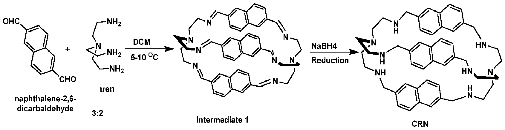 [0208] Synthesis of DHT. Scheme S4 shows the steps of DHT synthesis. 2,2'- ((oxybis(ethane-2,1-diyl))bis(oxy))bis(ethan-1-amine) (1.00 g, 5.20 mmol) was dissolved in dry acetonitrile (250 mL) at room temperature.1-iodo-2-(2-(2-(2-iodoethoxy)ethoxy)ethoxy)ethane (synthesized in the lab)(4.36 g, 10.5 mmol) was added into the reaction mixture, followed by addition of K2CO3 (15 g). The mixture was heated to reflux for 48 hours. After cooling to room temperature, excess of K2CO3 was filtered out, and the solvent was recovered under pressure in a rotavapor. The semi-solid crude material was recrystallized from Ethanol/THF (2:50) to obtain white powder (1.80 g, 58 %). [0209] 1H-NMR analysis is shown in Fig. 29, the results of which are: (CDCl3, 600 MHz, RT): δ = 2.6 (m, 12H), 3.57 (t, 12H), 3.65 (m, 24H) ppm.
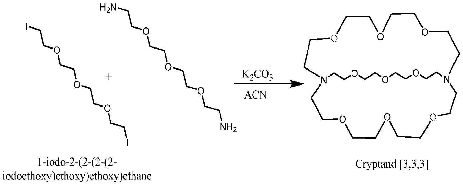 Scheme S4 The synthesis scheme of Cryptand [3.3.3]
Attorney Docket No. 11001-170WO1 [0210] Synthesis of 1-iodo-2-(2-(2-(2-iodoethoxy)ethoxy)ethoxy)ethane: Scheme S5 shows the steps of the synthesis. 1-chloro-2-(2-(2-(2-chloroethoxy)ethoxy)ethoxy)ethane (5.0 g, 21.6 mmol) was dissolved in acetone (250 mL), then sodium iodide, NaI, (6.0 g) was added and, the mixture was heated to reflux for 72 hours. After cooling to room temperature, excess of NaI was filtered out, and the solvent was recovered to obtain a pale yellow liquid as 1-iodo-2-(2-(2-(2- iodoethoxy)ethoxy)ethoxy)ethane (8.96g, 98% yield). The transformation of the dichloro compound into its diiodo counterpart was confirmed from HNMR (Fig. 30) and wet-silver nitrate test in the lab (Fig. 31). [0211] 1H-NMR analysis is shown in Fig. 30, the results of which are: (CDCl3, 600 MHz, RT): δ = 3.62-3.60 (t, 4H), 3.52 (s, 16H), 3.14-3.11 (t, 4H) ppm.
Scheme S4 The synthesis scheme of Cryptand [3.3.3]
Attorney Docket No. 11001-170WO1 [0210] Synthesis of 1-iodo-2-(2-(2-(2-iodoethoxy)ethoxy)ethoxy)ethane: Scheme S5 shows the steps of the synthesis. 1-chloro-2-(2-(2-(2-chloroethoxy)ethoxy)ethoxy)ethane (5.0 g, 21.6 mmol) was dissolved in acetone (250 mL), then sodium iodide, NaI, (6.0 g) was added and, the mixture was heated to reflux for 72 hours. After cooling to room temperature, excess of NaI was filtered out, and the solvent was recovered to obtain a pale yellow liquid as 1-iodo-2-(2-(2-(2- iodoethoxy)ethoxy)ethoxy)ethane (8.96g, 98% yield). The transformation of the dichloro compound into its diiodo counterpart was confirmed from HNMR (Fig. 30) and wet-silver nitrate test in the lab (Fig. 31). [0211] 1H-NMR analysis is shown in Fig. 30, the results of which are: (CDCl3, 600 MHz, RT): δ = 3.62-3.60 (t, 4H), 3.52 (s, 16H), 3.14-3.11 (t, 4H) ppm.
 ethoxy)ethoxy)ethane [0212] Synthesis of (CRB)Pb2Cl13(H3O) [0213] 42 mg (0.05 mmol) of the linker (CRB) was dissolved in a solution comprising of 8 mL of ethyl alcohol and 8 mL of 48% aqueous HBr was added dropwise while heating under constant magnetic stirring. To the hot colorless solution, 23 mg (0.1 mmol) of PbO was added, then heating was discontinued, and the sample was left to cool to room temperature. Colorless crystals deposited after 10 minutes, were collected by suction filtration, and dried under vacuum overnight. [0214] Fig.33 shows part of the crystal structure of (CRB)Pb2Cl13(H3O), viewing along the α- axis. Fig. 34 shows a comparison of the experimental PXRD pattern for the (CRB)Pb2Cl13(H3O) to the calculated one from the single crystal XRD studies. [0215] Synthesis of (CRT)(H3O)2Pb2Cl14 [0216] 30 mg (0.05 mmol) of the linker (CRT) was dissolved in a solution comprising of 2mL of ethyl alcohol and 2 mL of HCl was added dropwise while heating under constant
Attorney Docket No.11001-170WO1 magnetic stirring. To the hot colorless solution, 23 mg (0.1 mmol) of PbO were added, then heating was discontinued, and the sample was left to cool to room temperature. Colorless crystals were deposited after 10 minutes, were collected by suction filtration, and dried under vacuum overnight. [0217] Fig.35 shows part of the crystal structure of (CRT)(H3O)2Pb2Cl14, viewing along the c-axis. Fig.36 shows comparison of the experimental PXRD pattern for the (CRT)(H3O)2Pb2Cl14, to the calculated one from the single crystal XRD studies [0218] Synthesis of (CRT)(H3O)PbBr11 [0219] 30 mg (0.05 mmol) of the linker (CRT) was dissolved in a solution comprising 2mL of ethyl alcohol and 4 mL of 48% aqueous HBr was added dropwise while heating under constant magnetic stirring. To the hot colorless solution, 23 mg (0.1 mmol) of PbO was added, then heating was discontinued, and the sample was left to cool to room temperature. Colorless crystals deposited after 10 minutes, were collected by suction filtration, and dried under vacuum overnight. [0220] Fig.37 shows part of the crystal structure of (CRT)(H3O)PbBr11. Fig.38 shows Comparison of the experimental PXRD pattern for the (CRT)(H3O)PbBr11, to the calculated one from the single crystal XRD studies. [0221] Synthesis of (DHT)(K)(H3O)Pb3Br10 [0222] 233 mg (1 mmol) of PbO was dissolved in a solution comprising 1 mL of 48% aqueous HBr while heating under constant magnetic stirring. To the hot colorless solution, 338 mg (0.5 mmol) of DHT linker was addedm, the heating was discontinued, and the sample was left to cool to room temperature. Colorless crystals deposited after 10 minutes, were collected by suction filtration, and dried under vacuum overnight. [0223] Fig.39 shows a) part of the crystal structure of (DHT)(K)(H3O)Pb3Br10 across the b- axis, and b) the coordination environment of the K+ among the DHT ligand and the inorganic part of the structure. Fig.40 shows comparison of the experimental PXRD pattern for the (DHT)(K)(H3O)Pb3Br10, to the calculated one from the single crystal XRD studies. [0224] Synthesis of (DHS)Bi₂I₈: 95 mg (0.25 mmol) of DHS linker was dissolved in a solution consisting of 2 mL of 57 wt % HI and 0.5 mL of 50 wt % H₃PO₂, by heating under constant magnetic stirring. Then, 233 mg (0.5 mmol) of Bi₂O₃ was added to the hot colorless solution. Heating was discontinued and the sample was left to cool to RT directly. Dark
Attorney Docket No.11001-170WO1 orange crystals deposited after 10 min. They were collected by suction filtration and dried under vacuum overnight Yield = 64%, based on Bi. [0225] Fig.14 shows comparison of the PXRD patterns for the as-made (DHS)Bi2I8 crystals and water-treated (DHS)Bi2I8 (top), and an enlargement of highlighted area (bottom). [0226] Synthesis of (DHS)SnCl4: 35 mg (0.1 mmol) of SnCl4 were dissolved in a solution consisting of 1 mL of Hydrochloric Acid 22 BE, Technical Grade, by heating under constant magnetic stirring. Then 5 mg (0.013 mmol) of DHS linker were added to the hot colorless solution. Heating was discontinued and the sample was left to cool to RT directly. Crystals deposited after 10 min. They were collected by suction filtration and dried under vacuum overnight. [0227] Fig.41 shows part of the crystal structure of (DHS)SnCl4. Fig.42 shows comparison of the PXRD patterns for the as-made (DHS)SnCl4 crystals to the calculated pattern from the solved single-crystal structure. [0228] Synthesis of (DHS)SnBr4: 44 mg (0.1 mmol) of SnBr4 were dissolved in a solution consisting of 1 mL of Ethyl alcohol, Pure 200 proof, ACS reagent, ≥99.5%, by heating under constant magnetic stirring. 5 mg (0.013 mmol) of DHS linker were dissolved in a solution consisting of 1 mL 48% aqueous HBr , by heating under constant magnetic stirring in a different vial. Then DHS linker solution was added to SnBr4 solution. Crystals deposited immediately after combining solutions. They were collected by suction filtration and dried under vacuum overnight. [0229] Fig.43 shows part of the crystal structure of (DHS)SnBr4. Fig.44 shows comparison of the PXRD patterns for the as-made (DHS)SnBr4 crystals to the calculated pattern from the solved single-crystal structure. [0230] Synthesis of (DHS)2Pb5Cl14: 40 mg (0.1 mmol) of DHS linker were dissolved in a solution consisting of 0.5 mL of Hydrochloric Acid 22 BE, Technical Grade, by heating under constant magnetic stirring. Then 44 mg (0.2 mmol) of PbO were added to the hot colorless solution. Heating was discontinued and the sample was left to cool to RT directly. Crystals deposited after 10 min. They were collected by suction filtration and dried under vacuum overnight. [0231] Fig.45 shows part of the crystal structure of (DHS)2Pb5Cl4. Fig.46 shows comparison of the PXRD patterns for the as-made (DHS)2Pb5Cl4 crystals to the calculated pattern from the solved single-crystal structure.
Attorney Docket No.11001-170WO1 [0232] Synthesis of (DHS)Sb2Br8: 19 mg (0.05 mmol) of DHS linker were dissolved in a solution consisting of 0.5 mL of 48% aqueous HBr, by heating under constant magnetic stirring. Then 30 mg (0.1 mmol) of Sb2O3 were added to the hot colorless solution. Heating was discontinued and the sample was left to cool to RT directly. Crystals deposited after 10 min. They were collected by suction filtration and dried under vacuum overnight. [0233] Fig.47 shows part of the crystal structure of (DHS)Sb2Br8. Fig.48 shows comparison of the PXRD patterns for the as-made (DHS)2Pb5Cl4 crystals to the calculated pattern from the solved single-crystal structure. [0234] Synthesis of (DHS)2SbBr7: 19 mg (0.05 mmol) of DHS linker were dissolved in a solution consisting of 0.75 mL of 57% aqueous HI, by heating under constant magnetic stirring. Then 30 mg (0.1 mmol) of Sb2O3 were added to the hot colorless solution. Heating was discontinued and the sample was left to cool to RT directly. Orange crystals deposited after 10 min. They were collected by suction filtration and dried under vacuum overnight. [0235] Fig.49 shows part of the crystal structure of (DHS)2SbBr7. Fig.50 shows comparison of the PXRD patterns for the as-made (DHS)2SbBr7 crystals to the calculated pattern from the solved single-crystal structure. [0236] Synthesis of (DHS)Sb2Cl8: 20 mg (0.069 mmol) of Sb2O3 were dissolved in a solution consisting of 0.75 mL of Hydrochloric Acid 22 BE, Technical Grade, by heating under constant magnetic stirring. Then 10 mg (0.027 mmol) of DHS linker were added to the hot colorless solution. Heating was discontinued and the sample was left to cool to RT directly. White crystals deposited after 10 min. They were collected by suction filtration and dried under vacuum overnight. [0237] Fig.51 shows part of the crystal structure of (DHS)Sb2Cl8. The reticular expansion of linker molecules, CRT, CRN, and CRB are shown in Fig. 32 with the increasing channel size measurement provided. The DHT linker is shown for comparison.
ethoxy)ethoxy)ethane [0212] Synthesis of (CRB)Pb2Cl13(H3O) [0213] 42 mg (0.05 mmol) of the linker (CRB) was dissolved in a solution comprising of 8 mL of ethyl alcohol and 8 mL of 48% aqueous HBr was added dropwise while heating under constant magnetic stirring. To the hot colorless solution, 23 mg (0.1 mmol) of PbO was added, then heating was discontinued, and the sample was left to cool to room temperature. Colorless crystals deposited after 10 minutes, were collected by suction filtration, and dried under vacuum overnight. [0214] Fig.33 shows part of the crystal structure of (CRB)Pb2Cl13(H3O), viewing along the α- axis. Fig. 34 shows a comparison of the experimental PXRD pattern for the (CRB)Pb2Cl13(H3O) to the calculated one from the single crystal XRD studies. [0215] Synthesis of (CRT)(H3O)2Pb2Cl14 [0216] 30 mg (0.05 mmol) of the linker (CRT) was dissolved in a solution comprising of 2mL of ethyl alcohol and 2 mL of HCl was added dropwise while heating under constant
Attorney Docket No.11001-170WO1 magnetic stirring. To the hot colorless solution, 23 mg (0.1 mmol) of PbO were added, then heating was discontinued, and the sample was left to cool to room temperature. Colorless crystals were deposited after 10 minutes, were collected by suction filtration, and dried under vacuum overnight. [0217] Fig.35 shows part of the crystal structure of (CRT)(H3O)2Pb2Cl14, viewing along the c-axis. Fig.36 shows comparison of the experimental PXRD pattern for the (CRT)(H3O)2Pb2Cl14, to the calculated one from the single crystal XRD studies [0218] Synthesis of (CRT)(H3O)PbBr11 [0219] 30 mg (0.05 mmol) of the linker (CRT) was dissolved in a solution comprising 2mL of ethyl alcohol and 4 mL of 48% aqueous HBr was added dropwise while heating under constant magnetic stirring. To the hot colorless solution, 23 mg (0.1 mmol) of PbO was added, then heating was discontinued, and the sample was left to cool to room temperature. Colorless crystals deposited after 10 minutes, were collected by suction filtration, and dried under vacuum overnight. [0220] Fig.37 shows part of the crystal structure of (CRT)(H3O)PbBr11. Fig.38 shows Comparison of the experimental PXRD pattern for the (CRT)(H3O)PbBr11, to the calculated one from the single crystal XRD studies. [0221] Synthesis of (DHT)(K)(H3O)Pb3Br10 [0222] 233 mg (1 mmol) of PbO was dissolved in a solution comprising 1 mL of 48% aqueous HBr while heating under constant magnetic stirring. To the hot colorless solution, 338 mg (0.5 mmol) of DHT linker was addedm, the heating was discontinued, and the sample was left to cool to room temperature. Colorless crystals deposited after 10 minutes, were collected by suction filtration, and dried under vacuum overnight. [0223] Fig.39 shows a) part of the crystal structure of (DHT)(K)(H3O)Pb3Br10 across the b- axis, and b) the coordination environment of the K+ among the DHT ligand and the inorganic part of the structure. Fig.40 shows comparison of the experimental PXRD pattern for the (DHT)(K)(H3O)Pb3Br10, to the calculated one from the single crystal XRD studies. [0224] Synthesis of (DHS)Bi₂I₈: 95 mg (0.25 mmol) of DHS linker was dissolved in a solution consisting of 2 mL of 57 wt % HI and 0.5 mL of 50 wt % H₃PO₂, by heating under constant magnetic stirring. Then, 233 mg (0.5 mmol) of Bi₂O₃ was added to the hot colorless solution. Heating was discontinued and the sample was left to cool to RT directly. Dark
Attorney Docket No.11001-170WO1 orange crystals deposited after 10 min. They were collected by suction filtration and dried under vacuum overnight Yield = 64%, based on Bi. [0225] Fig.14 shows comparison of the PXRD patterns for the as-made (DHS)Bi2I8 crystals and water-treated (DHS)Bi2I8 (top), and an enlargement of highlighted area (bottom). [0226] Synthesis of (DHS)SnCl4: 35 mg (0.1 mmol) of SnCl4 were dissolved in a solution consisting of 1 mL of Hydrochloric Acid 22 BE, Technical Grade, by heating under constant magnetic stirring. Then 5 mg (0.013 mmol) of DHS linker were added to the hot colorless solution. Heating was discontinued and the sample was left to cool to RT directly. Crystals deposited after 10 min. They were collected by suction filtration and dried under vacuum overnight. [0227] Fig.41 shows part of the crystal structure of (DHS)SnCl4. Fig.42 shows comparison of the PXRD patterns for the as-made (DHS)SnCl4 crystals to the calculated pattern from the solved single-crystal structure. [0228] Synthesis of (DHS)SnBr4: 44 mg (0.1 mmol) of SnBr4 were dissolved in a solution consisting of 1 mL of Ethyl alcohol, Pure 200 proof, ACS reagent, ≥99.5%, by heating under constant magnetic stirring. 5 mg (0.013 mmol) of DHS linker were dissolved in a solution consisting of 1 mL 48% aqueous HBr , by heating under constant magnetic stirring in a different vial. Then DHS linker solution was added to SnBr4 solution. Crystals deposited immediately after combining solutions. They were collected by suction filtration and dried under vacuum overnight. [0229] Fig.43 shows part of the crystal structure of (DHS)SnBr4. Fig.44 shows comparison of the PXRD patterns for the as-made (DHS)SnBr4 crystals to the calculated pattern from the solved single-crystal structure. [0230] Synthesis of (DHS)2Pb5Cl14: 40 mg (0.1 mmol) of DHS linker were dissolved in a solution consisting of 0.5 mL of Hydrochloric Acid 22 BE, Technical Grade, by heating under constant magnetic stirring. Then 44 mg (0.2 mmol) of PbO were added to the hot colorless solution. Heating was discontinued and the sample was left to cool to RT directly. Crystals deposited after 10 min. They were collected by suction filtration and dried under vacuum overnight. [0231] Fig.45 shows part of the crystal structure of (DHS)2Pb5Cl4. Fig.46 shows comparison of the PXRD patterns for the as-made (DHS)2Pb5Cl4 crystals to the calculated pattern from the solved single-crystal structure.
Attorney Docket No.11001-170WO1 [0232] Synthesis of (DHS)Sb2Br8: 19 mg (0.05 mmol) of DHS linker were dissolved in a solution consisting of 0.5 mL of 48% aqueous HBr, by heating under constant magnetic stirring. Then 30 mg (0.1 mmol) of Sb2O3 were added to the hot colorless solution. Heating was discontinued and the sample was left to cool to RT directly. Crystals deposited after 10 min. They were collected by suction filtration and dried under vacuum overnight. [0233] Fig.47 shows part of the crystal structure of (DHS)Sb2Br8. Fig.48 shows comparison of the PXRD patterns for the as-made (DHS)2Pb5Cl4 crystals to the calculated pattern from the solved single-crystal structure. [0234] Synthesis of (DHS)2SbBr7: 19 mg (0.05 mmol) of DHS linker were dissolved in a solution consisting of 0.75 mL of 57% aqueous HI, by heating under constant magnetic stirring. Then 30 mg (0.1 mmol) of Sb2O3 were added to the hot colorless solution. Heating was discontinued and the sample was left to cool to RT directly. Orange crystals deposited after 10 min. They were collected by suction filtration and dried under vacuum overnight. [0235] Fig.49 shows part of the crystal structure of (DHS)2SbBr7. Fig.50 shows comparison of the PXRD patterns for the as-made (DHS)2SbBr7 crystals to the calculated pattern from the solved single-crystal structure. [0236] Synthesis of (DHS)Sb2Cl8: 20 mg (0.069 mmol) of Sb2O3 were dissolved in a solution consisting of 0.75 mL of Hydrochloric Acid 22 BE, Technical Grade, by heating under constant magnetic stirring. Then 10 mg (0.027 mmol) of DHS linker were added to the hot colorless solution. Heating was discontinued and the sample was left to cool to RT directly. White crystals deposited after 10 min. They were collected by suction filtration and dried under vacuum overnight. [0237] Fig.51 shows part of the crystal structure of (DHS)Sb2Cl8. The reticular expansion of linker molecules, CRT, CRN, and CRB are shown in Fig. 32 with the increasing channel size measurement provided. The DHT linker is shown for comparison.
Claims
Attorney Docket No.11001-170WO1 CLAIMS What is claimed is: 1. A porous semiconductor material comprising: a metal halide; and an organic linker molecule, wherein the organic linker molecule comprises a cavity. 2. The porous semiconductor material of claim 1, wherein the metal halide is a perovskite or perovskitoid type structure. 3. The porous semiconductor material of claim 1, wherein the organic linker molecule comprises a cationic charge. 4. The porous semiconductor material of claim 1, wherein the porous semiconductor material retains its crystallographic structure in water for 6 months or more. 5. The porous semiconductor material of claim 1, wherein the cavity of the organic linker molecule has an internal diameter in a range of 2 angstroms to 15.3 angstroms. 6. The porous semiconductor material of claim 5, wherein the organic linker molecule selectively traps water, Li+, K+, Na+, Mg2+, Al3+, or deuterated water. 7. The porous semiconductor material of claim 1, wherein a metal of the metal halide is chosen from In, Cu, Au, Al, Ga, Ge, Sn, Pb, Sb, Bi, and any combination thereof. 8. The porous semiconductor material of claim 1, wherein a halide of the metal halide is chosen from F-, Cl-, Br-, I-, or any combination thereof. 9. The porous semiconductor material of claim 1, wherein the organic linker molecule comprises one or more of an amine functionalized cucurbituril, an amine functionalized crown ether, a [2.2.2] cryptand, an expanded cryptand analog comprising aliphatic substituent chains containing carbon, nitrogen, or oxygen atoms, an expanded
Attorney Docket No.11001-170WO1 phosphonium cryptand, (1,4,7,10,13,16,19,22-octaoxacyclotetracosan-2-yl)methanamine, a [2.2.1] cryptand, monofunctionalized crown ether comprising one or two of an aliphatic or aromatic substituent containing ammonium or phosphonium cations, or monofunctionalized crown ether comprising two ring substituents of aliphatic chains of carbon and oxygen atoms and at least two side groups comprising aliphatic or aromatic chains functionalized with ammonium or phosphonium groups. 10. The porous semiconductor material of claim 9, wherein the organic linker molecule is chosen from DHS, DHT, CRT, CRN, and CRB. 11. The porous semiconductor material of claim 1 further comprising water. 12. The porous semiconductor material of any of the previous claims, wherein the semiconductor material comprises (CRB)Pb2Cl13(H3O), (CRT)(H3O)2Pb2Cl14, (CRT)(H3O)2Pb2Cl14, (CRT)(H3O)PbBr11, (DHT)(K)(H3O)Pb3Br10, (DHS)2Pb5Br14, (DHS)2Pb5Cl14, (DHS)Sb2Br7, (DHS)SnCl4, (DHS)SnBr4, (DHS)2SbBr7, (DHS)Sb2Cl8, (DHS)Bi2I8, or a combination thereof. 13. A method to synthesize a porous semiconductor material, the method comprising: providing a metal halide in a solution; adding an organic linker molecule to the solution; forming a precipitate; and separating the precipitate, wherein the precipitate is the porous semiconductor material. 14. The method of claim 13, wherein the metal halide comprises one or more of In, Cu, Au, Al, Ga, Ge, Sn, Pb, Sb, and Bi, and comprises one or more of F-, Cl-, Br-, and I-. 15. The method of claim 13, wherein the organic linker molecule comprises one or more of an amine functionalized cucurbituril, an amine functionalized crown ether, a [2.2.2] cryptand, an expanded cryptand analog comprising aliphatic substituent chains containing carbon, nitrogen, or oxygen atoms, an expanded phosphonium cryptand,
Attorney Docket No.11001-170WO1 (1,4,7,10,13,16,19,22-octaoxacyclotetracosan-2-yl)methanamine, a [2.2.1] cryptand, monofunctionalized crown ether comprising one or two of an aliphatic or aromatic substituent containing ammonium or phosphonium cations, or monofunctionalized crown ether comprising two ring substituents of apliphatic changes of carbon and oxygen atoms and at least two side groups comprising aliphatic or aromatic chains functionalized with ammonium or phosphonium groups. 16. The method of claim 15, wherein the organic linker molecule is chosen from DHS, DHT, CRT, CRN, and CRB. 17. The method of claim 13, wherein the porous semiconductor material comprises a perovskite, perovskitoid, or metal halide type material. 18. The method of claim 13, further comprising adding heat to the solution. 19. The method of claim 18, further comprising removing the source of heat from the solution after the organic linker molecule is added. 20. The method of claim 13, further comprising synthesizing the organic linker molecule. 21. The method of claim 13, wherein the solution comprises an acid. 22. A gas sorption material comprising the porous semiconductor material of claim 1. 23. A material having antibacterial activity comprising the porous semiconductor material of claim 1. 24. A photocatalytic material comprising the porous semiconductor material of claim 1.
Applications Claiming Priority (4)
| Application Number | Priority Date | Filing Date | Title |
|---|---|---|---|
| US202263381859P | 2022-11-01 | 2022-11-01 | |
| US63/381,859 | 2022-11-01 | ||
| US202363490924P | 2023-03-17 | 2023-03-17 | |
| US63/490,924 | 2023-03-17 |
Publications (2)
| Publication Number | Publication Date |
|---|---|
| WO2024097789A2 true WO2024097789A2 (en) | 2024-05-10 |
| WO2024097789A3 WO2024097789A3 (en) | 2024-06-13 |
Family
ID=90931585
Family Applications (1)
| Application Number | Title | Priority Date | Filing Date |
|---|---|---|---|
| PCT/US2023/078399 Ceased WO2024097789A2 (en) | 2022-11-01 | 2023-11-01 | Porous hybrid metal halide semiconductors |
Country Status (1)
| Country | Link |
|---|---|
| WO (1) | WO2024097789A2 (en) |
Cited By (1)
| Publication number | Priority date | Publication date | Assignee | Title |
|---|---|---|---|---|
| CN120325299A (en) * | 2025-06-16 | 2025-07-18 | 江西师范大学 | CoS/CuCo2S4 photocatalyst and its preparation method and application |
Family Cites Families (2)
| Publication number | Priority date | Publication date | Assignee | Title |
|---|---|---|---|---|
| US4777023A (en) * | 1986-02-18 | 1988-10-11 | Solarex Corporation | Preparation of silicon and germanium hydrides containing two different group 4A atoms |
| AU2003272969A1 (en) * | 2002-10-10 | 2004-05-04 | Kansai Paint Co., Ltd. | Method for forming semiconductor film and use of semiconductor film |
-
2023
- 2023-11-01 WO PCT/US2023/078399 patent/WO2024097789A2/en not_active Ceased
Cited By (1)
| Publication number | Priority date | Publication date | Assignee | Title |
|---|---|---|---|---|
| CN120325299A (en) * | 2025-06-16 | 2025-07-18 | 江西师范大学 | CoS/CuCo2S4 photocatalyst and its preparation method and application |
Also Published As
| Publication number | Publication date |
|---|---|
| WO2024097789A3 (en) | 2024-06-13 |
Similar Documents
| Publication | Publication Date | Title |
|---|---|---|
| Modrow et al. | The first porous MOF with photoswitchable linker molecules | |
| Nassar et al. | Synthesis, characterization, and biological activity of some novel Schiff bases and their Co (II) and Ni (II) complexes: a new route for Co3O4 and NiO nanoparticles for photocatalytic degradation of methylene blue dye | |
| Artem'ev et al. | Alkyl-dependent self-assembly of the first red-emitting zwitterionic {Cu 4 I 6} clusters from [alkyl-P (2-Py) 3]+ salts and CuI: when size matters | |
| Marques et al. | New photo/electroluminescent europium (III) β-diketonate complex containing ap, p′-disubstituted bipyridine ligand: Synthesis, solid state characterization, theoretical and experimental spectroscopic studies | |
| Yin et al. | Role of molar-ratio, temperature and solvent on the Zn/Cd 1, 2, 4-triazolate system with novel topological architectures | |
| Wang et al. | A stable europium metal–organic framework as a dual-functional luminescent sensor for quantitatively detecting temperature and humidity | |
| Piccinelli et al. | Structural, optical and sensing properties of novel Eu (III) complexes with furan-and pyridine-based ligands | |
| Xue et al. | Multicolour-and high-colour-contrast switching in response to force and acid vapour by introducing an asymmetric D–π–A–π–D structure | |
| Petryk et al. | Chiral, triformylphenol-derived salen-type [4+ 6] organic cages | |
| Refat et al. | Utility of positron annihilation lifetime technique for the assessment of spectroscopic data of some charge-transfer complexes derived from N-(1-Naphthyl) ethylenediamine dihydrochloride | |
| Adam et al. | Spectral, thermal, XRD and SEM studies of charge-transfer complexation of hexamethylenediamine and three types of acceptors: π-, σ-and vacant orbital acceptors that include quinol, picric acid, bromine, iodine, SnCl4 and ZnCl2 acceptors | |
| US20140287514A1 (en) | Luminescent microporous material for detection and discrimination of low-levels of common gases and vapors | |
| Huisman et al. | Zero-dimensional hybrid organic–inorganic lead halides and their post-synthesis reversible transformation into three-dimensional perovskites | |
| Feng et al. | [AEPH 2][GeSb 2 S 6]· CH 3 OH: a thiogermanate–thioantimonate featuring an infinite ribbon-like structure with an unusual {GeSb 3 S 11} unit and exhibiting the ability of photocatalytic degradation of organic dye | |
| Zhang et al. | Synthesis and fluxional behaviour of novel chloroborole dimers | |
| Jackson et al. | Clathrate directed assembly of tetrapyridyl-tetraphenylethylene metal–organic frameworks | |
| Kotov et al. | A hybrid halobismuthate light-harvesting material with an optical band gap of 1.70 eV | |
| WO2024097789A2 (en) | Porous hybrid metal halide semiconductors | |
| Neupane et al. | Synthesis, spectroscopic, crystal structure, thermal and optical studies of a novel proton transfer complex: 2-Methyl-8-hydroxyquinoliniumpicrate | |
| Hyodo et al. | Cycloalkanes and cycloalkenes in dispersive force oriented inclusion crystals by a functionalized acyclic host molecule | |
| Krüger et al. | Effect of partial linker fluorination and linker extension on structure and properties of the Al-MOF CAU-10 | |
| Hay et al. | Modulating the electronic properties of divalent lanthanoid complexes with subtle ligand tuning | |
| Lennox et al. | Simplifying and expanding the scope of boron imidazolate framework (BIF) synthesis using mechanochemistry | |
| Thakker et al. | Synthetic control of the cis/trans geometry of [M (cyclam)(CCR) 2] OTf complexes and photophysics of cis-[Cr (cyclam)(CCCF3) 2] OTf and cis-[Rh (cyclam)(CCCF3) 2] OTf | |
| Pavelek et al. | Dioxouranium complexes with pentadentate s-triazine Schiff base ligands: Synthesis, crystal structure and optical properties |
Legal Events
| Date | Code | Title | Description |
|---|---|---|---|
| 121 | Ep: the epo has been informed by wipo that ep was designated in this application |
Ref document number: 23886952 Country of ref document: EP Kind code of ref document: A2 |
|
| NENP | Non-entry into the national phase |
Ref country code: DE |
|
| 122 | Ep: pct application non-entry in european phase |
Ref document number: 23886952 Country of ref document: EP Kind code of ref document: A2 |