WO2024095784A1 - 流体圧シリンダユニット - Google Patents
流体圧シリンダユニット Download PDFInfo
- Publication number
- WO2024095784A1 WO2024095784A1 PCT/JP2023/037834 JP2023037834W WO2024095784A1 WO 2024095784 A1 WO2024095784 A1 WO 2024095784A1 JP 2023037834 W JP2023037834 W JP 2023037834W WO 2024095784 A1 WO2024095784 A1 WO 2024095784A1
- Authority
- WO
- WIPO (PCT)
- Prior art keywords
- chamber
- accumulator
- passage
- fluid pressure
- gas
- Prior art date
- Legal status (The legal status is an assumption and is not a legal conclusion. Google has not performed a legal analysis and makes no representation as to the accuracy of the status listed.)
- Ceased
Links
Images


Classifications
-
- F—MECHANICAL ENGINEERING; LIGHTING; HEATING; WEAPONS; BLASTING
- F15—FLUID-PRESSURE ACTUATORS; HYDRAULICS OR PNEUMATICS IN GENERAL
- F15B—SYSTEMS ACTING BY MEANS OF FLUIDS IN GENERAL; FLUID-PRESSURE ACTUATORS, e.g. SERVOMOTORS; DETAILS OF FLUID-PRESSURE SYSTEMS, NOT OTHERWISE PROVIDED FOR
- F15B1/00—Installations or systems with accumulators; Supply reservoir or sump assemblies
- F15B1/02—Installations or systems with accumulators
-
- F—MECHANICAL ENGINEERING; LIGHTING; HEATING; WEAPONS; BLASTING
- F15—FLUID-PRESSURE ACTUATORS; HYDRAULICS OR PNEUMATICS IN GENERAL
- F15B—SYSTEMS ACTING BY MEANS OF FLUIDS IN GENERAL; FLUID-PRESSURE ACTUATORS, e.g. SERVOMOTORS; DETAILS OF FLUID-PRESSURE SYSTEMS, NOT OTHERWISE PROVIDED FOR
- F15B11/00—Servomotor systems without provision for follow-up action; Circuits therefor
- F15B11/06—Servomotor systems without provision for follow-up action; Circuits therefor involving features specific to the use of a compressible medium, e.g. air, steam
- F15B11/072—Combined pneumatic-hydraulic systems
-
- F—MECHANICAL ENGINEERING; LIGHTING; HEATING; WEAPONS; BLASTING
- F15—FLUID-PRESSURE ACTUATORS; HYDRAULICS OR PNEUMATICS IN GENERAL
- F15B—SYSTEMS ACTING BY MEANS OF FLUIDS IN GENERAL; FLUID-PRESSURE ACTUATORS, e.g. SERVOMOTORS; DETAILS OF FLUID-PRESSURE SYSTEMS, NOT OTHERWISE PROVIDED FOR
- F15B15/00—Fluid-actuated devices for displacing a member from one position to another; Gearing associated therewith
- F15B15/08—Characterised by the construction of the motor unit
- F15B15/14—Characterised by the construction of the motor unit of the straight-cylinder type
Definitions
- the present invention relates to a fluid pressure cylinder unit.
- JP2016-176566A discloses a fluid pressure cylinder having a cylindrical cylinder tube with a bottom that has an opening at one end, a rod that is inserted into the cylinder tube, and a piston that is connected to the tip of the rod and divides the inside of the cylinder tube into a rod side chamber filled with gas and a bottom side chamber to which hydraulic fluid is supplied and discharged.
- the rod side chamber is filled with gas, and hydraulic oil is supplied and discharged to the bottom side chamber.
- the fluid pressure cylinder extends due to hydraulic oil pressure guided to the bottom side chamber from a hydraulic source.
- the purpose of the present invention is to effectively utilize the high-pressure gas discharged from the first chamber of a fluid pressure cylinder.
- a fluid pressure cylinder unit comprising: a fluid pressure cylinder having a cylinder tube; a piston rod reciprocally disposed within the cylinder tube and dividing the interior of the cylinder tube into a first chamber and a second chamber; an accumulator having an air chamber that can be filled with gas and a liquid chamber that can be filled with liquid; and a first passageway that connects the first chamber to the air chamber of the accumulator, the first chamber being filled with gas and the piston rod reciprocating as hydraulic fluid is supplied to and discharged from the second chamber, and the first passageway being provided with a valve that is capable of only allowing the flow of gas from the first chamber to the air chamber of the accumulator.
- FIG. 1 is a circuit diagram of a fluid pressure cylinder unit according to an embodiment of the present invention.
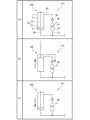
- FIG. 2 is a diagram showing the operation of the fluid pressure cylinder unit according to the embodiment of the present invention and the charging of gas into the accumulator.
- FIG. 3 is a circuit diagram of a fluid pressure cylinder unit according to a first modified example of the embodiment of the present invention.
- FIG. 4 is a circuit diagram of a fluid pressure cylinder unit according to a second modified example of the embodiment of the present invention.
- FIG. 5 is a circuit diagram of a fluid pressure cylinder unit according to a third modified example of the embodiment of the present invention.
- the fluid pressure cylinder unit 101 includes a fluid pressure cylinder and an accumulator 40 connected to the fluid pressure cylinder.
- the fluid pressure cylinder is a lift cylinder 100 that raises and lowers the forks of a forklift.
- the lift cylinder 100 is a single-acting hydraulic cylinder. As shown in FIG. 1, the lift cylinder 100 has a cylinder tube 1, a piston rod 10 that is reciprocally disposed within the cylinder tube 1 and divides the cylinder tube 1 into a rod side chamber 2 as a first chamber and a counter-rod side chamber 3 as a second chamber, a first passage 30 connected to the rod side chamber 2, and a main passage 20 connected to the counter-rod side chamber 3.
- the piston rod 10 has a piston 11 that is slidably arranged along the inner circumferential surface of the cylinder tube 1, and a rod 12 that has one end connected to the piston 11 and the other end extending outside the cylinder tube 1 and reciprocating.
- the rod side chamber 2 is filled with a gas such as air.
- “filling” includes actively introducing gas into the rod side chamber 2 using a cylinder or the like, and mixing of gas into the rod side chamber 2 when assembling the lift cylinder 100.
- Gas is discharged from the rod side chamber 2 through the first passage 30. Hydraulic oil is supplied and discharged as a hydraulic fluid to the anti-rod side chamber 3 through the main passage 20.
- a liquid other than hydraulic oil, such as water, may be used as the hydraulic fluid.
- a switching valve (not shown) is provided in the main passage 20, and by switching the switching valve, the main passage 20 is connected to a pump (not shown) or a tank (not shown).
- the lift cylinder 100 hydraulic oil is supplied to and discharged from the anti-rod side chamber 3 through the main passage 20, causing the piston rod 10 to reciprocate.
- the piston rod 10 moves upward (upward in FIG. 1), the lift cylinder 100 extends, and the fork and the luggage placed on the fork rise.
- the piston rod 10 moves downward (downward in FIG. 1), the lift cylinder 100 contracts, and the fork and luggage descend.
- the accumulator 40 has an air chamber 41 that can be filled with gas and a liquid chamber 42 that can be filled with liquid.
- the accumulator 40 is provided separately from the lift cylinder 100.
- the air chamber 41 and the liquid chamber 42 may be partitioned by a partition member such as a free piston or a bladder.
- the air chamber 41 is connected to the first passage 30, and the liquid chamber 42 is connected to a branch passage 21 that branches off from the main passage 20. In this way, the rod side chamber 2 and the air chamber 41 communicate through the first passage 30, and the anti-rod side chamber 3 and the liquid chamber 42 communicate through the main passage 20 and the branch passage 21.
- the first passage 30 is provided with a check valve 50 as a valve that can only allow the flow of gas from the rod side chamber 2 to the air chamber 41 of the accumulator 40.
- a check valve 50 instead of the check valve 50, an electromagnetic valve, a manual valve, or the like may be provided.
- the anti-rod side chamber 3 and the liquid chamber 42 may also communicate through a passage provided in parallel with the main passage 20.
- the fluid pressure cylinder unit 101 of this embodiment is assembled by connecting the lift cylinder 100 and the accumulator 40 under atmospheric pressure. Before the lift cylinder 100 and the accumulator 40 are connected, the air chamber 41 of the accumulator 40 is at atmospheric pressure and is not filled with high-pressure gas. The air chamber 41 of the accumulator 40 is filled with high-pressure gas by the initial operation of the lift cylinder 100 after the lift cylinder 100 and the accumulator 40 are connected.
- Figures 2(a)-(c) show the initial operation of the lift cylinder 100, with Figure 2(a) showing the state before the initial operation of the lift cylinder 100 (in other words, immediately after the lift cylinder 100 and the accumulator 40 are connected).
- the lift cylinder 100 is in a fully contracted state due to the weight of the piston rod 10.
- the rod side chamber 2 and the air chamber 41 of the accumulator 40 are at atmospheric pressure, and the air chamber 41 is not filled with high-pressure gas.
- the initial operation of the lift cylinder 100 is performed by supplying hydraulic oil from the hydraulic power source through the main passage 20 to the anti-rod side chamber 3 and extending the lift cylinder 100 (specifically, to its full extension), as shown in FIG. 2(b).
- This causes the gas in the rod side chamber 2 to be pressurized, and as shown by the arrow on the right side of FIG. 2(b), it is guided to the air chamber 41 of the accumulator 40 through the first passage 30 and the check valve 50.
- the air chamber 41 is then filled with high-pressure gas until the pressure in the air chamber 41 reaches the set pressure.
- FIG. 2(a)-(c) may be performed before or after the hydraulic cylinder unit 101 is mounted on the forklift. In addition, the operations in FIG. 2(a)-(c) may be performed during an operation test of the lift cylinder 100 or when bleeding air from the anti-rod side chamber 3. Also, if a solenoid valve, manual valve, etc. is provided instead of the check valve 50, it is sufficient that the rod side chamber 2 and the air chamber 41 of the accumulator 40 communicate through the first passage 30 when the lift cylinder 100 is extended, and the communication between the rod side chamber 2 and the air chamber 41 of the accumulator 40 is blocked when the lift cylinder 100 is contracted. Even in this configuration, the solenoid valve, manual valve, etc. can only allow the flow of gas from the rod side chamber 2 to the air chamber 41 of the accumulator 40.
- the pressure in the rod side chamber 2 is lower than the pressure in the air chamber 41 of the accumulator 40 until the lift cylinder 100 reaches its fully extended state, but the pressure in the air chamber 41 of the accumulator 40 is maintained by the check valve 50. Furthermore, when the lift cylinder 100 reaches its fully extended state, the pressure in the rod side chamber 2 becomes the same as the state shown in Figure 2 (b) and is equal to the pressure in the air chamber 41 of the accumulator 40. Thus, in normal operation of the lift cylinder 100, the gas in the rod side chamber 2 is not led to the air chamber 41 of the accumulator 40.
- the gas in the rod side chamber 2 is pressurized and filled into the air chamber 41 of the accumulator 40 only when the lift cylinder 100 is extended for the first time (specifically, fully extended).
- the air chamber 41 of the accumulator 40 is filled with high-pressure gas only when the lift cylinder 100 is initially operated, the air chamber 41 is not filled with high-pressure gas before the lift cylinder 100 is operated. Therefore, the accumulator 40 can be handled safely and easily. Furthermore, the accumulator 40 can be transported safely and easily. Furthermore, since the air chamber 41 of the accumulator 40 is filled with pressurized gas from the rod side chamber 2, there is no need to use a gas cylinder or the like to fill the air chamber 41 with high-pressure gas. Therefore, compared to the case where a gas cylinder or the like is used, the accumulator 40 can be handled safely and easily, and the manufacturing costs are reduced.
- the anti-rod side chamber 3 and the fluid chamber 42 of the accumulator 40 are connected through the main passage 20 and the branch passage 21, so that fluctuations in pressure within the main passage 20 and the anti-rod side chamber 3 are absorbed by the accumulator 40. Therefore, even if an impact from the road surface acts on the lift cylinder 100 while transporting luggage using a forklift, the vibration of the luggage can be absorbed by the accumulator 40. This makes it possible to prevent the luggage from collapsing during transportation.
- the gas filled in the rod side chamber 2 is pressurized and guided through the first passage 30 and the check valve 50 to the air chamber 41 of the accumulator 40. This allows the high-pressure gas discharged from the rod side chamber 2 to be effectively used as the gas filled in the air chamber 41 of the accumulator 40.
- the counter-rod side chamber 3 and the liquid chamber 42 of the accumulator 40 are connected by the main passage 20. Therefore, the vibration of the object driven by the lift cylinder 100, such as luggage, can be absorbed by the accumulator 40.
- the fluid pressure cylinder unit 101 includes the first passage 30 that communicates the rod side chamber 2 and the air chamber 41 of the accumulator 40.
- the fluid pressure cylinder unit 201 according to the first modification includes the second passage 31 that is connected between the rod side chamber 2 and the check valve 50 in the first passage 30 and communicates with the atmosphere.
- the second passage 31 communicates with the atmosphere through the filter 60.
- the second passage 31 is provided with a check valve 51 that only allows gas to flow from the atmosphere to the first passage 30. Therefore, when the pressure in the rod side chamber 2 and the first passage 30 drops (specifically, drops below atmospheric pressure) when the lift cylinder 100 contracts, gas is supplied to the rod side chamber 2 and the first passage 30 through the filter 60, the second passage 31, and the check valve 51. This allows the gas in the rod side chamber 2 to be repeatedly charged into the air chamber 41 of the accumulator 40 every time the lift cylinder 100 extends. This prevents the pressure in the air chamber 41 from dropping.
- the fluid pressure cylinder unit 201 includes a third passage 33 connected between the rod side chamber 2 and the check valve 50 in the first passage 30.
- the third passage 33 is connected to the atmosphere through a silencer 61.
- the third passage 33 is provided with a relief valve 52 that opens when the pressure in the first passage 30 reaches a predetermined pressure.
- the pressure at which the relief valve 52 opens is set to be equal to the set pressure of the accumulator 40, for example. Therefore, the pressure in the rod side chamber 2 and the first passage 30 does not exceed the set pressure of the accumulator 40.
- the gas is prevented from filling the air chamber 41 of the accumulator 40 with more than the set pressure, and the pressure in the air chamber 41 is prevented from exceeding the set pressure.
- the third passage 33 may be connected to a tank instead of to the atmosphere. It is not necessary to provide both the second passage 31 and the third passage 33, and only one of them may be provided.
- the filter 60 and the silencer 61 are not essential and may not be provided.
- the anti-rod side chamber 3 and the fluid chamber 42 of the accumulator 40 communicate with each other through the main passage 20 and the branch passage 21.
- the anti-rod side chamber 3 and the fluid chamber 42 of the accumulator 40 do not communicate with each other, and the fluid chamber 42 of the accumulator 40 is connected to another device (not shown) other than the lift cylinder 100 through a passage 221.
- the high-pressure gas discharged from the rod side chamber 2 can be effectively used as the gas filled in the gas chamber 41 of the accumulator 40.
- the accumulator 40 can absorb vibrations of another device to which the accumulator 40 is connected.
- the accumulator 40 is provided separately from the lift cylinder 100.
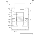
- the accumulator 40 is provided in the piston rod 10.
- the accumulator 240 has a free piston 43 as a partition member that partitions the air chamber 41 and the liquid chamber 42, and the first passage 30, the check valve 50, the free piston 43, and a passage 321 that communicates the anti-rod side chamber 3 and the liquid chamber 42 are provided in the piston rod 310.
- the rod side chamber 2 is filled with gas, and the rod side chamber 2 and the air chamber 41 are in communication with each other.
- the anti-rod side chamber 3 and the liquid chamber 42 are in communication with each other, and hydraulic oil is supplied and discharged to the anti-rod side chamber 3.
- the fluid pressure cylinder unit 101 may be configured such that the anti-rod side chamber 3 is filled with gas, and the anti-rod side chamber 3 and the air chamber 41 are in communication with each other, and the rod side chamber 2 and the liquid chamber 42 are in communication with each other, and hydraulic oil is supplied and discharged to the rod side chamber 2.
- the fluid pressure cylinder unit 101 may be used in a vertically inverted orientation from that shown in FIG. 1.
- the fluid pressure cylinder is the lift cylinder 100 that raises and lowers the forks of a forklift.
- the fluid pressure cylinder is not limited to this, and may be a cylinder other than the cylinder mounted on a forklift, as long as one of the rod side chamber 2 and the anti-rod side chamber 3 is filled with gas and hydraulic fluid is supplied and discharged to the other to cause the piston rod 10 to reciprocate.
- the fluid pressure cylinder may be a double-rod type cylinder.
- the fluid pressure cylinder unit 101, 201, 301, 401 includes a lift cylinder 100, 400 as a fluid pressure cylinder having a cylinder tube 1, a piston rod 10, 310 that is reciprocally disposed within the cylinder tube 1 and divides the cylinder tube 1 into a first chamber and a second chamber, an accumulator 40, 240 having an air chamber 41 that can be filled with gas and a liquid chamber 42 that can be filled with liquid, and a first passage 30 that connects the first chamber to the air chamber 41 of the accumulator 40, 340.
- the first chamber is filled with gas
- the piston rod 10, 310 reciprocates as hydraulic fluid is supplied to and discharged from the second chamber.
- the first passage 30 is provided with a check valve 50 that serves as a valve that can only allow gas to flow from the first chamber to the air chamber 41 of the accumulator 40, 340.
- the gas filled in the first chamber is pressurized and guided through the first passage 30 and the check valve 50 to the air chamber 41 of the accumulator 40, 340, where it is filled.
- This allows the high-pressure gas discharged from the first chamber to be effectively used as the gas filled in the air chamber 41 of the accumulator 40, 340.
- the second chamber is connected to the fluid chamber 42 of the accumulator 40 and 340.
- the second chamber and the liquid chamber 42 of the accumulator 40, 340 are in communication. Therefore, the vibration of the object driven by the lift cylinder 100, 400 can be absorbed by the accumulator 40, 340.
- the fluid pressure cylinder unit 201 further includes a second passage 31 that is connected between the first chamber in the first passage 30 and the check valve 50 and communicates with the atmosphere, and a check valve 51 is provided in the second passage 31 to allow gas to flow only from the atmosphere to the first passage 30.
- This configuration prevents a drop in pressure inside the air chamber 41 of the accumulator 40.
- the fluid pressure cylinder unit 201 further includes a third passage 33 connected between the first chamber in the first passage 30 and the check valve 50, and the third passage 33 is provided with a relief valve 52 that opens when the pressure in the first passage 30 reaches a predetermined pressure.
- This configuration prevents the pressure in the air chamber 41 of the accumulator 40 from exceeding the set pressure.
- the accumulator 340 further has a free piston 43 as a partition member that separates the air chamber 41 and the liquid chamber 42, and the first passage 30, the check valve 50, and the free piston 43 are provided within the piston rod 310.
- This configuration allows the fluid pressure cylinder unit 401 to be made compact.
- the air chamber 41 is not filled with high-pressure gas before the lift cylinders 100, 400 are operated. Therefore, the accumulators 40, 340 can be handled safely and easily.
Landscapes
- Engineering & Computer Science (AREA)
- Physics & Mathematics (AREA)
- Fluid Mechanics (AREA)
- Mechanical Engineering (AREA)
- General Engineering & Computer Science (AREA)
- Supply Devices, Intensifiers, Converters, And Telemotors (AREA)
- Actuator (AREA)
- Forklifts And Lifting Vehicles (AREA)
Priority Applications (1)
| Application Number | Priority Date | Filing Date | Title |
|---|---|---|---|
| CN202380067104.1A CN119948263A (zh) | 2022-11-04 | 2023-10-19 | 流体压力缸单元 |
Applications Claiming Priority (2)
| Application Number | Priority Date | Filing Date | Title |
|---|---|---|---|
| JP2022-177559 | 2022-11-04 | ||
| JP2022177559A JP2024067462A (ja) | 2022-11-04 | 2022-11-04 | 流体圧シリンダユニット |
Publications (1)
| Publication Number | Publication Date |
|---|---|
| WO2024095784A1 true WO2024095784A1 (ja) | 2024-05-10 |
Family
ID=90930492
Family Applications (1)
| Application Number | Title | Priority Date | Filing Date |
|---|---|---|---|
| PCT/JP2023/037834 Ceased WO2024095784A1 (ja) | 2022-11-04 | 2023-10-19 | 流体圧シリンダユニット |
Country Status (3)
| Country | Link |
|---|---|
| JP (1) | JP2024067462A (https=) |
| CN (1) | CN119948263A (https=) |
| WO (1) | WO2024095784A1 (https=) |
Citations (3)
| Publication number | Priority date | Publication date | Assignee | Title |
|---|---|---|---|---|
| JPS50141772A (https=) * | 1974-05-01 | 1975-11-14 | ||
| JPH01126458U (https=) * | 1988-02-23 | 1989-08-29 | ||
| JP2015014328A (ja) * | 2013-07-05 | 2015-01-22 | カヤバ工業株式会社 | 流体圧シリンダ |
-
2022
- 2022-11-04 JP JP2022177559A patent/JP2024067462A/ja active Pending
-
2023
- 2023-10-19 CN CN202380067104.1A patent/CN119948263A/zh active Pending
- 2023-10-19 WO PCT/JP2023/037834 patent/WO2024095784A1/ja not_active Ceased
Patent Citations (3)
| Publication number | Priority date | Publication date | Assignee | Title |
|---|---|---|---|---|
| JPS50141772A (https=) * | 1974-05-01 | 1975-11-14 | ||
| JPH01126458U (https=) * | 1988-02-23 | 1989-08-29 | ||
| JP2015014328A (ja) * | 2013-07-05 | 2015-01-22 | カヤバ工業株式会社 | 流体圧シリンダ |
Also Published As
| Publication number | Publication date |
|---|---|
| JP2024067462A (ja) | 2024-05-17 |
| CN119948263A (zh) | 2025-05-06 |
Similar Documents
| Publication | Publication Date | Title |
|---|---|---|
| US8100236B2 (en) | Shock absorber having self pumping unit | |
| SK148198A3 (en) | Device for saving energy | |
| US20110227301A1 (en) | Vehicle Height Adjusting Apparatus | |
| US10072680B2 (en) | Apparatus for the energy-optimized hydraulic control of at least one double-action working cylinder | |
| CN112243413B (zh) | 用于带水平调节的车辆底盘的减振器单元 | |
| CN110374958A (zh) | 蓄能器与液压缸复合装置 | |
| WO2024095784A1 (ja) | 流体圧シリンダユニット | |
| KR20140094325A (ko) | 압력 부스터의 메인에어 급기용 바이패스 장치 | |
| US7568562B2 (en) | Self-pumping hydropneumatic spring strut | |
| CN202346713U (zh) | 一种缓冲保护活塞缸 | |
| FR2908485B1 (fr) | Amortisseur compact pour atterrisseur d'aeronef, et atterrisseur comportant un tel amortisseur | |
| JP2005248627A (ja) | コンクリートポンプ車両における制振装置 | |
| JP6692686B2 (ja) | フォークリフト | |
| CN105782137B (zh) | 一种超高压蓄能器 | |
| JP6618542B2 (ja) | 圧縮装置 | |
| KR940022987A (ko) | 펌프기계 및 이를 이용하는 발전기시스템 | |
| WO2025100225A1 (ja) | 流体圧シリンダユニット | |
| CN105626606B (zh) | 一种混凝土泵送设备液压系统及混凝土泵送设备 | |
| CN113446273B (zh) | 增压输出稳定化装置 | |
| CN205064674U (zh) | 双活塞杆油气弹簧缸 | |
| CN110273868A (zh) | 一种增压减容液压蓄能器 | |
| FI106399B (fi) | Paineakku | |
| CN118829804A (zh) | 流体压力缓冲器 | |
| JP2024067462A5 (https=) | ||
| JP5725520B2 (ja) | 油圧システム及び該油圧システムを備えるフォークリフト |
Legal Events
| Date | Code | Title | Description |
|---|---|---|---|
| 121 | Ep: the epo has been informed by wipo that ep was designated in this application |
Ref document number: 23885546 Country of ref document: EP Kind code of ref document: A1 |
|
| DPE1 | Request for preliminary examination filed after expiration of 19th month from priority date (pct application filed from 20040101) | ||
| WWE | Wipo information: entry into national phase |
Ref document number: 202380067104.1 Country of ref document: CN |
|
| WWP | Wipo information: published in national office |
Ref document number: 202380067104.1 Country of ref document: CN |
|
| NENP | Non-entry into the national phase |
Ref country code: DE |
|
| 122 | Ep: pct application non-entry in european phase |
Ref document number: 23885546 Country of ref document: EP Kind code of ref document: A1 |