WO2024090144A1 - 部分分割炭素繊維束を製造する方法 - Google Patents
部分分割炭素繊維束を製造する方法 Download PDFInfo
- Publication number
- WO2024090144A1 WO2024090144A1 PCT/JP2023/035865 JP2023035865W WO2024090144A1 WO 2024090144 A1 WO2024090144 A1 WO 2024090144A1 JP 2023035865 W JP2023035865 W JP 2023035865W WO 2024090144 A1 WO2024090144 A1 WO 2024090144A1
- Authority
- WO
- WIPO (PCT)
- Prior art keywords
- carbon fiber
- fiber bundle
- less
- protrusion
- partial
- Prior art date
- Legal status (The legal status is an assumption and is not a legal conclusion. Google has not performed a legal analysis and makes no representation as to the accuracy of the status listed.)
- Ceased
Links
Images


Classifications
-
- D—TEXTILES; PAPER
- D01—NATURAL OR MAN-MADE THREADS OR FIBRES; SPINNING
- D01F—CHEMICAL FEATURES IN THE MANUFACTURE OF ARTIFICIAL FILAMENTS, THREADS, FIBRES, BRISTLES OR RIBBONS; APPARATUS SPECIALLY ADAPTED FOR THE MANUFACTURE OF CARBON FILAMENTS
- D01F9/00—Artificial filaments or the like of other substances; Manufacture thereof; Apparatus specially adapted for the manufacture of carbon filaments
- D01F9/08—Artificial filaments or the like of other substances; Manufacture thereof; Apparatus specially adapted for the manufacture of carbon filaments of inorganic material
- D01F9/12—Carbon filaments; Apparatus specially adapted for the manufacture thereof
- D01F9/14—Carbon filaments; Apparatus specially adapted for the manufacture thereof by decomposition of organic filaments
- D01F9/32—Apparatus therefor
-
- C—CHEMISTRY; METALLURGY
- C08—ORGANIC MACROMOLECULAR COMPOUNDS; THEIR PREPARATION OR CHEMICAL WORKING-UP; COMPOSITIONS BASED THEREON
- C08J—WORKING-UP; GENERAL PROCESSES OF COMPOUNDING; AFTER-TREATMENT NOT COVERED BY SUBCLASSES C08B, C08C, C08F, C08G or C08H
- C08J5/00—Manufacture of articles or shaped materials containing macromolecular substances
- C08J5/24—Impregnating materials with prepolymers which can be polymerised in situ, e.g. manufacture of prepregs
- C08J5/248—Impregnating materials with prepolymers which can be polymerised in situ, e.g. manufacture of prepregs using pre-treated fibres
-
- D—TEXTILES; PAPER
- D01—NATURAL OR MAN-MADE THREADS OR FIBRES; SPINNING
- D01D—MECHANICAL METHODS OR APPARATUS IN THE MANUFACTURE OF ARTIFICIAL FILAMENTS, THREADS, FIBRES, BRISTLES OR RIBBONS
- D01D11/00—Other features of manufacture
- D01D11/02—Opening bundles to space the threads or filaments from one another
-
- D—TEXTILES; PAPER
- D01—NATURAL OR MAN-MADE THREADS OR FIBRES; SPINNING
- D01F—CHEMICAL FEATURES IN THE MANUFACTURE OF ARTIFICIAL FILAMENTS, THREADS, FIBRES, BRISTLES OR RIBBONS; APPARATUS SPECIALLY ADAPTED FOR THE MANUFACTURE OF CARBON FILAMENTS
- D01F11/00—Chemical after-treatment of artificial filaments or the like during manufacture
- D01F11/10—Chemical after-treatment of artificial filaments or the like during manufacture of carbon
- D01F11/14—Chemical after-treatment of artificial filaments or the like during manufacture of carbon with organic compounds, e.g. macromolecular compounds
-
- D—TEXTILES; PAPER
- D02—YARNS; MECHANICAL FINISHING OF YARNS OR ROPES; WARPING OR BEAMING
- D02J—FINISHING OR DRESSING OF FILAMENTS, YARNS, THREADS, CORDS, ROPES OR THE LIKE
- D02J1/00—Modifying the structure or properties resulting from a particular structure; Modifying, retaining, or restoring the physical form or cross-sectional shape, e.g. by use of dies or squeeze rollers
- D02J1/18—Separating or spreading
Definitions
- the present invention relates primarily to a method for producing a partially split carbon fiber bundle.
- This application claims priority based on Japanese Patent Application No. 2022-173173 filed with the Japan Patent Office on October 28, 2022, and Japanese Patent Application No. 2023-120315 filed with the Japan Patent Office on July 24, 2023, the contents of which are incorporated herein by reference.
- CFRP The mechanical properties of CFRP obtained by curing a prepreg in which a random mat type reinforcing material made of chopped carbon fiber bundles, such as SMC (sheet molding compound), is impregnated with resin, are affected by the bundle size of the chopped carbon fiber bundles, i.e., the number of carbon fiber filaments that make up the bundle. SMC using chopped carbon fiber bundles with smaller bundle size as reinforcing material can give CFRP with better mechanical properties (Patent Document 1).
- partial division refers to partially dividing an original continuous fiber bundle into a plurality of sub-bundles.
- the objects of the present invention include the following: - To provide a technique for producing partially split carbon fiber bundles with stable quality. - To provide partially split carbon fiber bundles suitable as raw materials for SMC. - Prevent deterioration in the quality of the partially divided carbon fiber bundles due to problems during the partial division process. Preventing a decrease in the production efficiency of partially divided carbon fiber bundles due to problems during the partial division process.
- a method for producing partially split carbon fiber bundles in which carbon fiber bundles are continuously supplied from a carbon fiber production line to a partial splitting line connected to the carbon fiber production line, and are subjected to a partial splitting process in a partial splitting section provided in the partial splitting line.
- a method for manufacturing partially divided carbon fiber bundles by subjecting a carbon fiber bundle to a partial division process, the partial division process including intermittently piercing the carbon fiber bundle traveling along its own longitudinal direction with a protrusion of a division jig having a protrusion, the protrusion being formed by a needle, and the needle being inclined so as to fall downstream in the traveling direction of the carbon fiber bundle when pierced into the carbon fiber bundle.
- a method for manufacturing partially divided carbon fiber bundles by subjecting a carbon fiber bundle to a partial division process, the partial division process including intermittently piercing the carbon fiber bundle traveling along its own longitudinal direction with a protrusion of a division jig having a protrusion, the protrusion being formed of a plate, and when the plate is pierced into the carbon fiber bundle, the edge of the plate facing the upstream side in the running direction of the carbon fiber bundle is inclined so as to fall toward the downstream side in the running direction of the carbon fiber bundle in the portion where the plate is pierced into the carbon fiber bundle.
- a method for manufacturing partially divided carbon fiber bundles by subjecting a carbon fiber bundle to a partial division process, the partial division process including intermittently piercing the carbon fiber bundle traveling along its longitudinal direction with a protrusion of a division jig having a protrusion, the protrusion being formed of a plate, the plate-shaped protrusion having at least one convex corner with an interior angle of 90° or more but no convex corners with an interior angle of less than 90°, and the number of the convex corners of the protrusion with an interior angle of 90° or more that are pierced into the carbon fiber bundle does not exceed one in the partial division process.
- a method for manufacturing a partially divided carbon fiber bundle by subjecting a carbon fiber bundle to a partial division process, the partial division process including intermittently piercing the carbon fiber bundle running along its longitudinal direction with a protrusion of a division jig having a protrusion, the protrusion being formed of a plate, the plate-shaped protrusion having two right-angled corners, and only one of the two right-angled corners being pierced into the carbon fiber bundle in the partial division process.
- a method for manufacturing a partially divided carbon fiber bundle by subjecting a carbon fiber bundle to a partial division process, the partial division process including intermittently piercing the carbon fiber bundle running along its longitudinal direction with a protrusion of a division jig having a protrusion, the protrusion being formed using a rectangular plate, and in the partial division process, only one of the four right-angled corners of the rectangular plate is pierced into the carbon fiber bundle.
- a method for manufacturing a partially divided carbon fiber bundle by subjecting a carbon fiber bundle to a partial division process, the partial division process including swinging a division jig having a protrusion to intermittently pierce the protrusion into the carbon fiber bundle traveling along its own longitudinal direction.
- a method for manufacturing a partially divided carbon fiber bundle by subjecting a carbon fiber bundle to a partial division process, the partial division process including intermittently piercing the carbon fiber bundle traveling along its own longitudinal direction with a protrusion of a division jig having a protrusion, and blowing compressed air onto the protrusion of the division jig while the partial division process is being performed.
- a method for manufacturing a partially divided carbon fiber bundle by subjecting a carbon fiber bundle to a partial division process, the partial division process including intermittently piercing the carbon fiber bundle running along its longitudinal direction with a protrusion of a division jig having a protrusion, the division jig having (n+1) or more protrusions, and the carbon fiber bundle being partially divided into n or (n+1) sub-bundles in the partial division process.
- n is an integer of 2 or more.
- the present invention provides an improvement in the method for producing partially split carbon fiber bundles.
- FIG. 1 shows an example of a production line for partially split carbon fiber bundles including a partially splitting line.
- FIG. 2 shows an example of a production line for partially split carbon fiber bundles including a partially splitting line.
- FIG. 3 is an explanatory diagram of the x-, y- and z-directions in a partially divided section.
- FIG. 4 is a perspective view showing an example of a dividing jig in which the protrusions are formed by needles.
- FIG. 5 is a view of the dividing jig of FIG. 5 as viewed from the u direction.
- FIG. 6 is a view of the dividing jig of FIG. 5 as viewed from the s direction.
- FIG. 7 shows examples of shapes that the tapered tip of the needle may have.
- FIG. 8 shows an example of a method for manufacturing a dividing jig.
- FIG. 9 shows an example of a method for manufacturing a split jig.
- FIG. 10 is a perspective view showing an example of a dividing jig in which the protruding portion is formed of a plate.
- FIG. 11 is a view of the dividing jig of FIG. 10 as viewed from the u direction.
- FIG. 12 is a view of the dividing jig of FIG. 10 as viewed from the s direction.
- FIG. 13 shows an embodiment of a process for dividing a carbon fiber bundle into portions using a dividing jig having protruding portions formed with needles.
- FIG. 14 shows an embodiment of a process for dividing a carbon fiber bundle into portions using a dividing jig having protruding portions formed with needles.
- FIG. 15 shows an embodiment of a process for partially dividing a carbon fiber bundle using a dividing jig having protruding portions formed with needles.
- FIG. 16 shows an embodiment of a process for partially dividing a carbon fiber bundle using a dividing jig having protruding portions formed of plates.
- FIG. 17 shows an embodiment of a process for partially dividing a carbon fiber bundle using a dividing jig having protruding portions formed of plates.
- FIG. 18 is a plan view showing an example of a partially split carbon fiber bundle.
- FIG. 19 shows a situation that may occur if the position of the carbon fiber bundle in the y direction shifts while the protrusion of the dividing jig is not inserted.
- FIG. 20 shows a situation that may occur if the position of the carbon fiber bundle in the y direction shifts while the protrusion of the dividing jig is not inserted.
- FIG. 21 shows a situation that can occur if the position of the carbon fiber bundle in the y direction shifts while the protrusion of the dividing jig is not inserted.
- FIG. 22 is a perspective view showing an example of a slitter roll having a slit blade with a missing portion.
- FIG. 23 is a photograph showing the dividing jig after it has been used in the partial dividing process.
- FIG. 24 is a photograph showing the dividing jig after it has been used in the partial dividing process.
- FIG. 25 is a photograph showing the dividing jig after it has been used in the partial dividing process.
- FIG. 26 is a photograph showing the dividing jig after it has been used in the partial dividing process.
- Partial Splitting Line One embodiment of the present invention relates to a method for producing a partially split carbon fiber bundle.
- a partial dividing line 2 having a partial dividing section 1 is provided, for example as shown in FIG.
- an undivided carbon fiber bundle 3 as a starting material is unwound from a spool and supplied to a partial division section 1 .
- the bundle size of the carbon fiber bundle 3, i.e., the number of carbon fiber filaments constituting the carbon fiber bundle 3, is usually 12K or more, and may be 15K or more, 24 or more, 36K or more, 48K or more, etc., and is usually 120K or less, and may be 100K or less, 80K or less, 60K or less, etc., but is not limited thereto.
- K is a symbol meaning 1000, and for example, 12K means 12,000 and 120K means 120,000.
- the carbon fiber bundle 3 is subjected to a partial division process to become a partially divided carbon fiber bundle 4.
- the partial division process can be performed, for example, by intermittently piercing the carbon fiber bundle 3 running along the longitudinal direction (fiber direction) with a needle or a plate, but other tools may also be used.
- the partial division process of the carbon fiber bundles 3 in the partial division section can be performed by using a slitter roll having a slit blade provided on the circumferential surface thereof with a cutout portion.
- An example of such a slitter roll is shown in Fig. 22.
- a cutout portion 53 is provided in a slit blade 52 provided on a circumferential surface 51.
- the partially divided carbon fiber bundles 4 coming out of the partially divided section are wound up on another spool.
- the carbon fiber production line 5 includes, in order from the upstream side, a calcination section 7 in which precursor fiber bundles 6 made of polyacrylonitrile are calcined to form carbon fiber bundles, a surface treatment section 8 in which surface treatment is performed to introduce functional groups onto the carbon fiber surfaces, and a sizing section 9 in which the carbon fiber bundles are sized.
- the calcination section 7 usually includes a flameproofing section and a carbonization section as subsections, and may further include a graphitization section.
- the precursor fiber bundle 6 may be twisted, for example, at 5 to 20 turns/m.
- the unsplit carbon fiber bundle 3 is untwisted downstream of the baking section 7, preferably to an untwisted state. This untwisting is preferably performed before the completion of sizing, and in one example, may be performed upstream of the surface treatment section 8.
- the unsplit carbon fiber bundle 3 is produced in the carbon fiber production line 5, and then supplied to the partial division line 2 without being wound around a spool, and is partially divided in the partial division section 1 of the partial division line 2 to become a partially divided carbon fiber bundle 4.
- the partially divided carbon fiber bundle 4 is wound around a spool. Not winding the carbon fiber bundle produced in the carbon fiber production line onto a spool before dividing it into portions is advantageous in stabilizing the quality of the partially divided carbon fiber bundles, because the carbon fiber bundle does not develop a curl before being supplied to the partially dividing line, and therefore the posture of the carbon fiber bundle when it travels through the partially dividing section is stable.
- Carbon fiber bundles are prone to curling because they have plasticity, and more specifically, because a resin containing a low molecular weight compound called a sizing agent is used to bond the carbon fibers together. Therefore, even if the carbon fiber bundle is poured into a packaging container using the method disclosed in JP 2012-188773 A, for example, instead of being wound onto a spool, the shape of the carbon fiber bundle will become curled. In general, carbon fiber bundles that have been packaged even once before being supplied to the partial division line will become curled, making their posture unstable when they run through the partial division section.
- the posture of the carbon fiber bundle when it runs through the partial division section becomes particularly unstable when the carbon fiber bundle that is traverse wound around the spool is unwound and used, because in the traverse winding, the carbon fiber bundle is easily twisted locally when the moving direction of the traverse guide is reversed, and the twisted carbon fiber bundle does not completely return to its original state even after being unwound from the spool.
- the partial division process if the twisted portion of the carbon fiber bundle is processed with a tool such as a needle or plate, many carbon fibers will be cut, resulting in a problem that the carbon fiber bundle after partial division will be severely frayed.
- a carbon fiber bundle containing almost no twisted portions can be supplied to the partial division line, so that fluffing of the carbon fiber bundle in the partial division process is also suppressed.
- the carbon fiber bundles are sized before being fed to the partial division line. If the carbon fiber bundles are subjected to partial division processing without sizing, a large amount of fiber breakage will occur and the carbon fiber bundles will become significantly frayed. This is because the introduction of functional groups to the carbon fiber surface by surface treatment significantly increases the following two frictional forces.
- One of the two frictional forces is the frictional force acting between adjacent carbon fibers in the bundle, and the other is the frictional force acting between the carbon fibers and tools such as needles and plates used in the partial division processing.
- the reason why fraying associated with partial division processing is suppressed in sized carbon fiber bundles is that the sizing agent introduced into the carbon fiber bundle by sizing acts as a lubricant that reduces these frictional forces.
- the carbon fiber bundle is passed through a sizing bath and then dried. Since the carbon fibers are fixed to each other by sizing, it is desirable to apply high tension to the carbon fiber bundle in the sizing section 9 using a tensioning mechanism such as a dancer roll to sufficiently align the carbon fibers. On the other hand, it is desirable to apply high tension to the carbon fiber bundles 3 at the partial division line 2 as well so that a tool such as a needle or plate can reliably pierce the carbon fiber bundles 3 at the partial division section 1 .
- a single tensioning mechanism may be used as both the tensioning mechanism for the sizing section 9 and the tensioning mechanism for the partial division line 2.
- the force generated by the contraction of the precursor fiber bundle 6 due to the firing in the firing section 7 can also be used to apply tension to the carbon fiber bundles in the sizing section 9 and the partial division line 2.
- the carbon fiber bundle is divided into parts in the partial division section provided on the partial division line.
- the subdivision process is carried out by piercing a needle or plate into the carbon fiber bundle passing through the subdivision section.
- the carbon fiber bundles fed to the partial division section have a flat shape, and therefore have a width direction and a thickness direction in addition to a longitudinal direction (fiber direction).
- the width direction and the thickness direction are each perpendicular to the longitudinal direction and perpendicular to each other.
- a tension is applied to the carbon fiber bundle traveling through the partial division section so that the longitudinal direction is parallel to a first direction and the width direction is parallel to a second direction perpendicular to the first direction.
- the carbon fiber bundle passes through the partial division section in a state where it is stretched substantially straight along the first direction without being twisted and suspended in the air.
- the first direction is referred to as the x-direction in the sub-divided section
- the second direction is referred to as the y-direction in the sub-divided section, as shown in Figure 3.
- the direction perpendicular to both the x-direction and the y-direction is referred to as the z-direction.
- the x-direction may be perpendicular, inclined, or parallel to the direction of gravity.
- the y direction may also be perpendicular, inclined, or parallel to the direction of gravity.
- a splitting jig having a protrusion formed by a needle or a plate is installed in the partial splitting section.
- the carbon fiber bundles fed to the partial splitting line are intermittently pierced by the protrusion of the splitting jig when passing through the partial splitting section, thereby being split into portions.
- the number of protrusions that one splitting jig has is typically two or more, but may be one.
- the minimum number of protrusions that a splitting jig should have depends on how many sub-bundles the carbon fiber bundle should be partially divided into. How many sub-bundles the carbon fiber bundle should be partially divided into is naturally determined by the bundle size of the carbon fiber bundle that is the starting material, and the bundle size of the sub-bundles to be formed by partial division.
- FIGS. 4, 5 and 6 show an example of a dividing jig in which the protrusions are formed by needles.
- the dividing jig 20A shown in FIGS. 4, 5 and 6 has a base 21 and eight needles 22 fixed to the base 21.
- the eight needles are parallel to each other and extend along the u direction shown in the figure.
- the eight needles are also arranged at equal intervals along the t direction perpendicular to the u direction. All eight needles have the same length, and the straight lines connecting their tips are parallel to the t direction.
- a needle has at least a body, which is a part having a constant cross-sectional shape and area.
- the shape of the body is preferably a cylinder, but may be an elliptical cylinder, or may be a triangular prism, a square prism, a hexagonal prism, or any other prismatic prism.
- the cross-sectional shape of the elliptical cylinder may be an ellipse or an oval.
- the tip of the needle is preferably tapered so as to facilitate piercing the carbon fiber bundle.
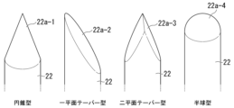
- Examples of shapes that the tapered tip of a needle may have are shown in Figure 7. From the left, Figure 7 illustrates needles having a conical tip 22a-1, a uniplanar tapered tip 22a-2, a biplanar tapered tip 22a-3, and a hemispherical tip 22a-4.
- the diameter of the needle body is preferably 1 mm or less, more preferably 0.9 mm or less, and even more preferably 0.8 mm or less.
- the smaller the diameter of the body the easier it is to divide the carbon fiber bundle into sub-bundles of smaller bundle size. Therefore, it is preferable that the diameter of the body is smaller, but if it is too small, the rigidity decreases and the needle is likely to not penetrate the carbon fiber or to bend. Therefore, the diameter of the body is preferably 0.3 mm or more, more preferably 0.4 mm or more, and may be 0.5 mm or more. When the body is not cylindrical, the smallest width of the body is regarded as the diameter.
- the needle tip is hemispherical.
- the tip may be tapered other than hemispherical, with a rounded end or a terminal surface perpendicular to the axial direction.
- the dividing jig 20A shown in Figures 4, 5 and 6 can be manufactured by preparing a base 21 having a plurality of holes 21a formed therein, as shown in Figure 8, inserting the base of each needle 22 into each hole 21a, and then gluing and fixing the base 21 and the needles 22 together.
- the dividing jig 20A shown in Figures 4, 5 and 6 is merely one example of a dividing jig having multiple needles arranged in parallel to each other and fixed to each other. There is no limitation on the method for arranging multiple needles in parallel to each other and fixing them to each other to create a dividing jig.
- a needle 22 may be sandwiched between two plates 24 and fixed with a screw 25.
- the dividing jig 20B shown in FIGS. 10, 11 and 12 has seven spacers 31 and eight plates 32 arranged alternately and fixed to each other.
- the eight plates 32 have the same length, width, and thickness, and the shape of their main surfaces (surfaces perpendicular to the thickness direction) is rectangular.
- the eight plates 32 are parallel to each other, and the long sides of each main surface are parallel to the u direction shown in the figure.
- the eight plates are arranged at equal intervals along the t direction perpendicular to the u direction.
- the seven spacers 31 are stacked alternately with the eight plates 32 on the -u side of the dividing jig 20B.
- the +u side of each plate 32 protrudes relative to the spacers 31.
- the material of the plate 32 is typically a metal, preferably steel such as stainless steel, but is not limited thereto. There is no limitation on the method for fixing the spacer 31 and the plate 32 to each other, and for example, adhesive, clamping, screw fastening, or various other methods can be appropriately applied.
- the thickness of the plate is preferably 1 mm or less, and may be 0.9 mm or less, 0.8 mm or less, 0.7 mm or less, 0.6 mm or less, 0.5 mm or less, 0.4 mm or less, 0.3 mm or less, etc.
- the thinner the plate the easier it is to pierce the carbon fiber bundle and to divide the carbon fiber bundle into sub-bundles with smaller bundle sizes. From this viewpoint, it is preferable that the plate is thinner, but if it is too thin, the rigidity decreases and the plate is likely to not pierce the carbon fiber bundle or to bend. Therefore, the thickness of the plate is preferably 0.1 mm or more, more preferably 0.2 mm or more. When the plate is too thick to easily penetrate the carbon fiber bundles, the edge of the plate may be tapered.
- the dividing jig 20B shown in Figures 10, 11 and 12 shows one preferred embodiment, in which the plate 32 is rectangular, i.e., a square having four right-angled corners (90° interior corners), two of which are included in the protrusions.
- the plate 32 may be a polygon other than a square, such as a triangle, pentagon or hexagon, or may be a concave polygon, or may have no corners, such as an ellipse.
- the plate 32 is preferably polygonal, more preferably quadrangular, and particularly preferably rectangular.
- the partial dividing process of the carbon fiber bundle using the dividing jig is carried out as follows.
- the running direction of the carbon fiber bundle 11 is from left to right in the figures, and the same applies to Figures 16, 17, 19, 20, and 21 described below.
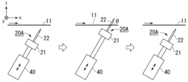
- the dividing jig 20A is linearly reciprocated by the actuator 40, so that the needles 22 intermittently pierce the traveling carbon fiber bundle 11.
- the dividing jig 20A is disposed so that its t direction is parallel to the y direction.
- the dividing jig 20A is swung about an axis 45 by an actuator (not shown), so that the needles 22 intermittently pierce the traveling carbon fiber bundle 11.
- the axis 45 is parallel to the y direction.
- the dividing jig 20A is positioned so that its t direction is parallel to the y direction, and when a cylinder is imagined centered on the axis 45, the longitudinal direction of the needle 22 is parallel to the radial direction of the cylinder.
- This example may be modified so that the splitting jig 20 rotates instead of swinging.
- the dividing jig 20 is swung about an axis 45 by an actuator (not shown), so that the needles 22 intermittently pierce the traveling carbon fiber bundle 11.
- the axis 45 is parallel to the y direction.
- the dividing jig 20A is positioned so that its t direction is parallel to the y direction, and when a cylinder is imagined centered on the axis 45, the longitudinal direction of the needle 22 is inclined relative to the radial direction of the cylinder.
- both the x direction and the y direction may be horizontal, in which case the carbon fiber bundle 11 may be pierced with the needle 22 from below or from above.
- the carbon fiber bundle 11 is divided by keeping the splitting jig 20A stationary for a certain period of time with the needles 22 piercing the traveling carbon fiber bundle 11.
- the needles 22 piercing the carbon fiber bundle 11 are not perpendicular to the traveling direction of the carbon fiber bundle 11, but are inclined so as to fall toward the downstream side (+x direction) of the traveling direction of the carbon fiber bundle 11 (angle ⁇ is smaller than 90°). This advantageously makes it difficult for carbon fiber waste to accumulate in the splitting jig 20.
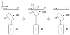
- Figs. 16 and 17 show examples in which a split jig having protruding portions formed of plates is used.
- the dividing jig 20B is linearly reciprocated by the actuator 40, so that the plate 32 intermittently pierces the traveling carbon fiber bundle 11.
- the dividing jig 20B is disposed so that its t direction is parallel to the y direction.
- the carbon fiber bundle 11 is divided by keeping the dividing jig 20B stationary for a certain period of time with the plate 32 piercing the traveling carbon fiber bundle 11.
- the dividing jig 20B is swung about an axis 45 by an actuator (not shown), so that the plate 32 intermittently pierces the traveling carbon fiber bundle 11.
- the axis 45 is parallel to the y direction.
- the splitting jig 20B is positioned so that its t direction is parallel to the y direction, and the carbon fiber bundle 11 is split by keeping the splitting jig 20B stationary for a certain period of time with the plate 32 piercing the running carbon fiber bundle 11.
- the same effect can be obtained by making the number of the multiple convex corners that are stuck into the carbon fiber bundle during the partial dividing process not exceed 1.
- the number of convex corners of the plate-shaped protruding portion may be only one.
- the inner angle of the convex corner that pierces the carbon fiber bundle is set to 90° or more, so that the above effect becomes more remarkable. From the viewpoint of making it easier for the protrusion to pierce the carbon fiber bundle, the inner angle is preferably 120° or less.
- the motion of the dividing jig is preferably a reciprocating motion rather than a rotational motion.
- reciprocating motion include linear reciprocating motion and swinging motion.
- Reciprocating motion is preferred because it prevents winding when a problem occurs in which the carbon fiber bundle (all or some of the sub-bundles) breaks. If winding occurs, the production line must be stopped and recovery will take a long time.
- a suitable example of an actuator for reciprocating the dividing jig is an air cylinder, but is not limited thereto, and may be an electric motor.
- the dividing jig is swung so that when the protrusion is inserted into the carbon fiber bundle, it moves in the opposite direction to the running direction of the carbon fiber bundle, and when the protrusion is removed from the carbon fiber bundle, it moves in the same direction as the running direction of the carbon fiber bundle. This makes it less likely that a protrusion that has been inserted into the carbon fiber bundle will not come out, or that when the protrusion is removed from the carbon fiber bundle, the carbon fiber bundle will be pulled by the protrusion and vibrate significantly, resulting in poor insertion of the protrusion.
- the carbon fiber bundle travels with the protruding portion of the dividing jig stuck therein, so that slits are formed in the carbon fiber bundle.
- the formation of the slits is interrupted.
- a partially divided carbon fiber bundle in which the carbon fiber bundle is partially divided into a plurality of sub-bundles is obtained.
- a partially divided carbon fiber bundle in which the divided portions into five sub-bundles are intermittently formed along the longitudinal direction is shown in Fig. 18.
- Fig. 18 is a plan view of the partially divided carbon fiber bundle 4 as viewed from the thickness direction.
- the partially divided carbon fiber bundle 4 has four slit rows formed therein, namely, a first slit row R S1 , a second slit row R S2 , a third slit row R S3 and a fourth slit row R S4 .
- the first slit row R S1 is composed of a plurality of first slits S1 arranged along the longitudinal direction of the partially split carbon fiber bundle 4.
- the second slit row R S2 is composed of a plurality of second slits S2 arranged along the longitudinal direction of the partially split carbon fiber bundle 4.
- the third slit row R S3 is composed of a plurality of third slits S3 arranged along the longitudinal direction of the partially split carbon fiber bundle 4.
- the fourth slit row R S4 is composed of a plurality of fourth slits S4 arranged along the longitudinal direction of the partially split carbon fiber bundle 4.
- the slit length Ls which is the length of the first to fourth slits S1, S2, S3, S4, is approximately the product of the time from when the protruding portion is pierced into the carbon fiber bundle until it is pulled out and the running speed of the carbon fiber bundle.
- the slit gap length L G which is the length of the slit gap G S in each of the first to fourth slit rows R S1 , R S2 , R S3 , R S3 , is approximately the product of the time from when the protruding portion is pulled out of the carbon fiber bundle until it next pierces the carbon fiber bundle and the running speed of the carbon fiber bundle. Since the motion period of the dividing jig is constant, the slit length L S and the inter-slit gap length L G are constant within any slit row and are common to all slit rows.
- the slit length Ls is preferably 20 cm or more, more preferably 40 cm or more, and even more preferably 60 cm or more.
- the longer the slit length Ls the more advantageous it is because the chopped carbon fiber bundle obtained when cutting the split carbon fiber bundle 4 to produce the SMC contains more bundles of the same size as the sub-bundles.
- the fiber length of the chopped carbon fiber bundle is preferably 5 to 60 mm, more preferably 10 to 30 mm, and can even be 20 mm or less. From this perspective, there is no particular upper limit to the slit length Ls.
- the slit length Ls is preferably 300 cm or less, more preferably 200 cm or less, and even more preferably 150 cm or less.
- the slit length Ls can be set, for example, to 60 cm or more and less than 100 cm, 100 cm or more and less than 150 cm, 150 cm or more and less than 200 cm, 200 cm or more and less than 250 cm, or 250 cm or more and less than 300 cm.
- the inter-slit gap length L G is preferably 1 cm or less, more preferably 5 mm or less, further preferably 2 mm or less, and may be 1 mm or less.
- the above description of the slit length L.sub.2 and the slit gap length L.sub.2 is not limited to the partially divided carbon fiber bundle partially divided into five sub-bundles, but also applies to the partially divided carbon fiber bundle partially divided into four or less or six or more sub-bundles.
- the bundle size of the sub-bundles formed by the partial division process is not particularly limited.
- the bundle size of the sub-bundles is preferably set to 6K or less, more preferably 4K or less, even more preferably 3K or less, and even more preferably 2K or less.
- the size of the sub-bundles when partially dividing a carbon fiber bundle having a bundle size of 36K to 120K is preferably set to 18K or less, and may be, for example, 15K or less, 12K or less, 9K or less, 6K or less, 4K or less, 3K or less, 2K or less, etc.
- the bundle size of the sub-bundle is preferably 0.5K or more, and more preferably 1K or more.
- n is an integer of 2 or more
- the dividing jig must have at least (n-1) protrusions.
- the dividing jig must be arranged in the partial division section so that the (n-1) protrusions can be inserted into the carbon fiber bundle simultaneously.
- a grooved guide roller with a groove width that matches the width of the carbon fiber bundle can be used.
- the idea can be changed so that, instead of dividing the carbon fiber bundle into n sub-bundles using a dividing jig with exactly (n-1) protrusions, the number of protrusions on the dividing jig can be (n+1) or more, so that the carbon fiber bundle is divided into at least n sub-bundles.
- a certain degree of variation in the y-direction position of the carbon fiber bundle within the partial division section is tolerated so that the running speed of the carbon fiber bundle does not need to be reduced, and even if there is a variation in the y-direction position, the number of protrusions that simultaneously pierce the carbon fiber bundle does not fall below (n-1).
- n 9 and the dividing jig has (n+1) or 10 needles as protrusions.
- the y-direction position of the carbon fiber bundle 11 shifts slightly, so that the number of protrusions that will next be stuck into the carbon fiber bundle 11 is nine.
- the number of sub-bundles increases from nine to ten, but no sub-bundles with abnormally large bundle sizes are formed.
- the position of the carbon fiber bundle 11 in the y direction is significantly shifted after the eight protrusions (needles 22) of the dividing jig 20A that have been stuck into the carbon fiber bundle 11 are pulled out, and therefore the number of protrusions that will next be stuck into the carbon fiber bundle 11 remains at 8. In this case as well, no sub-bundles with abnormally large bundle sizes are formed.
- the longitudinal direction of the needle 22 is parallel to the z direction when the needle 22 is inserted into the carbon fiber bundle 11, but this is not limited to this.
- the needle 22 may be inclined so as to fall toward the downstream side in the running direction of the carbon fiber bundle 11 when the needle 22 is inserted into the carbon fiber bundle 11.
- the number of protrusions of the splitting jig that simultaneously penetrate the carbon fiber bundle is set so that the bundle size of the sub-bundles formed is equal to or less than a predetermined upper limit. Therefore, if the bundle size of the carbon fiber bundle before splitting is 15K and the upper limit of the bundle size of the sub-bundles is approximately 5K, the number of protrusions of the splitting jig that simultaneously penetrate can be set to 2 or 3. If the bundle size of the carbon fiber bundle before splitting is 50K and the upper limit of the bundle size of the sub-bundles is approximately 10K, the number of protrusions of the splitting jig that simultaneously penetrate can be set to 4 or 5.
- the carbon fiber bundles supplied to the partial division section may have fiber waste attached thereto, which is generated when a small portion of the carbon fibers is cut in an upstream process.
- the partial division process in the partial division section may also cut the carbon fibers, generating fiber waste.
- Such fiber waste is likely to get caught on the protruding portion of the division jig. If this fiber waste accumulates and becomes large cotton waste and adheres to the partial carbon fiber bundles, it may deteriorate the quality of the SMC manufactured using the partial carbon fiber bundles. Therefore, in a preferred embodiment, compressed air may be blown onto the protruding portion of the dividing jig during the partial dividing process to blow off the caught fiber waste and/or cotton dust. The compressed air may be blown continuously or intermittently. More preferably, a suction nozzle is provided near the dividing jig to remove the fiber waste and/or cotton dust blown off by the compressed air, thereby preventing them from adhering to the partially divided carbon fiber bundles.
- Embodiment A1 A method for producing a partially split carbon fiber bundle, in which carbon fiber bundles are continuously supplied from a carbon fiber production line to a partial splitting line connected to the carbon fiber production line, and are subjected to a partial splitting process in a partial splitting section provided in the partial splitting line.
- Emodiment A2 The method according to embodiment A1, wherein the carbon fiber production line includes a sizing section, and the carbon fiber bundle is sized in the sizing section before being supplied to the portion division line.
- Emodiment A3 A method according to embodiment A2, in which a single tensioning mechanism serves as both the tensioning mechanism for the sizing section and the tensioning mechanism for the partial dividing line.
- Emodiment A4 A method according to any one of embodiments A1 to A3, in which a force generated due to the contraction of a precursor fiber bundle in the carbon fiber production line is utilized to apply tension to the carbon fiber bundle in the partial division line.
- the partial splitting process includes intermittently piercing the carbon fiber bundle running along its longitudinal direction with a protrusion of a splitting jig having a protrusion.
- Embodiment A17 A method according to embodiment A15 or A16, in which the partial division section has an x direction, a y direction, and a z direction that are perpendicular to each other, and when the longitudinal direction and width direction of the carbon fiber bundle as it passes through the partial division section are parallel to the x direction and the y direction, respectively, the division jig oscillates around an axis parallel to the y direction.
- a slit row consisting of a plurality of slits lined up along the longitudinal direction of the carbon fiber bundle is formed in the carbon fiber bundle, and the length of the plurality of slits is 20 cm or more, preferably 40 cm or more, and more preferably 60 cm or more.
- the length may be 60 cm or more and less than 100 cm, 100 cm or more and less than 150 cm, 150 cm or more and less than 200 cm, 200 cm or more and less than 250 cm, or 250 cm or more and less than 300 cm.
- Embodiment B1 A method for producing partially divided carbon fiber bundles by subjecting a carbon fiber bundle to a partial dividing process, the partial dividing process including intermittently piercing the carbon fiber bundle traveling along its own longitudinal direction with a protrusion of a dividing jig having a protrusion, the protrusion being formed by a needle, and the needle being inclined so as to fall downstream in the traveling direction of the carbon fiber bundle when pierced into the carbon fiber bundle.
- Embodiment B2 A method for producing partially divided carbon fiber bundles by subjecting a carbon fiber bundle to a partial dividing process, the partial dividing process including intermittently piercing a protrusion of a dividing jig having a protrusion into the carbon fiber bundle running along its longitudinal direction, the protrusion being formed of a plate, and when the plate-shaped protrusion is inserted into the carbon fiber bundle, in the portion of the protrusion inserted into the carbon fiber bundle, an edge of the protrusion facing the upstream side in the running direction of the carbon fiber bundle is inclined so as to fall toward the downstream side in the running direction of the carbon fiber bundle.
- Emodiment B3 A method according to embodiment B2, in which the plate-shaped protrusion has at least one convex corner, and in the partial division process, the number of the convex corners of the protrusion that are stuck into the carbon fiber bundle does not exceed one.
- Emodiment B4 A method according to embodiment B2 or B3, in which the plate-shaped protrusion has at least one convex corner with an interior angle of 90° or more but does not have any convex corners with an interior angle of less than 90°, and in which, in the partial division process, the number of the convex corners with an interior angle of 90° or more that are in a state of being stuck into the carbon fiber bundle does not exceed one.
- Emodiment B5 A method according to any one of embodiments B2 to B4, in which the plate-shaped protrusion has two right-angled corners at the protruding end, and in the partial division process, only one of the two right-angled corners of the protrusion is pierced into the carbon fiber bundle.
- Emodiment B6 A method according to any one of embodiments B2 to B5, in which the protrusion is formed using a rectangular plate, and in the partial division process, only one of the four right-angled corners of the rectangular plate penetrates the carbon fiber bundle.
- Embodiment B7 A method for producing partially divided carbon fiber bundles by subjecting a carbon fiber bundle to a partial division process, the partial division process comprising intermittently piercing the carbon fiber bundle running along its longitudinal direction with a protrusion of a division jig having a protrusion, the protrusion being formed of a plate, the plate-shaped protrusion having at least one convex corner with an interior angle of 90° or more but no convex corner with an interior angle of less than 90°, and in the partial division process, the number of the convex corners with an interior angle of 90° or more that are in a state of being pierced into the carbon fiber bundle does not exceed 1.
- Emodiment B8 A method for producing partially divided carbon fiber bundles by subjecting a carbon fiber bundle to a partial division process, the partial division process including intermittently piercing the carbon fiber bundle running along its longitudinal direction with a protrusion of a division jig having a protrusion, the protrusion being formed of a plate, the plate-shaped protrusion having two right-angled corners, and in the partial division process, only one of the two right-angled corners is pierced into the carbon fiber bundle.
- Emodiment B9 A method for producing partially divided carbon fiber bundles by subjecting a carbon fiber bundle to a partial division process, the partial division process including intermittently piercing the carbon fiber bundle running along its longitudinal direction with a protrusion of a division jig having a protrusion, the protrusion being formed using a rectangular plate, and in the partial division process, only one of four right-angled corners of the rectangular plate is pierced into the carbon fiber bundle.
- the dividing jig is reciprocated to intermittently pierce the carbon fiber bundle with the protrusions in the partial dividing process.
- the reciprocating motion may be a linear reciprocating motion or a swinging motion.
- the protrusion moves in the opposite direction to the running direction of the carbon fiber bundle, and when the protrusion comes out of the carbon fiber bundle, the protrusion moves in the same direction as the running direction of the carbon fiber bundle.
- Embodiment B13 A method according to embodiment B11 or B12, in which the space in which the partial division process is performed has an x-direction, a y-direction, and a z-direction which are perpendicular to each other, and the longitudinal direction and width direction of the carbon fiber bundle when passing through the space are parallel to the x-direction and the y-direction, respectively, and the division jig oscillates around an axis parallel to the y-direction.
- Emodiment B17 A method according to embodiment B15 or B16, wherein the bundle size of each of the sub-bundles is 18K or less, preferably 15K or less, more preferably 12K or less, even more preferably 9K or less, and may be 6K or less, 4K or less, 3K or less or 2K or less.
- a slit row consisting of a plurality of slits lined up along the longitudinal direction of the carbon fiber bundle is formed in the carbon fiber bundle, and the length of the plurality of slits is 20 cm or more, preferably 40 cm or more, and more preferably 60 cm or more.
- the length may be 60 cm or more and less than 100 cm, 100 cm or more and less than 150 cm, 150 cm or more and less than 200 cm, 200 cm or more and less than 250 cm, or 250 cm or more and less than 300 cm.
- Emodiment C1 A method for producing partially divided carbon fiber bundles by subjecting a carbon fiber bundle to a partial division process, the partial division process including swinging a division jig having a protrusion to intermittently pierce the protrusion into the carbon fiber bundle traveling along its own longitudinal direction.
- Emodiment C2 A method according to embodiment C1, wherein when the protrusion penetrates the carbon fiber bundle, the protrusion moves in the opposite direction to the running direction of the carbon fiber bundle, and when the protrusion comes out of the carbon fiber bundle, the protrusion moves in the same direction as the running direction of the carbon fiber bundle.
- Emodiment C3 A method according to embodiment C1 or C2, in which the space in which the partial division process is performed has an x-direction, a y-direction, and a z-direction which are perpendicular to each other, and the longitudinal direction and width direction of the carbon fiber bundle when passing through the space are parallel to the x-direction and the y-direction, respectively, and the division jig oscillates around an axis parallel to the y-direction.
- the protrusions are formed with needles.
- Emodiment D1 A method for producing partially divided carbon fiber bundles by subjecting a carbon fiber bundle to a partial division process, the partial division process including intermittently piercing the carbon fiber bundle running along its own longitudinal direction with a protrusion of a dividing jig having a protrusion, and blowing compressed air onto the protrusion of the dividing jig while the partial division process is being performed.
- the protrusion is formed by a needle.
- Emodiment D3 The method according to embodiment D1, wherein the protrusion is formed of a plate.
- Emodiment D6 A method according to embodiment D4 or D5, wherein the bundle size of each of the sub-bundles is 18K or less, preferably 15K or less, more preferably 12K or less, even more preferably 9K or less, and may be 6K or less, 4K or less, 3K or less or 2K or less.
- Emodiment D7 The method according to any of embodiments D1 to D3, wherein the partial splitting process splits the carbon fiber bundle partially into a plurality of sub-bundles, and the bundle size of each of the plurality of sub-bundles is 18K or less, preferably 15K or less, more preferably 12K or less, even more preferably 9K or less, and may be 6K or less, 4K or less, 3K or less, or 2K or less.
- Emodiment D8 The method according to any one of embodiments D1 to D7, in which, in the partial division treatment, a slit row consisting of a plurality of slits lined up along the longitudinal direction of the carbon fiber bundle is formed in the carbon fiber bundle, and the length of the plurality of slits is 20 cm or more, preferably 40 cm or more, and more preferably 60 cm or more, and may be, for example, 60 cm or more and less than 100 cm, 100 cm or more and less than 150 cm, 150 cm or more and less than 200 cm, 200 cm or more and less than 250 cm, or 250 cm or more and less than 300 cm.
- Emodiment E1 A method for producing a partially divided carbon fiber bundle by subjecting a carbon fiber bundle to a partial division process, the partial division process comprising intermittently piercing the carbon fiber bundle running along its own longitudinal direction with a protruding portion of a division jig having a protruding portion, the division jig having (n+1) or more protruding portions, and the carbon fiber bundle is partially divided into n or (n+1) sub-bundles in the partial division process, where n is an integer of 2 or more.
- Emodiment E2 A method according to embodiment E1, wherein the bundle size of each of the sub-bundles is 18K or less, preferably 15K or less, more preferably 12K or less, even more preferably 9K or less, and may be 6K or less, 4K or less, 3K or less or 2K or less.
- the protrusion is formed by a needle.
- the protrusion is formed of a plate.
- a slit row consisting of a plurality of slits lined up along the longitudinal direction of the carbon fiber bundle is formed in the carbon fiber bundle, and the length of the plurality of slits is 20 cm or more, preferably 40 cm or more, and more preferably 60 cm or more.
- the length may be 60 cm or more and less than 100 cm, 100 cm or more and less than 150 cm, 150 cm or more and less than 200 cm, 200 cm or more and less than 250 cm, or 250 cm or more and less than 300 cm.
- a dividing jig having a plurality of needles arranged parallel to each other and fixed to each other as exemplified in Figures 4 to 6 (the same as the dividing jig used in Experiment 3 described later) was installed in the partial division section as a means for partial division treatment.
- the needles were intermittently pierced into the carbon fiber bundle by swinging the dividing jig around a swing axis provided parallel to the width direction of the carbon fiber bundle traveling in the partial division section.
- Experiment 3 A partial division line as shown in FIG. 1 was prepared, and a carbon fiber bundle (TR50S15L, manufactured by Mitsubishi Chemical Co., Ltd.) having 15K filaments, which was produced in a carbon fiber production line (including a sizing section) separate from the partial division line and wound around a bobbin, was pulled out from the bobbin and an attempt was made to perform partial division processing.
- a dividing jig having multiple protrusions each formed by a needle was installed as a means for dividing the specimen into portions.
- the needle was made of stainless steel (SUS304), had a hemispherical tip, and had a cylindrical body with a diameter of 0.8 mm.
- the dividing jig In the dividing jig, more than 15 needles were arranged in parallel at a constant pitch of 1 mm, as in the examples shown in Figures 4 to 6. In the partially divided section, the orientation of the dividing jig was adjusted so that the straight line connecting the tips of the needles was parallel to the width direction of the traveling carbon fiber bundle. Since the width of the undivided carbon fiber bundle was approximately 7 mm, the number of needles that could be inserted into the carbon fiber bundle at the same time was approximately six.
- the splitting jig was held still for 4.2 seconds with the needle piercing the carbon fiber bundle, and within the next 0.2 seconds, the needle was removed from the carbon fiber bundle, and the splitting jig was moved back and forth linearly so as to pierce the carbon fiber bundle again. This operation was repeated.
- the direction of the reciprocating movement of the dividing jig was perpendicular to both the running direction and the width direction of the carbon fiber bundle, i.e., the dividing jig was moved parallel to the z direction in FIG.
- the angle ( ⁇ in the example of FIG. 14 ) between the longitudinal direction of the needle and the running direction of the carbon fiber bundle was set to 45°. That is, during the rest period, the needle was inclined so as to fall at an angle of 45° downstream in the running direction of the carbon fiber bundle.
- partial division of the carbon fiber bundle was attempted in the same manner as in Experiment 3, and there was no problem with the stability of the partial division process.
- the amount of carbon fiber scraps accumulated in the dividing jig by the partial division process for the same period of time was less than that in Experiment 3, as shown in FIG.
- Experiment 5 A fiber-splitting jig was set up in the same manner as in Experiment 4, and while the carbon fiber bundle was being run, the fiber-splitting jig was stationary with a needle pierced into the carbon fiber bundle. When the jig was rotated so that the needle moved in the opposite direction to the running direction of the carbon fiber bundle, it was investigated whether the needle would come out of the carbon fiber bundle. As a result, when the dividing jig was rotated, the carbon fiber bundle was bitten into the dividing jig, and the needle could not be removed from the carbon fiber bundle. This is thought to be because the rotation of the dividing jig caused the needle that had pierced the carbon fiber bundle to tilt toward the upstream side in the running direction of the carbon fiber bundle.
- the orientation of the splitting jig was adjusted so that the straight lines connecting the corners of different rectangular plates were parallel to the width direction of the traveling carbon fiber bundle, and the position of the splitting jig during the stationary period of 4.2 seconds was adjusted so that only one corner of each rectangular plate was pierced into the carbon fiber bundle. Since the width of the unsplit carbon fiber bundle was about 7 mm, the number of rectangular plates that could be pierced into the carbon fiber bundle at the same time was approximately eight.
- the angle ( ⁇ in the example of FIG. 16 ) made by the edge of the rectangular plate facing the upstream side of the running direction of the carbon fiber bundle at the part where the rectangular plate pierced the carbon fiber bundle and the running direction was set to three different angles of 30°, 45°, and 60°.
- the results showed that there was no problem with the stability of the partial division process.
- the larger the angle the larger the amount of carbon fiber scraps accumulated in the division jig by the partial division process for the same time.
- Figure 25 is a photograph of the division jig after the partial division process was performed with the angle set to 60°
- Figure 26 is a photograph of the division jig after the partial division process was performed for the same period of time with the angle set to 30°.
- the present invention provides an improved method for producing partially split carbon fiber bundles.
Landscapes
- Engineering & Computer Science (AREA)
- Chemical & Material Sciences (AREA)
- Textile Engineering (AREA)
- Chemical Kinetics & Catalysis (AREA)
- Manufacturing & Machinery (AREA)
- General Chemical & Material Sciences (AREA)
- Materials Engineering (AREA)
- Mechanical Engineering (AREA)
- Health & Medical Sciences (AREA)
- Medicinal Chemistry (AREA)
- Polymers & Plastics (AREA)
- Organic Chemistry (AREA)
- Inorganic Fibers (AREA)
- Yarns And Mechanical Finishing Of Yarns Or Ropes (AREA)
Priority Applications (3)
| Application Number | Priority Date | Filing Date | Title |
|---|---|---|---|
| JP2024552909A JP7841614B2 (ja) | 2022-10-28 | 2023-10-02 | 部分分割炭素繊維束を製造する方法 |
| EP23882353.8A EP4610412A1 (en) | 2022-10-28 | 2023-10-02 | Method for producing partially divided carbon fiber bundle |
| MX2025003729A MX2025003729A (es) | 2022-10-28 | 2025-03-27 | Metodo de produccion de paquetes de fibra de carbono parcialmente divididos |
Applications Claiming Priority (4)
| Application Number | Priority Date | Filing Date | Title |
|---|---|---|---|
| JP2022-173173 | 2022-10-28 | ||
| JP2022173173 | 2022-10-28 | ||
| JP2023-120315 | 2023-07-24 | ||
| JP2023120315 | 2023-07-24 |
Publications (1)
| Publication Number | Publication Date |
|---|---|
| WO2024090144A1 true WO2024090144A1 (ja) | 2024-05-02 |
Family
ID=90830594
Family Applications (1)
| Application Number | Title | Priority Date | Filing Date |
|---|---|---|---|
| PCT/JP2023/035865 Ceased WO2024090144A1 (ja) | 2022-10-28 | 2023-10-02 | 部分分割炭素繊維束を製造する方法 |
Country Status (4)
| Country | Link |
|---|---|
| EP (1) | EP4610412A1 (https=) |
| JP (1) | JP7841614B2 (https=) |
| MX (1) | MX2025003729A (https=) |
| WO (1) | WO2024090144A1 (https=) |
Citations (9)
| Publication number | Priority date | Publication date | Assignee | Title |
|---|---|---|---|---|
| JPS4841040A (https=) * | 1971-09-27 | 1973-06-16 | ||
| JPS599222A (ja) * | 1982-07-06 | 1984-01-18 | Toray Ind Inc | 炭素繊維糸条の製造方法 |
| JP2004084105A (ja) * | 2002-08-26 | 2004-03-18 | Toray Ind Inc | 分繊装置および分繊方法 |
| US20120213997A1 (en) | 2011-02-21 | 2012-08-23 | United States Council For Automotive Research | Fiber tow treatment apparatus and system |
| JP2012188773A (ja) | 2011-03-09 | 2012-10-04 | Mitsubishi Rayon Co Ltd | 炭素繊維前駆体トウの収納方法 |
| WO2017221655A1 (ja) | 2016-06-20 | 2017-12-28 | 東レ株式会社 | 部分分繊繊維束とその製造方法、および部分分繊繊維束を用いた繊維強化樹脂成形材料とその製造方法 |
| WO2017221657A1 (ja) * | 2016-06-21 | 2017-12-28 | 東レ株式会社 | 部分分繊繊維束とその製造方法、および部分分繊繊維束を用いた繊維強化樹脂成形材料とその製造方法 |
| JP2022173173A (ja) | 2021-05-08 | 2022-11-18 | 和男 吉原 | 通販価格の抑制システム |
| JP2023120315A (ja) | 2017-12-22 | 2023-08-29 | インスティテュート オブ ジオロジカル アンド ニュークリア サイエンシズ リミティド | イオンビームスパッタリング装置及び方法 |
-
2023
- 2023-10-02 WO PCT/JP2023/035865 patent/WO2024090144A1/ja not_active Ceased
- 2023-10-02 JP JP2024552909A patent/JP7841614B2/ja active Active
- 2023-10-02 EP EP23882353.8A patent/EP4610412A1/en active Pending
-
2025
- 2025-03-27 MX MX2025003729A patent/MX2025003729A/es unknown
Patent Citations (9)
| Publication number | Priority date | Publication date | Assignee | Title |
|---|---|---|---|---|
| JPS4841040A (https=) * | 1971-09-27 | 1973-06-16 | ||
| JPS599222A (ja) * | 1982-07-06 | 1984-01-18 | Toray Ind Inc | 炭素繊維糸条の製造方法 |
| JP2004084105A (ja) * | 2002-08-26 | 2004-03-18 | Toray Ind Inc | 分繊装置および分繊方法 |
| US20120213997A1 (en) | 2011-02-21 | 2012-08-23 | United States Council For Automotive Research | Fiber tow treatment apparatus and system |
| JP2012188773A (ja) | 2011-03-09 | 2012-10-04 | Mitsubishi Rayon Co Ltd | 炭素繊維前駆体トウの収納方法 |
| WO2017221655A1 (ja) | 2016-06-20 | 2017-12-28 | 東レ株式会社 | 部分分繊繊維束とその製造方法、および部分分繊繊維束を用いた繊維強化樹脂成形材料とその製造方法 |
| WO2017221657A1 (ja) * | 2016-06-21 | 2017-12-28 | 東レ株式会社 | 部分分繊繊維束とその製造方法、および部分分繊繊維束を用いた繊維強化樹脂成形材料とその製造方法 |
| JP2023120315A (ja) | 2017-12-22 | 2023-08-29 | インスティテュート オブ ジオロジカル アンド ニュークリア サイエンシズ リミティド | イオンビームスパッタリング装置及び方法 |
| JP2022173173A (ja) | 2021-05-08 | 2022-11-18 | 和男 吉原 | 通販価格の抑制システム |
Also Published As
| Publication number | Publication date |
|---|---|
| MX2025003729A (es) | 2025-05-02 |
| JPWO2024090144A1 (https=) | 2024-05-02 |
| JP7841614B2 (ja) | 2026-04-07 |
| EP4610412A1 (en) | 2025-09-03 |
Similar Documents
| Publication | Publication Date | Title |
|---|---|---|
| KR102230414B1 (ko) | 부분 분섬 섬유 다발의 제조 방법 및 제조 장치, 부분 분섬 섬유 다발 | |
| US11492731B2 (en) | Partially separated fiber bundle, production method of partially separated fiber bundle, fiber-reinforced resin molding material using partially separated fiber bundle, and production method of fiber-reinforced resin molding material using partially separated fiber bundle | |
| JP7001997B2 (ja) | 部分分繊繊維束とその製造方法、および部分分繊繊維束を用いた繊維強化樹脂成形材料とその製造方法 | |
| US12179388B2 (en) | SMC manufacturing method | |
| US11001012B2 (en) | Molded article of fiber-reinforced resin and compression molding method therefor | |
| JPWO2017221688A1 (ja) | 分繊繊維束の製造方法と分繊繊維束、および分繊繊維束を用いた繊維強化樹脂成形材料とその製造方法 | |
| CN115298006B (zh) | Smc的制造方法 | |
| KR102253926B1 (ko) | 부분 분섬 섬유 다발의 제조 방법과 부분 분섬 섬유 다발, 및 부분 분섬 섬유 다발을 사용한 섬유 강화 수지 성형 재료와 그의 제조 방법 | |
| WO2024090144A1 (ja) | 部分分割炭素繊維束を製造する方法 | |
| CN111936281A (zh) | 纤维增强树脂成型材料的制造方法和纤维增强树脂成型材料的制造装置 | |
| JP4797820B2 (ja) | 配列ヘッド | |
| JP4940781B2 (ja) | 多軸基材の製造方法 | |
| JP2010001597A (ja) | 複数炭素繊維束巻取体の製造方法 | |
| JP4202768B2 (ja) | 繊維束の巻き取り方法、及び巻き取り装置 |
Legal Events
| Date | Code | Title | Description |
|---|---|---|---|
| 121 | Ep: the epo has been informed by wipo that ep was designated in this application |
Ref document number: 23882353 Country of ref document: EP Kind code of ref document: A1 |
|
| WWE | Wipo information: entry into national phase |
Ref document number: 2024552909 Country of ref document: JP |
|
| WWE | Wipo information: entry into national phase |
Ref document number: MX/A/2025/003729 Country of ref document: MX |
|
| WWP | Wipo information: published in national office |
Ref document number: MX/A/2025/003729 Country of ref document: MX |
|
| WWE | Wipo information: entry into national phase |
Ref document number: 2023882353 Country of ref document: EP |
|
| NENP | Non-entry into the national phase |
Ref country code: DE |
|
| ENP | Entry into the national phase |
Ref document number: 2023882353 Country of ref document: EP Effective date: 20250528 |
|
| WWP | Wipo information: published in national office |
Ref document number: 2023882353 Country of ref document: EP |