WO2024089998A1 - 飛行経路生成装置及び飛行経路生成方法 - Google Patents
飛行経路生成装置及び飛行経路生成方法 Download PDFInfo
- Publication number
- WO2024089998A1 WO2024089998A1 PCT/JP2023/030606 JP2023030606W WO2024089998A1 WO 2024089998 A1 WO2024089998 A1 WO 2024089998A1 JP 2023030606 W JP2023030606 W JP 2023030606W WO 2024089998 A1 WO2024089998 A1 WO 2024089998A1
- Authority
- WO
- WIPO (PCT)
- Prior art keywords
- flight path
- flight
- weather conditions
- aircraft
- unit
- Prior art date
- Legal status (The legal status is an assumption and is not a legal conclusion. Google has not performed a legal analysis and makes no representation as to the accuracy of the status listed.)
- Ceased
Links
Images


Classifications
-
- B—PERFORMING OPERATIONS; TRANSPORTING
- B64—AIRCRAFT; AVIATION; COSMONAUTICS
- B64F—GROUND OR AIRCRAFT-CARRIER-DECK INSTALLATIONS SPECIALLY ADAPTED FOR USE IN CONNECTION WITH AIRCRAFT; DESIGNING, MANUFACTURING, ASSEMBLING, CLEANING, MAINTAINING OR REPAIRING AIRCRAFT, NOT OTHERWISE PROVIDED FOR; HANDLING, TRANSPORTING, TESTING OR INSPECTING AIRCRAFT COMPONENTS, NOT OTHERWISE PROVIDED FOR
- B64F1/00—Ground or aircraft-carrier-deck installations
- B64F1/36—Other airport installations
-
- G—PHYSICS
- G01—MEASURING; TESTING
- G01C—MEASURING DISTANCES, LEVELS OR BEARINGS; SURVEYING; NAVIGATION; GYROSCOPIC INSTRUMENTS; PHOTOGRAMMETRY OR VIDEOGRAMMETRY
- G01C21/00—Navigation; Navigational instruments not provided for in groups G01C1/00 - G01C19/00
- G01C21/26—Navigation; Navigational instruments not provided for in groups G01C1/00 - G01C19/00 specially adapted for navigation in a road network
-
- G—PHYSICS
- G08—SIGNALLING
- G08G—TRAFFIC CONTROL SYSTEMS
- G08G5/00—Traffic control systems for aircraft
- G08G5/80—Anti-collision systems
Definitions
- the present invention relates to a flight path generation device and a flight path generation method that generate a flight path for an aircraft that requires consideration of weather resistance performance.
- air traffic control work for aircraft is performed by air traffic controllers, who make decisions and judgments based on, for example, meteorological information for the controlled airspace and information about each aircraft flying in the airspace. Then, based on the controller's thoughts and judgments, the controller instructs each aircraft on a flight route that the aircraft can fly and has a low risk of contact with other aircraft.
- the burden on air traffic controllers will increase if the current air traffic control work is continued, which will hinder safe air traffic control work.
- unmanned aircraft since unmanned aircraft generally do not need to carry people on board, they are small and lightweight, and often have a wide variety of flight forms and characteristics, and their weather resistance, including wind resistance, is expected to be lower than that of conventional aircraft, and to be determined by a wide variety of parameters, including flight form and wind direction. Therefore, it is expected that it will be difficult for air traffic controllers to instruct appropriate flight routes based on meteorological information and aircraft specifications, as in the past.
- Patent Document 1 proposes a traffic management device that has a condition information acquisition unit that acquires, for each point in the airspace, the weather conditions under which an aircraft can fly at that point, and a weather information acquisition unit that acquires weather information along a given flight route, and that determines whether or not the flight route can be flown by comparing the weather conditions with the weather information.
- flight routes instructed to each aircraft must be generated so that the weather along the flight route satisfies the meteorological conditions necessary for each aircraft to fly. If the meteorological conditions necessary for each aircraft to fly are underestimated, the aircraft's flight rate will decrease, and if they are overestimated, the safety of the aircraft will decrease. Therefore, flight routes must be generated based on an accurate assessment of the meteorological conditions necessary for each aircraft to fly. Additionally, the flight route must have a low risk of contact with the flight routes of other aircraft, and be efficient in terms of flight time and operation density.
- the flight management device is incorporated into a flight path generation device that generates a flight path for an aircraft under control, and a condition information acquisition unit acquires weather conditions that make it impossible for the aircraft to fly, making it possible to generate a flight path that takes into account the constraints of weather conditions.
- the weather conditions under which an aircraft can fly which may be determined by a wide variety of parameters, as parameters acceptable to the flight management device. Therefore, it is difficult to transmit the weather conditions to the flight management device and take them into account inside the flight path generation device.
- the weather conditions under which an aircraft can fly are determined by two parameters, the maximum wind speed and the wind direction, and that the aircraft can fly in winds with a maximum wind speed of up to 10 m/s except in a specific wind direction, but that there is a risk of instability in a wind with a maximum wind speed of 5 m/s in a specific wind direction.
- condition information acquisition unit can only determine the maximum wind speed as a parameter common to a wide variety of aircraft.
- the maximum wind speed at which the aircraft can fly is registered in the condition information acquisition unit as 5 m/s
- the maximum wind speed at which the aircraft can fly is registered in the condition information acquisition unit as 10 m/s
- the operation density will increase, but there is a risk that the aircraft will become unstable if it is hit by a wind of 10 m/s from the specific wind direction.
- Patent Document 1 it is difficult to adequately take into account the weather conditions under which a wide variety of aircraft can fly, and taking too many weather conditions under which flight is possible may result in a decrease in the efficiency of airspace utilization, and taking too few weather conditions under which flight is possible may result in a risk of generating dangerous flight routes.
- the present invention provides a flight path generation device and a flight path generation method that appropriately considers the weather resistance performance of a wide variety of flying objects and generates safe flight paths.
- the flight path generation device of the present invention is a flight path generation device that generates a flight path for an aircraft, and is characterized by having an input unit that inputs prohibited weather conditions that indicate weather conditions under which the aircraft cannot fly, reported weather conditions that indicate weather conditions under which the aircraft has difficulty flying, the departure point of the aircraft, and the destination point of the aircraft, a judgment unit that judges whether the aircraft's flight path is flyable and whether a new flight path is necessary based on the input prohibited weather conditions and reported weather conditions, and a flight path generation unit that generates a flight path for the aircraft based on meteorological information and the prohibited weather conditions in response to the judgment result of the judgment unit so that the flight path does not include areas that include the prohibited weather conditions.
- the flight path generation method of the present invention is a flight path generation method for generating a flight path for an aircraft, in which an input unit inputs prohibited weather conditions indicating weather conditions under which the aircraft cannot fly, reported weather conditions indicating weather conditions under which the aircraft has difficulty flying, the departure point of the aircraft, and the destination point of the aircraft, a judgment unit judges whether the flight path of the aircraft is flyable and whether a new flight path is necessary based on the input prohibited weather conditions and reported weather conditions, and a flight path generation unit generates a flight path for the aircraft based on meteorological information and the prohibited weather conditions in response to the judgment result of the judgment unit, so that the flight path of the aircraft does not include an area including the prohibited weather conditions.
- FIG. 1 is a schematic diagram illustrating an overall configuration of a flight path generation device according to a first embodiment of the present invention.
- 4 is a conceptual diagram showing a graph for calculating a prohibition weather condition and a reportable weather condition according to the first embodiment.
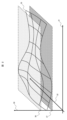
- FIG. FIG. 4 is a diagram showing an example of a graph for calculating a prohibition weather condition and a reportable weather condition according to the first embodiment.
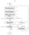
- 4 is a flowchart showing a processing flow of the flight path generation device according to the first embodiment.
- aircraft includes aircraft such as passenger planes, helicopters, and unmanned aerial vehicles known as drones.
- aircraft such as passenger planes, helicopters, and unmanned aerial vehicles known as drones.
- the flight path generation device 1 is composed of an input unit 10, a weather information extraction unit 11, a flight path generation unit 12, an output unit 13, and a judgment and determination unit 14.
- the input unit 10, the weather information extraction unit 11, the flight path generation unit 12, the output unit 13, and the judgment and determination unit 14 of the flight path generation device 1 are realized by, for example, a processor such as a CPU (not shown), a ROM for storing various programs, a RAM for temporarily storing data in the calculation process, and a storage device such as an external storage device, and the processor such as the CPU reads and executes the various programs stored in the ROM, and stores the calculation results that are the execution results in the RAM or the external storage device.
- the input unit 10, weather information extraction unit 11, flight route generation unit 12, and output unit 13 constituting the flight route generation device 1 are constructed as software on a control computer 22 that performs air traffic control operations
- the judgment unit 14 is constructed as software on an operation management computer 21 that operates the aircraft. Note that this is not limited to the above, and the judgment unit 14 may be configured to be included in the management computer 22.
- An aircraft 20, as an example of an air vehicle, is capable of communicating with an operations management computer 21, for example, by wireless communication using radio waves or light or wired communication using electric wires, and flies along a route instructed by a management unit 23 constructed as software or the like on the operations management computer 21.
- the operation management computer 21 is a flight management device for the aircraft 20 installed by the operator of the aircraft 20, and may be installed, for example, on the fuselage of the aircraft 20 or on the ground.
- the control computer 22 is a management device that generates flight routes for multiple aircraft including the aircraft 20, and may be installed on the ground, for example.
- the weather forecast providing service 24 is, for example, weather forecast data provided by the Japan Meteorological Agency or a private business operator, and can communicate with the flight route generating device 1 via, for example, an Internet line.
- the weather conditions are assumed to be at least one of wind speed, wind direction, wind turbulence intensity, air pressure, temperature, rainfall, snowfall, humidity, etc., but are not limited to these. If there is one, for example, wind speed is preferable. If there are two, wind speed and wind direction are preferable.
- the weather information extraction unit 11 obtains, based on information about the departure point and the arrival point from the input unit 10, weather information about the area around the flight route, which is defined as information about points within a specified distance from a straight line connecting the points, from the weather forecast service 24.
- the flight path generation unit 12 acquires the departure point, destination point, and prohibitive weather conditions from the input unit 10, and weather information around the flight path from the weather information extraction unit 11. Then, it generates a flight path for the aircraft 20 connecting the departure point and destination point so that the flight path for the aircraft 20 does not overlap with flight paths generated for other aircraft, and so that there are no areas on the flight path that fall under the prohibitive weather conditions.
- the output unit 13 acquires the flight path of the aircraft 20 and weather information along the flight path from the flight path generation unit 12, and also acquires the reported meteorological conditions from the input unit 10. It then outputs the flight path to the determination unit 14, and if there is a reported area on the flight path of the aircraft 20 that is an area that includes the reported meteorological conditions, it outputs the reported area and the weather information for the reported area together to the determination unit 14.
- the determination unit 14 obtains the flight path, the notification area, and the notification area weather information from the output unit 13, and based on this information, calculates the flight method for the aircraft 20 to fly the flight path. If it determines that flight is possible, it commands the aircraft 20 to fly using that flight method via the management unit 23. On the other hand, if it determines that flight is impossible, it requests the input unit 10 to regenerate the flight path via the management unit 23. At this time, the determination unit 14 may include the weather conditions of the area where flight was impossible in the prohibited weather conditions, or may add new waypoints and request the generation of multiple flight paths with the waypoints as departure and destination points to avoid the area.
- FIG. 2 is a conceptual diagram showing a graph for calculating the prohibitive weather conditions and the notifiable weather conditions according to this embodiment. It is assumed that the weather conditions under which the aircraft 20 can fly are indicated based on a wide variety of conditions by the manufacturer of the aircraft, etc., but are shown here as a schematic diagram by evaluation axes 30 to 32, and the boundary between the weather conditions under which the aircraft 20 can fly and the conditions under which the aircraft 20 cannot fly is indicated by a curved surface 35. Also, it is assumed that the only weather condition that can be input to the input unit 10 is the evaluation axis 30.
- the evaluation axis 30 is the maximum wind speed
- the evaluation axis 31 is the wind direction for the aircraft 20, which is the flying object
- the evaluation axis 32 is the payload of the aircraft 20.
- the judgment unit 14 stores the graph (map) shown in FIG. 2 in a memory unit not shown.
- the prohibitive weather condition is, for example, a condition that can be input to the input unit 10, and is defined as a sufficient condition for the condition under which the aircraft 20 cannot fly. That is, for example, the condition "evaluation axis 30 is equal to or greater than value 36", which indicates the area above value 36, which is the maximum value when the curved surface 35 is projected onto the evaluation axis 30 in Fig. 2, indicates a condition under which flight is impossible regardless of the values of the other evaluation axes 31 and 32, and therefore can be a prohibitive weather condition.
- the reported weather conditions are conditions that can be input to the input unit 10, for example, and are defined as necessary conditions for the aircraft 20 to be unable to fly.
- the condition "evaluation axis 30 is equal to or greater than value 37" which indicates the area above value 37, which is the minimum value when curved surface 35 is projected onto evaluation axis 30 in Figure 2, can be a weather condition to be reported, because in the area where evaluation axis 30 is equal to or greater than value 37 and equal to or less than value 36, it includes cases where flight is impossible and cases where flight is possible depending on the values of evaluation axis 31 and evaluation axis 32.
- the flight path generation unit 12 is capable of generating a flight path that takes into account only the wind speed of the environment in which the aircraft 20 flies, and therefore that only the maximum wind speed at which the aircraft can fly can be input to the input unit 10.
- aircraft 20 with fixed wings have high wind resistance because they have static stability when it comes to winds from the front of the aircraft, but the fixed wings tend to act in a direction that impairs the stability of the aircraft when it comes into contact with crosswinds or tailwinds, and therefore it is expected that wind resistance will decrease in crosswind or tailwind environments.
- the acceleration caused by the wind on the aircraft 20 is proportional to the force it receives from the wind and inversely proportional to its weight, but the force that the aircraft 20 receives from the wind is determined by the shape of the aircraft and is not affected by the payload. Therefore, it is generally expected that the lighter the payload of an aircraft, the lower its wind resistance will be.
- the weather conditions related to winds under which the aircraft 20 can fly can be defined as a curved surface 35a showing the maximum wind speed 30a under which the aircraft can fly according to each parameter, using the wind direction 32a relative to the nose and the load weight 31a as parameters, as shown in Figure 3.
- the curved surface 35a is maximum when the wind direction 32a is 0 degrees, and at the same time, when the wind direction 32a is constant, the curved surface increases monotonically as the load weight 31a increases.
- the management unit 23 first transmits to the input unit 10 a value 36a, which is a weather condition that can be input to the input unit 10 as a prohibitive weather condition and is a sufficient condition for the condition that makes the aircraft 20 unable to fly, and a value 37a, which is a weather condition that can be input to the input unit 10 as a notifiable weather condition and is a necessary condition for the condition that makes the aircraft 20 unable to fly, together with the departure point and destination point of the aircraft 20.
- a value 36a which is a weather condition that can be input to the input unit 10 as a prohibitive weather condition and is a sufficient condition for the condition that makes the aircraft 20 unable to fly
- a value 37a which is a weather condition that can be input to the input unit 10 as a notifiable weather condition and is a necessary condition for the condition that makes the aircraft 20 unable to fly
- the weather information extraction unit 11 based on the information about the departure point and the arrival point acquired from the input unit 10, acquires weather information including wind direction, wind speed, etc. of points within a specified distance from a straight line connecting the points from the weather forecast providing service 24 as weather information around the flight route.
- the flight path generation unit 12 acquires the departure point, destination point, and prohibited weather conditions from the input unit 10.
- the flight path generation unit 12 also acquires weather information around the flight path from the weather information extraction unit 11. Then, the flight path generation unit 12 generates a flight path for the aircraft 20 connecting the departure point and the destination point so that the flight path for the aircraft 20 does not overlap with flight paths generated for other aircraft and so that no area corresponding to the prohibited weather conditions exists on the flight path.
- the output unit 13 acquires the flight path of the aircraft 20 and weather information along the flight path from the flight path generation unit 12, and the reported meteorological conditions from the input unit 10. It then outputs the flight path to the determination unit 14, and if there is a reported area on the flight path of the aircraft 20 that is an area that includes the reported meteorological conditions, it outputs the reported area and the weather information for the reported area to the determination unit 14.
- the determination unit 14 obtains the flight path, the report area, and the report area weather information from the output unit 13, calculates the wind direction and wind speed when flying in the report area from the flight path heading and the report weather area information, calculates the load weight when flying in the report weather area from the flight path information and the remaining fuel of the aircraft, and plots the wind direction and load weight on the wind resistance characteristics of Figure 3. Then, for example, when the conditions when flying in the report area correspond to the conditions where flight is possible, such as point 40a, the determination unit 14 commands the aircraft 20 to fly the flight path through the management unit 23. Also, when the conditions when flying correspond to the conditions where flight is impossible, such as point 40b, the determination unit 14 requests the input unit 10 to regenerate the flight path through the management unit 23.
- the judgment unit 14 may set the value 38a corresponding to the weather conditions of the area where flight was previously impossible as a new prohibited weather condition, or may request the generation of multiple flight routes by adding new waypoints and using the waypoints as departure and destination points in order to avoid the area.
- FIG. 4 is a flowchart showing a processing flow of the flight path generation device according to the present embodiment.
- the input unit 10 inputs, from the management unit 23, the departure point and destination point of the aircraft 20 as an air vehicle, prohibited weather conditions indicating weather conditions under which flight is impossible, and reported weather conditions indicating weather conditions under which the aircraft 20 may be unable to fly (in other words, difficult to fly).
- the weather information extraction unit 11 acquires, based on the information on the departure point and destination point from the input unit 10, weather information for the vicinity of the flight route, which is defined as information on points within a specified distance from a straight line connecting the points, from the weather forecast providing service 24.
- the flight path generation unit 12 acquires the departure point, destination point, and prohibited weather conditions from the input unit 10. It also acquires weather information around the flight path from the weather information extraction unit 11. Then, it generates a flight path for the aircraft 20 connecting the departure point and the destination point so that the flight path for the aircraft 20 does not overlap with flight paths generated for other aircraft and so that there are no areas on the flight path that fall under prohibited weather conditions.
- step S14 the judgment unit 14 obtains the flight path, the report area, and the weather information for the report area from the output unit 13, and calculates the flight method for the aircraft 20 to fly the flight path based on this information.
- the judgment unit 14 determines whether there is a report area on the calculated flight path that is an area containing reportable meteorological conditions. If the result of the determination is that there is a report area on the flight path, the process proceeds to step S15, and the flight path, the report meteorological area, and the report meteorological conditions are output to the management unit 23. On the other hand, if the result of the determination is that there is no report area on the flight path, the process proceeds to step S16, and the judgment unit 14 outputs the flight path to the management unit 23.
- step S17 the judgment unit 14 judges whether flight is possible based on the output information. If the judgment result shows that flight is possible, the process ends. On the other hand, if the judgment result shows that flight is not possible, the process proceeds to step S18, and a request is made to the input unit 10 via the management unit 23 to regenerate the flight path. Specifically, the prohibited flight conditions are changed and/or the flight path is changed, and the process returns to step S11 and the above-mentioned process is repeated.
- the flight path generation unit 12 acquires the departure point, destination point, and prohibited weather conditions as well as the reported weather conditions from the input unit 10, and generates a flight path connecting the departure point and destination point so that the flight path of the aircraft 20 does not overlap with flight paths generated for other aircraft and so that there are no areas on the flight path that fall under the prohibited weather conditions and the reported weather conditions. Only if it is impossible to generate such a path, may the flight path generation unit 12 generate a flight path that includes areas that fall under the reported weather conditions.
- the input unit 10 when the input unit 10 acquires the prohibited weather conditions and the notifiable weather conditions, it may acquire a plurality of prohibited weather conditions and the notifiable weather conditions according to route parameters that affect the weather resistance performance of the aircraft, such as ground altitude and ground speed, and the flight route generation unit 12 and the output unit 13 may refer to the relevant prohibited conditions and notifiable weather conditions according to the above parameters on the flight route.
- the weather conditions and notifiable weather conditions corresponding to the ground altitude and ground speed being below a specified value, which corresponds to takeoff and landing when wind resistance is reduced may be set to be strict
- the weather conditions and notifiable weather conditions corresponding to the ground altitude and ground speed being above a specified value, which corresponds to cruising when wind resistance is relatively high may be set to be relaxed.
- the judgment unit 14 may output the proposed flight path to the input unit 10, and the flight path generation unit 12 may be configured to obtain the proposed flight path from the input unit 10 and generate a flight path based on the proposed flight path.
- the judgment unit 14 judges that flight is impossible along the flight path output by the output unit 13, it outputs information about the impossible flight area, which is the area judged to be impossible to fly, to the input unit 10, and the flight path generation unit 12 may be configured to obtain the impossible flight area from the input unit 10 and generate a flight path so that the impossible flight area is not included on the path.
- the evaluation axes are three, 30 to 32, and the weather conditions that can be input to the input unit 10 are one, evaluation axis 30, but the number of evaluation axes is not limited to this example, and the weather conditions are not limited to them.
- the number of evaluation axes is not limited to this example, and the weather conditions are not limited to them.
- this embodiment makes it possible to provide a flight path generation device and a flight path generation method that appropriately consider the weather resistance performance of a wide variety of flying objects and generate safe flight paths.
- users of the flight route generation device such as aircraft dispatchers, can obtain flight routes that appropriately take into account the weather resistance performance of the aircraft, without being limited by the constraints of the communication paths between computers or the weather conditions that the input unit and flight route generation unit can process.
- the weather conditions and reported weather conditions corresponding to the ground altitude and ground speed being below a specified value, which corresponds to takeoff and landing when wind resistance is reduced are set to be strict, while the weather conditions and reported weather conditions corresponding to the ground altitude and ground speed being above a specified value, which corresponds to cruising when wind resistance is relatively high, are relaxed, thereby reducing the reported weather area and reported weather conditions output by the output unit 13, and thus reducing the processing load of the judgment unit 14 and the frequency with which the judgment unit 14 judges that flight is impossible and requests the regeneration of a flight route.
- the flight path generation unit when the flight path generation unit generates a path that the aircraft 20 cannot fly, it is possible to efficiently regenerate a path that the aircraft 20 can fly.
- the judgment unit 14 judges that flight is impossible along the flight path output by the output unit 13, it outputs information about the impossible area, which is the area judged to be impossible to fly, to the input unit 10, and the flight path generation unit 12 acquires the impossible area from the input unit 10 and generates a flight path so that the impossible area is not included on the path.
- This makes it possible to efficiently regenerate a path along which the aircraft 20 can fly when the flight path generation unit generates an impossible path for the aircraft 20.
Landscapes
- Engineering & Computer Science (AREA)
- Radar, Positioning & Navigation (AREA)
- Remote Sensing (AREA)
- Aviation & Aerospace Engineering (AREA)
- Physics & Mathematics (AREA)
- General Physics & Mathematics (AREA)
- Automation & Control Theory (AREA)
- Mechanical Engineering (AREA)
- Traffic Control Systems (AREA)
- Navigation (AREA)
Abstract
多種多様な飛行体に対して、飛行体の耐気象性能を適切に考慮し、安全な飛行経路を生成する飛行経路生成装置及び飛行経路生成方法を提供する。 飛行経路生成装置1は、飛行体20の飛行不可能な気象条件を示す禁止気象条件、飛行体20の飛行困難な気象条件を示す報知気象条件、飛行体20の出発地点、及び飛行体20の目的地点と、を入力する入力部10と、入力される禁止気象条件と報知気象条件とに基づき、飛行体20の飛行経路の飛行可否を判断する判断部14と、判断部の判断結果に応じて、気象情報と前記禁止気象条件とに基づき、飛行体20の飛行経路に、前記禁止気象条件を含む領域を含まぬよう飛行経路を生成する飛行経路生成部12と、を有する。
Description
本発明は、耐気象性能について考慮が必要な飛行体の飛行経路を生成する飛行経路生成装置及び飛行経路生成方法に関する。
従来、航空機に対する管制業務は、例えば管制官が管制空域の気象情報や空域を飛行する各航空機に関する情報等に基づいて、管制官が思考や判断等を行う。そして、管制官の思考や判断等によって各航空機に対して、当該航空機が飛行可能かつ他機との接触のリスクの低い飛行経路を指示することで行われてきた。しかし今後、無人航空機の普及に伴って航空機の交通量が増加した場合、現行の管制業務のままでは管制官の負担が増大して、安全な管制業務に支障が生じることが懸念される。また、さらに無人航空機は一般的に人を積載する必要が無いことから小型軽量かつ、多種多様な飛行形態および特性を有したものであることが多く、その耐風性能をはじめとする耐気象性能は従来の航空機よりも低く、かつ飛行形態や風向等をはじめとする、多種多様なパラメータによって規定されることが予想される。そのため、従来のように管制官が気象情報と航空機の諸元を元に適切な飛行経路を指示することは困難となることが予想される。
このような、耐気象性能を考慮した効率的な飛行経路生成という課題に対し、例えば特許文献1では、空域上の各地点について、当該地点を航空機が飛行可能な気象条件を取得する条件情報取得部と、与えられた飛行経路上の気象情報を取得する気象情報取得部を有し、上記気象条件と上記気象情報を比較することで、飛行経路の飛行可否を判断する運行管理装置を提案している。
航空機の管制業務においては、各航空機に指示する飛行経路について、当該飛行経路上の気象が、各航空機が飛行可能な気象条件を満たすように飛行経路の生成を行うことが求められる。この際、各航空機が飛行可能な気象条件を過小に評価した場合、航空機の就航率の低下を、過大に評価した場合、航空機の安全性が低下するため、航空機の飛行可能な気象条件を過不足なく評価した飛行経路生成が求められる。また、あわせて当該飛行経路は他の航空機の飛行経路と接触するリスクが低く、かつ飛行時間・運行密度の観点から効率的な経路であることが求められる。
本観点において、例えば特許文献1の手法によれば、当該飛行管理装置が管制下にある航空機の飛行経路を生成する飛行経路生成装置に組み込まれ、条件情報取得部が、管制対象となる機体の飛行不可能な気象条件を取得することで、気象条件の制約を考慮した飛行経路の生成が可能となる。
しかしながらこの際、多種多様なパラメータによって規定されうる航空機の飛行可能な気象条件を、飛行管理装置が受け入れ可能なパラメータとして事前に規定することは困難である。したがって、当該気象条件を飛行管理装置に伝達し、かつ飛行経路生成装置の内部で考慮することは困難である。例えば、ある航空機の飛行可能な気象条件が最大風速と風向の2つのパラメータによって規定されており、特定の風向以外では最大風速10m/sまでの風のなかで飛行可能であるが、特定の風向では最大風速5m/sの風で不安定化するリスクがある場合を仮定する。また一方、上記条件情報取得部は多種多様な機体に共通のパラメータとして、最大風速のみが規定可能であったと仮定する。この際、上記条件情報取得部に上記航空機が飛行可能な最大風速を5m/sとして登録を行うと、実際には飛行可能な気象であっても飛行経路が生成できないために運行密度が低下するリスクが生ずる。また、上記条件情報取得部に上記航空機が飛行可能な最大風速を10m/sとして登録を行うと、運行密度は向上するが、上記特定の風向から10m/sの風があたり、当該機体が不安定化するリスクが生じ得る。
したがって、特許文献1の手法では、多種多様な航空機の飛行可能な気象条件を過不足なく考慮することは困難であり、過大に飛行可能な気象条件を考慮した結果、空域の利用効率の低下を招き、また、過小に飛行可能な気象条件を考慮した結果、危険な飛行経路を生成するリスクが生じ得る。
したがって、特許文献1の手法では、多種多様な航空機の飛行可能な気象条件を過不足なく考慮することは困難であり、過大に飛行可能な気象条件を考慮した結果、空域の利用効率の低下を招き、また、過小に飛行可能な気象条件を考慮した結果、危険な飛行経路を生成するリスクが生じ得る。
そこで、本発明は、多種多様な飛行体に対して、飛行体の耐気象性能を適切に考慮し、安全な飛行経路を生成する飛行経路生成装置及び飛行経路生成方法を提供する。
上記課題を解決するため、本発明に係る飛行経路生成装置は、飛行体の飛行経路を生成する飛行経路生成装置であって、前記飛行体の飛行不可能な気象条件を示す禁止気象条件と、前記飛行体の飛行困難な気象条件を示す報知気象条件と、前記飛行体の出発地点と、前記飛行体の目的地点と、を入力する入力部と、入力される前記禁止気象条件と前記報知気象条件とに基づき、飛行体の飛行経路の飛行可否及び新たな飛行経路の必要性を判断する判断部と、前記判断部の判断結果に応じて、気象情報と前記禁止気象条件とに基づき、前記飛行体の飛行経路に、前記禁止気象条件を含む領域を含まぬよう飛行経路を生成する飛行経路生成部と、を有することを特徴とする。
また、本発明に係る飛行経路生成方法は、飛行体の飛行経路を生成する飛行経路生成方法であって、入力部が、前記飛行体の飛行不可能な気象条件を示す禁止気象条件と、前記飛行体の飛行困難な気象条件を示す報知気象条件と、前記飛行体の出発地点と、前記飛行体の目的地点と、を入力し、判断部が、入力される前記禁止気象条件と前記報知気象条件とに基づき、前記飛行体の飛行経路の飛行可否及び新たな飛行経路の必要性を判断し、飛行経路生成部が、前記判断部の判断結果に応じて、気象情報と前記禁止気象条件とに基づき、前記飛行体の飛行経路に、前記禁止気象条件を含む領域を含まぬよう飛行経路を生成することを特徴とする。
本発明によれば、多種多様な飛行体に対して、飛行体の耐気象性能を適切に考慮し、安全な飛行経路を生成する飛行経路生成装置及び飛行経路生成方法を提供することが可能となる。
上記した以外の課題、構成及び効果は、以下の実施形態の説明により明らかにされる。
上記した以外の課題、構成及び効果は、以下の実施形態の説明により明らかにされる。
本明細書において「飛行体」とは、旅客機などの航空機、ヘリコプター、及び所謂ドローンと称される無人航空機を含む。
以下では、飛行体の一例として航空機による場合の本発明の実施例について、図面を用いて説明する。
以下では、飛行体の一例として航空機による場合の本発明の実施例について、図面を用いて説明する。
図1は、本発明の実施例1に係る飛行経路生成装置の全体概略構成図である。飛行経路生成装置1は、入力部10、気象情報抽出部11、飛行経路生成部12、出力部13、判及び判断部14にて構成される。ここで、飛行経路生成装置1は、入力部10、気象情報抽出部11、飛行経路生成部12、出力部13、判及び判断部14は、例えば、図示しないCPUなどのプロセッサ、各種プログラムを格納するROM、演算過程のデータを一時的に可能するRAM、外部記憶装置などの記憶装置にて実現されると共に、CPUなどのプロセッサがROMに格納された各種プログラムを読み出し実行し、実行結果である演算結果をRAM又は外部記憶装置に格納する。
例えば、飛行経路生成装置1を構成する、入力部10、気象情報抽出部11、飛行経路生成部12、及び出力部13は、管制業務を行う管制コンピュータ22上に、判断部14は機体の運行を行う運行管理コンピュータ21上にソフトウェアとして構築される。なお、これに限られず、判断部14を管理コンピュータ22が有する構成としてもよい。
例えば、飛行経路生成装置1を構成する、入力部10、気象情報抽出部11、飛行経路生成部12、及び出力部13は、管制業務を行う管制コンピュータ22上に、判断部14は機体の運行を行う運行管理コンピュータ21上にソフトウェアとして構築される。なお、これに限られず、判断部14を管理コンピュータ22が有する構成としてもよい。
飛行体の一例としての航空機20は、例えば電波や光を用いた無線通信や電線を用いた有線通信によって運行管理コンピュータ21と通信可能であり、運行管理コンピュータ21上にソフトウェア等として構築された管理部23から指示された経路にて飛行を行う。
運行管理コンピュータ21は、航空機20の運行者によって設置された航空機20の飛行管理装置であり、例えば航空機20の機体上又は地上に設置されることが考えられる。
管制コンピュータ22は、航空機20をはじめとする複数の航空機に対して飛行経路の生成を行う管理装置であり、例えば地上に設置されることが考えられる。気象予測提供サービス24は、例えば気象庁の提供する気象予測データや、民間事業者によって提供される気象予測データであり、例えばインターネット回線を通して飛行経路生成装置1と通信可能である。
運行管理コンピュータ21は、航空機20の運行者によって設置された航空機20の飛行管理装置であり、例えば航空機20の機体上又は地上に設置されることが考えられる。
管制コンピュータ22は、航空機20をはじめとする複数の航空機に対して飛行経路の生成を行う管理装置であり、例えば地上に設置されることが考えられる。気象予測提供サービス24は、例えば気象庁の提供する気象予測データや、民間事業者によって提供される気象予測データであり、例えばインターネット回線を通して飛行経路生成装置1と通信可能である。
航空機20の運行を管理する管理部23は、航空機20の出発地点と目的地点と飛行不可能な気象条件を示す禁止気象条件と、航空機20が飛行不可能である可能性を有する(換言すれば、飛行困難な)気象条件を示す報知気象条件とを、入力部10に送信する。
ここで、気象条件には風速、風向、風の乱流強度、気圧、気温、降雨量、降雪量、湿度などのうち少なくとも1つが想定されるが、これに限られるものではない。仮に1つの場合、例えば、風速が望ましい。また、仮に2つの場合は、風速及び風向が望ましい。
ここで、気象条件には風速、風向、風の乱流強度、気圧、気温、降雨量、降雪量、湿度などのうち少なくとも1つが想定されるが、これに限られるものではない。仮に1つの場合、例えば、風速が望ましい。また、仮に2つの場合は、風速及び風向が望ましい。
気象情報抽出部11は、入力部10から上記出発地と上記到着地に関する情報に基づき、例えば、当該地点を結ぶ直線から規定の距離以内の地点の情報として定義される、飛行経路周辺の気象情報を気象予測提供サービス24から取得する。
飛行経路生成部12は、入力部10から上記出発地点と上記目的地点と上記禁止気象条件を、気象情報抽出部11から飛行経路周辺の気象情報を取得する。そして、航空機20の飛行経路を、他の航空機に生成した飛行経路と重複せず、且つ飛行経路上に上記禁止気象条件に該当する領域が存在せぬよう、出発地点と目的地点を結ぶ航空機20の飛行経路の生成を行う。
出力部13は、飛行経路生成部12から航空機20の飛行経路と飛行経路上の気象情報を取得すると共に、入力部10から報知気象条件を取得する。そして、上記飛行経路を判断部14に出力すると共に、航空機20の飛行経路上に、上記報知気象条件を含む領域である報知領域がある場合、報知領域と報知領域の気象情報である報知領域気象情報をあわせて判断部14に出力する。
判断部14は、出力部13から、上記飛行経路と上記報知領域と上記報知領域気象情報を取得し、これらの情報に基づき、航空機20が上記飛行経路を飛行する際の飛行方法を算出し、飛行可能であると判断した場合は、管理部23を通じて当該飛行方法にて飛行するよう航空機20に指令する。一方、飛行不可能であると判断した場合には、管理部23を通じて入力部10に飛行経路の再生成を要求する。この際、判断部14は、飛行不可能であった領域の気象条件を禁止気象条件に含めたり、当該領域を回避するよう、新たに経由点を加えて経由点を出発地点及び目的地点とした複数の飛行経路の生成を要求することが考えられる。
ここで、禁止気象条件及び報知気象条件について図2を用いて示す。図2は本実施例に係る禁止気象条件及び報知気象条件を算出するためのグラフを示す概念図である。航空機20が飛行可能な気象条件は、機体の製造者等によって多種多様な条件を元に示されることが想定されるが、ここでは模式的に評価軸30~32で示され、航空機20が飛行可能な気象条件と飛行不可能な条件の境界が曲面35で示されているものとする。また、入力部10に入力可能な気象条件は評価軸30のみであるとする。例えば、評価軸30は最大風速、評価軸31は飛行体である航空機20の機体にとっての風向、評価軸32は航空機20の積載重量である。但し、これらに限られるものではなく、各種飛行モード、バッテリー残量、積載物に許容される振動又は動揺などでもよい。判断部14が図示しない記憶部にこの図2に示すグラフ(マップ)を格納している。
ここで、禁止気象条件は、例えば入力部10に入力可能な条件であって、航空機20が飛行不可能な条件に対する十分条件として定義される。すなわち、例えば図2において評価軸30に曲面35を投影した際の最大値である値36より上の領域を示す、「評価軸30が値36以上」という条件が、他の評価軸31と評価軸32の値によらず飛行不可能となる条件を示すため、禁止気象条件となりうる。
また、報知気象条件は、例えば入力部10に入力可能な条件であって、航空機20が飛行不可能な条件に対する必要条件として定義される。
すなわち、例えば図2において評価軸30に曲面35を投影した際の最小値である値37より上の領域を示す、「評価軸30が値37以上」という条件が、評価軸30が値37以上値36以下の領域において、評価軸31と評価軸32の値によって飛行不可能な場合と飛行可能な場合を含むことになるため、報知気象条件となりうる。
また、報知気象条件は、例えば入力部10に入力可能な条件であって、航空機20が飛行不可能な条件に対する必要条件として定義される。
すなわち、例えば図2において評価軸30に曲面35を投影した際の最小値である値37より上の領域を示す、「評価軸30が値37以上」という条件が、評価軸30が値37以上値36以下の領域において、評価軸31と評価軸32の値によって飛行不可能な場合と飛行可能な場合を含むことになるため、報知気象条件となりうる。
ここで、具体的な事例を以下に示す。
例えば、航空機20は固定翼を有するとともに、内燃機関で飛行を行うために燃料の消費に伴って飛行中に積載重量が変化する機体であったとする。また、飛行経路生成部12は航空機20が飛行する環境の風速のみを考慮した飛行経路生成が可能であり、したがって入力部10には航空機の飛行可能な最大風速のみを入力可能であったとする。
例えば、航空機20は固定翼を有するとともに、内燃機関で飛行を行うために燃料の消費に伴って飛行中に積載重量が変化する機体であったとする。また、飛行経路生成部12は航空機20が飛行する環境の風速のみを考慮した飛行経路生成が可能であり、したがって入力部10には航空機の飛行可能な最大風速のみを入力可能であったとする。
一般的に固定翼を有する航空機20は、機体正面からの風に対しては静安定性を有するために耐風性が高い一方で、横風や背風に対しては固定翼が機体の安定性を損なう方向に働きやすく、したがって横風や背風環境下では耐風性能が低下することが想定される。また、風によって航空機20に生じる加速度は慣性の法則より、風から受ける力に比例し、重量に反比例するが、航空機20が風から受ける力は機体の形状によって決まり、積載重量の影響を受けない。そのため、一般的に航空機は積載重量が軽いほど、耐風性能が低下することが想定される。
これらの事情に鑑みると、例えば航空機20の飛行可能な風に関する気象条件は,図3のように機首に対する風向32aと積載重量31aをパラメータとして、各パラメータに応じた飛行可能な最大風速30aを示す曲面35aとして規定されることが考えられる。
ここで、曲面35aは積載重量31aを一定とした場合、風向32aが0度の時極大となると同時に、風向32aを一定とした場合、積載重量31aの増加に対して単調増加となる曲面となっている。
ここで、曲面35aは積載重量31aを一定とした場合、風向32aが0度の時極大となると同時に、風向32aを一定とした場合、積載重量31aの増加に対して単調増加となる曲面となっている。
この時、まず管理部23は、禁止気象条件として、入力部10に入力可能な気象条件であって、航空機20の飛行不可能な条件に対する十分条件である値36aを、報知気象条件として入力部10に入力可能な気象条件であって、航空機20の飛行不可能な条件に対する必要条件である値37aを、航空機20の出発地点と目的地点と共に、入力部10に送信する。
気象情報抽出部11は、入力部10から取得した前記出発地と前記到着地に関する情報を元に、当該地点間を結ぶ直線から規定の距離以内の地点の風向・風速等を含む気象情報を、飛行経路周辺の気象情報として気象予測提供サービス24から取得する。
飛行経路生成部12は、入力部10から上記出発地点、上記目的地点、及び禁止気象条件を取得する。また、飛行経路生成部12は、気象情報抽出部11から飛行経路周辺の気象情報を取得する。そして、航空機20の飛行経路を、他の航空機に生成した飛行経路と重複せず、かつ飛行経路上に上記禁止気象条件に該当する領域が存在せぬよう、出発地点と目的地点を結ぶ航空機20の飛行経路の生成を行う。
出力部13は、飛行経路生成部12から航空機20の飛行経路と飛行経路上の気象情報を、入力部10から報知気象条件を取得する。そして、上記飛行経路を判断部14に出力すると共に、航空機20の飛行経路上に、上記報知気象条件を含む領域である報知領域がある場合、報知領域と報知領域の気象情報である報知領域気象情報をあわせて判断部14に出力する。
判断部14は、出力部13から、上記飛行経路、上記報知領域、及び上記報知領域気象情報を取得し、飛行経路の針路と上記報知気象領域情報から、前記報知領域を飛行する際の風向・風速を、飛行経路の情報と自機の燃料残量から報知気象領域を飛行する際の積載重量を算出し、当該風向と積載重量を図3の耐風特性にプロットする。そして、例えば報知領域を飛行する際の条件が点40aのように飛行可能な条件に該当する場合には、当該飛行経路を飛行するよう管理部23を通じて航空機20に指令する。また、例えば飛行する際の条件が点40bのように飛行不可能な条件に該当する場合には、管理部23を通じて入力部10に飛行経路の再生成を要求する。
この際、判断部14は、飛行不可能であった領域の気象条件に該当する値38aを新たに禁止気象条件としたり、当該領域を回避するよう、新たに経由点を加えて経由点を出発地点及び目的地点とした複数の飛行経路の生成を要求することが考えられる。
この際、判断部14は、飛行不可能であった領域の気象条件に該当する値38aを新たに禁止気象条件としたり、当該領域を回避するよう、新たに経由点を加えて経由点を出発地点及び目的地点とした複数の飛行経路の生成を要求することが考えられる。
図4は、本実施例に係る飛行経路生成装置の処理フローを示すフローチャートである。
図4に示すように、ステップS11では、入力部10が、管理部23より、飛行体としての航空機20の出発地点と目的地点と飛行不可能な気象条件を示す禁止気象条件と、航空機20が飛行不可能である可能性を有する(換言すれば、飛行困難な)気象条件を示す報知気象条件とを入力する。ステップS12では、気象情報抽出部11が、入力部10から出発地点と目的地点に関する情報に基づき、例えば、当該地点を結ぶ直線から規定の距離以内の地点の情報として定義される、飛行経路周辺の気象情報を気象予測提供サービス24から取得する。
図4に示すように、ステップS11では、入力部10が、管理部23より、飛行体としての航空機20の出発地点と目的地点と飛行不可能な気象条件を示す禁止気象条件と、航空機20が飛行不可能である可能性を有する(換言すれば、飛行困難な)気象条件を示す報知気象条件とを入力する。ステップS12では、気象情報抽出部11が、入力部10から出発地点と目的地点に関する情報に基づき、例えば、当該地点を結ぶ直線から規定の距離以内の地点の情報として定義される、飛行経路周辺の気象情報を気象予測提供サービス24から取得する。
ステップS13では、飛行経路生成部12が、入力部10から出発地点、目的地点、及び禁止気象条件を取得する。また、気象情報抽出部11から飛行経路周辺の気象情報を取得する。そして、航空機20の飛行経路を、他の航空機に生成した飛行経路と重複せず、且つ飛行経路上に禁止気象条件に該当する領域が存在せぬよう、出発地点と目的地点を結ぶ航空機20の飛行経路を生成する。
ステップS14では、判断部14が、出力部13から、飛行経路と報知領域と上記報知領域気象情報を取得し、これらの情報に基づき、航空機20が上記飛行経路を飛行する際の飛行方法を算出する。そして、判断部14が、算出した飛行経路上に報知気象条件を含む領域である報知領域があるか判定する。判定の結果、飛行経路上に報知領域がある場合はステップS15へ進み、飛行経路、報知気象領域、報知気象条件を管理部23へ出力する。一方、判定の結果、飛行経路上に報知領域がない場合はステップS16へ進み、判断部14が管理部23へ飛行経路を出力する。
ステップS17では、判断部14が、出力された情報に基づき飛行可否を判断する。判断の結果、飛行可能であれば処理を終了する。一方、判断の結果、飛行不可能であればステップS18へ進み、管理部23を通じて入力部10に飛行経路の再生成を要求する。具体的には、禁止飛行条件の変更や、飛行経路の変更を実施しステップS11へ戻り上述の処理を繰り返し実行する。
本実施例において、飛行経路生成部12は、入力部10から出発地点と目的地点と禁止気象条件に加えて、報知気象条件を取得し、航空機20の飛行経路を、他の航空機に生成した飛行経路と重複せず、かつ飛行経路上に禁止気象条件と報知気象条件に該当する領域が存在しないよう、出発地点と目的地点を結ぶ飛行経路の生成を行い、当該経路の生成が不可能な場合のみ、報知気象条件に該当する領域を含む飛行経路の生成を行ってもよい。
また、本実施例において、入力部10は禁止気象条件及び報知気象条件を取得する際、例えば対地高度や対地速度などの、機体の耐気象性能に影響を与える経路パラメータに応じて、複数の禁止気象条件及び前記報知条件の取得を行い、飛行経路生成部12及び出力部13は飛行経路上の上記パラメータに応じて、該当する禁止条件と、報知気象条件を参照する構成としても良い。本発明によれば、例えば耐風性能が低下する離着陸中に相当する、対地高度や対地速度が規定値以下の場合に対応する気象条件及び報知気象条件を厳しく設定し、一方で比較的耐風性能の高い巡航中に相当する、対地高度や対地速度が規定値以上の場合に対応する気象条件及び報知気象条件を緩和する構成としても良い。これにより、例えば耐風性能が低下する離着陸中に相当する、対地高度や対地速度が規定値以下の場合に対応する気象条件及び報知気象条件を厳しく設定し、一方で比較的耐風性能の高い巡航中に相当する、対地高度や対地速度が規定値以上の場合に対応する気象条件及び報知気象条件を緩和することで、出力部13が出力する報知気象領域及び報知気象条件を低減し、ひいては判断部14の処理負荷や、判断部14が飛行不可能と判定し、飛行経路の再生成を要求する頻度を低減することが可能となる。
本実施例において、判断部14は出力部13より出力された飛行経路上での飛行が不可能であると判断した場合に、当該飛行経路を修正して飛行可能な提案飛行経路を生成可能な場合、提案飛行経路を入力部10に出力し、飛行経路生成部12は提案飛行経路を入力部10から取得して、提案飛行経路に基づき飛行経路を生成する構成としていても良い。
また、本実施例において、判断部14は出力部13より出力された飛行経路上での飛行が不可能であると判断した場合に、飛行不可能と判断した領域である飛行不可能領域の情報を入力部10に出力し、飛行経路生成部12は飛行不可能領域を入力部10から取得して、飛行不可能領域を経路上に含まないよう、飛行経路を生成する構成としても良い。
本実施例では評価軸は30~32の3軸、入力部10に入力可能な気象条件は評価軸30の1軸として説明したが、これらの評価軸の本数は本例に限られるものではなく、また気象条件に限定されるものではない。例えば、評価軸に機体重量を規定し、当該航空機の飛行中に燃料消費等によって想定される機体重量範囲について評価を行うことで、飛行中の重量変化を考慮した飛行経路の生成が可能となる。
以上の通り本実施例によれば、多種多様な飛行体に対して、飛行体の耐気象性能を適切に考慮し、安全な飛行経路を生成する飛行経路生成装置及び飛行経路生成方法を提供することが可能となる。
更に、本実施例によれば、多種多様な飛行体に対して、飛行体の耐気象性能を適切に考慮し、他の飛行体との接触リスクが低く且つ効率的な飛行経路を生成する飛行経路生成装置及び飛行経路生成方法を提供することが可能となる。
また、本実施例によれば、各航空機の運航管理者などの飛行経路生成装置利用者は、コンピュータ間の通信路や入力部および飛行経路生成部が処理可能な気象条件の制約に限定されることなく、航空機の耐気象性能を適切に考慮した飛行経路の取得が可能となる。
本実施例によれば、出力部13が出力する報知気象領域及び報知気象条件を低減することが可能であり、ひいては判断部14の処理負荷や、判断部14が飛行不可能と判定し、飛行経路の再生成を要求する頻度を低減することが可能となる。
また、本実施例によれば、例えば耐風性能が低下する離着陸中に相当する、対地高度や対地速度が規定値以下の場合に対応する気象条件及び報知気象条件を厳しく設定し、一方で比較的耐風性能の高い巡航中に相当する、対地高度や対地速度が規定値以上の場合に対応する気象条件及び報知気象条件を緩和することで、出力部13が出力する報知気象領域及び報知気象条件を低減し、ひいては判断部14の処理負荷や、判断部14が飛行不可能と判定し、飛行経路の再生成を要求する頻度を低減することが可能となる。
本実施例によれば、飛行経路生成部が航空機20の飛行不可能な経路を生成した際に、効率的に航空機20が飛行可能な経路の再生成が可能となる。
本実施例によれば、判断部14は出力部13より出力された飛行経路上での飛行が不可能であると判断した場合に、飛行不可能と判断した領域である飛行不可能領域の情報を入力部10に出力し、飛行経路生成部12は飛行不可能領域を入力部10から取得して、飛行不可能領域を経路上に含まないよう、飛行経路を生成する。これにより飛行経路生成部が航空機20の飛行不可能な経路を生成した際に、効率的に航空機20が飛行可能な経路の再生成が可能となる。
なお、本発明は上記した実施例に限定されるものではなく、様々な変形例が含まれる。
例えば、上記した実施例は本発明を分かりやすく説明するために詳細に説明したものであり、必ずしも説明した全ての構成を備えるものに限定されるものではない。
例えば、上記した実施例は本発明を分かりやすく説明するために詳細に説明したものであり、必ずしも説明した全ての構成を備えるものに限定されるものではない。
1…飛行経路生成装置
10…入力部
11…気象情報抽出部
12…飛行経路生成部
13…出力部
14…判断部
20…航空機
21…運行管理コンピュータ
22…管制コンピュータ
23…管理部
24…気象予測提供サービス
30,31,32…評価軸
10…入力部
11…気象情報抽出部
12…飛行経路生成部
13…出力部
14…判断部
20…航空機
21…運行管理コンピュータ
22…管制コンピュータ
23…管理部
24…気象予測提供サービス
30,31,32…評価軸
Claims (15)
- 飛行体の飛行経路を生成する飛行経路生成装置であって、
前記飛行体の飛行不可能な気象条件を示す禁止気象条件と、前記飛行体の飛行困難な気象条件を示す報知気象条件と、前記飛行体の出発地点と、前記飛行体の目的地点と、を入力する入力部と、
入力される前記禁止気象条件と前記報知気象条件とに基づき、飛行体の飛行経路の飛行可否を判断する判断部と、
前記判断部の判断結果に応じて、気象情報と前記禁止気象条件とに基づき、前記飛行体の飛行経路に、前記禁止気象条件を含む領域を含まぬよう飛行経路を生成する飛行経路生成部と、を有することを特徴とする飛行経路生成装置。 - 請求項1に記載の飛行経路生成装置において、
前記出発地点と前記目的地点とに基づき、前記飛行体が飛行しうる飛行経路周辺の気象情報を抽出する気象情報抽出部と、
前記気象情報と前記報知気象条件とに基づき、前記飛行体の飛行経路上に、前記報知気象条件を含む領域がある場合、前記報知気象条件を含む領域と前記報知気象条件を含む領域の気象情報である報知領域気象情報を出力する出力部と、を備えることを特徴とする飛行経路生成装置。 - 請求項2に記載の飛行経路生成装置において、
前記飛行経路生成部は、前記飛行体の経路に、前記禁止気象条件と前記報知気象条件を含む領域がないよう飛行経路を出力すると共に、当該飛行経路の生成が困難であった場合にのみ、前記禁止気象条件を含まず、且つ前記報知気象条件を含む飛行経路を出力することを特徴とする飛行経路生成装置。 - 請求項2又は請求項3に記載の飛行経路生成装置において、
前記入力部は、前記禁止気象条件及び前記報知気象条件を取得する際、前記飛行体の機体の耐気象性能に影響を与える経路パラメータに応じた、複数の前記禁止気象条件及び前記報知気象条件の取得し、前記飛行経路生成部及び前記出力部は飛行経路上のパラメータに応じて、該当する前記禁止気象条件と前記報知気象条件を参照することを特徴とする飛行経路生成装置。 - 請求項2又は請求項3項に記載の飛行経路生成装置において、
前記判断部は、前記出力部より出力された飛行経路上での飛行が不可能であると判断した場合に、前記飛行経路を修正して飛行可能な新たな飛行経路として提案飛行経路を生成可能な場合、前記提案飛行経路を前記入力部に出力し、
前記飛行経路生成部は、前記提案飛行経路を前記入力部から取得して、前記提案飛行経路に基づき前記飛行経路を生成することを特徴とする飛行経路生成装置。 - 請求項2又は請求項3に記載の飛行経路生成装置であって、
前記判断部は、前記出力部より出力された飛行経路上での飛行が不可能であると判断した場合に、飛行不可能と判断した領域である飛行不可能領域の情報を前記入力部に出力し、
前記飛行経路生成部は、前記飛行不可能領域を前記入力部から取得して、前記飛行不可能領域を飛行経路上に含まぬよう、前記飛行経路を生成することを特徴とする飛行経路生成装置。 - 請求項4に記載の飛行経路生成装置であって、
前記判断部は、前記出力部より出力された飛行経路上での飛行が不可能であると判断した場合に、飛行不可能と判断した領域である飛行不可能領域の情報を前記入力部に出力し、
前記飛行経路生成部は、前記飛行不可能領域を前記入力部から取得して、前記飛行不可能領域を飛行経路上に含まぬよう、前記飛行経路を生成することを特徴とする飛行経路生成装置。 - 請求項5記載の飛行経路生成装置であって、
前記判断部は、前記出力部より出力された飛行経路上での飛行が不可能であると判断した場合に、飛行不可能と判断した領域である飛行不可能領域の情報を前記入力部に出力し、
前記飛行経路生成部は、前記飛行不可能領域を前記入力部から取得して、前記飛行不可能領域を飛行経路上に含まぬよう、前記飛行経路を生成することを特徴とする飛行経路生成装置。 - 飛行体の飛行経路を生成する飛行経路生成方法であって、
入力部が、前記飛行体の飛行不可能な気象条件を示す禁止気象条件と、前記飛行体の飛行困難な気象条件を示す報知気象条件と、前記飛行体の出発地点と、前記飛行体の目的地点と、を入力し、
判断部が、入力される前記禁止気象条件と前記報知気象条件とに基づき、前記飛行体の飛行経路の飛行可否を判断し、
飛行経路生成部が、前記判断部の判断結果に応じて、気象情報と前記禁止気象条件とに基づき、前記飛行体の飛行経路に、前記禁止気象条件を含む領域を含まぬよう飛行経路を生成することを特徴とする飛行経路生成方法。 - 請求項9に記載の飛行経路生成方法において、
気象情報抽出部が、前記出発地点と前記目的地点とに基づき、前記飛行体が飛行しうる飛行経路周辺の気象情報を抽出し、
飛行経路生成部が、前記気象情報と前記禁止気象条件とに基づき、前記飛行体の飛行経路に、前記禁止気象条件を含む領域を含まぬよう飛行経路を生成し、
出力部が、前記気象情報と前記報知気象条件とに基づき、前記飛行体の飛行経路上に、前記報知気象条件を含む領域がある場合、前記報知気象条件を含む領域と前記報知気象条件を含む領域の気象情報である報知領域気象情報を出力することを特徴とする飛行経路生成方法。 - 請求項10に記載の飛行経路生成方法において、
前記飛行経路生成部が、前記飛行体の経路に、前記禁止気象条件と前記報知気象条件を含む領域がないよう飛行経路を出力すると共に、当該飛行経路の生成が困難であった場合にのみ、前記禁止気象条件を含まず、且つ前記報知気象条件を含む飛行経路を出力することを特徴とする飛行経路生成方法。 - 請求項10又は請求項11に記載の飛行経路生成方法において、
前記入力部が、前記禁止気象条件及び前記報知気象条件を取得する際、前記飛行体の機体の耐気象性能に影響を与える経路パラメータに応じた、複数の前記禁止気象条件及び前記報知気象条件の取得し、
前記飛行経路生成部及び前記出力部が、飛行経路上のパラメータに応じて、該当する前記禁止気象条件と前記報知気象条件を参照することを特徴とする飛行経路生成方法。 - 請求項10又は請求項11に記載の飛行経路生成方法において、
前記判断部が、前記出力部より出力された飛行経路上での飛行が不可能であると判断した場合に、前記飛行経路を修正して飛行可能な新たな飛行経路として提案飛行経路を生成可能な場合、前記提案飛行経路を前記入力部に出力し、
前記飛行経路生成部が、前記提案飛行経路を前記入力部から取得して、前記提案飛行経路に基づき前記飛行経路を生成することを特徴とする飛行経路生成方法。 - 請求項10又は請求項11に記載の飛行経路生成方法において、
前記判断部が、前記出力部より出力された飛行経路上での飛行が不可能であると判断した場合に、飛行不可能と判断した領域である飛行不可能領域の情報を前記入力部に出力し、
前記飛行経路生成部が、前記飛行不可能領域を前記入力部から取得して、前記飛行不可能領域を飛行経路上に含まぬよう、前記飛行経路を生成することを特徴とする飛行経路生成方法。 - 請求項12に記載の飛行経路生成方法において、
前記判断部が、前記出力部より出力された飛行経路上での飛行が不可能であると判断した場合に、飛行不可能と判断した領域である飛行不可能領域の情報を前記入力部に出力し、
前記飛行経路生成部が、前記飛行不可能領域を前記入力部から取得して、前記飛行不可能領域を飛行経路上に含まぬよう、前記飛行経路を生成することを特徴とする飛行経路生成方法。
Applications Claiming Priority (2)
| Application Number | Priority Date | Filing Date | Title |
|---|---|---|---|
| JP2022-172012 | 2022-10-27 | ||
| JP2022172012A JP7832878B2 (ja) | 2022-10-27 | 2022-10-27 | 飛行経路生成装置及び飛行経路生成方法 |
Publications (1)
| Publication Number | Publication Date |
|---|---|
| WO2024089998A1 true WO2024089998A1 (ja) | 2024-05-02 |
Family
ID=90830454
Family Applications (1)
| Application Number | Title | Priority Date | Filing Date |
|---|---|---|---|
| PCT/JP2023/030606 Ceased WO2024089998A1 (ja) | 2022-10-27 | 2023-08-24 | 飛行経路生成装置及び飛行経路生成方法 |
Country Status (2)
| Country | Link |
|---|---|
| JP (1) | JP7832878B2 (ja) |
| WO (1) | WO2024089998A1 (ja) |
Citations (2)
| Publication number | Priority date | Publication date | Assignee | Title |
|---|---|---|---|---|
| JP2016538635A (ja) * | 2014-09-30 | 2016-12-08 | エスゼット ディージェイアイ テクノロジー カンパニー リミテッドSz Dji Technology Co.,Ltd | 飛行指示方法、飛行指示装置及び航空機 |
| WO2020136822A1 (ja) * | 2018-12-27 | 2020-07-02 | 楽天株式会社 | 空域管理システム、空域管理方法及びプログラム |
-
2022
- 2022-10-27 JP JP2022172012A patent/JP7832878B2/ja active Active
-
2023
- 2023-08-24 WO PCT/JP2023/030606 patent/WO2024089998A1/ja not_active Ceased
Patent Citations (2)
| Publication number | Priority date | Publication date | Assignee | Title |
|---|---|---|---|---|
| JP2016538635A (ja) * | 2014-09-30 | 2016-12-08 | エスゼット ディージェイアイ テクノロジー カンパニー リミテッドSz Dji Technology Co.,Ltd | 飛行指示方法、飛行指示装置及び航空機 |
| WO2020136822A1 (ja) * | 2018-12-27 | 2020-07-02 | 楽天株式会社 | 空域管理システム、空域管理方法及びプログラム |
Also Published As
| Publication number | Publication date |
|---|---|
| JP2024063858A (ja) | 2024-05-14 |
| JP7832878B2 (ja) | 2026-03-18 |
Similar Documents
| Publication | Publication Date | Title |
|---|---|---|
| US11619953B2 (en) | Three dimensional aircraft autonomous navigation under constraints | |
| US9193442B1 (en) | Predictable and required time of arrival compliant optimized profile descents with four dimensional flight management system and related method | |
| US11727815B2 (en) | Methods and systems for regenerating at least a portion of a flight plan based on location-specific data | |
| US12399507B2 (en) | Systems and methods for controlling a flight boundary of an aircraft | |
| WO2016137588A1 (en) | Near-flight testing maneuvers for autonomous aircraft | |
| Stahl et al. | Mission and aircraft design of FLEXOP unmanned flying demonstrator to test flutter suppression within visual line of sight | |
| US11694559B2 (en) | Methods and systems for modifying a flight plan based on focus boom detection | |
| US12567334B2 (en) | Optimization of flight routes for emissions | |
| WO2018110634A1 (ja) | 無人航空機の飛行管理システム、及び飛行管理方法 | |
| US11945582B2 (en) | Coordinating an aerial search among unmanned aerial vehicles | |
| KR20210085130A (ko) | 무인 비행체 안전 운용 시스템 및 그 방법 | |
| US20210335137A1 (en) | Dynamic Risk Assessment of a Fleet of Aircraft | |
| Wilde et al. | Trajectory Energy Management Systems for eVTOL Vehicles: Modeling, Simulation and Testing | |
| CN111895998A (zh) | 一种大型固定翼无人飞行器分段堆栈式航路规划方法 | |
| CN115952639B (zh) | 飞行器的最大起飞重量确定 | |
| Lee et al. | Closed-form takeoff weight estimation model for air transportation simulation | |
| Haartsen et al. | Simulation of unmanned aerial vehicles in the determination of accident locations | |
| WO2024089998A1 (ja) | 飛行経路生成装置及び飛行経路生成方法 | |
| Meyer-Oehme et al. | Landing framework and control for eVTOL aircraft in urban environments | |
| US20220326043A1 (en) | Methods and systems for generating and displaying a target altitude and a target speed of a vehicle | |
| EP4209419B1 (en) | Systems and methods for providing reduced flaps takeoff and landing advice | |
| WO2021245844A1 (ja) | 着陸情報決定装置、着陸情報決定システム、着陸情報決定方法、及びコンピュータ可読媒体 | |
| JP7836104B2 (ja) | 情報処理装置、情報処理方法及びプログラム | |
| Jhemi et al. | Optimization of rotorcraft flight following engine failure | |
| CN119905018A (zh) | 飞机颠簸预警方法、装置、设备和存储介质 |
Legal Events
| Date | Code | Title | Description |
|---|---|---|---|
| 121 | Ep: the epo has been informed by wipo that ep was designated in this application |
Ref document number: 23882213 Country of ref document: EP Kind code of ref document: A1 |
|
| NENP | Non-entry into the national phase |
Ref country code: DE |
|
| 122 | Ep: pct application non-entry in european phase |
Ref document number: 23882213 Country of ref document: EP Kind code of ref document: A1 |