WO2024085230A1 - 流路部材および微細対象物操作装置 - Google Patents
流路部材および微細対象物操作装置 Download PDFInfo
- Publication number
- WO2024085230A1 WO2024085230A1 PCT/JP2023/037882 JP2023037882W WO2024085230A1 WO 2024085230 A1 WO2024085230 A1 WO 2024085230A1 JP 2023037882 W JP2023037882 W JP 2023037882W WO 2024085230 A1 WO2024085230 A1 WO 2024085230A1
- Authority
- WO
- WIPO (PCT)
- Prior art keywords
- flow path
- light
- path member
- micro
- circumferential portion
- Prior art date
- Legal status (The legal status is an assumption and is not a legal conclusion. Google has not performed a legal analysis and makes no representation as to the accuracy of the status listed.)
- Ceased
Links
Images


Classifications
-
- C—CHEMISTRY; METALLURGY
- C12—BIOCHEMISTRY; BEER; SPIRITS; WINE; VINEGAR; MICROBIOLOGY; ENZYMOLOGY; MUTATION OR GENETIC ENGINEERING
- C12M—APPARATUS FOR ENZYMOLOGY OR MICROBIOLOGY; APPARATUS FOR CULTURING MICROORGANISMS FOR PRODUCING BIOMASS, FOR GROWING CELLS OR FOR OBTAINING FERMENTATION OR METABOLIC PRODUCTS, i.e. BIOREACTORS OR FERMENTERS
- C12M41/00—Means for regulation, monitoring, measurement or control, e.g. flow regulation
- C12M41/30—Means for regulation, monitoring, measurement or control, e.g. flow regulation of concentration
- C12M41/36—Means for regulation, monitoring, measurement or control, e.g. flow regulation of concentration of biomass, e.g. colony counters or by turbidity measurements
-
- C—CHEMISTRY; METALLURGY
- C12—BIOCHEMISTRY; BEER; SPIRITS; WINE; VINEGAR; MICROBIOLOGY; ENZYMOLOGY; MUTATION OR GENETIC ENGINEERING
- C12M—APPARATUS FOR ENZYMOLOGY OR MICROBIOLOGY; APPARATUS FOR CULTURING MICROORGANISMS FOR PRODUCING BIOMASS, FOR GROWING CELLS OR FOR OBTAINING FERMENTATION OR METABOLIC PRODUCTS, i.e. BIOREACTORS OR FERMENTERS
- C12M33/00—Means for introduction, transport, positioning, extraction, harvesting, peeling or sampling of biological material in or from the apparatus
- C12M33/04—Means for introduction, transport, positioning, extraction, harvesting, peeling or sampling of biological material in or from the apparatus by injection or suction, e.g. using pipettes, syringes, needles
Definitions
- the present invention relates to a flow path member and a micro-object manipulation device.
- Patent Document 1 discloses a cell suction support system that uses a tip to suck up a target cell. Further techniques for the cell suction support system are required. [Patent Document 1] JP 2016-000007 A
- a member (sometimes referred to as a flow path member) is provided that has a flow path through which a fluid can pass and manipulate a micro-object.
- the flow path member may have an inner periphery that contacts the fluid.
- Any of the flow path members may have an outer periphery that holds the inner periphery and has a melting temperature lower than that of the inner periphery.
- the material forming the outer periphery may have a lower melting point than the material forming any of the inner periphery.
- the material forming any of the outer periphery may have a lower glass transition point than the material forming any of the inner periphery.
- the material forming any of the outer periphery may have a lower Young's modulus at 25°C than the material forming any of the inner periphery.
- the material forming any of the inner periphery may have a higher light transmittance value at all wavelengths from 400 nm to 700 nm than the material forming any of the outer periphery.
- the material forming any of the inner peripheral portions may be glass.
- the material forming any of the outer peripheral portions may be resin.
- the micro object may be a phase object.
- the phase object may be a living organism.
- At least one of the outer peripheral portion or the inner peripheral portion may include a light-shielding member.
- the light-shielding member may be disposed on an incident surface of the outer peripheral portion where light is incident.
- the light-shielding member may be disposed at a portion where the outer peripheral portion and the inner peripheral portion contact each other.
- the light-shielding member may be black paint.
- the ratio of the area of the portion where the outer peripheral portion and the inner peripheral portion contact each other to the cross-sectional area in a plane perpendicular to the longitudinal direction of the inner peripheral portion may be 500 times or less.
- any of the inner circumferential portions may be an elongated cylinder that communicates with the fluid inside.
- Any of the inner circumferential portions may include a tip region of a certain length that includes a tip portion that is close to the micro object.
- Any of the inner circumferential portions may include an inner region other than the tip region.
- Any of the outer circumferential portions may surround any of the inner circumferential portions with the inner region.
- Any of the outer circumferential portions may have a cross-sectional area in a plane perpendicular to the longitudinal direction of any of the inner circumferential portions decreasing toward the tip portion.
- any of the outer peripheries may have a portion that surrounds any of the inner peripheries without contacting any of the inner peripheries.
- Any of the flow path members may have a gap between any of the outer peripheries and any of the inner peripheries.
- the ratio of the actual volume of any of the outer peripheries not including the gap to the apparent volume of any of the outer peripheries including the gap may be 30 to 80%.
- the micro-object manipulation device may include any one of the flow path members. Any one of the micro-object manipulation devices may include a support part that supports any one of the outer peripheries of any one of the flow path members. Any one of the micro-object manipulation devices may include an illumination part that irradiates light onto the micro-object at least partially through any one of the flow path members and is disposed above the support part.
- the illumination unit may have a main illumination that irradiates any one of the flow path members with light along the longitudinal direction of any one of the inner peripheries.
- the light that enters any one of the inner peripheries from the main illumination may be emitted from the tip of any one of the inner peripheries to illuminate the micro-object from directly above.
- Any one of the illumination units may have a secondary illumination that irradiates a ring-shaped light that circumferentially surrounds any one of the flow path members and illuminates the micro-object from an oblique direction.
- any of the illumination units may have a light source.
- Any of the illumination units may have a filter that divides light from the light source into central light and peripheral light surrounding the central light.
- Any of the illumination units may have a condensing lens that condenses the central light from the filter and makes it incident on any of the inner peripheral parts, and emits light from a tip of any of the inner peripheral parts to illuminate the fine object from directly above, and condenses the peripheral light to illuminate the fine object from an oblique direction.
- the illumination units may emit coherent light.
- the coherent light may be illumination light with an illumination NA (numerical aperture) of approximately zero.
- the coherent light may have a coherence function with a width sufficiently wide compared to the wavelength.
- the light source may be light from a halogen lamp, light from a mercury lamp, light from an LED, or laser light.
- any of the micro-object manipulation devices may further have a placement section on which the micro-object is placed.
- Any of the micro-object manipulation devices may further have an imaging section that is arranged on the surface opposite any of the flow path members with respect to the placement section and that magnifies and images the micro-object.
- the imaging section may image the manipulation of the micro-object by the fluid in the vicinity of the tip of any of the inner peripheries.
- the manipulation may be performed by air bubbles formed and maintained at any of the tip of any of the inner peripheries.
- any of the micro-object manipulation devices may further have an illuminance adjustment unit that adjusts the illuminance of any of the illumination units. It may further have an adjustment unit that adjusts the sensitivity or image brightness of an imaging element located directly below any of the flow path members among the imaging elements of any of the imaging units, based on the sensitivity or image brightness of an imaging element located around and directly below any of the flow path members.
- the adjustment unit may include a sensitivity adjustment unit and/or a brightness adjustment unit.
- any of the micro-object manipulation devices may further have a sensitivity adjustment unit that adjusts the sensitivity of an imaging element of any of the imaging units located directly below any of the flow path members based on the sensitivity of an imaging element located in the periphery directly below any of the flow path members (e.g., higher or lower than the sensitivity of the imaging element located in the periphery directly below any of the flow path members).
- any of the micro-object manipulation devices may further include a brightness adjustment unit that adjusts the brightness of an image captured by any of the imaging units, the image being located directly below any of the flow path members, based on the brightness of an image located in the vicinity directly below any of the flow path members (e.g., higher or lower than the brightness of the image located in the vicinity directly below any of the flow path members).
- a brightness adjustment unit that adjusts the brightness of an image captured by any of the imaging units, the image being located directly below any of the flow path members, based on the brightness of an image located in the vicinity directly below any of the flow path members (e.g., higher or lower than the brightness of the image located in the vicinity directly below any of the flow path members).
- FIG. 2 shows an example of the configuration of a micro object manipulation device in the present embodiment.
- 3 shows an example of a flow path member in the present embodiment.
- An example of a method for recovering fine objects in this embodiment will be described.
- An example of a method for recovering fine objects in this embodiment will be described.
- An example of a method for recovering fine objects in this embodiment will be described.
- 3 shows an example of a flow path member in the present embodiment.
- 3 shows an example of a flow path member in the present embodiment.
- 3 shows an example of a flow path member in the present embodiment.
- 3 shows an example of a flow path member in the present embodiment.
- 3 shows an example of a flow path member in the present embodiment.
- 4A to 4C are diagrams illustrating a void ratio and a filling rate in the present embodiment.
- 4A to 4C are diagrams illustrating a void ratio and a filling rate in the present embodiment.
- 4A to 4C are diagrams illustrating a void ratio and a filling rate in the present embodiment.
- 4A to 4C are diagrams illustrating a void ratio and a filling rate in the present embodiment.
- 3 shows an example of a flow path member in the present embodiment.
- 3 shows an example of a flow path member in the present embodiment.
- 3 shows an example of a flow path member in the present embodiment.
- 5A to 5C are diagrams illustrating the taper angle of the outer periphery in the present embodiment.
- 3 shows an example of a flow path member in the present embodiment.
- 3 shows an example of the configuration of an illumination unit of the micro object manipulation device in the present embodiment.
- FIG. 9 shows a perspective view of the micro-object manipulation device of FIG. 8 .
- FIG. 4 shows an example of a bright-field image of a fine object in this embodiment.
- 11 shows another example of the configuration of the illumination unit of the micro object manipulation device in the present embodiment.
- 12 shows a perspective view of the micro object manipulation device of FIG. 11.
- 4 is an example of an image of a micro object captured by the micro object manipulation device in the present embodiment.
- 13B is a diagram illustrating adjustment of the image captured in FIG. 13A.
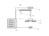
- FIG. 1 shows an example of the configuration of a micro-object manipulation device 200 in this embodiment.
- the micro-object manipulation device 200 can manipulate a micro-object 35 via a flow path member 100.
- the micro-object manipulation device 200 may include all or at least a portion of the flow path member 100, a support section 210, an illumination section 220, a mounting section 230, an imaging section 240, and a control section 250.
- the flow path member 100 is a member equipped with a flow path.
- the flow path member 100 manipulates microscopic objects present in a liquid.
- the flow path member 100 may have an inner peripheral portion and an outer peripheral portion. This will be described in more detail later.
- the support part 210 supports the flow path member 100.
- the support part 210 may support the outer periphery of the flow path member 100.
- the support part 210 supports the flow path member 100.
- the support part 210 supports the flow path member 100 via a joint.
- the support section 210 may be connected to an actuator for the flow path member (not shown). For example, by connecting the support section 210 to the actuator for the flow path member, the flow path member 100 can move in any of the vertical, horizontal, and up-down directions.
- the movement of the actuator for the flow path member may be controlled by the control section 250 (for example, a flow path operation section 255 in the control section 250, which will be described later), or may be controlled by the observer's hand.
- the support section 210 may be formed of a material that transmits light. By forming the support section 210 from a material that transmits light, it is possible to prevent the support section 210 from obstructing illumination when the illumination section 220 illuminates the micro object 35 and/or the flow path member 100.
- the support section 210 may be made of a transparent plastic such as polycarbonate resin or acrylate resin, or glass, but is not limited to these.
- the illumination unit 220 irradiates light onto the flow path member 100 and/or the micro object 35.
- the illumination unit 220 may be disposed above the support unit 210.
- the illumination unit 220 may irradiate light onto the micro object 35 at least partially through the flow path member 100.
- the illumination unit 220 irradiates light onto the micro object 35 via the flow path of the flow path member 100.
- the illumination unit 220 has a ring illumination.
- the illumination unit 220 may irradiate coherent light, and details will be described later.
- the mounting unit 230 mounts the micro-object 35 and/or the container 25 that contains the micro-object 35.
- the mounting unit 230 can move in any of the vertical, horizontal, and up-down directions.
- the mounting unit 230 may mount multiple containers and/or tubes, but is not limited to this.
- the operation of the mounting unit 230 may be controlled by an information processing device such as a computer connected to the mounting unit 230 (e.g., the control unit 250), or may be controlled by the observer's hand.
- the imaging unit 240 captures an image of the micro-object 35 and generates an image. For example, the imaging unit 240 generates a transmission image of the micro-object 35 and generates an image. As an example, the imaging unit 240 captures an image of an operation performed by a fluid on the micro-object 35 close to the tip of the inner periphery, which will be described later.
- the imaging unit 240 may be a camera (such as a cooled camera) that captures a transmission image.
- the imaging unit 240 may be disposed on the surface opposite the flow path member 100 with respect to the mounting unit 230.
- the imaging unit 240 is disposed lower than the mounting unit 230.
- the flow path member 100 can clearly image the manner in which the micro-object 35 is manipulated by the micro-object 35.
- the imaging unit 240 may image the micro-object 35 by enlarging it to any magnification.
- the imaging unit 240 is connected to a microscope.
- the imaging unit 240 uses an objective lens disposed in the optical path of the microscope to magnify and image the manipulation of the micro-object 35 by the air bubble.
- the microscope to be connected may be an inverted microscope device or an upright microscope device.
- the imaging unit 240 may be disposed on the same side as the flow path member 100 with respect to the placement unit 230.
- the imaging unit 240 is disposed directly above or beside the flow path member 100.
- the image data generated by the imaging unit 240 may be stored on an internal hard disk of an information processing device (e.g., the control unit 250) connected to the imaging unit 240, or on an information transmission medium such as a CD, or may be output from a printer or display further connected to the information processing device.
- an information processing device e.g., the control unit 250
- an information transmission medium such as a CD
- the control unit 250 performs overall control of the operation of the micro object manipulation device 200.
- the control unit 250 controls all or at least a part of the operation of the flow path member 100, the illuminance of the illumination unit 220, the operation of the mounting unit 230, the sensitivity of the image sensor of the imaging unit 240, and the brightness of the image captured by the imaging unit 240.
- the control unit 250 may be connected to all or a part of the support unit 210, the illumination unit 220, the mounting unit 230, and the imaging unit 240.
- the control unit 250 may be realized by an information processing device (computer) and/or software.
- the control unit 250 may include all or at least a part of the flow path manipulation unit 255, the illuminance adjustment unit 260, the sensitivity adjustment unit 270, and the brightness adjustment unit 280.
- the flow path operation unit 255 controls the operation of the flow path member actuator to operate the flow path member 100.
- the flow path operation unit 255 may be located inside the control unit 250.
- the flow path operation unit 255 may automatically control the operation of the flow path member actuator, or may control the operation by receiving input from an observer.
- the illuminance adjustment unit 260 adjusts the illuminance of the lighting unit 220.
- the illuminance adjustment unit 260 adjusts the illuminance of the lighting unit 220 so as to properly illuminate the fine object 35.
- the illuminance adjustment unit 260 may be located inside the control unit 250. If the lighting unit 220 includes multiple lights and/or regions, the illuminance adjustment unit 260 may adjust the illuminance for each light and/or region.
- the illuminance adjustment unit 260 may adjust the illuminance automatically, or the illuminance may be adjusted manually by the observer.
- the sensitivity adjustment unit 270 adjusts the sensitivity of the imaging element of the imaging unit 240.
- the sensitivity adjustment unit 270 may adjust the light receiving sensitivity of the imaging element, as will be described in detail below.
- the sensitivity adjustment unit 270 may be located inside the control unit 250.
- the sensitivity adjustment unit 270 may adjust the sensitivity automatically, or the sensitivity may be adjusted manually by the observer.
- the imaging element may be a CMOS image sensor (Complementary Metal Oxide Semiconductor) or a CCD image sensor (Charge Coupled Device).
- the brightness adjustment section 280 adjusts the brightness value of the image captured by the imaging section 240.
- the brightness adjustment section 280 may amplify to increase the brightness only in a specific area in the image, or may attenuate to decrease the brightness.
- the brightness adjustment section 280 may be inside the control section 250.
- the brightness adjustment section 280 may adjust the brightness automatically, or the brightness may be adjusted manually by the observer.
- the brightness adjustment section 280 may adjust the lightness or luminosity instead of/in addition to the brightness.
- the sensitivity adjustment section 270 and the brightness adjustment section 280 may be configured together as an adjustment section.
- the adjustment section may adjust the sensitivity and/or image brightness of the imaging element located directly below the flow path member 100 among the imaging elements of the imaging section 240, based on the sensitivity and/or image brightness of the imaging elements located around and directly below the flow path member 100.
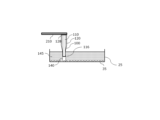
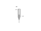
- FIG. 2 shows an example of a flow path member 100 in this embodiment.
- the flow path member 100 is capable of manipulating a micro object 35 present in a liquid by passing a fluid through the flow path.
- the flow path is passed by a fluid to be sucked (intake) or discharged (supply).
- the flow path is provided so as to pass through the longitudinal direction of the flow path member 100.
- the fluid may be a gas and/or a liquid.
- the gas may be air and may contain moisture.
- the gas may be sterile.
- gas that has passed through the flow path member 100 is discharged into the liquid to form bubbles, which can be used to manipulate micro-objects 35 present in the liquid.
- the flow path may pass micro-objects 35 along with the fluid.
- the microscopic object 35 may be a phase object.
- a phase object is an object that imparts a phase change to light when the light is incident on the phase object.
- the phase object may be a transparent object.
- the phase object is a living organism, a droplet structure (micelle, emulsion, etc.), or a microscopic suspended matter (such as debris).
- the living organism may be an organic life form.
- the living organism is a cell.
- the cell is an animal cell or a plant cell.
- the cell is a living cell or a dead cell.
- the organism may be a microorganism other than a cell.
- the microorganism may be a microorganism, a fungus, an algae, a virus, a living tissue, or a spheroid.
- the microorganism may include an organelle within a cell.
- the flow path member 100 may have an inner peripheral portion 110 and an outer peripheral portion 120.
- the inner periphery 110 has a cavity that serves as a fluid flow path and is in contact with the fluid.
- the flow path may be an elongated tubular or cylindrical shape that connects the intake or supply fluid to the inside.
- the inner periphery 110 is straw-shaped or capillary-shaped.
- the longitudinal length of the inner circumferential portion 110 may be 1 mm or more and 50 mm or less.
- the longitudinal length of the inner circumferential portion 110 may be 5 mm or more and 30 mm or less.
- the longitudinal length of the inner circumferential portion 110 may be 10 mm or more and 20 mm or less.
- the inner diameter of the flow path may be 1 ⁇ m or more and 10,000 ⁇ m or less.
- the inner diameter of the flow path may be 10 ⁇ m or more and 1,000 ⁇ m or less.
- the inner diameter of the flow path may be 20 ⁇ m or more and 500 ⁇ m or less.
- the inner circumference 110 may include an inner region 112 and a tip region 114.
- the inner region 112 is a region surrounded by the outer circumference 120.
- the tip region 114 is a region not surrounded by the outer circumference 120 and has a certain length.
- the tip region 114 includes a tip portion 116 that is in close proximity to the micro object 35.
- the tip portion 116 may be disposed in a liquid in which the micro object 35 is immersed.
- the tip portion 116 may form bubbles by introducing gas into the tip portion 116 through the flow path. The method of manipulating the micro object 35 by the tip portion 116 forming bubbles will be described in detail later.
- “closeness” may mean a distance at which the micro object 35 can be physically affected.
- “closeness” is a distance at which the micro object 35 and the tip portion 116 can come into contact with each other through bubbles formed at the tip portion 116.
- the tip surface of the tip portion 116 may be perpendicular to the longitudinal direction of the inner circumference portion 110.
- the tip surface may be a surface that is inclined from a plane perpendicular to the longitudinal direction. The angle between the plane perpendicular to the longitudinal direction and the inclined surface may be 20 degrees or less.
- the inner peripheral portion 110 may be a glass tube.
- the glass tube is formed by a known glass forming technique such as the hand drawing method, the Danner method, or the Bellow method.
- the inner peripheral portion 110 may be a plastic tube, but it is desirable that the plastic tube has a higher strength than the outer peripheral portion 120.
- the outer peripheral portion 120 holds the inner peripheral portion 110 by surrounding all or part of the inner peripheral portion 110 from the outside, thereby protecting the inner peripheral portion 110.
- the outer peripheral portion 120 is the area indicated by diagonal hatching.
- the outer peripheral portion 120 is supported by the support portion 210 at the end portion 128 opposite the tip portion 116. This supports the flow path member 100.
- the longitudinal length of the outer peripheral portion 120 may be 2 mm or more and 100 mm or less.
- the longitudinal length of the outer peripheral portion 120 may be 10 mm or more and 60 mm or less.
- the longitudinal length of the outer peripheral portion 120 may be 20 mm or more and 40 mm or less.
- the outer circumferential portion 120 can adequately hold and protect the inner circumferential portion 110. If the outer circumferential portion 120 is too short, it is difficult to hold and protect the inner circumferential portion 110. If the outer circumferential portion 120 is too long, it is difficult to guide the tip portion 116 to the intended position.
- the outer periphery 120 may surround the inner periphery 110 with the inner region 112.
- the outer periphery 120 surrounds the inner periphery 110 with an enclosing portion 124 on the tip region 114 side of the inner region 112.
- the outer periphery 120 does not have to surround the inner periphery 110 on the side opposite the tip region 114 side of the inner region 112.
- the inner periphery 110 may have a protruding portion 118 that protrudes from the outer periphery 120 toward the opposite side.
- the protruding portion 118 is a portion of the inner periphery 110 that is surrounded by the outer periphery 120 and a void portion 122 described below.
- the outer peripheral portion 120 may be in contact with a part or all of the inner peripheral portion 110 and surround the inner peripheral portion 110.
- the outer peripheral portion 120 has a portion that surrounds the inner peripheral portion 110 without contacting any surface other than the contact surface with the inner peripheral portion 110.
- a void portion 122 that is a gap exists between the inner peripheral portion 110 and the outer peripheral portion 120.
- the outer peripheral portion 120 is a hollow member.
- the outer peripheral portion 120 may have the shape of a cylinder or polygonal prism with a gap in the center portion corresponding to the inner peripheral portion 110 and the gap portion 122.
- the outer peripheral portion 120 may have at least a part of a cylinder that is a cone or a truncated cone, and at least a part of a polygonal prism that is a polygonal pyramid or a truncated polygonal pyramid.
- the central axis of the cone, truncated cone, polygonal pyramid, and truncated polygonal pyramid may coincide with the central axis of the inner peripheral portion 110 in the longitudinal direction.
- the outer circumferential portion 120 has a tapered shape on the tip region 114 side of the inner region 112 (e.g., all or part of the surrounding portion 124) in which the cross-sectional area in a plane perpendicular to the longitudinal direction of the inner circumferential portion 110 decreases toward the tip portion 116.
- the outer circumferential portion 120 have a tapered shape on the tip region 114 side of the inner region 112 when the illumination unit 220 illuminates the micro-object 35, the micro-object 35 located around and directly below the flow path member 100 (vertically below the flow path member 100 in the longitudinal direction) can be brightly illuminated. Details will be described later.
- the end face of the outer peripheral portion 120 opposite the tip portion 116 coincides with the opposite end face of the inner peripheral portion 110 (the upper end face in FIG. 2) (end 128 in FIG. 2), but the positions of the end faces of the outer peripheral portion 120 and the inner peripheral portion 110 are not limited to this.
- the upper end face of the inner peripheral portion 110 may be located lower than the upper end face of the outer peripheral portion 120.
- the outer peripheral portion 120 is in the form of a container that can hold a fluid in the void portion 122.
- the tip region 114 of the flow path member 100 is folded or cut and sealed as necessary, so that the outer peripheral portion 120 can be used as it is as a container for storing the fine object 35 or liquid.
- the outer peripheral portion 120 may be formed from a material that is easier to mold than the inner peripheral portion 110.
- the outer peripheral portion 120 may be formed from a resin that is easier to mold than glass.
- the outer peripheral portion 120 is formed by insert molding or injection molding. In the case of insert molding, the inner peripheral portion 110 (e.g., a glass tube) is first set in a mold. Next, the material that will form the outer peripheral portion 120 is filled into the mold.
- the flow path member 100 may be manufactured by penetrating the inner peripheral portion 110 to the tip of the outer peripheral portion 120.
- the flow path member 100 can be manufactured after the inner peripheral portion 110 and the outer peripheral portion 120 are prepared separately, so that the flow path member 100 of the component desired by the observer can be manufactured.
- the material forming the outer circumferential portion 120 may have a lower melting temperature than the material forming the inner circumferential portion 110.
- the material forming the outer circumferential portion 120 has a lower melting point than the material forming the inner circumferential portion 110. This allows the material forming the outer circumferential portion 120 to melt at a lower temperature than the material forming the inner circumferential portion 110, making it easier to mold into any shape.
- the material forming the outer circumferential portion 120 has a lower glass transition point than the material forming the inner circumferential portion 110.
- the material forming the outer circumferential portion 120 becomes soft at a lower temperature than the material forming the inner circumferential portion 110, making it easier to mold into any shape.
- Measurement of the glass transition point may be performed using a differential scanning calorimeter, but is not limited to this.
- the material forming the outer circumferential portion 120 may be more easily deformed than the material forming the inner circumferential portion 110.
- the material forming the outer circumferential portion 120 has a lower Young's modulus at room temperature (e.g., about 20°C, about 25°C, or about 30°C, etc.) than the material forming the inner circumferential portion 110.
- Young's modulus is a value that indicates the relationship between strain and stress, and the smaller the value, the easier the material is to deform. This makes the material forming the outer circumferential portion 120 more easily deformable than the material forming the inner circumferential portion 110, making it easier to mold into any shape.
- the measurement of Young's modulus may be performed according to the ASTM D638 standard, but is not limited to this.
- the material forming the inner peripheral portion 110 may have a higher light transmittance value at wavelengths of 400 nm, 450 nm, 500 nm, 550 nm, 600 nm, 650 nm, or 700 nm than the material forming the outer peripheral portion 120.
- the material forming the inner peripheral portion 110 may have a higher light transmittance value at all wavelengths in the visible light range from 400 nm to 700 nm than the material forming the outer peripheral portion 120.
- the material forming the inner peripheral portion 110 may have a lower light scattering property at wavelengths of 400 nm, 450 nm, 500 nm, 550 nm, 600 nm, 650 nm, or 700 nm than the material forming the outer peripheral portion 120.
- the light transmittance and/or scattering property may be measured using a spectrophotometer, but is not limited to this.
- the material forming the inner circumference 110 has a higher light transmittance value than the material forming the outer circumference 120, so the material forming the inner circumference 110 transmits light more easily, which is advantageous for the illumination unit 220 to irradiate the flow path member 100 with light, and for the light to illuminate the micro-object 35 through the inner circumference 110.
- the material forming the inner peripheral portion 110 may have a smaller refractive index at room temperature than the material forming the outer peripheral portion 120.
- the difference in refractive index between the material forming the inner peripheral portion 110 and the material forming the outer peripheral portion 120 may be 0.2 or more. This difference in refractive index may be 0.3 or more. This difference in refractive index may be 0.5 or more.
- the refractive index of light may be measured using the critical angle method, but is not limited to this.
- the refractive index of the material forming the outer circumferential portion 120 is at least 0.2 greater than the refractive index of the material forming the inner circumferential portion 110, so that even if light attempts to enter the inner circumferential portion 110 from the outer circumferential portion 120, the light can be totally reflected at the boundary between the outer circumferential portion 120 and the inner circumferential portion 110. This makes it possible to prevent light from entering the inner circumferential portion 110 from the outer circumferential portion 120.
- the material forming the inner circumference 110 can be any material that can be precisely machined and has high strength, without any restrictions.
- the material forming the inner circumference 110 is glass or metal.
- glass include borosilicate glass and soda-lime glass.
- metals include stainless steel, titanium alloys, and aluminum alloys.
- the melting point of borosilicate glass is approximately 820°C, and the melting point of aluminum is approximately 660°C.
- the material forming the outer periphery 120 can be any material that can be molded without any restrictions.
- the material forming the outer periphery 120 is a resin.
- the resin may be polypropylene resin, polyethylene resin, polystyrene resin, PET resin, polyvinyl chloride resin, polycarbonate resin, etc., but is not limited to these.
- the melting point of polycarbonate resin is approximately 150°C.
- the flow path member 100 has an outer periphery 120 which is weak but easy to mold, and an inner periphery 110 which is difficult to mold but strong, making it possible to utilize the advantages of both the inner periphery 110 and the outer periphery 120.
- the flow path member 100 obtained in this way allows the micro-object 35 to be easily manipulated, and can be mass-produced at low cost.
- Figures 3A, 3B, and 3C show an example of a method for recovering a micro-object 35 in this embodiment.
- Figures 3A, 3B, and 3C show adherent cells as an example of the micro-object 35.
- the adherent cells are cultured on a solid phase on the inner bottom surface of a transparent container 25.
- the adherent cells may be immersed in a liquid 145 in the container 25.
- the liquid 145 may be a complete medium, a basal medium, or a buffer solution. If the micro-object 35 is not a living organism or is a dead cell, the liquid is not limited to these, and may be water, an organic solvent, or the like.
- a pump (not shown) connected to the end 128 of the inner periphery 110 opposite the tip 116 supplies gas to the flow path of the inner periphery 110.
- This forms a gas bubble 140 at the tip 116.
- the formed gas bubble 140 comes into contact with the adherent cells.
- the pump adjusts the supply and intake of gas to maintain the gas bubble 140 formed at the tip 116.
- the adherent cells may be manipulated using the gas bubble 140 formed and maintained at the tip 116. By maintaining the gas bubble 140, the adherent cells can be easily manipulated.
- the support part 210 connected to the end part 128 of the inner circumference part 110 opposite the tip part 116 moves the flow path member 100 along the surface of the solid phase while keeping the air bubbles 140 in contact with the adherent cells.
- the support part 210 moves the flow path member 100 from left to right, but the direction in which the support part 210 moves the flow path member 100 is not limited as long as it is a direction parallel to the surface of the solid phase.
- the air bubbles 140 move and the adherent cells adhere to the air bubbles 140 and/or an external force is applied, so that the adherent cells can be detached from the solid phase. At this time, the detached adherent cells adhere to the air-liquid interface of the air bubbles 140.
- the pressure and/or volume of the gas being supplied or sucked in can be controlled. This allows the size of the air bubbles 140 to be changed, so that adherent cells within a desired range can be detached.
- the placement section 230 may be moved to detach the adherent cells from the solid phase.
- the pump sucks in the gas in the flow path of the inner periphery 110, thereby recovering the adherent cells attached to the gas bubbles 140 inside the inner periphery 110.
- the gas bubbles 140 formed at the tip 116 can be used to selectively detach and recover the adherent cells from the solid phase.
- the recovered cells may be released into another container or a slide glass to move the adherent cells. This allows the adherent cells to be subcultured, observed, or stained.
- the flow path member 100 can easily manipulate the micro-object 35 in the liquid.
- adherent cells have been exemplified as the micro-object 35
- suspended cells may also be used.
- the tip 116 may be brought close to the suspended cell by aspirating the fluid (gas or liquid) contained in the flow path of the inner circumference 110 without forming an air bubble 140 at the tip 116, and the micro-object 35 may be taken into the flow path of the inner circumference 110. This operation makes it easy to observe and/or recover the suspended cell.
- the support section 210 has been shown to move the flow path member 100 along the surface of the solid phase while keeping the air bubbles 140 in contact with the adherent cells, but the manipulation of adherent cells is not limited to this.
- the volume of the air bubbles 140 may be increased while keeping the support section 210 fixed, thereby moving the air-liquid interface of the air bubbles 140, causing the adherent cells to adhere to the air bubbles 140 and/or detach from the solid phase.
- FIGS. 4A, 4B, and 4C show an example of a flow path member 100 in this embodiment.
- the flow path member 100 in FIG. 4A, 4B, and 4C uses borosilicate glass as the material for forming the inner periphery 110, and uses polycarbonate resin as the material for forming the outer periphery 120.
- the flow path member 100 has a gap 122 between the inner periphery 110 and the outer periphery 120.
- FIGS. 4A and 4B show bright field images taken by positioning the illumination unit 220 directly above the two flow path members 100 shown in FIG. 4A and FIG. 4B (vertically above the flow path members 100 in the longitudinal direction) and illuminating the micro object 35 located directly below the tip 116 through the flow path members 100.
- the micro object 35 can be observed more clearly in an image of the micro object 35 located directly below the flow path member 100 in FIG. 4B than in an image of the micro object 35 located directly below the flow path member 100 shown in FIG. 4A.
- the flow paths may be filled with liquid (e.g., buffer solution, culture medium, etc.) beforehand before imaging.
- a clear bright-field observation image can be obtained by irradiating the micro-object 35 with coherent light (here, the coherent light is an illumination light with an illumination NA of almost zero and a width of the coherence function sufficiently wide compared to the wavelength) from the illumination unit 220.
- the illumination unit 220 irradiates the flow path member 100, the light that passes through the inner circumference 110, which is glass, does not have a phase disturbance, and the coherent light is irradiated to the micro-object 35 directly below the inner circumference 110, and an observation image with high contrast is obtained.
- the light that passes through the outer circumference 120, which is resin is scattered and becomes incoherent light with a disturbed phase.
- the phase of the light illuminating the micro-object 35 is disturbed, the effective illumination NA becomes large (the width of the coherence function becomes small), and the contrast decreases during bright-field observation, causing the image of the micro-object 35 to become unclear.
- the contact area may be 0.5 mm2 to 4 mm2 inclusive.
- the contact area may be 0.8 mm2 to 3 mm2 inclusive.
- the contact area may be 1 mm2 to 2 mm2 inclusive.
- the contact area When the contact area is within the above range, the micro object 35 can be clearly observed.
- the contact area between the inner peripheral portion 110 and the outer peripheral portion 120 exceeds 4 mm2, the amount of light that passes through the inside of the outer peripheral portion 120 entering the inner peripheral portion 110 increases, making it difficult to clearly observe the micro object 35.
- the contact area between the inner peripheral portion 110 and the outer peripheral portion 120 is less than 0.5 mm2 , it becomes difficult to insert mold the outer peripheral portion 120 to manufacture the flow path member 100.
- FIGS. 5A, 5B, 5C, and 5D are diagrams illustrating the porosity and filling rate of the outer peripheral portion 120 in this embodiment.
- the filling rate of the outer peripheral portion 120 may be 30% or more and 80% or less.
- the filling rate may be 40% or more and 70% or less.
- the filling rate may be 50% or more and 60% or less.
- the porosity is defined as an index showing the volume of the void portion 122.
- the porosity is the ratio of the volume V2 of the void portion 122 to the apparent volume V1 of the outer peripheral portion 120 including the void portion 122.
- the apparent volume V1 of the outer peripheral portion 120 including the void portion 122 means the volume of the spatial region surrounded by the material forming the outer peripheral portion 120 (the volume of the closed space shown in FIG. 5B).
- V1 also includes the volume of the void portion 122.
- the volume V2 of the void portion means the volume of the region surrounded by the material forming the outer peripheral portion 120 minus the volume of the spatial region occupied by the material forming the outer peripheral portion 120 (i.e., the actual volume of the outer peripheral portion 120) (the volume of the white portion shown in FIG. 5C).
- the filling ratio is the ratio of the actual volume V3 of the outer peripheral portion 120 that does not include the void portion 122 to the apparent volume V1 of the outer peripheral portion 120 that includes the void portion 122 (the volume of the shaded portion shown in FIG. 5D).
- the filling rate When the filling rate is within the range of 30% to 80%, the micro-object 35 can be clearly observed. If the filling rate exceeds 80%, a large amount of light that passes through the inside of the outer peripheral portion 120 enters the inner peripheral portion 110, making it difficult to clearly observe the micro-object 35. If the filling rate is less than 30%, the strength of the outer peripheral portion 120 cannot be maintained, making it difficult to hold the inner peripheral portion 110 and for the support portion 210 to support the outer peripheral portion 120.
- the longitudinal length L of the inner periphery 110 of the flow path member 100 shown in Figures 4A and 4C is 2.0 cm, and the inner periphery 110 reaches the end 128 opposite the tip 116 of the outer periphery 120.
- the longitudinal length L of the inner periphery 110 of the flow path member 100 shown in Figure 4B is 1.4 cm, which is shorter than the longitudinal length of the inner periphery 110 of the flow path member 100 shown in Figures 4A and 4C and does not reach the end 128.
- the flow path members 100 in Figures 4A, 4B, and 4C have the same apparent volume V1 of the outer periphery 120 including the void portion 122, but the volume V2 of the void portion 122 is different.
- the contact area ratio is defined by the following formula 4.
- Contact area ratio (%) 100 ⁇ (contact area between inner circumferential portion 110 and outer circumferential portion 120/cross-sectional area in a plane perpendicular to the longitudinal direction of inner circumferential portion 110).
- the contact area ratio is the ratio of the area (contact area) of the contact portion between the inner peripheral portion 110 which is a glass tube and the outer peripheral portion 120 which is a resin to the cross-sectional area of the inner peripheral portion 110 which is a glass tube.
- the contact area, filling rate, and contact area ratio of the flow path member 100 used in Figures 4A, 4B, and 4C are shown in Table 1.
- the illumination units 220 are positioned directly above each of the three flow path members 100, and bright field images of the micro object 35 located directly below the tip 116 through the flow path members 100 are shown in Figures 4A, 4B, and 4C, respectively.
- the outline of the micro object 35 is not visible. However, in the image of the micro object 35 located directly below the flow path member 100 in FIG. 4B, the outline is visible. Furthermore, in the image of the micro object 35 located directly below the flow path member 100 in FIG. 4C, the micro object 35 is observed more clearly. The reason for this is that in the flow path member 100 in FIG. 4B and FIG. 4C, the volume of the void portion 122 is larger (i.e., the value of the filling rate is smaller) than in the flow path member 100 in FIG. 4A, so the amount of light that directly enters the inner peripheral portion 110 from the outer peripheral portion 120 is reduced. This is thought to be due to the reduction in the phase disturbance of the light with which the illumination unit 220 illuminates the micro object 35.
- the contact area ratio of the flow path member 100 may be 50,000% (500x) or less, or 30,000% (300x) or less. When the contact area ratio is within the range of 50,000% (500x) or less, or 30,000% (300x) or less, the micro-object 35 can be clearly observed.
- a portion of the contact area between the inner periphery 110 and the outer periphery 120 may have a light-shielding area in which a light-shielding member is disposed.
- the area excluding the light-shielding area from the contact area may be regarded as the contact area between the inner periphery 110 and the outer periphery 120.
- a light-shielding member may be disposed on at least one of the inner circumferential portion 110 and the outer circumferential portion 120.
- the light-shielding member is disposed on at least a portion of the inner circumferential portion 110 or the outer circumferential portion 120 where the inner circumferential portion 110 and the outer circumferential portion 120 contact each other. This prevents light that has passed through the inside of the outer circumferential portion 120 from entering the inner circumferential portion 110.
- the light-shielding member is disposed on the incident surface of the outer circumferential portion 120 where light is incident.
- the light-shielding member is disposed on the incident surface of the light that is incident on the outer circumferential portion 120, among both ends of the outer circumferential portion 120 in the longitudinal direction. This reduces the light that enters the outer circumferential portion 120 and prevents light that has passed through the inside of the outer circumferential portion 120 from entering the inner circumferential portion 110.
- At least one of the longitudinal ends of the outer circumferential portion 120 may contain a light absorber and/or a light scatterer as a light blocking member.
- a light blocking sheet may be provided as a light blocking member at least in a portion between the inner circumferential portion 110 and the outer circumferential portion 120.
- the light absorber absorbs light passing through the inside of the outer peripheral portion 120 and prevents light from entering from the outer peripheral portion 120 into the inner peripheral portion 110.
- carbon black particles or metal oxide particles such as iron tetroxide particles can be used as the light absorber.
- the color of the light absorber is not limited to black, and any dark color such as gray, dark blue, dark green, or brown may be used.
- the light scatterer scatters the light passing through the inside of the outer periphery 120 in multiple directions, preventing the light from entering the inner periphery 110 from the outer periphery 120. Specifically, the light that passes through the resin inside the outer periphery 120 is scattered in multiple directions by the light scatterer, reducing the amount of light that enters the inner periphery 110 and preventing the light from entering the inner periphery 110 from the outer periphery 120. There are no limitations on the type of light scatterer as long as it can scatter light.
- the light scatterer may be inorganic or organic particles that scatter light well in the visible light range.
- the light scatterer may be white paint, titanium dioxide particles, zinc oxide particles, silicon dioxide particles, calcium carbonate particles, acrylic particles, etc., but is not limited to these.
- the flow path member 100 shown in FIG. 6A uses the same material as the flow path member shown in FIG. 4A.
- the flow path member 100 shown in FIG. 6B uses the same material as the flow path member shown in FIG. 4A, but differs in that the outer periphery 120 is made of polycarbonate resin mixed with 0.018 weight percent black paint (containing carbon black particles), which is a light-shielding material.
- the flow path member 100 shown in FIG. 6B contains black paint in the outer periphery 120, so the outer periphery 120 is darkened black.
- the illumination unit 220 is positioned directly above the two flow path members 100 shown in Fig. 6A and Fig. 6B (vertically above the longitudinal direction of the flow path members 100), and bright field images of the micro object 35 located directly below the tip 116 through the flow path members 100 are shown in Fig. 6A and Fig. 6B, respectively.
- the micro object 35 can be observed more clearly in the image of the micro object 35 located directly below the flow path member 100 in Fig. 6B than in the image of the micro object 35 located directly below the flow path member 100 shown in Fig. 6A.
- the light-shielding sheet may be in the form of a sheet or film coated with aluminum or metal oxide, or may be coated with black paint containing carbon black particles, but is not limited to these as long as it has the light-shielding function.
- the outer periphery 120 can be light-shielded by coating at least a portion of the resin of the outer periphery 120 on the side facing the inner periphery 110 with black paint containing carbon black particles.
- the inner periphery 110 may be shaded.
- the inner periphery 110 can be shaded by applying a black paint containing carbon black particles to at least a portion of the side of the inner periphery 110 that faces the outer periphery 120.
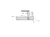
- FIG. 6C shows another example of a flow path member 100 in this embodiment.
- the longitudinal length L of the inner circumferential portion 110 may be longer than, equal to, or significantly shorter than the longitudinal length (vertical direction in the figure) of the outer circumferential portion 120.
- the length of the inner circumferential portion 110 may be, but is not limited to, twice, the same, 1 ⁇ 2 or less, 1 ⁇ 3 or less, 1 ⁇ 4 or less, or 1 ⁇ 5 or less of the longitudinal length of the outer circumferential portion 120.
- the longitudinal length L of the inner circumferential portion 110 of the flow path member 100 may be 1 mm or more and 50 mm or less.
- the longitudinal length L of the inner circumferential portion 110 may be 5 mm or more and 30 mm or less.
- the longitudinal length L of the inner circumferential portion 110 may be 10 mm or more and 20 mm or less.
- the longitudinal length L of the inner circumference 110 When the longitudinal length L of the inner circumference 110 is within the above range, the micro-object 35 can be clearly observed. If the longitudinal length L of the inner circumference 110 exceeds 50 mm, the light passing through the inside of the flow path is reflected inside the flow path, making it difficult to clearly observe the micro-object 35. If the longitudinal length L of the inner circumference 110 is less than 1 mm, it becomes difficult to insert mold the outer circumference 120 to manufacture the flow path member 100.
- FIG. 6C shows an example of a flow path member 100.
- the flow path member 100 in FIG. 6C is made of the same material as the flow path member 100 in FIG. 6A, but the longitudinal length L of the inner periphery 110 is different.
- the longitudinal length L of the inner periphery 110 of the flow path member 100 in FIG. 6A is 20 mm, and the inner periphery 110 reaches the end 128 opposite the tip 116 of the outer periphery 120.
- the longitudinal length L of the inner periphery 110 of the flow path member 100 in FIG. 6C is 0.7 mm, which is shorter than the longitudinal length of the inner periphery 110 of the flow path member 100 in FIG. 6A and does not reach the end 128.
- the illumination unit 220 is positioned directly above the flow path member 100 in FIG. 6C, and a phase contrast image is shown of the micro object 35 located directly below the tip 116 through the flow path member 100.
- the micro object 35 can be observed more clearly in the image of the micro object 35 located directly below the flow path member 100 in FIG. 6C than in the image of the micro object 35 located directly below the flow path member 100 in FIG. 6A.
- the longitudinal length L of the inner circumferential portion 110 is longer than 50 mm, it is believed that the light will be excessively reflected within the flow path, making it difficult to clearly observe the micro-object 35. Therefore, by shortening the longitudinal length L of the inner circumferential portion 110 to 50 mm or less, the light that has passed through the inside of the outer circumferential portion 120 is prevented from being reflected within the inner circumferential portion 110, and the micro-object 35 can be clearly observed.
- the longitudinal length of the inner circumferential portion 110 may be 1/2 or less of the longitudinal length of the outer circumferential portion 120.
- the volume occupied by the inner periphery 110 is expressed as the product of the cross-sectional area of the flow path constituting the inner periphery 110 (the area of the cross section in a plane perpendicular to the longitudinal direction of the inner periphery 110) and the length L of the inner periphery 110.
- the longitudinal length L of the inner periphery 110 is shortened, the volume occupied by the inner periphery 110 is reduced, and therefore the amount of liquid sucked into the flow path of the inner periphery 110 when manipulating the micro object 35 can be reduced.
- FIG. 7A is a diagram explaining the taper angle of the outer circumferential portion 120 in this embodiment.
- the taper angle ⁇ means the angle between the longitudinal direction of the inner circumferential portion 110 and the side of the tapered portion whose cross-sectional area in a plane perpendicular to the longitudinal direction of the inner circumferential portion 110 decreases as the outer circumferential portion 120 approaches the tip portion 116.
- the taper angle ⁇ may be 4 degrees or more and 80 degrees or less.
- the taper angle ⁇ may be 6 degrees or more and 50 degrees or less.
- the taper angle ⁇ may be 8 degrees or more and 20 degrees or less.
- the taper angle ⁇ may be 8.5 degrees or more and 10 degrees or less.
- the taper angle is 4 degrees or less, the amount of light that passes through the inside of the outer peripheral portion 120 and enters the inner peripheral portion 110 increases, making it difficult to clearly observe the micro-object 35. Furthermore, if the diameter of the flow path member 100 is large, the length of the flow path member 100 in the longitudinal direction becomes very large, making it difficult to operate the flow path member 100. If the taper angle exceeds 80 degrees, the illumination unit 220 (e.g., the auxiliary illumination described later) is prevented from illuminating the area immediately below the inner peripheral portion 110, making it difficult to clearly observe the micro-object 35 present in the area immediately below the inner peripheral portion 110. Furthermore, since the taper angle is close to 90 degrees, the incoherent light generated by passing through the outer peripheral portion 120 directly illuminates the micro-object 35 present in the area immediately below the inner peripheral portion 110, making it difficult to clearly observe the micro-object 35.
- the illumination unit 220 e.g., the auxiliary illumination described later
- the cross section of the tip 116 of the flow path member 100 may be smooth without scratches or irregularities.
- the surface roughness of the cross section of the tip 116 perpendicular to the longitudinal direction of the inner periphery 110 may be an arithmetic mean roughness (Ra) of 20 ⁇ m or less and/or a maximum height (Rz) of 30 ⁇ m or less.
- the arithmetic mean roughness may be considered as an index of the average height difference in the cross section.
- the maximum height may be considered as an index of the maximum height difference in the cross section. If the arithmetic mean roughness exceeds 20 ⁇ m or the maximum height exceeds 30 ⁇ m, the cross section of the tip 116 will not be smooth, so that the bubbles 140 will not be formed properly and the micro-object 35 may not be able to be manipulated properly. If the arithmetic mean roughness exceeds 20 ⁇ m or the maximum height exceeds 30 ⁇ m, the effect of light refraction in the cross section of the tip 116 will be large, and the illumination unit 220 may not be able to illuminate the micro-object 35 uniformly.
- the average distance between the unevennesses may be 5 times or more, or 10 times or more, the wavelength. If the distance between the unevennesses is 5 times or less the wavelength, the light will be diffusely reflected, reducing the contrast during bright-field observation of the micro-object 35, causing the image of the micro-object 35 to become unclear.
- the measurement conditions and calculation method for the arithmetic mean roughness and/or maximum height may be in accordance with "ISO 25178 Surface quality (surface roughness measurement)".
- the arithmetic mean roughness may be measured non-contact using a 3D measuring laser microscope, etc.
- FIG. 7B shows another example of a flow path member 100 in this embodiment.
- the flow path member 100 shown in FIG. 7B has a slope on the outer edge 130 at the end 128 of the outer periphery 120, and on the outer periphery bottom 132 on the tip region 114 side of the gap 122 of the outer periphery 120. Light illuminating the flow path member 100 from directly above tends to be incident on the flat portion of the end 128.
- the inclination angle ⁇ which is the angle between the inclined surface and the longitudinal direction of the flow path member 100, may be within the same angle range as the taper angle ⁇ , for example, 4 degrees to 80 degrees, 6 degrees to 50 degrees, 8 degrees to 20 degrees, or 8.5 degrees to 10 degrees
- the inclination angle ⁇ which is the angle between the longitudinal direction of the flow path member 100
- may be a negative angle for example, -80 degrees to -4 degrees, -50 degrees to -6 degrees, -20 degrees to -8 degrees, or -10 degrees to -8.5 degrees).
- FIG. 8 shows an example of the configuration of the illumination unit 220 of the micro-object manipulation device 200 in this embodiment (the control unit 250 is excluded).
- the illumination unit 220 may have at least two types of illumination: a main illumination 221 and a sub-illumination 222.
- Figure 9 shows a perspective view of the micro-object manipulation device 200 of Figure 8 (imaging unit 240 is omitted).
- the main lighting 221 illuminates the flow path member 100 from directly above (C in Figure 9 shows the optical path of the main lighting).
- the main lighting 221 may irradiate the flow path member 100 with light along the longitudinal direction of the inner circumference 110 (not shown).
- the light incident on the inner circumference 110 from the main lighting 221 may be emitted from the tip 116.
- the main lighting 221 may irradiate coherent light.
- the coherent light may be, but is not limited to, light from a halogen lamp, light from a mercury lamp, light from an LED, or laser light.
- the shape of the main illuminator 221 is not particularly limited, but may be disk-shaped, ring-shaped, or rectangular. When the main illuminator 221 irradiates coherent light, the light enters the inner circumference 110, and a bright-field image of the micro-object 35 located directly below the inner circumference 110 can be clearly observed.
- the secondary illumination 222 illuminates the micro-object 35 from an oblique direction of the flow path member 100 (P in FIG. 9 indicates the optical path of the secondary illumination).
- the secondary illumination 222 may be a ring illumination that irradiates a ring-shaped light that circumferentially surrounds the flow path member 100.
- the secondary illumination 222 is an oblique ring illumination.
- Figure 9 shows an example of the secondary illumination 222 being an oblique ring illumination.
- FIG. 10 shows an example of a bright-field image of a micro-object in this embodiment.
- the light intensity can be adjusted automatically by an information processing device such as a computer (e.g., the control unit 250) connected to the illumination unit 220, or can be adjusted manually by the observer.
- a computer e.g., the control unit 250
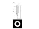
- FIG. 11 shows another example of the configuration of the illumination unit 220 of the micro-object manipulation device 200 in this embodiment (the control unit 250 is excluded).
- the illumination unit 220 has a light source 225.
- the illumination unit 220 may have an aperture 226, a filter 227, and a condenser lens 228 to split the light from the light source 225 into two: light that illuminates the micro-object 35 from directly above (sometimes called central light) and light that illuminates the area directly below, i.e., the area surrounding the central light (sometimes called peripheral light).
- FIG. 12 shows a perspective view of the micro-object manipulation device 200 of FIG. 11 (the imaging unit 240 is omitted).
- the light source 225 may illuminate the micro-object 35 from directly above the flow path member 100, and may illuminate directly below, the surrounding area directly below, and the inside of the inner periphery 110.
- the light source 225 may emit coherent light.
- the diaphragm 226 adjusts the amount of light from the light source 225.
- the light from the light source 225 can be made to be only central light (C in FIG. 12 indicates the optical path of the central light).
- the light from the light source 225 can be made to be both central light and peripheral light (P in FIG. 12 indicates the optical path of the peripheral light).
- the amount of peripheral light can be adjusted by adjusting the opening degree of the diaphragm 226.
- the diaphragm 226 may be automatically adjusted by an information processing device such as a computer connected to the illumination unit 220 (e.g., the control unit 250), or may be adjusted manually by the observer.
- Filter 227 splits the light from light source 225 into central light and peripheral light.
- Filter 227 may have a circular hole in the center and an annular hole in the peripheral portion around the center. When light from light source 225 passes through the center of filter 227, it becomes central light, and when light passes through the peripheral portion of filter 227, it becomes peripheral light.
- the hole in the center of filter 227 may have a diameter of 10 mm or less so that the central light does not illuminate anything other than flow path member 100.
- the focusing lens 228 may focus the central light from the filter 227 and cause the central light to enter the inner circumference 110 (not shown).
- the central light that enters the inner circumference 110 exits the tip 116 and illuminates the micro-object 35 from directly above (C in FIG. 12 shows the optical path of the central light).
- the focusing lens 228 may focus the peripheral light from the filter 227 and illuminate the micro-object 35 from an oblique direction (P in FIG. 12 shows the optical path of the peripheral light).
- the light source 225 irradiates coherent light
- the light that illuminates the micro-object 35 from directly above may contain coherent light
- the light that illuminates the micro-object 35 from an oblique direction may contain incoherent light.
- the brightness of the central light can be adjusted by adjusting the brightness of the light source 225 itself using the illuminance adjustment unit 260, and the brightness of the peripheral light can be adjusted by the aperture 226 to adjust the illuminance of the peripheral light illuminating the fine object 35.
- the illumination unit 220 can further include the aperture 226, filter 227, and condenser lens 228, so that the light source 225 illuminating the fine object 35 can be divided into two lights, central light and peripheral light.
- the cost of the light source 225 emitting coherent light can be reduced.
- the illumination unit 220 can further include the aperture 226, filter 227, and condenser lens 228, so that the amount of coherent light in the central light and the amount of incoherent light in the peripheral light can be adjusted.
- FIG. 13A shows an example of the micro-object manipulation device 200 in this embodiment and an image of the micro-object 35 captured by the micro-object manipulation device 200.
- the x-axis and y-axis indicate orthogonal axes of a two-dimensional coordinate system with the origin being a position directly below the flow path member 100.
- the imaging unit 240 may generate an image in which the micro object 35 directly below the flow path member 100 is imaged darker than the micro object 35 around it. This is thought to be due in part to the fact that part of the light from the illumination unit 220 is blocked by the outer periphery 120 of the flow path member 100, causing the area directly below the flow path member 100 to be in the shadow of the outer periphery 120.
- the sensitivity adjustment unit 270 may be controlled to adjust the sensitivity of the imaging element so that the micro object 35 directly below the flow path member 100 generates an image that is as bright as the micro object 35 surrounding it.
- the sensitivity adjustment unit 270 adjusts the sensitivity of the imaging element located directly below the flow path member 100 among the imaging elements of the imaging unit 240, based on the sensitivity of the imaging elements located directly below the flow path member 100 and in the surrounding area.
- the sensitivity adjustment unit 270 may adjust the sensitivity of the imaging element located directly below the flow path member 100 among the imaging elements of the imaging unit 240, so that it is higher than the sensitivity of the imaging elements located directly below the flow path member 100 and in the surrounding area.
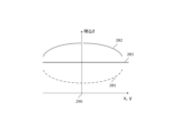
- FIG. 13B is a diagram explaining the above adjustment.
- Point 290 indicates the position directly below flow path member 100
- the horizontal axis (x, y) indicates the distance from point 290
- the vertical axis indicates relative brightness.
- Curve 281 indicates the relative brightness of the image captured by imaging section 240. Curve 281 indicates that the brightness is darkest directly below flow path member 100 (point 290).
- the sensitivity adjustment unit 270 may adjust the sensitivity automatically or manually by the observer so that the sensitivity of the imaging element located directly below the flow path member 100 (point 290) is the highest, and the sensitivity of the imaging elements located around the area directly below the flow path member 100 is gradually increased toward the area directly below.
- Curve 282 shows the relative value of the sensitivity of the imaging element when the sensitivity is adjusted in this way.
- Line 283 shows the brightness of the image obtained by the adjustment. By adjusting in this way, the area directly below the flow path member 100 can be made as bright as the area directly below it.
- the brightness adjustment unit 280 may be controlled to adjust the brightness so that the image of the micro object 35 directly below the flow path member 100 is as bright as the surrounding micro object 35.
- the brightness adjustment unit 280 adjusts the brightness of the image located directly below the flow path member 100 among the images captured by the imaging unit 240, based on the brightness of the images located around the flow path member 100.
- the brightness adjustment unit 280 may adjust the brightness of the image located directly below the flow path member 100 among the images captured by the imaging unit 240, so that it is amplified higher than the brightness of the images located around the flow path member 100.
- the brightness adjustment section 280 may adjust the brightness automatically or manually by the observer so as to amplify the brightness of the image located directly below the flow path member 100 (point 290) to the highest level, and amplify the brightness of the image located around the area directly below the flow path member 100 gradually higher toward the area directly below.
- Curve 282 shows the relative value of the rate at which the brightness is amplified when adjusted in this way.
- Line 283 shows the brightness of the image obtained by the adjustment. By adjusting in this way, the area directly below the flow path member 100 can be made as bright as the area directly below it.
- Such adjustment of the sensitivity adjustment unit 270 and/or brightness adjustment unit 280 may be performed in accordance with the operation of the flow path member 100.
- By adjusting the sensitivity or brightness in accordance with the operation of the flow path member 100 it is possible to observe a bright image directly below the flow path member 100 in real time.
- the image of the micro object 35 directly below the flow path member 100 becomes as bright as the images of the micro objects 35 surrounding it, and images of uniform brightness can be obtained for both the micro object 35 located directly below the flow path member 100 and the micro objects 35 located directly below and in the surrounding area.
- Micro object 100 Flow path member 110 Inner circumference 112 Inside region 114 Tip region 116 Tip 118 Protrusion 120 Outer circumference 122 Gap 124 Surrounding portion 128 End 130 Outer edge 132 Outer bottom 140 Air bubble 145 Liquid 200
- Micro object manipulation device 210 Support 220 Illumination section 221 Main illumination 222 Secondary illumination 225
- Light source 226 Aperture 227 Filter 228 Condenser lens 230 Placement section 240 Imaging section 250 Control section 255 Flow path manipulation section 260 Illuminance adjustment section 270 Sensitivity adjustment section 280 Brightness adjustment section 281 Curve 282 Curve 283 Straight line 290 points
Landscapes
- Health & Medical Sciences (AREA)
- Life Sciences & Earth Sciences (AREA)
- Chemical & Material Sciences (AREA)
- Organic Chemistry (AREA)
- Engineering & Computer Science (AREA)
- Bioinformatics & Cheminformatics (AREA)
- Zoology (AREA)
- Wood Science & Technology (AREA)
- Sustainable Development (AREA)
- Microbiology (AREA)
- Biotechnology (AREA)
- Biomedical Technology (AREA)
- Biochemistry (AREA)
- General Engineering & Computer Science (AREA)
- General Health & Medical Sciences (AREA)
- Genetics & Genomics (AREA)
- Molecular Biology (AREA)
- Analytical Chemistry (AREA)
- Apparatus Associated With Microorganisms And Enzymes (AREA)
Priority Applications (2)
| Application Number | Priority Date | Filing Date | Title |
|---|---|---|---|
| JP2024551859A JPWO2024085230A1 (https=) | 2022-10-21 | 2023-10-19 | |
| EP23879873.0A EP4624561A1 (en) | 2022-10-21 | 2023-10-19 | Channel member and fine object manipulation device |
Applications Claiming Priority (2)
| Application Number | Priority Date | Filing Date | Title |
|---|---|---|---|
| JP2022169315 | 2022-10-21 | ||
| JP2022-169315 | 2022-10-21 |
Publications (1)
| Publication Number | Publication Date |
|---|---|
| WO2024085230A1 true WO2024085230A1 (ja) | 2024-04-25 |
Family
ID=90737936
Family Applications (1)
| Application Number | Title | Priority Date | Filing Date |
|---|---|---|---|
| PCT/JP2023/037882 Ceased WO2024085230A1 (ja) | 2022-10-21 | 2023-10-19 | 流路部材および微細対象物操作装置 |
Country Status (3)
| Country | Link |
|---|---|
| EP (1) | EP4624561A1 (https=) |
| JP (1) | JPWO2024085230A1 (https=) |
| WO (1) | WO2024085230A1 (https=) |
Citations (4)
| Publication number | Priority date | Publication date | Assignee | Title |
|---|---|---|---|---|
| JPS57141554A (en) * | 1981-02-19 | 1982-09-01 | Furukawa Electric Co Ltd:The | Production of capillary column for gas chromatography |
| JPH0346559A (ja) * | 1989-07-14 | 1991-02-27 | Hitachi Cable Ltd | 石英ガラスキャピラリ |
| JP2004085292A (ja) * | 2002-08-26 | 2004-03-18 | Hitachi Chem Co Ltd | 電気泳動部材、その製造方法及びキャピラリ電気泳動装置 |
| WO2022065460A1 (ja) * | 2020-09-24 | 2022-03-31 | 株式会社ニコン | 生物体の操作方法および操作装置 |
Family Cites Families (1)
| Publication number | Priority date | Publication date | Assignee | Title |
|---|---|---|---|---|
| JP6066110B2 (ja) | 2014-06-11 | 2017-01-25 | 横河電機株式会社 | 細胞吸引支援システム |
-
2023
- 2023-10-19 EP EP23879873.0A patent/EP4624561A1/en active Pending
- 2023-10-19 WO PCT/JP2023/037882 patent/WO2024085230A1/ja not_active Ceased
- 2023-10-19 JP JP2024551859A patent/JPWO2024085230A1/ja active Pending
Patent Citations (4)
| Publication number | Priority date | Publication date | Assignee | Title |
|---|---|---|---|---|
| JPS57141554A (en) * | 1981-02-19 | 1982-09-01 | Furukawa Electric Co Ltd:The | Production of capillary column for gas chromatography |
| JPH0346559A (ja) * | 1989-07-14 | 1991-02-27 | Hitachi Cable Ltd | 石英ガラスキャピラリ |
| JP2004085292A (ja) * | 2002-08-26 | 2004-03-18 | Hitachi Chem Co Ltd | 電気泳動部材、その製造方法及びキャピラリ電気泳動装置 |
| WO2022065460A1 (ja) * | 2020-09-24 | 2022-03-31 | 株式会社ニコン | 生物体の操作方法および操作装置 |
Non-Patent Citations (1)
| Title |
|---|
| See also references of EP4624561A1 * |
Also Published As
| Publication number | Publication date |
|---|---|
| JPWO2024085230A1 (https=) | 2024-04-25 |
| EP4624561A1 (en) | 2025-10-01 |
Similar Documents
| Publication | Publication Date | Title |
|---|---|---|
| US8570370B2 (en) | Compact automated cell counter | |
| US11163143B2 (en) | Observation apparatus | |
| CN104797925B (zh) | 用于不需要光学透镜而光学分析样品的容器及系统 | |
| US20180267285A1 (en) | Observation device | |
| CN109643012B (zh) | 观察装置 | |
| US20100321484A1 (en) | Biological sample image acquiring apparatus, biological sample image acquiring method, and biological sample image acquiring program | |
| EP3677945B1 (en) | Phase difference observation device and cell treatment device | |
| JP6793656B2 (ja) | 顕微鏡検査のための方法および装置 | |
| WO2015093344A1 (ja) | 撮像装置および撮像方法 | |
| JPWO2018062215A1 (ja) | 観察装置 | |
| CN102207444A (zh) | 一种图像法颗粒分析仪 | |
| JP2012147739A (ja) | 観察装置 | |
| WO2024085230A1 (ja) | 流路部材および微細対象物操作装置 | |
| JP6419761B2 (ja) | 撮像配置決定方法、撮像方法、および撮像装置 | |
| TWI631326B (zh) | Porous disk and method of use thereof | |
| WO2019064984A1 (ja) | 位相差観察装置および細胞処理装置 | |
| US12275027B2 (en) | Imaging apparatus for imaging a nozzle section of a droplet dispenser device, dispenser apparatus including the imaging apparatus, and applications thereof | |
| JP2022071821A (ja) | 光信号検出装置、ゲル部材、光信号検出方法 | |
| US20250093634A1 (en) | Imaging apparatus | |
| CN218922551U (zh) | 成像装置 | |
| JP2004013117A (ja) | 顕微鏡照明装置 | |
| JP2019079049A (ja) | 顕微鏡システム、観察方法、及び観察プログラム | |
| CN116223368A (zh) | 快速定位和观测培养皿内胚胎的系统和方法 | |
| CN111258050A (zh) | 一种小体积显微光源 | |
| TW201541119A (zh) | 螢光顯微鏡用透光載具 |
Legal Events
| Date | Code | Title | Description |
|---|---|---|---|
| 121 | Ep: the epo has been informed by wipo that ep was designated in this application |
Ref document number: 23879873 Country of ref document: EP Kind code of ref document: A1 |
|
| WWE | Wipo information: entry into national phase |
Ref document number: 2024551859 Country of ref document: JP |
|
| WWE | Wipo information: entry into national phase |
Ref document number: 2023879873 Country of ref document: EP |
|
| NENP | Non-entry into the national phase |
Ref country code: DE |
|
| ENP | Entry into the national phase |
Ref document number: 2023879873 Country of ref document: EP Effective date: 20250521 |
|
| WWP | Wipo information: published in national office |
Ref document number: 2023879873 Country of ref document: EP |