WO2024084869A1 - 絶縁シート及びそれを備えた固定子、モータ - Google Patents
絶縁シート及びそれを備えた固定子、モータ Download PDFInfo
- Publication number
- WO2024084869A1 WO2024084869A1 PCT/JP2023/033549 JP2023033549W WO2024084869A1 WO 2024084869 A1 WO2024084869 A1 WO 2024084869A1 JP 2023033549 W JP2023033549 W JP 2023033549W WO 2024084869 A1 WO2024084869 A1 WO 2024084869A1
- Authority
- WO
- WIPO (PCT)
- Prior art keywords
- insulating sheet
- stator
- motor
- angle
- corner portion
- Prior art date
- Legal status (The legal status is an assumption and is not a legal conclusion. Google has not performed a legal analysis and makes no representation as to the accuracy of the status listed.)
- Ceased
Links
Images


Classifications
-
- H—ELECTRICITY
- H02—GENERATION; CONVERSION OR DISTRIBUTION OF ELECTRIC POWER
- H02K—DYNAMO-ELECTRIC MACHINES
- H02K1/00—Details of the magnetic circuit
- H02K1/06—Details of the magnetic circuit characterised by the shape, form or construction
- H02K1/12—Stationary parts of the magnetic circuit
- H02K1/18—Means for mounting or fastening magnetic stationary parts on to, or to, the stator structures
-
- H—ELECTRICITY
- H02—GENERATION; CONVERSION OR DISTRIBUTION OF ELECTRIC POWER
- H02K—DYNAMO-ELECTRIC MACHINES
- H02K3/00—Details of windings
- H02K3/32—Windings characterised by the shape, form or construction of the insulation
- H02K3/34—Windings characterised by the shape, form or construction of the insulation between conductors or between conductor and core, e.g. slot insulation
Definitions
- This disclosure relates to an insulating sheet and a stator and motor equipped with the same.
- insulating sheets are used inside the stator to insulate the coil from the stator core.
- the insulating sheet is housed so as to cover the inner surface of the slots provided in the stator core, and the coil is housed inside the insulating sheet.
- stator core the axial ends of the stator core are usually not covered with an insulating sheet, so it was necessary to prepare separate insulators and attach them to those ends.
- Patent Document 1 discloses a configuration in which a thin insulating material with a V-shaped bend is placed between the coil and the stator core in order to eliminate the insulator and reduce the number of parts. This configuration also ensures a constant distance between the coil and the stator core. In other words, the insulation distance between the coil and the stator core can be made constant.
- This disclosure has been made in consideration of these points, and its purpose is to provide an insulating sheet that can prevent the size of the stator from increasing in the axial direction while ensuring the insulation distance between the coil and the stator core, as well as a stator and a motor that include the insulating sheet.
- the insulating sheet according to the present disclosure is an insulating sheet to be attached to the stator of a motor.
- the insulating sheet is an H-shaped sheet material in plan view, with inward notches formed on each of two opposing first sides.
- the notches have a first corner portion and a second corner portion.
- the first corner portion is formed continuous with the first side and a third side that is parallel to the first side and located on the inside of the first side, or is formed at an intersection between the first side and a fourth side that is parallel to the first side and located on the inside of the first side and continues with the first side and is inclined at a first angle with respect to the third side.
- At least the first corner portion is rounded to have a first radius of curvature, or has a fifth side that is inclined at a second angle of less than 90 degrees with respect to the third side in plan view.
- the stator according to the present disclosure is a motor stator having an insulating sheet attached thereto.
- the stator has at least a stator core, a slot, and a coil.
- the stator core has an annular yoke and a plurality of teeth spaced apart from each other at equal angular intervals on the inner surface of the yoke.
- the slot is a space surrounded by the inner surfaces of adjacent stator cores.
- the coils are attached to each of the teeth with the insulating sheet sandwiched between them.
- the motor disclosed herein is characterized by having at least a stator and a rotor arranged at a predetermined distance from the stator.
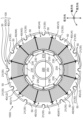
- FIG. 1 is a plan view of a motor according to an embodiment, as viewed from the axial direction.
- FIG. 2 is a plan view of a main portion of the stator as viewed from the axial direction.
- FIG. 3A is a perspective view of a main part of the stator as viewed from above.
- FIG. 3B is a perspective view of the main part of the stator as viewed from above.
- FIG. 3C is a perspective view of the main part of the stator as viewed from below.
- FIG. 3D is a perspective view of the main part of the stator as viewed from below.
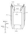
- FIG. 4A is a plan view of the insulating sheet in an unfolded state.
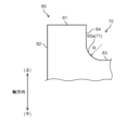
- FIG. 4B is an enlarged view of the area enclosed by the dashed line in FIG. 4A.
- FIG. 5 is a schematic diagram comparing a main part of the insulating sheet according to the embodiment with a main part of an insulating sheet according to a comparative example.
- FIG. 6 is a plan view of a main part of an insulating sheet according to a modified example.
- Fig. 1 is a plan view of a motor according to this embodiment as viewed from the axial direction, in which the illustration and description of connecting wires between coils 40 and external terminals that serve as connection portions to an external power source are omitted.
- the radial direction of motor 1000 is sometimes referred to as the "radial direction”, the outer circumferential direction as the “circumferential direction”, and the direction in which rotating shaft 220 of motor 1000 extends (the direction perpendicular to the paper surface in FIG. 1), in this case the longitudinal direction of rotating shaft 220 as the "axial direction”.
- the center side of motor 1000 is sometimes referred to as the radially inner side, and the outer circumferential side as the radially outer side.
- the side on which split insulator 51 (see FIG. 3A) is arranged on tooth 10 is sometimes referred to as the top or upper side
- the side on which split insulator 52 (see FIG. 3C) is arranged is sometimes referred to as the bottom or lower side.
- the motor 1000 has at least a stator 100 and a rotor 200.
- the motor 1000 has other components, such as bearings that support the rotating shaft 220 and a motor case, but for the sake of convenience, these are not shown or described.
- the motor 1000 is a so-called inner rotor type motor, but is not limited to this and may be an outer rotor type motor.
- the stator 100 has at least a stator core 30, a plurality of coils 40, an insulator 50, and an insulating sheet 60 (see FIG. 2).
- the stator core 30 is composed of an annular yoke 20 and a plurality of teeth 10 (see FIG. 2).
- the teeth 10 are spaced apart at equal angular intervals along the inner circumference (inner surface) of the yoke 20.
- the yoke 20 is an annular member formed by connecting a plurality of split yokes 21 (see FIG. 2) in the circumferential direction. Both the teeth 10 and the split yokes 21 are made of a magnetic material.
- the split yokes 21 on which the teeth 10 are provided may also be referred to as the stator core 30.
- the yoke 20 is formed by connecting multiple split yokes 21 in the circumferential direction.
- the stator core 30 may be formed by integrating the annular yoke 20 with multiple teeth 10.
- the space surrounded by the inner surfaces of the circumferentially adjacent stator cores 30 is configured as a slot 31 (see FIG. 2), and a coil 40 is housed in each of the multiple slots 31.
- the stator 100 is disposed radially outward of the rotor 200 at a fixed distance from the rotor 200.
- the coil 40 is a component made of wound conductor wire with an insulating coating (not shown) formed on its surface.
- the coil 40 is attached to the stator core 30 with an insulating sheet 60 and an insulator 50 sandwiched between them, and is housed in the slot 31. It can also be said that the coil 40 is attached to each of the multiple teeth 10 with the insulating sheet 60 sandwiched between them.
- the coils 40 may be referred to as coils U1 to U4, V1 to V4, and W1 to W4, respectively.
- the insulator 50 is a component made of insulating material attached to the stator core 30, and together with the insulating sheet 60, electrically separates the coil 40 from the stator core 30. Note that in this embodiment, split insulators 51, 52 split into two in the axial direction are used as the insulator 50 (see Figures 2 and 3A to 3D), but it does not have to be split.
- An insulating sheet 60 is provided between the coil 40 and the stator core 30 (see Figure 2 and Figures 3A to 3D).
- the insulating sheet 60 is made by processing insulating paper or a resin insulating sheet into a predetermined shape. The shape of the insulating sheet 60 will be described later.
- the rotor 200 has a rotor core 210, a rotating shaft 220, and a magnet 230.
- the rotor core 210 has a through hole at its axis and is generally cylindrical.
- the rotating shaft 220 is inserted into the through hole of the rotor core 210.
- the magnets 230 are arranged with their north and south poles alternating along the outer periphery of the rotor core 210, facing the stator 100.
- the coils U1 to U4, V1 to V4, and W1 to W4 are connected in series. Three-phase currents of U, V, and W phases, which have a phase difference of 120° electrical angle from each other, are supplied to the coils U1 to U4, V1 to V4, and W1 to W4, respectively, to excite them and generate a rotating magnetic field in the stator 100.
- This rotating magnetic field interacts with the magnetic field generated by the magnet 230 provided in the rotor 200, generating a torque in the rotor 200, and the rotating shaft 220 rotates while being supported by bearings (not shown).
- FIG. 2 shows a plan view of the main parts of the stator as viewed from the axial direction.
- FIGS. 3A and 3B show perspective views of the main parts of the stator as viewed from above.
- FIGS. 3C and 3D show perspective views of the main parts of the stator as viewed from below.
- FIG. 4A shows a plan view of the insulating sheet in an unfolded state.
- FIG. 4B shows an enlarged view of the part surrounded by the dashed line in FIG. 4A.
- the coil 40 is shown by a dashed line to make it easier to understand the structure of the stator core 30 and the insulating sheet 60.
- the coil 40 is not shown in FIGS. 3A and 3B.
- the split insulator 51 is not shown in FIG. 3B.
- the split insulator 52 is not shown in FIG. 3D.
- the insulating sheet 60 is folded and accommodated inside the slot 31.
- the insulating sheet 60 covers the inner surface of the stator core 30, specifically, the circumferential side surfaces of the teeth 10 and the radial inner surface of the split yoke 21.
- the coil 40 wound around the tooth 10 is accommodated inside the space (slot 31) surrounded by the insulating sheet 60.
- the insulating sheet 60 electrically insulates the coil 40 from the stator core 30.
- two coils 40 are housed adjacent to each other, each partially in one slot 31.
- the insulating sheet 60 also provides electrical insulation between adjacent coils 40 inside the slot 31.
- the split insulators 51 and 52 sandwich the insulating sheet 60 and each cover the axial end surface of the stator core 30.
- the split insulator 51 has a coil winding portion 51a, a flange portion 51b located on the radially outer side, and a flange portion 51c located on the radially inner side.
- grooves 51b1 and 51c1 are formed in the flange portions 51b and 51c, respectively.
- the grooves 51b1 and 51c1 are connected to form a groove portion.
- the third to seventh sides 63, 64, 65, 66, and 67 included in one cutout 70 of the insulating sheet 60 are each sandwiched in the groove portion connected from the groove 51b1 to the groove 51c1.
- the split insulator 52 has a coil winding portion 52a, a flange portion 52b located on the radially outer side, and a flange portion 52c located on the radially inner side.
- grooves 52b1 and 52c1 are formed in the flange portions 52b and 52c, respectively.
- the grooves 52b1 and 52c1 are connected to form a groove portion.
- the third to seventh sides 63, 64, 65, 66, and 67 included in the other notch 70 of the insulating sheet 60 are each sandwiched in the groove portion connected from the groove 52b1 to the groove 52c1.
- the insulating sheet 60 is sandwiched between a groove portion that connects groove 51b1 to groove 51c1 in split insulator 51 and a groove portion that connects groove 52b1 to groove 52c1 in split insulator 52. In this way, the position of the insulating sheet 60 is fixed relative to the split insulators 51 and 52.
- the coil 40 is attached to the stator core 30 in contact with the surfaces of the coil winding portions 51a, 52a of the split insulators 51, 52.
- the insulating sheet 60 in an unfolded state is a sheet material that is H-shaped in plan view.
- a notch 70 is formed toward the inside (inner side) of the insulating sheet 60 on each of two opposing sides (hereinafter referred to as first sides 61) of the sheet that is rectangular in plan view.
- first sides 61 two opposing sides
- the second side 62 of the insulating sheet 60 that is perpendicular to the first side 61 is parallel to the axial direction.
- orthogonal or parallel means orthogonal or parallel including the manufacturing tolerances and assembly tolerances of the components that make up motor 1000, and does not mean that the objects being compared are orthogonal or parallel in the strict sense.
- the notch 70 of the insulating sheet 60 includes a third side 63, a fourth side 64, and a first corner portion 71.
- the third side 63 is parallel to the first side 61.
- the fourth side 64 is continuous with the first side 61 and parallel to the second side 62.
- the first angle ⁇ 1 may be any angle less than or equal to 90 degrees ( ⁇ 1 ⁇ 90).
- the first corner portion 71 is provided at the intersection of the third side 63 and the fourth side 64.
- the second angle ⁇ 2 is not limited to 45 degrees, and may be any angle greater than 0 degrees and smaller than the first angle ⁇ 1 (0 ⁇ ⁇ 2 ⁇ ⁇ 1).
- the notch 70 of the insulating sheet 60 includes a third side 63, a seventh side 67, and a second corner portion 72.
- the fourth angle ⁇ 4 may be any angle less than or equal to 90 degrees ( ⁇ 4 ⁇ 90).
- the second corner portion 72 is provided at the intersection of the third side 63 and the seventh side 67.
- the third angle ⁇ 3 is not limited to 45 degrees, and may be any angle greater than 0 degrees and smaller than the fourth angle ⁇ 4 (0 ⁇ ⁇ 3 ⁇ ⁇ 4).
- a location 71a where one end of the third side 63 meets one end of the fifth side 65 may be referred to as a first portion 71a.
- a location 71b where the other end of the fifth side 65 meets one end of the fourth side 64 may be referred to as a second portion 71b.
- a location 71c where the other end of the fourth side 64 meets one end of the first side 61 may be referred to as a third portion 71c.
- the location 72a where the other end of the third side 63 meets one end of the sixth side 66 may be referred to as the fourth portion 72a.
- the location 72b where the other end of the sixth side 66 meets one end of the seventh side 67 may be referred to as the fifth portion 72b.
- the location 72c where the other end of the seventh side 67 meets one end of the first side 61 may be referred to as the sixth portion 72c.
- the notch 70 i.e., the third side 63, the fourth side 64, the seventh side 67, the first corner portion 71, and the second corner portion 72, protrude from the axial end face of the stator core 30 and are disposed outside the slot 31.
- the first corner portion 71 of the insulating sheet 60 is disposed radially outward in the stator 100.
- the second corner portion 72 of the insulating sheet 60 is disposed on the side closer to the tip of the stator core 30, i.e., on the radially inward side in the stator 100.
- the insulating sheet 60 has an asymmetric shape with respect to the center line O1-O2 extending in the axial direction. This is because the shape of the slot 31 differs between the radially inner and outer sides as shown in FIG. 2. In other words, the asymmetry of the shape of the insulating sheet 60 with respect to the center line O1-O2 extending in the axial direction can be changed as appropriate depending on the shape of the slot 31. In other words, the shape of the insulating sheet 60 may be symmetric with respect to the center line O1-O2.
- the insulating sheet 60 protruding outside the slot 31 may be further folded to cover the axial end face of the coil 40.
- the insulating sheet 60 As described above, the insulating sheet 60 according to this embodiment is attached to the stator core 30 of the motor 1000 .
- the insulating sheet 60 is a sheet material that is H-shaped in plan view, with inward-facing notches 70 formed on each of the two opposing first sides 61.
- the notch 70 has a first corner portion 71 and a second corner portion 72.
- the first corner portion 71 is formed at the intersection of the third side 63 and the fourth side 64.
- the third side 63 is parallel to the first side 61 and is located more inward than the first side 61.
- the fourth side 64 is inclined at a first angle ⁇ 1 with respect to the third side 63.
- the first corner portion 71 has a fifth side 65 that is inclined at a second angle ⁇ 2 of less than 90 degrees relative to the third side 63 in a plan view.
- the stator 100 has at least a stator core 30, slots 31, coils 40, and an insulating sheet 60.
- the stator core 30 has an annular yoke 20 and a number of teeth 10 spaced apart at equal angular intervals on the inner surface of the yoke 20.
- the slots 31 are spaces surrounded by the inner surfaces of adjacent stator cores 30.
- the coils 40 are attached to each of the multiple teeth 10 with the insulating sheet 60 sandwiched between them.
- the insulating sheet 60 is accommodated in the slot 31 in a folded state.
- the notch 70 in the insulating sheet 60 protrudes from the axial end face of the stator core 30 and is positioned outside the slot 31.
- the insulation distance (creepage distance) between the axial end face of the stator core 30 and the portion of the coil 40 that abuts against the fifth side 65 (edge) of the first corner portion is constant.
- FIG. 5 shows a schematic diagram comparing the main parts of the insulating sheet according to the embodiment with the main parts of the insulating sheet according to the comparative example.
- the diagram on the left side of FIG. 5 shows the insulating sheet 60 of the embodiment, and the diagram on the right side shows the insulating sheet 80 according to the comparative example.
- the insulating sheet 80 corresponds to the thin insulating material shown in Patent Document 1.
- the coil 40 is wound around the stator core 30, sandwiched between the insulating sheet 60 and the split insulator 51 or split insulator 52.
- the insulation distance between the coil 40 and the stator core 30 corresponds to the boundary between the insulating sheet 60 and the coil 40 exposed from the insulating sheet 60, i.e., the distance between the fifth side 65 of the insulating sheet 60 and the axial end face of the stator core 30.
- This distance i.e., the insulation distance, is shown by line segments A1-A2, B1-B2, and C1-C2 on the left side of Figure 5.
- the length of the line segment B1-B2 corresponds to the sum of the length of the line segment drawn from point B1 located on the extension of the fourth side 64 parallel to the third side 63 to the fifth side 65, and the length of the line segment drawn from the fifth side 65 parallel to the fourth side 64 to the axial end face of the stator core 30.
- the length of the line segment C1-C2 corresponds to the sum of the length of the line segment drawn from C1, located at the extension of the fourth side 64, parallel to the third side 63 to the fifth side 65, and the length of the line segment drawn from the fifth side 65 parallel to the fourth side 64 to the axial end face of the stator core 30.
- the fifth side 65 constituting the first corner portion 71 is inclined with respect to the third side 63 at a second angle ⁇ 2 ( ⁇ 2 ⁇ 90) that is smaller than the first angle ⁇ 1. Therefore, the aforementioned insulation distance at the first corner portion 71 is constant.
- the third side 83 and the fourth side 84 intersect perpendicularly, so that the first corner portion 91 forms a right angle.
- the first side 81 of the insulating sheet 80 corresponds to the first side 61 of the insulating sheet 60
- the second side 82 of the insulating sheet 80 corresponds to the second side 62 of the insulating sheet 60.
- the insulation distance between the coil 40 and the stator core 30 is the length of the line segment D1-D2 shown on the right side of FIG. 5.
- the axial height does not change continuously, as in the first corner portion 71 of the insulating sheet 60 shown on the left side of FIG. 5.
- the length of the line segment D1-D2 is longer than the length of the line segment A1-A2 by ⁇ H.
- a similar condition occurs in the notch 90 provided on the other side in the axial direction.
- the axial length of the stator 100 becomes longer by 2 ⁇ H compared to the case shown in this embodiment. This increases the axial size of the stator 100, and therefore the motor 1000, which is an obstacle to miniaturization of the stator 100 and the motor 1000.
- the size of the stator 100 and the motor 1000 can be prevented from increasing in the axial direction, and the motor 1000 can be made smaller.
- the insulation distance between the coil 40 and the stator core 30 can be guaranteed, so that the reliability of the motor 1000 during operation can be prevented from decreasing.
- the sixth side 66 constituting the second corner portion 72 of the insulating sheet 60 also forms a third angle ⁇ 3 with respect to the third side 63.
- the insulating sheet 60 can prevent the size of the stator 100, and therefore the motor 1000, from increasing in the axial direction while ensuring the insulation distance between the coil 40 and the stator core 30 even at the second corner portion 72.
- the fifth side 65 constituting the first corner portion 71 is preferably a straight line in a plan view. In this way, as described above, it is possible to ensure that the insulation distance between the coil 40 and the stator core 30 is equal to or greater than a predetermined value throughout the entire first corner portion 71. For the same reason, the sixth side 66 constituting the second corner portion 72 is preferably a straight line in a plan view.
- the second angle ⁇ 2 and the third angle ⁇ 3 are not limited to 45 degrees.
- the preferred ranges for the second angle ⁇ 2 and the third angle ⁇ 3 are 30 degrees or more and 60 degrees or less (30 ⁇ 2 ⁇ 60, 30 ⁇ 3 ⁇ 60).
- the insulation distance becomes shorter, so it becomes necessary to maintain the insulation distance by increasing the length of the insulating sheet 60 and increasing the height of the insulator 50 (split insulators 51, 52). Therefore, the total axial length of the assembly part of the stator 100, that is, the part where the insulator 50, the stator core 30, and the insulating sheet 60 are integrated, becomes longer, and as a result, the motor 1000 becomes larger.
- the second angle ⁇ 2 and the third angle ⁇ 3 are set to 30 degrees or more and 60 degrees or less, respectively, it is possible to ensure the insulation distance between the coil 40 and the stator core 30.
- the increase in the length of the insulating sheet 60 and the height of the insulator 50 can be suppressed, and the motor 1000 can be made smaller.
- the second angle ⁇ 2 is 45 degrees.
- the insulation distance between the coil 40 and the stator core 30 can be made constant and maximized throughout the entire first corner portion 71.
- the third angle ⁇ 3 is 45 degrees at the second corner portion 72.
- the second angle ⁇ 2 needs only to be smaller than the first angle ⁇ 1. In this way, the axial height of the first corner portion 71 can be reduced while still ensuring the aforementioned insulation distance.
- the third angle ⁇ 3 needs only to be smaller than the fourth angle ⁇ 4.
- the motor 1000 includes at least a stator 100 and a rotor 200 arranged at a predetermined radial distance from the stator 100.
- the insulation distance between the coil 40 and the stator core 30 can be guaranteed while preventing the size of the stator 100, and therefore the motor 1000, from increasing in the axial direction. This allows the motor 1000 to be made smaller and its reliability during operation to be improved.
- Fig. 6 is a plan view of a main part of an insulating sheet according to a modified example.
- the same reference numerals are used for the same parts as those in the first embodiment, and detailed explanations thereof will be omitted.
- the insulating sheet 60 of this modified example shown in FIG. 6 differs from the insulating sheet 60 of the embodiment shown in FIGS. 4A and 4B in that the fifth side 65a constituting the first corner portion 71 is rounded into an arc shape having a radius of curvature (first radius of curvature) R.
- the insulating sheet 60 may be configured in this manner, and the same effects as those achieved by the configuration shown in the embodiment can be achieved. In other words, the insulation distance between the coil 40 and the stator core 30 can be ensured, while preventing the size of the stator 100, and therefore the motor 1000, from increasing in the axial direction. This allows the motor 1000 to be made more compact, and increases its reliability during operation.
- the fifth side 65a may be an elliptical arc shape.
- the sixth side 66 may be in the shape of a circular arc or an elliptical arc having a radius of curvature R.
- the stator 100 in this specification is configured to use an insulating sheet 60 so that the insulation distance between the axial end face of the stator core 30 and the portion of the coil 40 that abuts against the edge (fifth side 65 or fifth side 65a) of the first corner portion 71 is constant.
- stator 100 is configured with an insulating sheet 60 so that the insulation distance between the axial end face of the stator core 30 and the portion of the coil 40 that abuts against the edge (sixth side 66) of the second corner portion 72 is constant.
- the motor 1000 is a three-phase AC motor
- the present invention is not particularly limited to this.
- the motor 1000 may be a DC motor.
- the number of poles of the motor 1000 (the total number of poles of the magnets 230), the number of slots 31, and further the number of phases of the motor 1000 may be appropriately changed depending on the application of the motor 1000, etc.
- the stator core 30 and rotor core 210 are each made of a magnetic material, and the materials are selected appropriately according to the specifications of the motor 1000.
- the insulating sheet may be an insulating sheet formed by appropriately combining partial configurations of the insulating sheet according to the embodiments and modified examples.
- the materials, numerical values, etc. described in the embodiments are merely preferred examples, and are not limited thereto.
- the insulating sheet disclosed herein is useful because it can prevent the stator, and therefore the motor, from increasing in size in the axial direction while maintaining the insulation distance between the coil and the stator core.
Landscapes
- Engineering & Computer Science (AREA)
- Power Engineering (AREA)
- Insulation, Fastening Of Motor, Generator Windings (AREA)
- Iron Core Of Rotating Electric Machines (AREA)
Priority Applications (2)
| Application Number | Priority Date | Filing Date | Title |
|---|---|---|---|
| CN202380069357.2A CN119923786A (zh) | 2022-10-21 | 2023-09-14 | 绝缘片以及具备该绝缘片的定子、马达 |
| JP2024551340A JPWO2024084869A1 (https=) | 2022-10-21 | 2023-09-14 |
Applications Claiming Priority (2)
| Application Number | Priority Date | Filing Date | Title |
|---|---|---|---|
| JP2022169048 | 2022-10-21 | ||
| JP2022-169048 | 2022-10-21 |
Publications (1)
| Publication Number | Publication Date |
|---|---|
| WO2024084869A1 true WO2024084869A1 (ja) | 2024-04-25 |
Family
ID=90737508
Family Applications (1)
| Application Number | Title | Priority Date | Filing Date |
|---|---|---|---|
| PCT/JP2023/033549 Ceased WO2024084869A1 (ja) | 2022-10-21 | 2023-09-14 | 絶縁シート及びそれを備えた固定子、モータ |
Country Status (4)
| Country | Link |
|---|---|
| JP (1) | JPWO2024084869A1 (https=) |
| CN (1) | CN119923786A (https=) |
| TW (1) | TWI872735B (https=) |
| WO (1) | WO2024084869A1 (https=) |
Cited By (1)
| Publication number | Priority date | Publication date | Assignee | Title |
|---|---|---|---|---|
| CN118199305A (zh) * | 2024-05-15 | 2024-06-14 | 库卡机器人(广东)有限公司 | 绝缘片、定子组件、电机、伺服系统及工业机器人 |
Citations (4)
| Publication number | Priority date | Publication date | Assignee | Title |
|---|---|---|---|---|
| JP2003061286A (ja) * | 2001-08-17 | 2003-02-28 | Matsushita Electric Ind Co Ltd | 固定子の製造方法およびその固定子を用いた電動機 |
| JP2008206322A (ja) * | 2007-02-21 | 2008-09-04 | Mitsubishi Electric Corp | 電機子の絶縁シートおよび電機子 |
| JP2010045868A (ja) * | 2008-08-08 | 2010-02-25 | Nidec Sankyo Corp | モータ |
| WO2014125607A1 (ja) * | 2013-02-15 | 2014-08-21 | 三菱電機株式会社 | 回転電機の固定子 |
Family Cites Families (5)
| Publication number | Priority date | Publication date | Assignee | Title |
|---|---|---|---|---|
| JP5306411B2 (ja) * | 2011-05-23 | 2013-10-02 | 三菱電機株式会社 | 回転電機 |
| TWM437000U (en) * | 2012-03-29 | 2012-09-01 | Mirle Automation Corp | Insulation assembly for a motor stator |
| CN203883563U (zh) * | 2014-06-05 | 2014-10-15 | 常州市武进金宝电机有限公司 | 拼装式电机定子单元 |
| WO2021205708A1 (ja) * | 2020-04-07 | 2021-10-14 | 日立Astemo株式会社 | 回転電機の固定子 |
| TWM613101U (zh) * | 2021-01-15 | 2021-06-11 | 士林電機廠股份有限公司 | 馬達定子繞線架結構 |
-
2023
- 2023-09-14 JP JP2024551340A patent/JPWO2024084869A1/ja active Pending
- 2023-09-14 WO PCT/JP2023/033549 patent/WO2024084869A1/ja not_active Ceased
- 2023-09-14 CN CN202380069357.2A patent/CN119923786A/zh active Pending
- 2023-10-11 TW TW112138669A patent/TWI872735B/zh active
Patent Citations (4)
| Publication number | Priority date | Publication date | Assignee | Title |
|---|---|---|---|---|
| JP2003061286A (ja) * | 2001-08-17 | 2003-02-28 | Matsushita Electric Ind Co Ltd | 固定子の製造方法およびその固定子を用いた電動機 |
| JP2008206322A (ja) * | 2007-02-21 | 2008-09-04 | Mitsubishi Electric Corp | 電機子の絶縁シートおよび電機子 |
| JP2010045868A (ja) * | 2008-08-08 | 2010-02-25 | Nidec Sankyo Corp | モータ |
| WO2014125607A1 (ja) * | 2013-02-15 | 2014-08-21 | 三菱電機株式会社 | 回転電機の固定子 |
Cited By (1)
| Publication number | Priority date | Publication date | Assignee | Title |
|---|---|---|---|---|
| CN118199305A (zh) * | 2024-05-15 | 2024-06-14 | 库卡机器人(广东)有限公司 | 绝缘片、定子组件、电机、伺服系统及工业机器人 |
Also Published As
| Publication number | Publication date |
|---|---|
| TWI872735B (zh) | 2025-02-11 |
| CN119923786A (zh) | 2025-05-02 |
| TW202418715A (zh) | 2024-05-01 |
| JPWO2024084869A1 (https=) | 2024-04-25 |
Similar Documents
| Publication | Publication Date | Title |
|---|---|---|
| JP5361277B2 (ja) | モータ | |
| JP6533831B2 (ja) | 回転電機 | |
| US20230291265A1 (en) | Electrical insulator, stator and motor | |
| US12142982B2 (en) | Stator and rotary electric machine | |
| JP6720306B2 (ja) | 回転電機の固定子 | |
| CN111164860B (zh) | 旋转电机的定子 | |
| JP6760227B2 (ja) | 回転電機のステータ | |
| JPWO2019058643A1 (ja) | インシュレータ及びそれを備えたステータ、モータ | |
| JP2012075213A (ja) | ステータ | |
| JP2019030158A (ja) | 回転電機のステータ | |
| JP6293576B2 (ja) | 回転電機用のステータ | |
| WO2024084869A1 (ja) | 絶縁シート及びそれを備えた固定子、モータ | |
| JP7342654B2 (ja) | 回転電機 | |
| JP2014207785A (ja) | モータ | |
| JP6279122B1 (ja) | 回転電機 | |
| CN112272913B (zh) | 电动机及用于该电动机的线圈 | |
| JP2023048366A (ja) | ステータ、及び、回転電機 | |
| US20240186843A1 (en) | Motor | |
| JP2025087515A (ja) | ステータ | |
| JP7264021B2 (ja) | スロットレス回転電機 | |
| EP4648263A1 (en) | Stator structure of rotating electric machine | |
| JP2025087516A (ja) | ステータ | |
| JP2025095743A (ja) | ステータおよびモータ | |
| JP2025095742A (ja) | ステータおよびモータ | |
| JP2025095741A (ja) | ステータおよびモータ |
Legal Events
| Date | Code | Title | Description |
|---|---|---|---|
| 121 | Ep: the epo has been informed by wipo that ep was designated in this application |
Ref document number: 23879519 Country of ref document: EP Kind code of ref document: A1 |
|
| WWE | Wipo information: entry into national phase |
Ref document number: 2024551340 Country of ref document: JP |
|
| WWE | Wipo information: entry into national phase |
Ref document number: 202380069357.2 Country of ref document: CN |
|
| WWP | Wipo information: published in national office |
Ref document number: 202380069357.2 Country of ref document: CN |
|
| NENP | Non-entry into the national phase |
Ref country code: DE |
|
| 122 | Ep: pct application non-entry in european phase |
Ref document number: 23879519 Country of ref document: EP Kind code of ref document: A1 |