WO2024084657A1 - 圧縮機、冷凍サイクル装置及び回転子 - Google Patents
圧縮機、冷凍サイクル装置及び回転子 Download PDFInfo
- Publication number
- WO2024084657A1 WO2024084657A1 PCT/JP2022/039112 JP2022039112W WO2024084657A1 WO 2024084657 A1 WO2024084657 A1 WO 2024084657A1 JP 2022039112 W JP2022039112 W JP 2022039112W WO 2024084657 A1 WO2024084657 A1 WO 2024084657A1
- Authority
- WO
- WIPO (PCT)
- Prior art keywords
- gap
- rotor
- layer
- end surface
- rotation axis
- Prior art date
- Legal status (The legal status is an assumption and is not a legal conclusion. Google has not performed a legal analysis and makes no representation as to the accuracy of the status listed.)
- Ceased
Links
Images


Classifications
-
- H—ELECTRICITY
- H02—GENERATION; CONVERSION OR DISTRIBUTION OF ELECTRIC POWER
- H02K—DYNAMO-ELECTRIC MACHINES
- H02K1/00—Details of the magnetic circuit
- H02K1/06—Details of the magnetic circuit characterised by the shape, form or construction
- H02K1/22—Rotating parts of the magnetic circuit
-
- H—ELECTRICITY
- H02—GENERATION; CONVERSION OR DISTRIBUTION OF ELECTRIC POWER
- H02K—DYNAMO-ELECTRIC MACHINES
- H02K7/00—Arrangements for handling mechanical energy structurally associated with dynamo-electric machines, e.g. structural association with mechanical driving motors or auxiliary dynamo-electric machines
- H02K7/04—Balancing means
Definitions
- This disclosure relates to a compressor, a refrigeration cycle device, and a rotor.
- balance weights In electric motors for compressors, a known configuration is to install balance weights on the axial end faces of the rotor to reduce the imbalance of centrifugal forces generated in the compression mechanism. Balance weights impose dimensional constraints when increasing the output of electric motors or making them smaller, so it is preferable for them to be as small as possible.
- a known method for miniaturizing balance weights is to create a weight imbalance in the rotor by providing an air gap in the rotor core that is asymmetric with respect to the center of rotation, thereby eliminating the need for balance weights (for example, Patent Document 1).
- the rotor described in the prior art document does not have any gaps that would cause a weight imbalance penetrating in the axial direction, and the only path through which the refrigerant and lubricating oil pass through the motor section is the small gap between the rotor and stator. This can impede the movement of the refrigerant and lubricating oil, creating an unintended pressure difference inside the compressor and causing poor lubrication of the compression mechanism.
- This disclosure has been made to solve the problems described above, by miniaturizing the balance weight that offsets the imbalance of centrifugal forces that occur in the compression mechanism, and by obtaining a compressor equipped with an electric motor that ensures a flow path for the refrigerant and lubricating oil that moves inside the compressor.
- the compressor according to the present disclosure is a compressor including a sealed container, a compression mechanism unit built into the sealed container and compressing a refrigerant, a stator fixed inside the sealed container, and a rotor having a shaft serving as a rotating shaft, and an electric motor that drives the compression mechanism unit connected via the shaft, the rotor having a rotor core formed cylindrically around the rotating shaft, the rotor core including the rotating shaft, and when the rotor core is divided into a first core portion and a second core portion with a first plane that includes the rotating shaft and is parallel to the rotating shaft as a boundary surface, the first core portion has a first gap that penetrates from one end face to the other end face in the axial direction, and the second core portion has a second gap that penetrates from one end face to the other end face in the axial direction, and in a cross section perpendicular to the rotating shaft, the cross-sectional area of the second gap is smaller than the cross-sectional area of the first gap.
- the compressor disclosed herein has a gap that penetrates the rotor in the axial direction, which allows the use of a smaller balance weight to offset the imbalance of centrifugal forces generated in the compression mechanism, and also inhibits the movement of refrigerant and lubricating oil inside the compressor, suppressing the occurrence of unintended pressure differences.
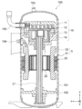
- FIG. 1 is a cross-sectional view showing a configuration of a compressor according to a first embodiment.
- 2 is a cross-sectional view showing the configuration of a rotor according to the first embodiment.
- FIG. 2 is a vertical cross-sectional view showing the configuration of a rotor according to the first embodiment.
- FIG. FIG. 2 is a perspective view showing the configuration of a rotor according to the first embodiment.
- 3 is a magnetic flux line diagram showing a schematic diagram of a magnetic flux flow inside a rotor core according to the first embodiment.
- FIG. FIG. 11 is a vertical cross-sectional view showing the configuration of a rotor according to a second embodiment.
- FIG. 11 is a cross-sectional view showing the configuration of a rotor according to a second embodiment.
- FIG. 11 is a vertical cross-sectional view showing the configuration of a rotor according to a third embodiment.
- FIG. 13 is a diagram showing the configuration of a refrigeration cycle device according to
- the z-axis is a coordinate axis parallel to axis C, which is the center of rotation of rotor 1.
- the x-axis is a coordinate axis perpendicular to the z-axis.
- the y-axis is a coordinate axis perpendicular to both the x-axis and the z-axis.
- FIG. 1 is a cross-sectional view showing the configuration of a compressor according to embodiment 1.
- the compressor 100 is a scroll type compressor, in which a compression mechanism 10, an electric motor 20, and a subframe 102 are housed in a sealed container 101.
- the compression mechanism 10 is a part that compresses the refrigerant.
- the electric motor 20 drives the compression mechanism 10.
- the electric motor 20 is connected to the compression mechanism 10 by a shaft 21.
- the electric motor 20 is, for example, a permanent magnet synchronous motor.
- the shaft 21 extends in the z-axis direction.
- the sealed container 101 is a container that houses the compression mechanism 10 and the electric motor 20.
- the sealed container 101 is equipped with a suction pipe 105 that draws refrigerant into the compression mechanism 10 from the outside, and a discharge pipe 103 that discharges the high-pressure refrigerant discharged from the compression mechanism 10 to the outside of the compressor 100.
- a glass terminal 104 that supplies power to the electric motor 20 is fixed to the sealed container 101.
- the glass terminal 104 is fixed to the sealed container 101 by, for example, welding.
- the subframe 102 supports the end of the shaft 21 of the electric motor 20 on the -z axis side.
- the compression mechanism 10 is composed of a fixed scroll 11, an orbiting scroll 12, a compliance frame 13, and a guide frame 14.
- a compression chamber is formed by meshing the spiral portion of the fixed scroll 11 with the spiral portion of the orbiting scroll 12.
- the compliance frame 13 supports the end of the shaft 21 on the +z axis side.
- the guide frame 14 is fixed to the sealed container 101 and supports the compliance frame 13.
- the electric motor 20 is composed of a rotor 1 and a stator 5.
- the stator 5 has a stator core 51 and windings 52 wound around the teeth (not shown) of the stator core 51.
- the rotation of the electric motor 20 is transmitted to the oscillating scroll 12 through the shaft 21.
- the compression mechanism 10 changes the volume of the compression chamber by the oscillation of the oscillating scroll 10, and compresses the refrigerant flowing in from the suction pipe 105.
- the compressed refrigerant flows out of the compressor 100 from the discharge pipe 103.
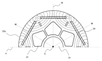
- Fig. 2 is a cross-sectional view showing the configuration of the rotor 1 according to the first embodiment.
- Fig. 3 is a vertical-sectional view showing the configuration of the rotor 1 according to the first embodiment.
- Fig. 4 is a perspective view showing the configuration of the rotor 1 according to the first embodiment.
- Fig. 4 is a view excluding the shaft 21.
- the rotor 1 has the shaft 21 as a rotation axis, a rotor core 22 formed in a cylindrical shape centered on the rotation axis, a balance weight 23 provided on the rotor core 22, and a permanent magnet 24. Note that the balance weight 23 is not shown in Fig. 2.
- the direction along the circumference of a circle centered on the axis C of shaft 21 is called the “circumferential direction R”
- the direction in which shaft 21 extends is called the "axial direction”
- the direction in which a straight line passing through shaft 21 perpendicular to the axial direction extends is called the "radial direction”.
- a "transverse cross-sectional view” is a cross-sectional view cut along a plane perpendicular to axis C
- a “longitudinal cross-sectional view” is a cross-sectional view cut along a plane parallel to axis C.
- the balance weight 23 is provided to offset the imbalance of the centrifugal force generated by the rotation of the shaft 21, which has an eccentric part for oscillating the oscillating scroll 12.
- the balance weight 23 is made of a non-magnetic material such as brass.
- the cross section of the rotor 1 is approximately circular, and the shaft 21 is disposed at the center of rotation.
- the rotor 1 is composed of a rotor core 22 with a shaft insertion hole 34 at the center of rotation, and the shaft 21 inserted into the shaft insertion hole 34.
- the rotor core 22 has multiple (e.g., six) magnet insertion holes 25 spaced equally apart in the circumferential direction R.
- a permanent magnet 24 is inserted into each of the magnet insertion holes 25. Since one permanent magnet 24 forms one magnetic pole, the rotor 1 shown in this embodiment 1 has six poles. In this way, the rotor 1 is a permanent magnet embedded rotor. Note that the number of poles of the rotor 1 is not limited to six, and may be two or more. Furthermore, multiple permanent magnets 24 may be inserted into one magnet insertion hole 25.
- the permanent magnet 24 is, for example, a rare earth magnet, specifically, a neodymium sintered magnet containing neodymium (Nd), iron (Fe) and boron (B). Note that the permanent magnet 24 is not limited to a neodymium sintered magnet, and may be, for example, any one of a samarium cobalt magnet, a ferrite magnet and a bonded magnet.
- the rotor 22 also has multiple flux barriers 25a.
- the multiple flux barriers 25a are part of the magnet insertion hole 25 and are formed at both ends of the magnet insertion hole 25.
- the flux barriers 25a form thin sections near the outer circumferential surface of the rotor core 22, so that short circuits of the magnetic flux of the permanent magnets 24 between adjacent magnetic poles in the circumferential direction R can be suppressed.
- the rotor core 22 is formed by stacking multiple electromagnetic steel sheets in the z-axis direction.
- the thickness of each electromagnetic steel sheet is set to a range of 0.1 mm to 0.5 mm, for example. In the first embodiment, the thickness of each electromagnetic steel sheet is 0.35 mm.
- the multiple electromagnetic steel sheets are fixed to each other by crimping. Therefore, the rotor core 22 has multiple crimped portions 33.
- the rotor core 22 is divided into a first core portion 22a and a second core portion 22b by an imaginary plane V that includes the axis C, which is a first plane.
- the imaginary plane V that divides the first core portion 22a and the second core portion 22b is called the reference plane V.
- the first core portion 22a is provided with a first gap 31 that penetrates the rotor core 22 in the z-axis direction.
- the second core portion 22b is provided with a second gap 32 that penetrates the rotor core 22 in the z-axis direction and has a smaller cross-sectional area than the first gap 31.
- the first gap 31 and the second gap 32 are formed by holes provided in the electromagnetic steel plates.
- the right half of the page is the first core portion 22a
- the left half is the second core portion 22b, with the reference plane V as the boundary.
- the first core portion 22a has a larger air gap than the second core portion 22b, and therefore is lighter in weight than the second core portion 22b.
- the center of gravity of the rotor core 22 is biased toward the second core portion 22b.
- End plates 26 are fixed to both sides of the axial end face of the rotor core 22. As shown in Figures 3 and 4, the end plates 26 are provided with communication holes 27 so that the first gap 31 and the second gap 32 are not blocked.
- the communication holes 27 are either of the same shape as the first gap 31 or are larger than the first gap 31, and are formed to contain the first gap 31 and the second gap 32.
- a balance weight 23 is fixed to the second core portion 22b via an end plate 26.
- the balance weight 23 is installed so as to further increase the degree of eccentricity of the center of gravity caused by the weight difference between the first core portion 22a and the second core portion 22b.
- the position and weight of the balance weight 23 are determined by the degree of eccentricity of the compression mechanism 10 connected to the shaft 21, and are not limited to the position in this embodiment. In addition, if the weight imbalance on the rotor core 22 can completely offset the centrifugal force imbalance caused in the compression mechanism 10, the balance weight 23 does not need to be installed.
- the balance weight 23 also has a through hole 35 formed therethrough in the z-axis direction so as to communicate with the first gap 31 or the second gap 32.
- the through hole 35 is formed so that the first gap 31 or the second gap 32 is not blocked even when the balance weight 23 is installed on the rotor core 22.
- Figure 5 is a magnetic flux line diagram that shows a schematic representation of the flow of magnetic flux inside the rotor core 22.
- the first core portion 22a shown in Figure 5 has three permanent magnets 24 extending in the circumferential direction R and three corresponding first air gaps 31. If the midpoint of each permanent magnet 24 in the circumferential direction R is defined as the magnetic pole center, then line M in Figure 5 is a straight line on the xy plane that connects the axis C and the magnetic pole center of each permanent magnet 24, and will hereinafter be referred to as the "magnetic pole center line.”
- the magnetic flux density inside the rotor core 22 is dense in the region between two adjacent permanent magnets 24 in the circumferential direction R, and is sparse near the magnetic pole center. Therefore, the region along the magnetic pole center line M plays a smaller role as a magnetic path than the region between adjacent permanent magnets 24 in the circumferential direction R.
- the gaps provided in the rotor core 22 hinder the flow of magnetic flux and increase iron loss.
- the eccentricity of the center of gravity of the rotor core 22 it is better for the eccentricity of the center of gravity of the rotor core 22 to be large.
- the cross-sectional area of the first gap 31 should be as large as possible without hindering the flow of magnetic flux in the rotor core 22.
- the cross-sectional area of the second gap 32 should be as small as possible without hindering the flow of refrigerant passing axially through the rotor core 22 within the sealed container 101.
- the side surface of the rotor 22 that forms the first gap 31 and is closest to the magnetic pole center on the magnetic pole center line M is formed so that the farther it is from the magnetic pole center line M in the circumferential direction R, the farther it is from the permanent magnet 24.
- the first gap 31 is formed in a convex shape toward the magnetic pole center, which is the midpoint of the circumferential direction R of the permanent magnet 24.
- the first core portion 22a by giving the first gap 31 the shape described above, it can be formed as large as possible without affecting iron loss.
- the first core portion 22a in the rotor core 22 is provided with the first gap 31 penetrating in the z-axis direction
- the second core portion 22b is provided with the second gap 32 penetrating in the z-axis direction and having a smaller cross-sectional area than the first gap 31.
- first gap 31 and the second gap 32 which have different cross-sectional areas, create a weight imbalance in the rotor core 22, which can offset the imbalance in centrifugal force generated by the rotation of the compression mechanism 10.
- a balance weight 23 is installed to impart a weight imbalance to the rotor 1, thereby offsetting the imbalance of the centrifugal force generated by the rotation of the compression mechanism 10. In this case, since a weight imbalance occurs in the rotor core 22 due to the first gap 31 and the second gap 32, the balance weight 23 can be made smaller.
- the radially outer side of the first gap 31 is formed so as to be closest to the permanent magnet 24 on the magnetic pole center line M, and to be farther away from the permanent magnet 24 the further away it is from the magnetic pole center line M in the circumferential direction R.
- the electromagnetic steel sheets are laminated so that one side of the reference plane V is entirely the first core portion 22a and the other side is entirely the second core portion 22b, maximizing the weight imbalance of the rotor 1. This allows the balance weight 23 to be made even smaller.
- the compressor can be made lighter and smaller.
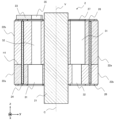
- Fig. 6 is a vertical cross-sectional view showing the configuration of a rotor 2 according to embodiment 2.
- components that are the same as or correspond to those shown in Fig. 3 are given the same reference numerals as those shown in Fig. 3.
- the rotor 2 according to embodiment 2 has an inversion plane H1, which is a second plane perpendicular to the z-axis, on the rotor core 22.
- the first core portion 22a is on the right side of the reference plane V including the axis C, and the second core portion 22b is on the left side.
- the second core portion 22b is on the right side of the reference plane V including the axis C, and the first core portion 22a is on the left side.
- the first layer above the inversion surface H1 is heavier on the left side of the reference plane V in FIG. 6 due to the weight difference between the first core portion 22a and the second core portion 22b and the balance weight 23.
- the second layer below the inversion surface H1 is heavier on the right side of the reference plane V in FIG. 6 due to the weight difference between the first core portion 22a and the second core portion 22b.
- a weight imbalance is also created in the z-axis direction.
- the weight imbalance in the z-axis direction can offset the even imbalance that causes the wobbly vibration of the shaft 21 caused by the rotation of the rotor 2.
- Figure 7 is a cross-sectional view showing the configuration of the rotor 2 according to embodiment 2.
- the first gap 31 and the second gap 32 formed in the first layer are shown by solid lines, and the first gap 31 and the second gap 32 formed in the second layer are shown by dashed lines.
- the first gap 31 is arranged to include the second gap 32. That is, in the rotor 2, the first gap 31 and the second gap 32 are connected from one end face to the other end face of the rotor core 22. Therefore, the movement of the refrigerant and lubricating oil inside the compressor 100 is not hindered by the rotor 2.
- the multiple magnet insertion holes 25 and crimped portions 33 provided in the electromagnetic steel sheets forming the rotor core 22 are arranged at equal pitches in the circumferential direction R so that they overlap in the same position even when the electromagnetic steel sheets are rotated 180 degrees around the axis C and stacked. Therefore, the insertion of the permanent magnets 24 and the stacking of the electromagnetic steel sheets can be carried out without any problems.
- the weight distribution of the rotor core 22 can also be adjusted in the z-axis direction, so that the even imbalance of the rotor 2 can also be offset. This allows the balance weight 23 to be made more compact.
- Even imbalance refers to the weight imbalance in the z-axis direction that causes a swinging motion when the rotor 2 is rotating.
- the first gap 31 and the second gap 32 are formed to communicate in the z-axis direction, so the movement of the refrigerant and lubricating oil within the compressor 100 is not impeded and the efficiency of the compressor is not reduced.
- the rotor 2 has a point-symmetric relationship between the first core portion 22a and the second core portion 22b that make up the rotor core 22, and electromagnetic steel sheets of the same shape are rotated 180 degrees and stacked, so there is no need to use multiple types of electromagnetic steel sheets. As a result, only one die is required to manufacture the electromagnetic steel sheets by punching, which reduces manufacturing costs.
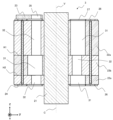
- Fig. 8 is a vertical cross-sectional view showing the configuration of a rotor 3 according to embodiment 3.
- the rotor 3 according to embodiment 3 has an inversion surface H2, which is a third plane, in parallel with an inversion surface H1, which is a surface perpendicular to the z-axis, on the rotor core 22.
- the upper side of the inversion surface H1, which is the first layer is the first core portion 22a on the right side of the reference plane V, and the second core portion 22b on the left side of the reference plane V.
- the lower side of the inversion surface H1, which is the second layer is further divided into upper and lower parts by the inversion surface H2, and the lower side of the inversion surface H2, which is the lower layer, is the first core portion 22a on the right side of the reference plane V, and the second core portion 22b on the left side, just like the first layer.
- the portion sandwiched between the inversion surfaces H1 and H2, which are the upper layers is the second core portion 22b on the right side of the reference plane V, and the first core portion 22a on the left side.
- the first gap 31 and the second gap 32 provided in the upper and lower layers of the first and second layers constituting rotor core 22 are arranged so as to penetrate rotor core 22 in the axial direction.
- the rotor 3 can be given an appropriate weight difference between the right and left sides of the reference plane V shown in FIG. 8, and the weight distribution in the z-axis direction can also be freely adjusted.
- Other functions are the same as those of the rotor 2 described in the second embodiment.
- the rotor 3 can adjust the weight distribution of the rotor core 22 more precisely than the rotor 2 described in the second embodiment, depending on the position of the inversion surfaces H1 and H2 in the z-axis direction. This allows the rotor 3 to position the center of gravity on the axis C and also offset the couple imbalance. This allows the balance weight 23 to be made smaller.
- the first gap 22a and the second gap 22b are formed to communicate with each other in the z-axis direction, so the flow of the refrigerant in the compressor 100 is not impeded and the efficiency of the compressor is not reduced.
- the first core portion 22a and the second core portion 22b that constitute the rotor core 22 are in a point-symmetrical relationship, so there is no need to use multiple types of electromagnetic steel sheets. Therefore, only one die is needed to manufacture the electromagnetic steel sheets by punching, which reduces manufacturing costs.
- Embodiment 4. 9 is a diagram showing a configuration of a refrigeration cycle apparatus 300 according to embodiment 4.
- a refrigeration cycle apparatus 300 including a refrigeration cycle including the compressor 100 described in embodiment 1 will be described.
- the refrigeration cycle device 300 is an air conditioning device equipped with an outdoor unit 71 and an indoor unit 72.
- the outdoor unit 71 and the indoor unit 72 are connected by a refrigerant pipe 73 to form a refrigerant circuit that is a closed circuit.
- This refrigerant circuit is filled with R32, an HFC refrigerant, as the working refrigerant.
- the refrigerant filled in this refrigerant circuit is not limited to R32, and may be R290, a natural refrigerant, or a mixed refrigerant containing carbon dioxide, etc.
- the outdoor unit 71 incorporates a compressor 100, an outdoor heat exchanger 74, an expansion valve 75, and an outdoor blower 76.
- the compressor 100 is equipped with an inverter device that continuously changes the operating frequency, making it possible to increase or decrease the flow rate of refrigerant circulating through the refrigerant circuit.
- the refrigeration cycle device 300 can finely adjust the air conditioning capacity by controlling the operating frequency of the compressor 100.
- the outdoor heat exchanger 74 exchanges heat between the high-temperature, high-pressure gas refrigerant discharged from the compressor 100 and the outdoor air.
- the outdoor blower 76 adjusts the amount of heat exchanged by the outdoor heat exchanger 74 by adjusting the amount of air sent out.
- the refrigerant that has radiated heat to the outdoor air in the outdoor heat exchanger 74 and become liquefied is decompressed by the expansion valve 75 to become a low-pressure two-phase state.
- the low-pressure, low-temperature two-phase refrigerant decompressed by the expansion valve 75 flows into the indoor unit 72 via the refrigerant piping 73.
- the indoor unit 72 exchanges heat between the two-phase refrigerant and the indoor air supplied from the indoor blower 78 in the indoor heat exchanger 77.
- the low-temperature, low-pressure two-phase refrigerant is heated by the indoor air and evaporates, becoming a low-pressure gas refrigerant that flows out of the indoor unit 72.
- the refrigeration cycle device 300 is an air conditioning device dedicated to cooling, with the outdoor heat exchanger 74 as a condenser and the indoor heat exchanger 77 as an evaporator, but this is not limited to this.
- a refrigeration cycle device that can select between cooling and heating can be configured.
- the refrigeration cycle apparatus 300 described in the fourth embodiment includes a refrigerant circuit including the compressor 100 described in the first embodiment.
- the compressor 100 can suppress a decrease in efficiency by including the electric motor 20. Therefore, the refrigeration cycle apparatus 300 can also suppress a decrease in efficiency.
- the compressor 100 allows the balance weight 23 to be made smaller, so the refrigeration cycle device 300 can also be made smaller and lighter.
Landscapes
- Engineering & Computer Science (AREA)
- Power Engineering (AREA)
- Iron Core Of Rotating Electric Machines (AREA)
Priority Applications (2)
| Application Number | Priority Date | Filing Date | Title |
|---|---|---|---|
| JP2024551154A JPWO2024084657A1 (https=) | 2022-10-20 | 2022-10-20 | |
| PCT/JP2022/039112 WO2024084657A1 (ja) | 2022-10-20 | 2022-10-20 | 圧縮機、冷凍サイクル装置及び回転子 |
Applications Claiming Priority (1)
| Application Number | Priority Date | Filing Date | Title |
|---|---|---|---|
| PCT/JP2022/039112 WO2024084657A1 (ja) | 2022-10-20 | 2022-10-20 | 圧縮機、冷凍サイクル装置及び回転子 |
Publications (1)
| Publication Number | Publication Date |
|---|---|
| WO2024084657A1 true WO2024084657A1 (ja) | 2024-04-25 |
Family
ID=90737166
Family Applications (1)
| Application Number | Title | Priority Date | Filing Date |
|---|---|---|---|
| PCT/JP2022/039112 Ceased WO2024084657A1 (ja) | 2022-10-20 | 2022-10-20 | 圧縮機、冷凍サイクル装置及び回転子 |
Country Status (2)
| Country | Link |
|---|---|
| JP (1) | JPWO2024084657A1 (https=) |
| WO (1) | WO2024084657A1 (https=) |
Cited By (2)
| Publication number | Priority date | Publication date | Assignee | Title |
|---|---|---|---|---|
| CN119801931A (zh) * | 2024-12-23 | 2025-04-11 | 上海海立电器有限公司 | 转子组件以及压缩机 |
| JP7789288B1 (ja) * | 2025-06-11 | 2025-12-19 | 三菱電機株式会社 | ロータ、電動機、圧縮機および冷凍サイクル装置 |
Citations (4)
| Publication number | Priority date | Publication date | Assignee | Title |
|---|---|---|---|---|
| JPH04112652A (ja) * | 1990-08-30 | 1992-04-14 | Aichi Emerson Electric Co Ltd | 圧縮機用電動機の回転子 |
| JPH07231623A (ja) * | 1994-02-17 | 1995-08-29 | Matsushita Electric Ind Co Ltd | 偏心軸付整流子モータ |
| WO2015125254A1 (ja) * | 2014-02-20 | 2015-08-27 | 三菱電機株式会社 | 回転子、その回転子を備えた永久磁石型電動機、永久磁石型電動機を備えた流体機械、及び回転子の製造方法 |
| WO2022185524A1 (ja) * | 2021-03-05 | 2022-09-09 | 三菱電機株式会社 | 回転子、電動機、圧縮機及び空気調和装置 |
Family Cites Families (1)
| Publication number | Priority date | Publication date | Assignee | Title |
|---|---|---|---|---|
| JP4232830B2 (ja) * | 2007-02-15 | 2009-03-04 | ダイキン工業株式会社 | モータ回転子およびそれを備えた圧縮機 |
-
2022
- 2022-10-20 WO PCT/JP2022/039112 patent/WO2024084657A1/ja not_active Ceased
- 2022-10-20 JP JP2024551154A patent/JPWO2024084657A1/ja active Pending
Patent Citations (4)
| Publication number | Priority date | Publication date | Assignee | Title |
|---|---|---|---|---|
| JPH04112652A (ja) * | 1990-08-30 | 1992-04-14 | Aichi Emerson Electric Co Ltd | 圧縮機用電動機の回転子 |
| JPH07231623A (ja) * | 1994-02-17 | 1995-08-29 | Matsushita Electric Ind Co Ltd | 偏心軸付整流子モータ |
| WO2015125254A1 (ja) * | 2014-02-20 | 2015-08-27 | 三菱電機株式会社 | 回転子、その回転子を備えた永久磁石型電動機、永久磁石型電動機を備えた流体機械、及び回転子の製造方法 |
| WO2022185524A1 (ja) * | 2021-03-05 | 2022-09-09 | 三菱電機株式会社 | 回転子、電動機、圧縮機及び空気調和装置 |
Cited By (2)
| Publication number | Priority date | Publication date | Assignee | Title |
|---|---|---|---|---|
| CN119801931A (zh) * | 2024-12-23 | 2025-04-11 | 上海海立电器有限公司 | 转子组件以及压缩机 |
| JP7789288B1 (ja) * | 2025-06-11 | 2025-12-19 | 三菱電機株式会社 | ロータ、電動機、圧縮機および冷凍サイクル装置 |
Also Published As
| Publication number | Publication date |
|---|---|
| JPWO2024084657A1 (https=) | 2024-04-25 |
Similar Documents
| Publication | Publication Date | Title |
|---|---|---|
| JP6584513B2 (ja) | 回転子、回転電機、電動圧縮機および冷凍空調装置 | |
| JP6742402B2 (ja) | 電動機、圧縮機、及び冷凍サイクル装置 | |
| CN101997369B (zh) | 自起动型永磁同步电动机及使用其的压缩机和制冷循环系统 | |
| CN108352737B (zh) | 电动机、转子、压缩机以及制冷空调装置 | |
| CN103181066A (zh) | 感应电动机的转子、感应电动机、压缩机、送风机和空调 | |
| WO2016203563A1 (ja) | 圧縮機用永久磁石埋込型電動機、圧縮機、および冷凍サイクル装置 | |
| JP2017028862A (ja) | 回転子、回転電機、電動圧縮機および冷凍空調装置 | |
| WO2024084657A1 (ja) | 圧縮機、冷凍サイクル装置及び回転子 | |
| JP2012246819A (ja) | 圧縮機及び冷凍サイクル装置 | |
| WO2015193963A1 (ja) | 圧縮機、冷凍サイクル装置、および空気調和機 | |
| JP2010279126A (ja) | 電動機固定子鉄心、電動機、密閉型圧縮機、冷凍サイクル装置 | |
| JPWO2020170418A1 (ja) | モータ、圧縮機および空気調和装置 | |
| JPWO2024084657A5 (https=) | ||
| WO2021070353A1 (ja) | ロータ、電動機、圧縮機、及び空気調和機 | |
| JP7403710B2 (ja) | 回転子、電動機、圧縮機及び空気調和装置 | |
| CN106981935B (zh) | 定子铁心、压缩机以及冷冻循环装置 | |
| JP6297220B2 (ja) | 圧縮機用電動機、圧縮機、および冷凍サイクル装置 | |
| WO2021260882A1 (ja) | 電動機、圧縮機および冷凍サイクル装置 | |
| CN207039313U (zh) | 定子、马达、压缩机以及制冷循环装置 | |
| JP6482615B2 (ja) | 圧縮機、冷凍サイクル装置、および空気調和機 | |
| WO2024195052A1 (ja) | 固定子、電動機、圧縮機、冷凍サイクル装置及び巻線方法 | |
| JP7778279B1 (ja) | ロータ、モータ、圧縮機および冷凍サイクル装置 | |
| JPWO2021095151A1 (ja) | 圧縮機及び空気調和機 | |
| JPWO2020121485A1 (ja) | 電動機、圧縮機および冷凍サイクル装置 | |
| WO2025126367A1 (ja) | ロータ、モータ、圧縮機および冷凍サイクル装置 |
Legal Events
| Date | Code | Title | Description |
|---|---|---|---|
| 121 | Ep: the epo has been informed by wipo that ep was designated in this application |
Ref document number: 22962765 Country of ref document: EP Kind code of ref document: A1 |
|
| WWE | Wipo information: entry into national phase |
Ref document number: 2024551154 Country of ref document: JP |
|
| NENP | Non-entry into the national phase |
Ref country code: DE |
|
| 122 | Ep: pct application non-entry in european phase |
Ref document number: 22962765 Country of ref document: EP Kind code of ref document: A1 |