WO2024084534A1 - 把持具及び把持装置 - Google Patents
把持具及び把持装置 Download PDFInfo
- Publication number
- WO2024084534A1 WO2024084534A1 PCT/JP2022/038496 JP2022038496W WO2024084534A1 WO 2024084534 A1 WO2024084534 A1 WO 2024084534A1 JP 2022038496 W JP2022038496 W JP 2022038496W WO 2024084534 A1 WO2024084534 A1 WO 2024084534A1
- Authority
- WO
- WIPO (PCT)
- Prior art keywords
- gripping
- arm
- tool
- gripping tool
- fingertip
- Prior art date
- Legal status (The legal status is an assumption and is not a legal conclusion. Google has not performed a legal analysis and makes no representation as to the accuracy of the status listed.)
- Ceased
Links
Images


Classifications
-
- B—PERFORMING OPERATIONS; TRANSPORTING
- B25—HAND TOOLS; PORTABLE POWER-DRIVEN TOOLS; MANIPULATORS
- B25J—MANIPULATORS; CHAMBERS PROVIDED WITH MANIPULATION DEVICES
- B25J15/00—Gripping heads and other end effectors
- B25J15/08—Gripping heads and other end effectors having finger members
- B25J15/12—Gripping heads and other end effectors having finger members with flexible finger members
-
- B—PERFORMING OPERATIONS; TRANSPORTING
- B25—HAND TOOLS; PORTABLE POWER-DRIVEN TOOLS; MANIPULATORS
- B25J—MANIPULATORS; CHAMBERS PROVIDED WITH MANIPULATION DEVICES
- B25J15/00—Gripping heads and other end effectors
- B25J15/0009—Gripping heads and other end effectors comprising multi-articulated fingers, e.g. resembling a human hand
-
- B—PERFORMING OPERATIONS; TRANSPORTING
- B25—HAND TOOLS; PORTABLE POWER-DRIVEN TOOLS; MANIPULATORS
- B25J—MANIPULATORS; CHAMBERS PROVIDED WITH MANIPULATION DEVICES
- B25J15/00—Gripping heads and other end effectors
- B25J15/08—Gripping heads and other end effectors having finger members
-
- B—PERFORMING OPERATIONS; TRANSPORTING
- B25—HAND TOOLS; PORTABLE POWER-DRIVEN TOOLS; MANIPULATORS
- B25J—MANIPULATORS; CHAMBERS PROVIDED WITH MANIPULATION DEVICES
- B25J15/00—Gripping heads and other end effectors
- B25J15/08—Gripping heads and other end effectors having finger members
- B25J15/10—Gripping heads and other end effectors having finger members with three or more finger members
-
- B—PERFORMING OPERATIONS; TRANSPORTING
- B25—HAND TOOLS; PORTABLE POWER-DRIVEN TOOLS; MANIPULATORS
- B25J—MANIPULATORS; CHAMBERS PROVIDED WITH MANIPULATION DEVICES
- B25J19/00—Accessories fitted to manipulators, e.g. for monitoring, for viewing; Safety devices combined with or specially adapted for use in connection with manipulators
- B25J19/007—Means or methods for designing or fabricating manipulators
-
- B—PERFORMING OPERATIONS; TRANSPORTING
- B25—HAND TOOLS; PORTABLE POWER-DRIVEN TOOLS; MANIPULATORS
- B25J—MANIPULATORS; CHAMBERS PROVIDED WITH MANIPULATION DEVICES
- B25J9/00—Program-controlled manipulators
- B25J9/10—Program-controlled manipulators characterised by positioning means for manipulator elements
- B25J9/104—Program-controlled manipulators characterised by positioning means for manipulator elements with cables, chains or ribbons
-
- B—PERFORMING OPERATIONS; TRANSPORTING
- B25—HAND TOOLS; PORTABLE POWER-DRIVEN TOOLS; MANIPULATORS
- B25J—MANIPULATORS; CHAMBERS PROVIDED WITH MANIPULATION DEVICES
- B25J9/00—Program-controlled manipulators
- B25J9/10—Program-controlled manipulators characterised by positioning means for manipulator elements
- B25J9/1075—Program-controlled manipulators characterised by positioning means for manipulator elements with muscles or tendons
Definitions
- the disclosed technology relates to a gripping tool and a gripping device.
- Patent Document 1 discloses a Gripping Device inspired by an origami "flapping bird” and operates on the same principle.
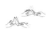
- Figure 1 is an explanatory diagram showing a flapping bird created with origami. As shown in Figure 1, when the neck and tail parts of the origami "flapping bird" are held with both hands and pulled towards each other, the left and right wings close as if flapping.
- the Gripping Device in Patent Document 1 is realized by making cuts in a sheet of flexible material, and by pulling two actuating tabs corresponding to the neck and tail parts, the upper and lower jaw parts corresponding to the left and right wings close, making it possible to grip an object.
- Patent Document 1 has a great concept of being made from a single sheet of flexible material, but it has some practical drawbacks due to its excessive focus on this concept.
- One of these, as can be seen from FIG. 6B in Patent Document 1, is that when the actuation tab is pulled, shear stress is concentrated in the notch, making it difficult to pull the actuation tab strongly.
- the disclosed technology aims to provide a practical gripping tool by improving the conventional gripping device to solve the above problems.
- the gripping device is a gripping device that grips an object based on the principle of driven kirigami, and is equipped with a sheet-like gripping part that covers the object, a tendon part that has a thread part inside and transmits the force that pulls the gripping part from both sides, a pulling part that is connected to the tendon part and functions as a pulley, and a fingertip part that is attached to and detached from the gripping part via a socket part, and the gripping part has a two-layer structure consisting of a coating layer and a core layer.
- the gripper according to the disclosed technology has the above configuration, so it can pull the actuation tab strongly and is more practical than conventional grippers.
- FIG. 1 is an explanatory diagram showing a flapping bird made from origami paper.
- FIG. 2 is an explanatory diagram showing the features of the gripping tool 100 according to the first embodiment.
- FIG. 3 is a cross-sectional view taken along line AA of FIG.
- FIG. 4 is an assembly diagram showing attachment and detachment of fingertip portion 150 in gripping tool 100 according to embodiment 1.
- FIG. 5 is an isometric view showing the appearance of the gripping tool 100 according to the first embodiment.
- FIG. 6 is an isometric view showing the appearance of the gripping device according to the first embodiment.
- FIG. 7 is an isometric view showing the appearance of a gripping device according to the second embodiment.
- FIG. 8 is an explanatory diagram showing the mechanism by which the pulling portion 130 is attached to and detached from the arm portion 200. As shown in FIG.
- Fig. 2 is an explanatory diagram showing the characteristics of the gripping tool 100 according to embodiment 1.
- the gripping tool 100 according to embodiment 1 includes a gripping portion 110, a tendon portion 120, a pulling portion 130, and a socket portion 140.
- the tendon portion 120 has a thread portion 122 therein.
- Fig. 3 is a cross-sectional view taken along line A-A in Fig. 2.
- the gripping part 110 constituting the gripping tool 100 preferably has a two-layer structure consisting of a coating layer 112 and a core layer 114.
- the core layer 114 may have a plurality of holes 116 formed therein in order to adjust the rigidity.
- FIG. 4 is an assembly diagram showing the attachment and detachment of the fingertip portion 150 in the gripping tool 100 according to the first embodiment.
- the fingertip portion 150 is detachable from the socket portion 140 that constitutes the gripping tool 100.
- Fig. 5 is an isometric view showing the appearance of gripping tool 100 according to embodiment 1.
- the two solid black arrows in Fig. 5 indicate the directions in which fingertip portion 150 moves as if the fingers are closing when gripping an object, and this is achieved by pulling two pulling portions 130 in the directions of the white arrows.
- This driving principle is the same as that of the origami "flapping bird" shown in Fig. 1. Origami flapping birds are not well known overseas. Another example of something based on the same principle is the mechanism in a pop-up picture book. Overseas, the mechanism in a pop-up picture book is sometimes called "kirigami.” Kirigami is also recognized overseas as a type of origami. Therefore, in this specification, this driving principle is referred to as the "principle of driven kirigami.”
- the gripping portion 110 constituting the gripping tool 100 is a sheet-like component that covers an object to be gripped.
- the gripping portion 110 is a component that corresponds to the palm and back of a human hand.
- the gripping part 110 constituting the gripping tool 100 preferably has a two-layer structure consisting of a coating layer 112 and a core layer 114.
- the coating layer 112 may be made of a synthetic resin such as silicone resin.
- the coating layer 112 may be made of a soft rubber-like material with high friction such as urethane rubber, in addition to silicone resin.
- the core layer 114 may be made of a synthetic resin such as PET (Polyethylene terephthalate).
- Such a two-layer structure gripping part 110 can be manufactured by a method of pouring resin into a mold.
- the core layer 114 may be made of a plastic material produced from plant-derived lactic acid such as PLA resin, in addition to PET.
- the core layer 114 is used to increase the rigidity that cannot be obtained by the coating layer 112 alone, so a material suitable for increasing the rigidity is selected.
- the gripping portion 110 as a whole needs to have the strength and properties to be able to elastically deform without breaking so that the principle of driving kirigami can be exerted.
- Tendon portion 120 constituting gripping tool 100 The tendon 120 constituting the gripping tool 100 is a component that transmits the force that pulls the gripping part 110 from both sides, and is a component that corresponds to a human tendon in a metaphorical sense.
- the gripping device having the gripping tool 100 according to the disclosed technology can be said to be a tendon-driven robot.
- the tendons 120 have a default V-shape as shown in FIG. 2, but when tension is applied the angle of the V becomes smaller.
- the tendon portion 120 has a structure including the thread portion 122 therein.
- the thread portion 122 may be, for example, a synthetic fiber such as a high-density polyethylene fiber or a chemical fiber.
- the thread portion 122 may be a nylon fishing line. Furthermore, the thread portion 122 may be a metal wire. The material of the tendon portion 120 that covers the thread portion 122 may be the same as that of the covering layer 112. The tendon portion 120 as a whole must have the strength and properties to allow the gripping portion 110 to be pulled from both sides without stretching or breaking.
- the tensioning portion 130 constituting the gripping tool 100 is a component corresponding to the Actuation Tab in Patent Document 1.
- the tensioning portion 130 constituting the gripping tool 100 is a component that connects the tendon portion 120 and the arm portion 200 described below. As shown in Figures 2 and 5, the tensioning portion 130 functions like a pulley and can pull the thread portion 122.
- the tensioning portion 130 is provided with an axial hole for attachment and detachment to the arm portion 200.
- the socket portion 140 constituting the gripping tool 100 is a component that connects the gripping portion 110 and the fingertip portion 150.
- the socket portion 140 enables the fingertip portion 150 to be attached to and detached from the gripping portion 110.
- Providing the socket portion 140 and making the fingertip portion 150 detachable allows a variety of fingertip portions 150 to be prepared in advance according to the anticipated grasping object, and during operation, a fingertip portion 150 with properties suitable for grasping the object can be selected.
- Providing the socket portion 140 and making the fingertip portion 150 detachable has the advantage of facilitating replacement for hygienic reasons and facilitating maintenance.
- Fingertip portion 150 constituting gripping tool 100 The fingertip parts 150 constituting the gripping tool 100 are parts that come into direct contact with the object to be gripped, and are metaphorically equivalent to human fingers. However, in Fig. 2 to Fig. 7 which explain the technology disclosed herein, the fingertip parts 150 are not depicted as being independently movable like human fingers.
- the fingertip portion 150 may be made of the same material as the gripping portion 110.
- the fingertip portion 150 may also have the same two-layer structure as the gripping portion 110.
- an advantageous effect of the gripping tool 100 according to the present disclosure is that the fingertip portion 150 is detachable, so that a material and structure suitable for gripping an object to be gripped can be adopted.
- the conventional Gripping Device shown in Patent Document 1 is limited to the concept of being manufactured from a single sheet of flexible material, and therefore has a practical disadvantage in that the rigidity of the portion corresponding to the fingertip is not necessarily sufficient.
- the feature of the present disclosure which includes the socket portion 140 and the fingertip portion 150, is an ingenuity for overcoming this practical disadvantage. It is important that the fingertip 150 has the rigidity and friction to prevent the object from slipping off when being grasped. It is also important that the fingertip 150 has flexibility so as not to damage the object when being grasped.
- fingertip 150 it is conceivable to prepare multiple types of fingertip 150 according to the intended objects to be grasped. This idea is the same as the fact that tweezers are prepared with various tip shapes according to the purpose of use. For example, if the object to be grasped is a plate-like object such as a board or a card, the fingertip 150 may have a thin tip and a shape that is slightly curved inward in the grasping direction. By designing the fingertip 150 in this way, it is possible to grasp and lift up a plate-like object placed on a table.
- FIG. 6 is an isometric view showing the appearance of the gripping device according to the first embodiment.
- the gripping device according to the first embodiment includes a gripping tool 100, an arm portion 200-A, and a drive portion 300.
- the arm 200 constituting the gripping device is a component that connects the gripping tool 100 and the drive unit 300.
- the arm 200 can be said to be a component that corresponds to a human arm, figuratively speaking.
- the reference symbol -A is added to the arm 200, and the arm 200-A is displayed.
- the arm portion 200-A has, for example, a shaft-like shape at its lower tip (hereinafter referred to as the “detachable shaft”), and can hold the gripping tool 100 by passing the detachable shaft through an axial hole provided in the tensioning portion 130. 6, when the pulling portion 130 of the arm 200-A is pulled in the direction indicated by the white arrow, the restoring force of the gripping portion 110 pulls the arm 200-A in the opposite direction to the white arrow. The gripping tool 100 is held by a force based on the restoring force of the gripping portion 110. If the arm 200-A is driven in the direction opposite to the white arrow to loosen the thread portion 122, the restoring force of the gripping portion 110 weakens. In other words, the gripping device according to the disclosed technology can easily remove the gripping tool 100 from the arm 200-A by driving the arm 200-A to loosen the tension on the thread portion 122.
- the detachable shaft a shaft-like shape at its lower tip
- Fig. 8 is an explanatory diagram showing the mechanism by which the tensioning part 130 is attached to and detached from the arm part 200.
- a detachment shaft is provided on the arm part 200, and a shaft hole is provided on the tensioning part 130.
- the diameter of the shaft hole is larger than the diameter of the detachment shaft.
- the arm portion 200 may be provided with a taper or step on the detachment shaft to prevent the detachment shaft from slipping out of the shaft hole when the object to be grasped is heavy.
- the driving unit 300 constituting the gripping device is a component that drives the arm unit 200.
- the driving unit 300 may be realized by an electric slider.
- the electric slider includes a motor and a mechanism that converts rotational motion into linear motion. Since it is sufficient for the driving unit 300 to realize linear motion, a linear motor may be adopted.
- the gripping device must be able to control not only the opening and closing of the gripping tool 100, but also the position and posture of the gripping tool 100 required to grip the object to be gripped.
- Figure 6 shows a drive unit 300 that realizes the opening and closing of the gripping tool 100, but does not show all of the components required for the gripping device.
- the gripping device has a mechanism and drive source that change the position and posture of the gripping tool 100.
- the advantageous effect of the gripper 100 according to the first embodiment is that the gripper 100 is equipped with a tendon portion 120 having a thread portion 122 therein and a pulling portion 130 that functions like a pulley, so that shear stress does not concentrate on the cut portion of the sheet, and the pulling portion 130, which is the operating tab, can be pulled strongly.
- Another advantageous effect of the gripping tool 100 according to embodiment 1 is that by making the fingertip portion 150 detachable, a material and structure suitable for gripping the object to be gripped can be adopted, and the rigidity of the fingertip portion 150 necessary for gripping can be ensured.
- the advantageous effect of the gripping device of embodiment 1 is that since the pulling portion 130 is provided with an axial hole for attachment and detachment to the arm portion 200-A, and the arm portion 200-A is provided with a detachment axis, by driving the arm portion 200-A to release the tension on the thread portion 122, the gripping tool 100 can be easily removed from the arm portion 200-A. Therefore, the gripping device according to the disclosed technique can provide a disposable gripping tool 100 together with the gripped object to be discarded, for example, at a site where contaminated medical waste or radioactive materials are handled, thereby contributing to automation.
- the gripping tool 100 and gripping device according to embodiment 1 are more practical than those according to the prior art.
- Embodiment 2 The gripping device according to the second embodiment is a modified example of the gripping device according to the disclosed technique. Unless otherwise specified, the same reference numerals as those used in the first embodiment are used in the second embodiment. Furthermore, in the second embodiment, descriptions that overlap with those in the first embodiment are omitted as appropriate.
- the reference numeral When emphasizing that the arm portion 200 is the aspect in the second embodiment, the reference numeral will be followed by -B, and the arm portion will be displayed as "arm portion 200-B.”
- FIG. 7 is an isometric view showing the appearance of a gripping device according to the second embodiment.
- arm 200-A moves in the horizontal direction indicated by the white arrow, thereby causing fingertip 150 to grip.
- arm 200-B moves in the vertical direction indicated by the white arrow, thereby causing fingertip 150 to grip.
- the drive direction of arm 200 is converted from the horizontal direction to the vertical direction by two guide rollers 210, as shown in Fig. 7.
- guide roller 210 When viewed from thread portion 122, guide roller 210 functions as a pulley, similar to tension portion 130.
- the advantage unique to the gripping device of embodiment 2 is that the driving direction of arm 200-B is changed to the vertical direction, making it possible to reduce the footprint of the device compared to embodiment 1.
- Another effect unique to the gripping device of embodiment 2 is that by providing two guide rollers 210, it is possible to prevent the gripping tool 100 from rotating around the axis on which it is pulled, which would be an unstable state.
- the gripping device according to embodiment 2 like the gripping device according to embodiment 1, is more practical than those according to the prior art.
- the gripping tool 100 and gripping device according to the disclosed technique can be applied to robotic automation in the medical and food fields, for example, and has industrial applicability.
- the gripping device according to the disclosed technique can provide a disposable gripping tool 100 at sites where contaminated medical waste or radioactive materials are handled, and can contribute to automation.
Landscapes
- Engineering & Computer Science (AREA)
- Robotics (AREA)
- Mechanical Engineering (AREA)
- Health & Medical Sciences (AREA)
- General Health & Medical Sciences (AREA)
- Orthopedic Medicine & Surgery (AREA)
- Rheumatology (AREA)
- Manipulator (AREA)
Priority Applications (7)
| Application Number | Priority Date | Filing Date | Title |
|---|---|---|---|
| PCT/JP2022/038496 WO2024084534A1 (ja) | 2022-10-17 | 2022-10-17 | 把持具及び把持装置 |
| CN202280100797.5A CN119998087A (zh) | 2022-10-17 | 2022-10-17 | 把持工具和把持装置 |
| JP2024546373A JP7573794B2 (ja) | 2022-10-17 | 2022-10-17 | 把持具及び把持装置 |
| DE112022007658.5T DE112022007658B4 (de) | 2022-10-17 | 2022-10-17 | Greifwerkzeug mit Kirigami-Antriebsprinzip und Greifeinrichtung |
| PCT/JP2023/013037 WO2024084723A1 (ja) | 2022-10-17 | 2023-03-30 | 把持具、把持装置、及びロボットハンド用のアタッチメント |
| JP2023536333A JP7466780B1 (ja) | 2022-10-17 | 2023-03-30 | 把持具、把持装置、及びロボットハンド用のアタッチメント |
| US19/079,005 US20250205909A1 (en) | 2022-10-17 | 2025-03-13 | Gripping tool and gripping device |
Applications Claiming Priority (1)
| Application Number | Priority Date | Filing Date | Title |
|---|---|---|---|
| PCT/JP2022/038496 WO2024084534A1 (ja) | 2022-10-17 | 2022-10-17 | 把持具及び把持装置 |
Related Child Applications (1)
| Application Number | Title | Priority Date | Filing Date |
|---|---|---|---|
| US19/079,005 Continuation US20250205909A1 (en) | 2022-10-17 | 2025-03-13 | Gripping tool and gripping device |
Publications (1)
| Publication Number | Publication Date |
|---|---|
| WO2024084534A1 true WO2024084534A1 (ja) | 2024-04-25 |
Family
ID=90737239
Family Applications (2)
| Application Number | Title | Priority Date | Filing Date |
|---|---|---|---|
| PCT/JP2022/038496 Ceased WO2024084534A1 (ja) | 2022-10-17 | 2022-10-17 | 把持具及び把持装置 |
| PCT/JP2023/013037 Ceased WO2024084723A1 (ja) | 2022-10-17 | 2023-03-30 | 把持具、把持装置、及びロボットハンド用のアタッチメント |
Family Applications After (1)
| Application Number | Title | Priority Date | Filing Date |
|---|---|---|---|
| PCT/JP2023/013037 Ceased WO2024084723A1 (ja) | 2022-10-17 | 2023-03-30 | 把持具、把持装置、及びロボットハンド用のアタッチメント |
Country Status (5)
| Country | Link |
|---|---|
| US (1) | US20250205909A1 (https=) |
| JP (1) | JP7573794B2 (https=) |
| CN (1) | CN119998087A (https=) |
| DE (1) | DE112022007658B4 (https=) |
| WO (2) | WO2024084534A1 (https=) |
Citations (7)
| Publication number | Priority date | Publication date | Assignee | Title |
|---|---|---|---|---|
| JPS5870892U (ja) * | 1981-11-06 | 1983-05-13 | クラリオン株式会社 | 産業用ロボツトにおける把持装置 |
| JPS61244480A (ja) * | 1985-04-22 | 1986-10-30 | オムロン株式会社 | ワ−クハンド装置 |
| JP2001219392A (ja) * | 2000-02-09 | 2001-08-14 | Kawasaki Heavy Ind Ltd | 把持装置 |
| US20100215473A1 (en) * | 2007-08-28 | 2010-08-26 | Scanvaegt International A/S | Gripping device, for example for a robot |
| JP2011189415A (ja) * | 2010-03-12 | 2011-09-29 | Ihi Corp | ロボットハンドとその爪部材交換方法 |
| JP2018079550A (ja) * | 2016-11-18 | 2018-05-24 | 住友重機械工業株式会社 | 把持装置および把持方法 |
| WO2020237058A1 (en) * | 2019-05-21 | 2020-11-26 | Trustees Of Boston University | Gripping devices and methods for making the same |
Family Cites Families (4)
| Publication number | Priority date | Publication date | Assignee | Title |
|---|---|---|---|---|
| US3610670A (en) | 1968-07-30 | 1971-10-05 | Karl M Keck | Holders for safety razor blade carriers or other objects |
| JP2000157088A (ja) * | 1998-11-25 | 2000-06-13 | Index Japan:Kk | 汚物処理袋 |
| JP2000263487A (ja) | 1999-03-17 | 2000-09-26 | Ngk Insulators Ltd | 外周ならい式チャック装置 |
| EP3035873A4 (en) | 2013-08-20 | 2017-04-26 | Brigham Young University | Surgical forceps |
-
2022
- 2022-10-17 WO PCT/JP2022/038496 patent/WO2024084534A1/ja not_active Ceased
- 2022-10-17 DE DE112022007658.5T patent/DE112022007658B4/de active Active
- 2022-10-17 CN CN202280100797.5A patent/CN119998087A/zh active Pending
- 2022-10-17 JP JP2024546373A patent/JP7573794B2/ja active Active
-
2023
- 2023-03-30 WO PCT/JP2023/013037 patent/WO2024084723A1/ja not_active Ceased
-
2025
- 2025-03-13 US US19/079,005 patent/US20250205909A1/en active Pending
Patent Citations (7)
| Publication number | Priority date | Publication date | Assignee | Title |
|---|---|---|---|---|
| JPS5870892U (ja) * | 1981-11-06 | 1983-05-13 | クラリオン株式会社 | 産業用ロボツトにおける把持装置 |
| JPS61244480A (ja) * | 1985-04-22 | 1986-10-30 | オムロン株式会社 | ワ−クハンド装置 |
| JP2001219392A (ja) * | 2000-02-09 | 2001-08-14 | Kawasaki Heavy Ind Ltd | 把持装置 |
| US20100215473A1 (en) * | 2007-08-28 | 2010-08-26 | Scanvaegt International A/S | Gripping device, for example for a robot |
| JP2011189415A (ja) * | 2010-03-12 | 2011-09-29 | Ihi Corp | ロボットハンドとその爪部材交換方法 |
| JP2018079550A (ja) * | 2016-11-18 | 2018-05-24 | 住友重機械工業株式会社 | 把持装置および把持方法 |
| WO2020237058A1 (en) * | 2019-05-21 | 2020-11-26 | Trustees Of Boston University | Gripping devices and methods for making the same |
Also Published As
| Publication number | Publication date |
|---|---|
| WO2024084723A1 (ja) | 2024-04-25 |
| JP7573794B2 (ja) | 2024-10-25 |
| CN119998087A (zh) | 2025-05-13 |
| US20250205909A1 (en) | 2025-06-26 |
| JPWO2024084534A1 (https=) | 2024-04-25 |
| DE112022007658B4 (de) | 2026-03-05 |
| DE112022007658T5 (de) | 2025-06-12 |
Similar Documents
| Publication | Publication Date | Title |
|---|---|---|
| US7950710B2 (en) | Robot | |
| JP4962728B2 (ja) | ロボット | |
| JP6811267B2 (ja) | 柔軟劣駆動把持具 | |
| JP6691583B2 (ja) | 指が改良されたヒューマノイドロボットに設けることが意図された手 | |
| DE102020207037B4 (de) | Greifer | |
| JP5015224B2 (ja) | 双方向腱ターミネーター | |
| CN109278034A (zh) | 一种绳索驱动柔性手爪及机器人 | |
| KR102010550B1 (ko) | 가변 강성 그리퍼 시스템 | |
| WO2018180782A1 (ja) | 指機構およびこの指機構を組み込んだ人間型ハンド | |
| JP2009166181A (ja) | ロボットハンド | |
| JP7573794B2 (ja) | 把持具及び把持装置 | |
| CN110730707A (zh) | 具有合成纤维胶的机器人和抓取器 | |
| KR101846083B1 (ko) | 로봇 핸드 | |
| JP7466780B1 (ja) | 把持具、把持装置、及びロボットハンド用のアタッチメント | |
| EP3715068B1 (en) | End effector device and robotic device | |
| CN112809727B (zh) | 一种绳牵引刚柔耦合变刚度夹持器 | |
| JP7201377B2 (ja) | エンドエフェクタおよびそれを備えるロボット | |
| CN120395941B (zh) | 灵巧手手指、灵巧手和机器人 | |
| CN117897262A (zh) | 机器人手 | |
| KR101559695B1 (ko) | 로봇 손가락 기구 | |
| Nomura et al. | Development of multi joint gripper and its dexterous grasping | |
| CN224043797U (zh) | 灵巧手、机械臂末端执行器和机器人 | |
| CN220660890U (zh) | 一种仿生机械手 | |
| JP7341505B2 (ja) | ロボットハンド | |
| CN212399622U (zh) | 一种机械抓手 |
Legal Events
| Date | Code | Title | Description |
|---|---|---|---|
| 121 | Ep: the epo has been informed by wipo that ep was designated in this application |
Ref document number: 22962646 Country of ref document: EP Kind code of ref document: A1 |
|
| ENP | Entry into the national phase |
Ref document number: 2024546373 Country of ref document: JP Kind code of ref document: A |
|
| WWE | Wipo information: entry into national phase |
Ref document number: 202280100797.5 Country of ref document: CN |
|
| WWE | Wipo information: entry into national phase |
Ref document number: 112022007658 Country of ref document: DE |
|
| WWP | Wipo information: published in national office |
Ref document number: 202280100797.5 Country of ref document: CN |
|
| WWP | Wipo information: published in national office |
Ref document number: 112022007658 Country of ref document: DE |
|
| 122 | Ep: pct application non-entry in european phase |
Ref document number: 22962646 Country of ref document: EP Kind code of ref document: A1 |
|
| WWG | Wipo information: grant in national office |
Ref document number: 112022007658 Country of ref document: DE |