WO2024079986A1 - 画像復号装置、画像復号方法及びプログラム - Google Patents
画像復号装置、画像復号方法及びプログラム Download PDFInfo
- Publication number
- WO2024079986A1 WO2024079986A1 PCT/JP2023/029766 JP2023029766W WO2024079986A1 WO 2024079986 A1 WO2024079986 A1 WO 2024079986A1 JP 2023029766 W JP2023029766 W JP 2023029766W WO 2024079986 A1 WO2024079986 A1 WO 2024079986A1
- Authority
- WO
- WIPO (PCT)
- Prior art keywords
- decoded
- synthesis unit
- image decoding
- intra prediction
- decoding device
- Prior art date
- Legal status (The legal status is an assumption and is not a legal conclusion. Google has not performed a legal analysis and makes no representation as to the accuracy of the status listed.)
- Ceased
Links
Images








Classifications
-
- H—ELECTRICITY
- H04—ELECTRIC COMMUNICATION TECHNIQUE
- H04N—PICTORIAL COMMUNICATION, e.g. TELEVISION
- H04N19/00—Methods or arrangements for coding, decoding, compressing or decompressing digital video signals
- H04N19/10—Methods or arrangements for coding, decoding, compressing or decompressing digital video signals using adaptive coding
- H04N19/169—Methods or arrangements for coding, decoding, compressing or decompressing digital video signals using adaptive coding characterised by the coding unit, i.e. the structural portion or semantic portion of the video signal being the object or the subject of the adaptive coding
- H04N19/18—Methods or arrangements for coding, decoding, compressing or decompressing digital video signals using adaptive coding characterised by the coding unit, i.e. the structural portion or semantic portion of the video signal being the object or the subject of the adaptive coding the unit being a set of transform coefficients
-
- H—ELECTRICITY
- H04—ELECTRIC COMMUNICATION TECHNIQUE
- H04N—PICTORIAL COMMUNICATION, e.g. TELEVISION
- H04N19/00—Methods or arrangements for coding, decoding, compressing or decompressing digital video signals
- H04N19/10—Methods or arrangements for coding, decoding, compressing or decompressing digital video signals using adaptive coding
- H04N19/102—Methods or arrangements for coding, decoding, compressing or decompressing digital video signals using adaptive coding characterised by the element, parameter or selection affected or controlled by the adaptive coding
- H04N19/103—Selection of coding mode or of prediction mode
- H04N19/105—Selection of the reference unit for prediction within a chosen coding or prediction mode, e.g. adaptive choice of position and number of pixels used for prediction
-
- H—ELECTRICITY
- H04—ELECTRIC COMMUNICATION TECHNIQUE
- H04N—PICTORIAL COMMUNICATION, e.g. TELEVISION
- H04N19/00—Methods or arrangements for coding, decoding, compressing or decompressing digital video signals
- H04N19/10—Methods or arrangements for coding, decoding, compressing or decompressing digital video signals using adaptive coding
- H04N19/102—Methods or arrangements for coding, decoding, compressing or decompressing digital video signals using adaptive coding characterised by the element, parameter or selection affected or controlled by the adaptive coding
- H04N19/103—Selection of coding mode or of prediction mode
- H04N19/11—Selection of coding mode or of prediction mode among a plurality of spatial predictive coding modes
-
- H—ELECTRICITY
- H04—ELECTRIC COMMUNICATION TECHNIQUE
- H04N—PICTORIAL COMMUNICATION, e.g. TELEVISION
- H04N19/00—Methods or arrangements for coding, decoding, compressing or decompressing digital video signals
- H04N19/10—Methods or arrangements for coding, decoding, compressing or decompressing digital video signals using adaptive coding
- H04N19/102—Methods or arrangements for coding, decoding, compressing or decompressing digital video signals using adaptive coding characterised by the element, parameter or selection affected or controlled by the adaptive coding
- H04N19/119—Adaptive subdivision aspects, e.g. subdivision of a picture into rectangular or non-rectangular coding blocks
-
- H—ELECTRICITY
- H04—ELECTRIC COMMUNICATION TECHNIQUE
- H04N—PICTORIAL COMMUNICATION, e.g. TELEVISION
- H04N19/00—Methods or arrangements for coding, decoding, compressing or decompressing digital video signals
- H04N19/10—Methods or arrangements for coding, decoding, compressing or decompressing digital video signals using adaptive coding
- H04N19/102—Methods or arrangements for coding, decoding, compressing or decompressing digital video signals using adaptive coding characterised by the element, parameter or selection affected or controlled by the adaptive coding
- H04N19/124—Quantisation
-
- H—ELECTRICITY
- H04—ELECTRIC COMMUNICATION TECHNIQUE
- H04N—PICTORIAL COMMUNICATION, e.g. TELEVISION
- H04N19/00—Methods or arrangements for coding, decoding, compressing or decompressing digital video signals
- H04N19/10—Methods or arrangements for coding, decoding, compressing or decompressing digital video signals using adaptive coding
- H04N19/134—Methods or arrangements for coding, decoding, compressing or decompressing digital video signals using adaptive coding characterised by the element, parameter or criterion affecting or controlling the adaptive coding
- H04N19/136—Incoming video signal characteristics or properties
- H04N19/14—Coding unit complexity, e.g. amount of activity or edge presence estimation
-
- H—ELECTRICITY
- H04—ELECTRIC COMMUNICATION TECHNIQUE
- H04N—PICTORIAL COMMUNICATION, e.g. TELEVISION
- H04N19/00—Methods or arrangements for coding, decoding, compressing or decompressing digital video signals
- H04N19/10—Methods or arrangements for coding, decoding, compressing or decompressing digital video signals using adaptive coding
- H04N19/169—Methods or arrangements for coding, decoding, compressing or decompressing digital video signals using adaptive coding characterised by the coding unit, i.e. the structural portion or semantic portion of the video signal being the object or the subject of the adaptive coding
- H04N19/17—Methods or arrangements for coding, decoding, compressing or decompressing digital video signals using adaptive coding characterised by the coding unit, i.e. the structural portion or semantic portion of the video signal being the object or the subject of the adaptive coding the unit being an image region, e.g. an object
- H04N19/176—Methods or arrangements for coding, decoding, compressing or decompressing digital video signals using adaptive coding characterised by the coding unit, i.e. the structural portion or semantic portion of the video signal being the object or the subject of the adaptive coding the unit being an image region, e.g. an object the region being a block, e.g. a macroblock
-
- H—ELECTRICITY
- H04—ELECTRIC COMMUNICATION TECHNIQUE
- H04N—PICTORIAL COMMUNICATION, e.g. TELEVISION
- H04N19/00—Methods or arrangements for coding, decoding, compressing or decompressing digital video signals
- H04N19/10—Methods or arrangements for coding, decoding, compressing or decompressing digital video signals using adaptive coding
- H04N19/169—Methods or arrangements for coding, decoding, compressing or decompressing digital video signals using adaptive coding characterised by the coding unit, i.e. the structural portion or semantic portion of the video signal being the object or the subject of the adaptive coding
- H04N19/182—Methods or arrangements for coding, decoding, compressing or decompressing digital video signals using adaptive coding characterised by the coding unit, i.e. the structural portion or semantic portion of the video signal being the object or the subject of the adaptive coding the unit being a pixel
-
- H—ELECTRICITY
- H04—ELECTRIC COMMUNICATION TECHNIQUE
- H04N—PICTORIAL COMMUNICATION, e.g. TELEVISION
- H04N19/00—Methods or arrangements for coding, decoding, compressing or decompressing digital video signals
- H04N19/44—Decoders specially adapted therefor, e.g. video decoders which are asymmetric with respect to the encoder
-
- H—ELECTRICITY
- H04—ELECTRIC COMMUNICATION TECHNIQUE
- H04N—PICTORIAL COMMUNICATION, e.g. TELEVISION
- H04N19/00—Methods or arrangements for coding, decoding, compressing or decompressing digital video signals
- H04N19/50—Methods or arrangements for coding, decoding, compressing or decompressing digital video signals using predictive coding
- H04N19/593—Methods or arrangements for coding, decoding, compressing or decompressing digital video signals using predictive coding involving spatial prediction techniques
-
- H—ELECTRICITY
- H04—ELECTRIC COMMUNICATION TECHNIQUE
- H04N—PICTORIAL COMMUNICATION, e.g. TELEVISION
- H04N19/00—Methods or arrangements for coding, decoding, compressing or decompressing digital video signals
- H04N19/60—Methods or arrangements for coding, decoding, compressing or decompressing digital video signals using transform coding
- H04N19/61—Methods or arrangements for coding, decoding, compressing or decompressing digital video signals using transform coding in combination with predictive coding
- H04N19/619—Methods or arrangements for coding, decoding, compressing or decompressing digital video signals using transform coding in combination with predictive coding the transform being operated outside the prediction loop
-
- H—ELECTRICITY
- H04—ELECTRIC COMMUNICATION TECHNIQUE
- H04N—PICTORIAL COMMUNICATION, e.g. TELEVISION
- H04N19/00—Methods or arrangements for coding, decoding, compressing or decompressing digital video signals
- H04N19/70—Methods or arrangements for coding, decoding, compressing or decompressing digital video signals characterised by syntax aspects related to video coding, e.g. related to compression standards
Definitions
- the present invention relates to an image decoding device, an image decoding method, and a program.
- Non-Patent Documents 1 to 3 disclose the geometric partitioning mode (GPM). GPM divides a rectangular block into two along a diagonal dividing line, and performs motion compensation (inter prediction) or intra prediction for each of the two divided small regions.
- GPM geometric partitioning mode
- motion compensation (inter prediction) pixels and intra prediction pixels are generated for each divided small region using a motion vector or intra prediction mode, and then these two prediction pixels are combined using a weighted average according to the distance from the dividing line.
- the method of dividing rectangular blocks using the geometric division mode in Non-Patent Document 1 and Non-Patent Document 2 is defined by a single straight line, and 64 types of division methods are preset with combinations of different angles and positions.
- the block to be decoded contains a boundary between the foreground and background, it can be separated into two small regions if the boundary is a straight line, and highly efficient coding can be achieved by using a prediction method appropriate for each.
- the present invention has been made in consideration of the above-mentioned problem, and aims to provide an image decoding device, an image decoding method, and a program with high encoding efficiency.
- the first feature of the present invention is an image decoding device comprising: a decoding unit that decodes control information and a quantized value; an inverse quantization unit that inversely quantizes the quantized value to obtain a transform coefficient; an inverse transform unit that inversely transforms the transform coefficient to obtain a prediction residual; an intra prediction unit that generates a first predicted pixel based on decoded pixels and the control information; an accumulation unit that accumulates the decoded pixels; a motion compensation unit that generates a second predicted pixel based on the accumulated decoded pixels and the control information; a synthesis unit that synthesizes any combination including at least one of the first predicted pixel and the second predicted pixel into small regions divided by a plurality of line segments based on the control information to obtain a third predicted pixel; and an adder that adds any one of the first predicted pixel, the second predicted pixel, and the third predicted pixel to the prediction residual to obtain the decoded pixel.
- the second feature of the present invention is an image decoding method comprising the steps of: decoding control information and a quantized value; inversely quantizing the quantized value to obtain a transform coefficient; inversely transforming the transform coefficient to obtain a prediction residual; generating a first predicted pixel based on decoded pixels and the control information; accumulating the decoded pixels; generating a second predicted pixel based on the accumulated decoded pixels and the control information; synthesizing an arbitrary combination including at least one of the first predicted pixel and the second predicted pixel into small regions divided by a plurality of line segments based on the control information to obtain a third predicted pixel; and obtaining the decoded pixel by adding any one of the first predicted pixel, the second predicted pixel, and the third predicted pixel to the prediction residual.
- the third feature of the present invention is a program for making a computer function as an image decoding device, the image decoding device comprising: a decoding unit that decodes control information and a quantized value; an inverse quantization unit that inversely quantizes the quantized value to obtain a transform coefficient; an inverse transform unit that inversely transforms the transform coefficient to obtain a prediction residual; an intra prediction unit that generates a first predicted pixel based on decoded pixels and the control information; a storage unit that stores the decoded pixels; a motion compensation unit that generates a second predicted pixel based on the stored decoded pixels and the control information; a synthesis unit that synthesizes any combination including at least one of the first predicted pixel and the second predicted pixel into small regions divided by a plurality of line segments based on the control information to obtain a third predicted pixel; and an adder that adds any one of the first predicted pixel, the second predicted pixel, and the third predicted pixel to the prediction residual to obtain the decoded
- the present invention provides an image decoding device, an image decoding method, and a program with high coding efficiency.
- FIG. 1 is a diagram showing an example of functional blocks of an image decoding device 200 according to an embodiment.
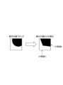
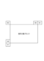
- FIG. 2 is a diagram showing an example of a case where the geometric partitioning mode (GPM) is used for partitioning into small regions.
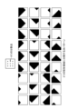
- FIG. 5 is a diagram showing examples of selectable division shapes of a block to be decoded.
- FIG. 6 is a diagram showing examples of selectable division shapes of a block to be decoded.
- FIG. 1 is a diagram showing an example of functional blocks of an image decoding device 200 according to an embodiment.
- FIG. 2 is a diagram showing an example of a case where the geometric partitioning mode (GPM) is used for partitioning into small regions.
- FIG. 3 is a diagram showing an
- FIG. 7 is a diagram showing an example of three patterns of weighting coefficients assigned to the division boundaries of the small region B shown in FIG.
- Figure 8 shows an example of a case in which a partition boundary is formed by two partition lines in the vertical and horizontal directions for a block to be decoded, and synthetic prediction is performed on a predicted pixel basis according to the distance from these two partition lines (partition line 1 and partition line 2).
- FIG. 9 is a diagram for explaining an example of a blending region for the division lines 1 and 2.
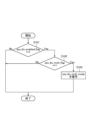
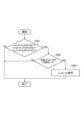
- FIG. 10 is a flowchart showing an example of an operation for setting a selection method for a multiple line segment division mode on a sequence basis.
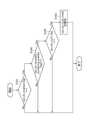
- FIG. 11 is a flowchart showing an example of an operation for setting a selection method for the multiple line segment division mode in block units.
- FIG. 12 is a diagram showing an example of a case in which an angle prediction mode parallel to the dividing line 1 is applied.
- FIG. 13 is a diagram illustrating the intra prediction mode derivation method according to the present embodiment.
- FIG. 14 is a diagram illustrating the intra prediction mode derivation method according to the present embodiment.
- FIG. 15 is a diagram illustrating the intra prediction mode derivation method according to the present embodiment.
- FIG. 16 is a diagram illustrating the intra prediction mode derivation method according to the present embodiment.
- FIG. 17 is a diagram showing an example of a method for deriving an intra prediction mode based on adjacent reference blocks for normal intra prediction according to Non-Patent Document 1 and Non-Patent Document 2, and a method for deriving an intra prediction mode based on adjacent reference blocks for a geometric partitioning mode according to this embodiment to which the above derivation method is applied.
- FIG. 18 is a diagram showing an example of the association between cu_div_idx, divDirectionIdx, and divLocationIdx.
- FIG. 19 is a flowchart showing a modified example of the operation for setting the multiple line segment division mode selection method on a sequence basis.
- FIG. 20 is a flowchart showing a modified example of the operation for setting a selection method for a division mode including a multiple line segment division mode in block units.
- Figure 1 is a diagram showing an example of functional blocks of the image decoding device 200 according to this embodiment.
- the image decoding device 200 has a code input unit 210, a decoding unit 201, an inverse quantization unit 202, an inverse transform unit 203, an intra prediction unit 204, a synthesis unit 205, an adder 206, an accumulation unit 207, a motion compensation unit 208, and an image output unit 220.
- the code input unit 210 is configured to obtain code information encoded by the image encoding device.
- the decoding unit 201 is configured to decode the control information and the quantization value from the code information input from the code input unit 210.
- the decoding unit 201 is configured to output the control information and the quantization value by performing variable length decoding on the code information.
- the quantized value is sent to the inverse quantization unit 202, and the control information is sent to the intra prediction unit 204, the synthesis unit 205, and the motion compensation unit 208.
- control information includes information necessary for controlling the intra prediction unit 204, the synthesis unit 205, the motion compensation unit 208, etc., and may include header information such as a sequence parameter set, a picture parameter set, a picture header, a slice header, etc.
- the inverse quantization unit 202 is configured to inverse quantize the quantized values sent from the decoding unit 201 to generate decoded transform coefficients. These transform coefficients are sent to the inverse transform unit 203.
- the inverse transform unit 203 is configured to inversely transform the transform coefficients sent from the inverse quantization unit 202 to generate decoded prediction residuals. These prediction residuals are sent to the adder 206.
- the intra prediction unit 204 is configured to generate a first predicted pixel based on the decoded pixel and the control information sent from the decoding unit 201.
- the decoded pixel is obtained via the adder 206 and stored in the storage unit 207.
- the first predicted pixel is sent to the adder 206.
- the storage unit 207 is configured to cumulatively store the decoded pixels sent from the adder 206. These decoded pixels are referenced by the motion compensation unit 208 via the storage unit 207.
- the motion compensation unit 208 is configured to generate a second predicted pixel to be added to the prediction residual by the adder 206, based on the decoded pixels obtained by referring to the storage unit 207 and the control information decoded by the decoding unit 201.
- the generated second predicted pixel is sent to the adder 206 or the synthesis unit 205.
- the adder 206 is configured to add one of the first to third predicted pixels generated from the decoded pixels etc. to the prediction residual sent from the inverse transform unit 203 to obtain a decoded pixel. Such a decoded pixel is sent to the image output unit 220, the storage unit 207 and the intra prediction unit 204.
- the synthesis unit 205 is configured to synthesize any combination including at least one of the first and second predicted pixels described above into small regions divided by a plurality of line segments based on the control information decoded by the decoding unit 201 to generate a third predicted pixel.
- the following describes the synthesis unit 205, which is a characteristic component of the image decoding device 200 according to this embodiment.
- the role of the synthesis unit 205 is to divide the block to be decoded into multiple small regions (small region division) so that the prediction residual can be expressed with a small amount of code when the decoded pixels are calculated by the subsequent addition unit 206, and to predict the pixels of the block to be decoded with high accuracy by synthesizing the corresponding first predicted pixel or second predicted pixel (synthetic prediction).
- Figure 2 shows an example of a case where the geometric partitioning mode (GPM) is used for subregion partitioning.
- the block to be decoded is partitioned into subregions A and B by a single diagonal line.
- the division is limited to a single straight line, so it cannot handle cases where the boundary between the foreground and background is complex, and there is a problem that the coding efficiency cannot be sufficiently improved.
- the synthesis unit 205 divides the current block to be decoded by N line segments (N is a natural number greater than 1).
- the synthesis unit 205 may determine the division type of the multiple line segment division mode from the control information. Details will be described later.
- Increasing the number of lines N in the multiple line segment division mode has the effect of improving prediction accuracy, while decreasing the number of lines N in the multiple line segment division mode has the effect of reducing the amount of code required for the control information that represents the division shape.
- the synthesis unit 205 may set such a fixed value to a common value regardless of the length of the short side, the length of the long side, the size (area), or the aspect ratio of the block to be decoded.
- the synthesis unit 205 may set such fixed values to different values based on the length of the short side, the length of the long side, the size (area) or the aspect ratio of the block to be decoded.
- the synthesis unit 205 may also variably set the number N of line segments in the multiple line segment division mode. For example, when the synthesis unit 205 variably sets the number N of line segments in the multiple line segment division mode, the synthesis unit 205 may determine the number N of line segments in proportion to the length of the short side, the length of the long side, and the size (area) of the block to be decoded.
- the synthesis unit 205 may also limit at least one of the positional relationship and angle of the multiple line segments in order to reduce the amount of code in the control information that represents the division shape.
- the synthesis unit 205 may limit the first line segment to only the horizontal direction (0 degrees) or vertical direction (90 degrees) of the block to be decoded. Furthermore, the synthesis unit 205 may limit the n+1th line segment to only the vertical direction (90 degrees) with respect to the nth line segment.
- Non-Patent Document 1 because a partition shape in which the block to be decoded is divided into four equal parts in a square shape can be realized by the recursive rectangular block partitioning (quadtree, binary tree, and ternary tree partitioning) disclosed in Non-Patent Document 1, it is desirable to limit the composition unit 205 so that it cannot select arrangements that can be realized by such existing block partitioning.
- applying such a limitation corresponds to selecting the division shape (multiple line segments) of the block to be decoded from the pattern shown in FIG. 5 and the diagonal division pattern shown in FIG. 6 when the first line segment can be diagonal (45 degrees) in addition to horizontal (0 degrees) and vertical (90 degrees).
- the prediction accuracy can be improved, and by increasing the above-mentioned limitations, the amount of code for the control information expressing the division shape can be reduced.
- the synthesis unit 205 can set the above-mentioned limitation method either fixedly or variably.
- the synthesis unit 205 can also set different limitations depending on the size of the block to be decoded (length of the short side, length of the long side, size (area), aspect ratio, etc.).
- the number of division points is proportional to the length of the sides of the block to be decoded.
- the synthesis unit 205 can set a fixed number of division points, regardless of the size of the block to be decoded.
- the division points may be placed every L/(K+1) pixels, which is the ratio of the length L (L is a natural number) of the side of the block to be decoded to the number of pixels.
- L may be a natural number that is a power of 2 greater than or equal to 4, such as 4, 8, 16, 32, 64, or 128, as described in Non-Patent Document 1.
- K may be a natural number that is a power of 2 greater than or equal to 4, such as 4, 8, 16, 32, 64, or 128.
- K may be restricted so that L/(K+1) pixels is a natural number that is a power of 2 greater than or equal to 4, such as 4, 8, 16, 32, 64, or 128.
- the synthesis unit 205 may set K different division points for the vertical and horizontal sides (length and width) of the block to be decoded.
- the synthesis unit 205 may also include the center of the block to be decoded in FIG. 5 as a division point.
- Increasing the number of division points has the effect of improving prediction accuracy, while decreasing the number of division points has the effect of reducing the amount of code required to express the division shape.
- the synthesis unit 205 is configured to perform a weighted average (i.e., synthesis prediction) of the predicted pixels for each of the small areas A and B of the block to be decoded, which has been divided into multiple line segments, according to the distance of the dividing lines.
- a weighted average i.e., synthesis prediction
- the types of predicted pixels for such small regions A and B may be a combination of different inter-predicted pixels, such as the geometric partitioning mode disclosed in Non-Patent Document 1, a combination of inter-predicted pixels and intra-predicted pixels, such as the geometric partitioning mode intra-prediction disclosed in Non-Patent Document 2, or a combination of different intra-predicted pixels.
- different inter-predicted pixels are generated based on different motion vectors, and different intra-predicted pixels are generated in different intra-prediction modes.
- a weighted average according to the distance from the division line such as that used for synthesis prediction in the geometric division mode disclosed in Non-Patent Document 1 and Non-Patent Document 3, can be used.
- the sum of the weighting coefficients for multiple predicted pixels is designed to be 1 for each pixel, and the multiple predicted pixels are synthesized using such weighting coefficients by weighted averaging to obtain the predicted pixel by the synthesis unit 205.
- the input predicted pixel is used, and for pixels with a weighting factor of 0 (i.e., the minimum value), the input predicted pixel is not used.
- this is equivalent to dividing a unit block into multiple small regions, and determining which pixel of multiple input predicted pixels is to be applied where and in what proportion.
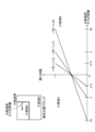
- Fig. 7 shows an example of three patterns of weighting coefficients to be assigned to the division boundary of the small area B shown in Fig. 2.
- the horizontal axis represents the distance in pixels from the position of the division boundary (division line), and the vertical axis represents the weighting coefficient.
- pattern (1) in which a weighting factor [0, 1] is assigned to the range [a, b] for distances a and b of predicted pixel units from a preset division boundary position; pattern (2) in which distances a and b are similarly doubled and a weighting factor [0, 1] is assigned to the range [2a, 2b]; and pattern (3) in which distances a and b are similarly halved and a weighting factor [0, 1] is assigned to the range [a/2, b/2].
- weighting coefficients are defined as xc, yc that are uniquely determined by the distance d(xc, yc) from the division boundary (division line), this is equivalent to providing multiple patterns (variable values) rather than a limited pattern (fixed values) for the width of the division boundary of the small region disclosed in Non-Patent Document 3, i.e., the width ⁇ where the weighting coefficient is other than the minimum or maximum value.
- xc, yc are coordinates within the block to be decoded.
- the synthesis unit 205 may be configured to set multiple weighting coefficients according to the inter-pixel distance from the division boundary.
- the synthesis unit 205 may be configured to set the weighting factor as described above as a weighting factor that is symmetrical with respect to the division boundary. With this configuration, b becomes unnecessary, and the amount of code can be reduced.
- a weighting coefficient may be set that is asymmetric with respect to the division boundary, with a ⁇ b.
- the synthesis unit 205 may be configured to set a weighting coefficient that is asymmetric with respect to the division boundary as the weighting coefficient described above. With this configuration, when there are different degrees of blur on both sides of the boundary, prediction can be made with high accuracy.
- the weighting coefficients can be set for multiple line segments by increasing the number of a and b instead of limiting them to two.
- the synthesis unit 205 can be configured to set weighting coefficients for multiple line segments according to the inter-pixel distance from the division boundary. With this configuration, it is possible to make highly accurate predictions when blurring occurs nonlinearly.
- the synthesis unit 205 can arbitrarily set the type, shape, and number of the above-mentioned patterns.
- the weighting coefficient was set to a value between 0 and 8, but it can also be set to other values such as 0 to 16 or 0 to 32.
- the maximum weighting coefficient can be increased to improve the accuracy of the weighted average on a pixel-by-pixel basis.
- the synthesis unit 205 may select from among pre-prepared combinations the settings of multiple weighting factors (width of the blending area, maximum and minimum values of the weighting factors) for small area A and small area B based on the control information sent from the decoding unit 201.
- the synthesis unit 205 may use such control information to select the above-mentioned weighting coefficient from multiple patterns prepared in advance (in Non-Patent Document 3, five patterns are 1/4 width, 1/2 width, 1 width, 2 times width, and 4 times width).
- the synthesis unit 205 may use the control information to reduce selectable candidates from multiple patterns of candidates prepared in advance according to the size, short side length, long side length, or aspect ratio of the block to be decoded, and then select the blending width indicated by the control information.
- the multiple line segment division mode unlike the synthesis prediction for the geometric division mode disclosed in Non-Patent Documents 1 to 3, there are multiple division boundaries (division lines) that divide the small regions, so synthesis prediction is performed for those multiple division lines.
- FIG. 8 shows an example of a case in which the partition boundary is formed by two partition lines in the vertical and horizontal directions for the block to be decoded, as shown in FIG. 5, and synthetic prediction is performed in units of predicted pixels according to the distance from the two partition lines (partition line 1 and partition line 2).
- the synthesis unit 205 may apply a common weighted average to the synthesis predictions for these multiple division lines.
- the synthesis unit 205 may apply a weighted average consisting of the maximum values of the different weighting coefficients and the distance from the dividing line as described above.
- the synthesis unit 205 may be configured to select a weighting factor from among a plurality of weighting factors depending on at least one of the length of the short side, the length of the long side, the aspect ratio, the size (number of pixels), or the type of division mode of the block to be decoded.
- the synthesis unit 205 may be configured to select a weighting factor from among multiple weighting factors depending on the type of intra prediction mode.
- the synthesis unit 205 may be configured to select a weighting factor from among multiple weighting factors according to the size (number of pixels) of the small area A or small area B divided within the block to be decoded using the multiple line segment division mode.
- the synthesis unit 205 may be configured to select a weighting factor from among multiple weighting factors depending on the size (number of pixels) of the division line.
- the synthesis unit 205 may be configured to select a weighting factor from among a plurality of weighting factors according to the ratio to the side of the block to be decoded that is in the same direction.
- Figure 9 is a diagram to explain an example of a blending area (gray area in Figure 9(a)) for division line 1 and division line 2.
- the overlapping blending area As shown in FIG. 9(a), the area where the blending areas for division line 1 and division line 2 overlap (hereinafter, the overlapping blending area) is indicated by a dashed frame.
- FIG. 9(b) shows an example of a weighting factor W_1A to be applied to the predicted pixels of small area A with respect to division line 1, and an example of a weighting factor W_2A to be applied to the predicted pixels of small area A with respect to division line 2.
- the weighting coefficients W_1B and W_2B for each small region B are calculated by subtracting W_1A and W_2A from the maximum weighting coefficients.
- the synthesis unit 205 may perform prediction synthesis of the third predicted pixel in the blending region and the overlap blending region using a newly generated weighting coefficient by selecting the minimum value of each element W_1A and W_2A of the weighting coefficient, as shown in calculation example 1 in FIG. 9(c).
- the synthesis unit 205 may perform prediction synthesis of the third predicted pixel of the blending region and the overlap blending region using a newly generated weighting coefficient by calculating the product of the elements W_1A and W_2A of the weighting coefficient, as shown in calculation example 2 of FIG. 9(c).
- the coding information input to the image decoding device 200 may include a sequence parameter set (SPS) that summarizes control information on a per-sequence basis.
- SPS sequence parameter set
- Such coding information may also include a picture parameter set (PPS) or a picture header (PH) that summarizes control information on a per-picture basis.
- PPS picture parameter set
- PH picture header
- such coding information may also include a slice header (SH) that summarizes control information on a per-slice basis.
- step S101 the decoding unit 201 determines whether sps_div_enabled_flag is 1 in the sequence parameter set.
- sps_div_enabled_flag is syntax that controls whether or not split mode is enabled. When sps_div_enabled_flag is 1, it indicates that split mode is enabled, and when sps_div_enabled_flag is 0, it indicates that split mode is disabled.
- step S102 If sps_div_enabled_flag is 1, this operation proceeds to step S102; if sps_div_enabled_flag is 0, this operation ends.
- step S102 the decoding unit 201 decodes sps_div_multi_flag.
- step S103 If sps_div_multi_flag is 1, this operation proceeds to step S103; if sps_div_multi_flag is 0, this operation ends.
- step S103 the decoding unit 201 decodes sps_div_multi_mode.
- sps_div_multi_mode is a syntax that controls the multiple line segment division mode.
- sps_div_multi_mode you can change the multiple line segment division mode setting according to the image characteristics on a sequence-by-sequence basis, which is expected to maximize coding efficiency.
- the decoding unit 201 When the border width candidate selection method is set on a picture-by-picture basis, the decoding unit 201 similarly decodes pps_div_enabled_flag, pps_div_multi_flag, and pps_div_multi_mode in the picture parameter set or picture header.
- pps_div_multi_mode you can change the multiple line segment division mode setting according to the image characteristics on a picture-by-picture basis, which is expected to maximize coding efficiency.
- the division types can be set to be limited to right angles, and for pictures made up of natural images, the division type restrictions can be relaxed, maximizing coding efficiency.
- the decoding unit 201 When the boundary width candidate selection method is set on a slice-by-slice basis, the decoding unit 201 similarly decodes sh_div_enabled_flag, sh_div_multi_flag, and sh_div_multi_mode in the slice header.
- sh_div_multi_mode you can change the multiple line segment division mode setting according to the image characteristics on a slice-by-slice basis, which is expected to maximize coding efficiency.
- the division types can be set to be limited to right angles, and for slice areas that contain natural images, the division type restrictions can be relaxed, maximizing coding efficiency.
- the decoding of the multiple line segment split mode itself can be omitted.
- the method of setting the multiple line segment division mode on a sequence basis, a picture basis, or a slice basis was described, but instead of setting these, the multiple line segment division mode may be set directly on a block basis, as described below.
- step S104 is included.
- step 104 the decoding unit 201 determines whether the technique for reordering the partition modes associated with the decoded value of cu_div_idx (control information) for identifying the partition mode based on template matching (described later) in the sequence parameter set is enabled based on whether sps_div_template_reordering_enabled_flag (control information), which controls the reordering on a sequence basis, is 1.
- sps_div_template_reordering_enabled_flag 1
- sps_div_template_reordering_enabled_flag 0
- sps_div_template_reordering_enabled_flag is decoded by the decoding unit 201 before step S104, or the value is estimated without being decoded.
- the decoding unit 201 estimates that the value of sps_div_template_reordering_enabled_flag is 0.
- step S102 If sps_div_template_reordering_enabled_flag is 1 (Yes), the decoding unit 201 proceeds to step S102. If sps_div_template_reordering_enabled_flag is 0 (No), the decoding unit 201 ends this process.
- template-based partition mode subscript sorting has the effect of shortening the code length of the partition mode subscript. Therefore, by determining that the multiple line partition mode is valid only when template-based partition mode subscript sorting is valid, the amount of code required for cu_div_idx, which is used to identify the type of multiple line partition mode or the type of partition mode including the multiple line partition mode on a target block basis, can be reduced, and as a result, improved coding performance can be expected.
- step S201 the decoding unit 201 determines whether any of sps_div_enabled_flag, pps_div_enabled_flag, and sh_div_enabled_flag is 1.
- step S202 If neither is 1, the operation ends; if either is 1, the operation proceeds to step S202.
- step S202 the decoding unit 201 determines whether the block to be decoded is in split mode.
- step S203 If the answer is Yes, the operation proceeds to step S203; if the answer is No, the operation ends.
- step S203 the decoding unit 201 decodes cu_div_idx, which is a control signal indicating the division mode.
- cu_div_idx is decoded to identify one of the candidate multiple line segment division modes selected by the lowest level div_multi_mode applied to the block to be decoded.
- the decoding unit 205 decodes the above-mentioned cu_div_idx and identifies the multiple line segment division mode according to the decoded value.
- 32 patterns of decoded values of cu_div_idx are prepared as shown in FIG. 18, which correspond to the 32 patterns of division mode candidates for the multiple line segment division mode shown in FIG. 5.
- Each decoded value of cu_div_idx corresponds to divDirectionIdx, an internal parameter that indicates the four patterns of division directions (whether the division boundary (area divided by a division line) is located in the upper left, upper right, lower right, or lower left) for identifying the pattern of the multiple line division mode shown in Figure 5, and divLocationIdx, an internal parameter that determines the eight patterns of division points.
- this multiple line segment partitioning mode is to be applied in addition to the geometric partitioning mode of Non-Patent Document 1, this can be achieved by adding cu_div_idx to a table that corresponds to the 64 patterns of decoded values of merge_gpm_partition_idx that specifies the geometric partitioning mode.
- merge_gpm_partition_idx corresponds to angleIdx, which represents 20 patterns of angles to express 64 patterns of partition lines in the geometric partition mode, and distanceIdx, which represents 4 patterns of distances.
- the decoding unit 201 can identify the pattern of the multiple line segment partitioning mode in addition to the geometric partitioning mode by decoding merge_gpm_partition_idx.
- steps S204 and S205 are included.
- step S104 the decoding unit 201 determines whether or not a predetermined condition is satisfied. If the decoding unit 201 determines that the predetermined condition is satisfied, the process proceeds to step S205, and if the decoding unit 201 determines that the predetermined condition is not satisfied, the process proceeds to step S203.
- the specified condition may include a condition that the block size of the target block is equal to or smaller than a specified block size.
- the specified block size may be specified as a pixel number that is a power of 2, such as 8x8 pixels, 16x16 pixels, 32x32 pixels, 64x64 pixels, or 128x128 pixels.
- the multiple line segment split mode divides the target block with multiple line segments, so in large blocks, the division boundaries created by multiple line segments do not easily match the block boundaries within the block.
- the threshold determination may be based on the short side of the target block.
- the specified conditions in step S204 may include a condition that the short side of the target block is equal to or smaller than a specified number of pixels.
- the specified number of pixels may be specified as a power of 2, such as 8 pixels, 16 pixels, 32 pixels, 64 pixels, or 128 x 128 pixels.
- the specified conditions may include a condition that the block size of the target block is equal to or greater than the specified block size (or larger).
- the specified block size may be specified as a power of 2 pixel size, such as 4x4 pixels, 8x8 pixels, 16x16 pixels, or 32x32 pixels.
- the multiple line segment splitting mode divides the target block with multiple line segments, so as mentioned above, in small-sized blocks, the split boundary created by multiple line segments tends to match the block boundary within the block. However, in extremely small block sizes, the distance between multiple line segments or between multiple line segments and the target block boundary becomes short, so there is little difference between this mode and the conventional splitting mode, which divides the target block with a single line segment, or the conventional coding block splitting mode.
- the multiple line segment division mode for target blocks of extremely small size can be disabled by using a threshold judgment based on the block size, thereby reducing the amount of coding for the control information required to specify the multiple line segment division mode, resulting in improved coding performance.
- the threshold determination may be based on the length of the target block, rather than on the block size of the target block.
- the specified conditions in step S204 may include a condition that the long side of the target block is equal to or greater than a specified number of pixels.
- the specified number of pixels may be specified as a power of 2, such as 4 pixels, 8 pixels, 16 pixels, or 32 pixels.
- the decoding unit 201 determines whether sps_div_template_reordering_enabled_flag (control information), which controls whether a technique for reordering the partition modes associated with the decoded values of cu_div_idx (control information) for identifying the partition mode based on template matching (described later) is enabled on a sequence-by-sequence basis, is set to 1.
- sps_div_template_reordering_enabled_flag 1
- sps_div_template_reordering_enabled_flag 0
- step S102 If sps_div_template_reordering_enabled_flag is 1 (Yes), the decoding unit 201 proceeds to step S102.
- template-based partition mode subscript sorting has the effect of shortening the code length of the partition mode subscript. Therefore, by determining that the multiple line partition mode is valid only when template-based partition mode subscript sorting is valid, the amount of code for cu_div_idx (control information) for identifying the type of multiple line partition mode or the type of partition mode including the multiple line partition mode for each block to be decoded can be reduced, and as a result, improved coding performance can be expected.
- the motion information for the small area A or small area B divided in the multiple line segment division mode may be derived using the same method as that for the geometric division mode disclosed in Non-Patent Document 1.
- the motion compensation unit 208 creates a motion information candidate list (merge candidate list) for small region A and small region B, which is composed of motion information of neighboring blocks of the block to be decoded, and derives motion information from the merge candidate list using control information (merge index) that identifies the motion information in the merge candidate list transmitted from the image encoding device.
- the decoding unit 201 decodes a merge index that indicates different motion information candidates so that different motion information is derived for each small area.
- Non-Patent Document 1 discloses a technique called spatial merging as a method for deriving and registering motion information candidates in a motion information candidate list. Specifically, the motion information at positions A0, A1, B0, B1, and B2 adjacent to the block to be decoded shown in FIG. 17 is registered in the motion information candidate list as motion information candidates (spatial merging candidates) for the block to be decoded.
- the motion compensation unit 208 may limit the spatial merge candidates that can be registered in this motion information candidate list according to the multiple line segment division mode. Specifically, registration may be limited to only spatial merges that are adjacent to each small region divided according to the multiple line segment division mode.
- the spatial merge candidates that can be registered may be limited to only the closest spatial merge candidates, or to only N (N is a natural number, N ⁇ M) spatial merge candidates that are in close proximity to the total M (M is a natural number; the above example shows the case of 5).
- the synthesis unit 205 may apply a parallel angular prediction mode (angular prediction mode) to each division line for the intra prediction mode for the small area A or small area B divided in the multiple line segment division mode.
- angular prediction mode angular prediction mode
- the synthesis unit 205 may apply a perpendicular angular prediction mode (angular prediction mode) to each division line for the intra prediction mode for the small area A or small area B divided in the multiple line segment division mode.
- angular prediction mode perpendicular angular prediction mode
- Figure 12 shows an example of a case where a parallel angle prediction mode is applied to the dividing line 1.
- the synthesis unit 205 may derive the intra prediction mode for the small area A or the small area B divided in the multiple line segment division mode using the derivation technique based on the analysis of adjacent pixels disclosed in Non-Patent Document 2.
- FIG. 13 is a diagram showing an example of a method for deriving an intra prediction mode based on adjacent reference pixels for normal intra prediction according to Non-Patent Document 2, and an example of a method 1 for deriving an intra prediction mode based on adjacent reference pixels for a geometric partitioning mode according to this embodiment, which is an application of such a derivation method.
- these derivation methods are collectively referred to as "DIMD (Decoder-side Intra Mode Derivation)."
- Non-Patent Document 2 in such a DIMD, as shown in FIG. 13, a Sobel filter in the horizontal and vertical directions with a window size of 3 ⁇ 3 pixels is applied to adjacent reference pixels adjacent to the block to be decoded, and a histogram of pixel values for all angular prediction modes for normal intra prediction is calculated.
- the method of calculating the angles and pixel values of adjacent reference pixels to associate them with each angular prediction mode by applying a Sobel filter can be configured in the same way as in Non-Patent Document 2 in this embodiment, so a detailed description will be omitted.
- Non-Patent Document 2 the adjacent reference pixel area used to calculate the histogram is controlled according to the block size of the block to be decoded, as shown in FIG. 13. Specifically, for a 4x4 pixel block, the histogram is calculated using only the 3x3 pixel areas above and to the left of the top left pixel of the block to be decoded.
- intra-prediction pixels are generated using the intra-prediction mode and planar mode, which are the highest and second highest pixel values in the calculated histogram, and the generated intra-prediction pixels are weighted-averaged using a predetermined weight value to generate the final intra-prediction pixel.
- the synthesis unit 205 may apply DIMD disclosed in the above-mentioned non-patent document 2 only to derive the intra prediction mode of the multiple line segment division mode. In other words, synthesis/generation processing of intra prediction pixels using the derived multiple intra prediction modes is not performed.
- intra-prediction pixels can be generated in one intra-prediction mode for the intra-prediction region in the multiple line segment partitioning mode (two intra-prediction regions in the case of Intra/Intra-multiple line segment partitioning mode), which avoids the increase in circuit size required for generating intra-prediction pixels in the multiple line segment partitioning mode in a hardware-implemented image decoding device, while making it possible to apply intra-prediction that reflects textures such as edges that are suitable for the partitioning shape of the multiple line segment partitioning mode by analyzing the histogram of adjacent reference pixels of the block to be decoded, thereby improving intra-prediction performance and, as a result, improving coding performance.
- the decoding unit 201 may be configured to determine whether or not to derive an intra prediction mode by decoding or estimating a flag that determines whether or not DIMD is applicable.
- the synthesis unit 205 may be configured to register an intra prediction mode derived by the DIMD if the same intra prediction mode is not already included in the intra prediction mode candidate list for the multiple line segment partition mode, and to not register an intra prediction mode derived by the DIMD if the same intra prediction mode is already included in the intra prediction mode candidate list for the multiple line segment partition mode.
- This configuration makes it possible to avoid the same intra prediction mode being registered multiple times in the intra prediction mode candidate list.
- intra prediction mode candidate pruning process when a new intra prediction mode is registered in the intra prediction mode candidate list, it is compared with existing intra prediction modes for consistency, and if the two match, the process of pruning is referred to as the "intra prediction mode candidate pruning process" hereafter.
- the synthesis unit 205 may limit the number of intra prediction modes to be registered in the intra prediction mode candidate list from among the intra prediction modes derived by such DIMD to one. In this case, the synthesis unit 205 derives the angular prediction mode that has the highest pixel value (luminance value) from the histogram.
- the mode when the angular prediction mode with the highest pixel value (luminance value) (hereinafter referred to as 1st angular prediction mode) is pruned in the above-mentioned intra prediction mode candidate pruning process, the mode may be compared with existing intra prediction modes starting from the highest histogram, and those for which the two do not match may be registered.
- luminance value luminance value
- the process of deriving the intra prediction mode using DIMD may be terminated.
- the number of intra prediction modes to be registered in the intra prediction mode candidate list among the intra prediction modes derived by DIMD may be limited to two.
- the synthesis unit 205 derives the 1st angular prediction mode and the 2nd angular prediction mode that is next to the highest pixel value (luminance value) from the histogram.
- the next highest histogram may be compared with the existing intra prediction mode, as in the above case, and the mode for which the two do not match may be registered, or the process of deriving the intra prediction mode using DIMD may be terminated.
- the synthesis unit 205 may limit the adjacent reference pixels used in the above-mentioned DIMD histogram calculation to a specified area based on the division shape of the multiple line segment division mode (i.e., the angle of the multiple line segment division mode division line).
- FIG. 14 shows a table for limiting the area of the template (adjacent reference pixels) referenced based on the division lines in the multiple line segment division mode in the template matching technology for the multiple line segment division mode disclosed in Non-Patent Document 2.
- a and L in FIG. 14 indicate the top and left parts, respectively, of the block to be decoded.
- a table of adjacent reference pixels defined (restricted) based on the division lines of the multiple line segment division mode disclosed in Non-Patent Document 2 is applied to the calculation of the DIMD histogram. This makes it possible to avoid using all adjacent reference pixels adjacent to the block to be decoded in the calculation of the DIMD histogram, and to derive angular prediction using adjacent reference pixels that exist only in the direction of the division lines of the multiple line segment division mode. This reduces the processing load of deriving the intra prediction mode by DIMD for inter prediction in the multiple line segment division mode.
- the synthesis unit 205 may derive the intra prediction mode by DIMD by using only the reference pixel area that faces across the left or top block boundary of the block to be decoded for small area A or small area B divided in a multiple line segment division mode, as shown in FIG. 15.
- the synthesis unit 205 may derive an intra prediction mode by DIMD using all reference pixels, as shown in FIG. 15(c).
- FIG. 16 is a diagram showing an example of a method for deriving an intra prediction mode based on adjacent reference pixels for normal intra prediction according to Non-Patent Document 3, and an example of a method 2 for deriving an intra prediction mode based on adjacent reference pixels for a geometric partitioning mode according to this embodiment, which is an application of such a derivation method.
- these derivation methods are collectively referred to as "Template-based Intra Mode Derivation (TIMD)."
- Non-Patent Document 3 in TIMD, as shown in FIG. 16, the SATD (sum of absolute transformed difference) of adjacent reference pixels (hereinafter, template) of a specific line adjacent to the block to be decoded and template-directed intra prediction pixels (hereinafter, template-directed intra prediction pixels) generated using the adjacent reference pixels for the template and a specific intra prediction mode is calculated, and the intra prediction modes with the smallest and second smallest SATD among the specific intra prediction modes are derived as the intra prediction modes for TIMD to generate intra prediction pixels.
- template template-directed intra prediction pixels
- the intra prediction mode used in calculating the SATD of the above-mentioned TIMD is an intra prediction mode included in the intra prediction mode candidate list for normal intra prediction.
- the intra prediction mode candidate list for normal intra prediction does not include the vertical prediction mode, horizontal prediction mode, and DC prediction mode
- the SATD is calculated while including these modes, and the intra prediction mode is derived.
- the synthesis unit 205 may derive the intra prediction mode by applying the TIMD disclosed in Non-Patent Document 3. In other words, the synthesis unit 205 does not perform synthesis/generation processing of intra prediction pixels using the derived multiple intra prediction modes.
- intra-prediction pixels can be generated in one intra-prediction mode for the intra-prediction region in the multiple line segment partitioning mode (two intra-prediction regions in the case of Intra/Intra-multiple line segment partitioning mode), which avoids the increase in circuit size required for generating intra-prediction pixels in the multiple line segment partitioning mode in a hardware-implemented image decoding device, while allowing intra-prediction that reflects textures such as edges that are suitable for the partitioning shape of the multiple line segment partitioning mode to be applied by analyzing the histogram of adjacent reference pixels of the block to be decoded, thereby improving intra-prediction performance and, as a result, improving coding performance can be expected.
- the decoding unit 201 may be configured to determine whether or not to derive an intra prediction mode by decoding or estimating a flag that determines whether or not TIMD is applicable.
- the synthesis unit 205 may be configured to register an intra prediction mode derived by TIMD if the same intra prediction mode is not already included in the intra prediction mode candidate list for the multiple line segment partition mode, and to not register an intra prediction mode derived by TIMD if the same intra prediction mode is already included in the intra prediction mode candidate list for the multiple line segment partition mode.
- This configuration makes it possible to avoid the same intra prediction mode being registered multiple times in the intra prediction mode candidate list.
- intra prediction mode candidate pruning process the process of comparing a new intra prediction mode with existing intra prediction modes when registering the new intra prediction mode in the intra prediction mode candidate list and pruning the new intra prediction mode if the two match.
- the synthesis unit 205 may limit the number of intra prediction modes to be registered in the intra prediction mode candidate list from among the intra prediction modes derived by TIMD to one. In such a case, the synthesis unit 205 derives the intra prediction mode (angular prediction) with the smallest SATD cost from the SATD calculation.
- the DC prediction mode may be excluded from the calculation of SATD.
- DC prediction which generates intra-predicted pixels using all of the adjacent reference pixels adjacent to the block to be decoded, may generate intra-predicted pixels that cannot properly reflect textures such as edges that correspond to the division shape of the multiple line segment division mode. Therefore, by excluding DC prediction from the calculation of SATD in TIMD processing, it is possible to avoid deriving a DC prediction mode in TIMD.
- the mode may be compared with existing intra prediction modes in ascending order of SATD cost, and those for which the two do not match may be registered.
- the process of deriving intra prediction modes using TIMD may be terminated.
- the number of intra prediction modes to be registered in the intra prediction mode candidate list among the intra prediction modes derived by TIMD may be limited to two.
- the synthesis unit 205 derives the 1st angular prediction mode and the 2nd angular prediction mode that is the next lowest SATD cost from the SATD costs.
- the mode with the next lowest SATD cost may be compared with the existing intra prediction mode, as in the above case, and the mode for which the two do not match may be registered, or the process of deriving the intra prediction mode using TIMD may be terminated.
- the synthesis unit 205 may limit the adjacent reference pixels used in calculating the above-mentioned TIMD histogram to a specified area based on the division shape of the multiple line segment division mode (i.e., the angle of the multiple line segment division mode division line).
- a table of adjacent reference pixel areas defined based on the division lines of the multiple line segment division mode disclosed in Non-Patent Document 2 shown in FIG. 14 is applied to the calculation of SATD in TIMD processing. This makes it possible to avoid using all adjacent reference pixels adjacent to the block to be decoded in the calculation of SATD in TIMD processing, and to derive angular prediction using adjacent reference pixels that exist only in the direction of the division lines of the multiple line segment division mode, thereby reducing the load of the process of deriving intra prediction mode by TIMD for inter prediction in multiple line segment division mode.
- the synthesis unit 205 may be configured not to perform any processing beyond the calculation of the SATD of an intra prediction mode if the intra prediction mode that is the same as the intra prediction mode used to calculate the SATD in the TIMD processing is already registered in the intra prediction mode candidate list.
- the synthesis unit 205 may derive the intra prediction mode using TIMD by using only the reference pixel area that faces across the left or top block boundary of the block to be decoded for small area A or small area B divided in a multiple line segment division mode, as shown in FIG. 15.
- the synthesis unit 205 may derive an intra prediction mode by TIMD using all reference pixels, as shown in FIG. 15(c).
- FIG. 17 is a diagram showing an example of a method of deriving an intra prediction mode based on adjacent reference blocks for normal intra prediction according to Non-Patent Document 1 and Non-Patent Document 2, and a method of deriving an intra prediction mode based on adjacent reference blocks for a geometric partitioning mode according to this embodiment to which such a derivation method is applied.
- these derivation methods are collectively referred to as "BIMD (Block-based Intra Mode Derivation)."
- Non-Patent Document 3 in BIMD, as shown in FIG. 17, the intra prediction mode of an adjacent reference block at a predetermined position adjacent to the block to be decoded is derived as the intra prediction mode of BIMD to generate intra prediction pixels.
- the intra prediction mode of the adjacent reference block derived here if the adjacent reference block is an intra prediction block, the intra prediction mode of the adjacent reference block is referenced as is, but if the adjacent reference block is an inter prediction block or an inter prediction block and a multiple line segment partitioning mode applied block to which intra prediction is applied, the intra prediction mode stored in 4x4 subblock pixel units described later is referenced.
- Non-Patent Document 1 and Non-Patent Document 2 the adjacent reference blocks referenced in the above-mentioned BIMD are set to the left (A0), bottom left (A1), top (B0), top right (B1), and top left (B2) of the block to be decoded, as shown in FIG. 17.
- the synthesis unit 205 may derive the intra prediction mode by applying BIMD disclosed in Non-Patent Document 1 and Non-Patent Document 2. In other words, the synthesis unit 205 does not perform synthesis/generation processing of intra prediction pixels using the derived multiple intra prediction modes.
- an intra prediction mode can be selected from an intra prediction mode candidate list that may include intra prediction modes of adjacent reference blocks of the block to be decoded, and intra prediction pixels can be generated. This makes it possible to apply intra prediction that reflects textures such as edges that are suitable for the partitioning shape of the multiple line segment partitioning mode, improving intra prediction performance and, as a result, improving coding performance.
- the synthesis unit 205 may be configured to register an intra prediction mode derived by BIMD if the same intra prediction mode is not already included in the intra prediction mode candidate list for the multiple line segment division mode, and to not register an intra prediction mode derived by BIMD if the same intra prediction mode is already included in the intra prediction mode candidate list for the multiple line segment division mode.
- This configuration makes it possible to avoid the same intra-prediction mode being registered multiple times in the intra-prediction mode candidate list.
- intra prediction mode candidate pruning process the process of comparing the consistency of a new intra prediction mode with existing intra prediction modes when registering the new intra prediction mode in the intra prediction mode candidate list and pruning the new intra prediction mode if the two match.
- the synthesis unit 205 may be configured not to register the intra prediction mode derived by BIMD in the intra prediction mode candidate list if the intra prediction mode is a DC prediction mode.
- DC prediction which generates intra-predicted pixels using all of the adjacent reference pixels adjacent to the block to be decoded, may generate intra-predicted pixels that cannot properly reflect textures such as edges that correspond to the division shape of the multiple line segment division mode. Therefore, by excluding DC prediction from the intra-prediction modes of BIMD, it is possible to prevent the DC prediction mode from being used to generate intra-predicted pixels.
- the order of the maximum five adjacent reference blocks shown in FIG. 17 to be referenced may be configured in the same manner as in Non-Patent Document 1 and Non-Patent Document 2. Note that since the reference order is disclosed in Non-Patent Document 1 and Non-Patent Document 2, a detailed description thereof will be omitted in this embodiment.
- a table of adjacent reference pixel areas defined (restricted) based on the division lines of the multiple line segment division mode disclosed in Non-Patent Document 2 shown in FIG. 14 is applied to the reference of adjacent reference blocks in BIMD.
- the intra prediction mode can be derived by referring only to the intra prediction mode (angular prediction) of adjacent reference blocks that exist only in the direction of the division lines of the multiple line segment division mode, while avoiding referring to the intra prediction modes of all adjacent reference blocks adjacent to the block to be decoded. This reduces the load of the process of deriving the intra prediction mode by BIMD for inter prediction in multiple line segment division mode.
- the synthesis unit 205 may uniquely apply the intra prediction mode described above, or may select an intra prediction mode to actually be applied from multiple different intra prediction mode candidates included in the intra prediction mode candidate list depending on the control information.
- An example of a configuration of different intra prediction modes included in the intra prediction mode candidate list is shown below.
- an angle prediction mode parallel to the division line (Parallel) and an angle prediction mode perpendicular to the division line (Perpendicular) are denoted.
- Configuration example 1. DIMD ⁇ Parallel (or Perpendicular) Configuration example 2.
- TIMD ⁇ Parallel (or Perpendicular) Configuration example 3.
- BIMD ⁇ Parallel (or Perpendicular) Configuration example 4: DIMD ⁇ TIMD ⁇ Parallel (or Perpendicular) Configuration example 5.
- configuration examples 1 to 3 are methods in which DIMD, TIMD, and BIMD are each combined with Parallel (or Perpendicular).
- the intra prediction mode derived by Parallel can derive an intra prediction mode that reflects textures such as edges based on division lines more simply and directly than the intra prediction modes derived by DIMD, TIMD, and BIMD, but is less likely to derive a prediction mode with higher accuracy than DIMD, TIMD, and BIMD, which are based on analysis of adjacent reference pixels, so it is placed after these intra prediction mode candidates in the list.
- configuration examples 4 and 5 are configuration examples in which the DIMD is placed before the TIMD or BIMD.
- the reason for placing DIMD before TIMD is that the process of deriving intra prediction modes using DIMD is lighter than the process of deriving intra prediction modes using TIMD, which involves relatively heavy computational processes such as calculating SATD.
- the reason for placing DIMD before BIMD is that although the process of deriving an intra prediction mode by DIMD, which includes histogram calculations, is not as light as deriving an intra prediction mode by BIMD, it is more likely that the intra prediction mode derived by DIMD will be able to derive an intra prediction mode that better reflects textures such as edges based on the GPM dividing lines through histogram calculations than the intra prediction mode derived by BIMD, and therefore is more likely to have a significant effect on improving intra prediction performance.
- the TIMD is placed before the BIMD.
- the reason for this placement is the same as the reason for placing the DIMD before the BIMD described above.
- Configuration example 7 is a configuration example that combines all of GIMD, DIMD, TIMD, and BIMD, and for the reasons described above, it is expected that by deriving the intra prediction mode in this order, it is possible to more efficiently derive an intra prediction mode with high prediction performance.
- the synthesis unit 205 starts each derivation process if the number of intra-prediction mode candidates included in the intra-prediction mode candidate list has not reached the maximum value of the intra-prediction mode candidate list size at the start of each intra-prediction mode derivation process for the above-mentioned geometric block partition mode, and does not start each derivation process if the number of candidates has reached the maximum value of the intra-prediction mode candidate list size.
- This configuration makes it possible to avoid unnecessary intra-prediction mode derivation processing, and is expected to reduce the overall processing load on the synthesis unit 205.
- the synthesis unit 205 in this embodiment may be configured not to register a specific intra-prediction mode if the intra-prediction mode candidate list already includes an identical prediction mode when the number of intra-prediction mode candidates included in the intra-prediction mode candidate list has not reached the maximum value of the intra-prediction mode candidate list size at the time when the intra-prediction mode derivation process for the above-mentioned geometric block partition mode is completed.
- the synthesis unit 205 may register an unregistered Perpendicular (or Parallel) mode. Alternatively, the synthesis unit 205 may register a Planar mode. Alternatively, the synthesis unit 205 may register a DC mode. Alternatively, the synthesis unit 205 may register an intra prediction mode near the intra prediction mode that is first registered in the intra prediction mode candidate list.
- the intra prediction unit 204 saves the intra prediction mode applied to the small region A or the small region B divided in the multiple line segment division mode in units of sub-blocks of a predetermined size obtained by dividing the block to be decoded.
- the predetermined size may be, for example, the minimum size of a coding block, a prediction block, or a transformation block.
- the predetermined size may be a fixed size, such as 2x2 pixels or 4x4 pixels.
- the intra prediction mode in the blending region can be accurately stored.
- the intra prediction unit 204 may store the intra prediction mode of both small area A and small area B for a subblock that is within the blending region. Alternatively, the intra prediction unit 204 may store only the corresponding intra prediction mode depending on whether the subblock belongs to small area A or small area B across the dividing line from the center coordinates of the subblock.
- the motion compensation unit 208 stores the motion information (reference image list, reference image index, motion vector) applied to the small area A or small area B divided in the multiple line segment division mode in units of subblocks of a predetermined size into which the block to be decoded is divided.
- the predetermined size may be, for example, the minimum size of a coding block, a prediction block, or a transformation block.
- the predetermined size may be a fixed size, such as 2x2 pixels or 4x4 pixels.
- the motion compensation unit 208 may store motion information for both small area A and small area B for a subblock within the blending region. Alternatively, the motion compensation unit 208 may store only the motion information corresponding to whether the subblock belongs to small area A or small area B across the dividing line from the center coordinates of the subblock.
- the motion compensation unit 208 may generate and store a new motion vector by weighting and averaging each motion vector according to the distance between the frame in question and each reference frame, as in the bi-prediction disclosed in Non-Patent Document 1.
- the motion compensation unit 208 may store only the motion vector of small area B. Alternatively, in the same case, the motion compensation unit 208 may store only the motion vector of small area A.
- the synthesis unit 205 may rearrange the multiple line segment division modes associated with the decoded values of the control information cu_div_idx for identifying the multiple line segment division mode by template matching as disclosed in Non-Patent Document 2.
- the synthesis unit 205 compares the error (for example, SAD: Sum of Absolute Difference) of adjacent pixels (templates) of the block to be decoded and the reference block for all multiple line segment division modes.
- the synthesis unit 205 performs a weighted average by extending the division line to the adjacent pixels.
- the synthesis unit 205 applies the intra prediction mode to reference pixels that are one or more lines ahead of the adjacent reference pixels of the block to be decoded to generate adjacent pixels, and compares the SAD of the generated adjacent pixels with that of the adjacent pixels of the block to be decoded.
- the synthesis unit 205 rearranges the multiple line segment division modes associated with the decoded values of cu_div_idx in ascending order of SAD, making it possible to use multiple line segment division modes with high prediction accuracy with smaller decoded values (code lengths), resulting in improved coding efficiency.
- the synthesis unit 205 may not only rearrange the multiple line segment division modes associated with the decoded values of cu_div_idx in ascending order of SAD, but may also remove the multiple line segment division modes from the candidates that can be selected when a predetermined number of SADs have been reached in ascending order of SAD.
- the predetermined number may be set to half the number of selectable multiple line segment division mode candidates, or half the total number of multiple line segment division modes plus geometric division modes.
- the image decoding device 200 performs decoding by dividing each unit block into small regions each made up of multiple line segments, thereby improving the coding efficiency.
- the above embodiment illustrates a case where all small regions are divided so as to include the sides of the block to be decoded, but the present invention is not limited to such a case and can also be applied to a case where at least one small region is divided so as not to include the sides of the block to be decoded (i.e., a case where at least one small region is divided so as not to contact the perimeter of the block to be decoded).
- the image decoding device 200 described above may be realized as a program that causes a computer to execute each function (each process).
- Image decoding device 201... Decoding section 202... Inverse quantization section 203... Inverse transform section 204... Intra prediction section 205... Combining section 206... Adder 207... Storage section 208... Motion compensation section 210... Code input section 220... Image output section
Landscapes
- Engineering & Computer Science (AREA)
- Multimedia (AREA)
- Signal Processing (AREA)
- Compression Or Coding Systems Of Tv Signals (AREA)
Abstract
Description
以下、図1~図18を参照して、本実施形態に係る画像復号装置200について説明する。図1は、本実施形態に係る画像復号装置200の機能ブロックの一例について示す図である。
かかる問題を解決するため、本実施形態に係る画像復号装置200では、合成部205が、復号対象ブロックをN(Nは、1より大きい自然数)本の線分で分割するという手順を取る。
以降で、複数線分分割モードにおける合成部205による第3予測画素の生成方法について説明する。
以降で、復号部201によって復号される制御情報について説明する。
以下、複数線分分割モード向けの動き情報の導出方法について説明する。
も、本技術が適用できる。
以下、複数線分分割モード向けのイントラ予測モードの導出方法について説明する。
以下、図13~図15を用いて、非特許文献2に係る通常イントラ予測に対する隣接参照画素に基づくイントラ予測モードの導出方法、及び、かかる導出方法を応用した本実施形態に係る幾何学分割モードに対する隣接参照画素に基づくイントラ予測モードの導出方法1を説明する。
以下、図14~図16を用いて、非特許文献3に係る通常イントラ予測に対する隣接参照画素に基づくイントラ予測モードの導出方法、及び、かかる導出方法を応用した本実施形態に係る幾何学分割モードに対する隣接参照画素に基づくイントラ予測モードの導出方法2を説明する。
以下、図14、17を用いて、非特許文献1及び非特許文献2に係る通常イントラ予測に対する隣接参照ブロックに基づくイントラ予測モードの導出方法、及び、かかる導出方法を応用した本実施形態に係る幾何学分割モードに対する隣接参照ブロックに基づくイントラ予測モードの導出方法について説明する。
上述した異なるイントラ予測モードの種類について、合成部205は、上述のイントラ予測モードを一意に適用してもよいし、制御情報に応じてイントラ予測モード候補リストに含まれる異なる複数のイントラ予測モード候補から実際に適用するイントラ予測モードを選択してもよい。
構成例1. DIMD⇒Parallel(又は、Perpendicular)
構成例2. TIMD⇒Parallel(又は、Perpendicular)
構成例3. BIMD⇒Parallel(又は、Perpendicular)
構成例4. DIMD⇒TIMD⇒Parallel(又は、Perpendicular)
構成例5. DIMD⇒BIMD⇒Parallel(又は、Perpendicular)
構成例6. TIMD⇒BIMD⇒Parallel(又は、Perpendicular)
構成例7. DIMD⇒TIMD⇒BIMD⇒Parallel(又は、Perpendicular)
まず、構成例1~3は、DIMD、TIMD及びBIMDそれぞれにParallel(又は、Perpendicular)を組み合わせた方法である。
本実施形態に係る合成部205は、上述した幾何学ブロック分割モードに対するイントラ予測モードの各導出処理の開始時点で、イントラ予測モード候補リストに含まれるイントラ予測モードの候補数がイントラ予測モード候補リストサイズの最大値に達していない場合は、各導出処理を開始し、かかる候補数がイントラ予測モード候補リストサイズの最大値に達している場合は、各導出処理を開始しない。
本実施形態に係る合成部205は、上述した幾何学ブロック分割モードに対するイントラ予測モードの導出処理の完了時点で、イントラ予測モード候補リストに含まれるイントラ予測モードの候補数がイントラ予測モード候補リストサイズの最大値に達していない場合には、イントラ予測モード候補リストに既に同一の予測モードが含まれる場合、所定のイントラ予測モードを登録しないように構成されていてもよい。
イントラ予測部204は、複数線分分割モードで分割される小領域A又は小領域Bに対して適用されるイントラ予測モードを、復号対象ブロックを分割した所定サイズのサブブロック単位で保存する。
合成部205は、複数線分分割モードを特定するための制御情報cu_div_idxの復号値に対応付けられる複数線分分割モードを、非特許文献2で開示されているテンプレートマッチングにより並び替えてもよい。
なお、上述の実施形態では、複数の線分によって2つの小領域に分割するケースについて例示しているが、本発明は、かかるケースに限定されるものではなく、複数の線分によって3つ以上の小領域に分割するケースについても適用できる。
201…復号部
202…逆量子化部
203…逆変換部
204…イントラ予測部
205…合成部
206…加算器
207…蓄積部
208…動き補償部
210…符号入力部
220…画像出力部
Claims (31)
- 画像復号装置であって、
制御情報並びに量子化値を復号する復号部と、
前記量子化値を逆量子化して変換係数とする逆量子化部と、
前記変換係数を逆変換して予測残差とする逆変換部と、
復号済み画素と前記制御情報とに基づいて第1予測画素を生成するイントラ予測部と、
前記復号済み画素を蓄積する蓄積部と、
前記蓄積された復号済み画素と前記制御情報とに基づいて第2予測画素を生成する動き補償部と、
前記制御情報に基づいて、前記第1予測画素及び前記第2予測画素の少なくとも一方を含む任意の組み合わせを、複数の線分で分割された小領域にそれぞれ合成して第3予測画素とする合成部と、
前記第1予測画素、前記第2予測画素及び前記第3予測画素のいずれかと前記予測残差とを加算して前記復号済み画素を得る加算器とを具備することを特徴とする画像復号装置。 - 前記合成部は、前記線分の数を固定値に設定することを特徴とする請求項1に記載の画像復号装置。
- 前記合成部は、前記線分の数を可変に設定することを特徴とする請求項1に記載の画像復号装置。
- 前記合成部は、前記複数の線分の位置関係を限定することを特徴とする請求項1に記載の画像復号装置。
- 前記合成部は、前記複数の線分の角度を限定することを特徴とする請求項1に記載の画像復号装置。
- 前記合成部は、1本目の線分について、水平方向或いは垂直方向だけに限定することを特徴とする請求項1に記載の画像復号装置。
- 前記合成部は、n+1本目の線分について、n本目の線分に対して垂直方向のみに限定することを特徴とする請求項1に記載の画像復号装置。
- 前記合成部は、既存のブロック分割で実現可能な配置について選択できないように限定することを特徴とする請求項1に記載の画像復号装置。
- 前記合成部は、複数の分割点で水平方向及び垂直方向に分割するパターンの中から、前記複数の線分を選択することを特徴とする請求項1に記載の画像復号装置。
- 前記合成部は、前記複数の線分の限定方法を固定的に設定することを特徴とする請求項1に記載の画像復号装置。
- 前記合成部は、前記複数の線分の限定方法を可変に設定することを特徴とする請求項1に記載の画像復号装置。
- 前記合成部は、復号対象ブロックの大きさに応じて、異なる前記複数の線分の限定方法を設定することを特徴とする請求項1に記載の画像復号装置。
- 前記合成部は、一定画素毎に、前記小領域の分割点を配置することを特徴とする請求項1に記載の画像復号装置。
- 前記合成部は、前記小領域の分割点の配置を変更することで、復号対象ブロックの大きさに依存せず、前記分割点の数を固定的に設定することを特徴とする請求項1に記載の画像復号装置。
- 前記合成部は、前記複数の線分で分割された復号対象ブロックの第1小領域及び第2小領域に対するそれぞれの予測画素を、前記複数の線分からの距離に応じて重み付け平均する際に、前記複数の線分に共通の重み付き平均を適用することを特徴とする請求項1に記載の画像復号装置。
- 前記合成部は、前記複数の線分で分割された復号対象ブロックの第1小領域及び第2小領域に対するそれぞれの予測画素を、前記複数の線分からの距離に応じて重み付け平均する際に、前記複数の線分ごとに異なる重み付き平均を適用することを特徴とする請求項1に記載の画像復号装置。
- 前記合成部は、復号対象ブロックの短辺の長さ長辺の長さ、サイズ、縦横比又は分割モードの種類の少なくとも1つに応じて、複数の重み係数の中から重み係数を選択することを特徴とする請求項15又は16に記載の画像復号装置。
- 前記合成部は、イントラ予測モードの種類に応じて、複数の重み係数の中から重み係数を選択することを特徴とする請求項15又は16に記載の画像復号装置。
- 前記合成部は、前記第1小領域A又は前記第2小領域のサイズに応じて、複数の重み係数の中から重み係数を選択することを特徴とする請求項15又は16に記載の画像復号装置。
- 前記合成部は、前記複数の線分の画素数に応じて、複数の重み係数の中から重み係数を選択することを特徴とする請求項15又は16に記載の画像復号装置。
- 前記合成部は、前記複数の線分の方向が、前記復号対象ブロックに対して水平方向又は垂直方向である場合、前記複数の線分の方向と同じ方向の前記復号対象ブロックの辺との比率に応じて、複数の重み係数の中から重み係数を選択することを特徴とする請求項15又は16に記載の画像復号装置。
- 前記合成部は、前記複数の線分ごとの重み係数の各要素の最小値を選択して新たに生成される重み係数を用いることを特徴とする請求項15又は16に記載の画像復号装置。
- 前記合成部は、前記複数の線分ごとの重み係数の各要素の積を算出して新たに生成される重み係数を用いることを特徴とする請求項15又は16に記載の画像復号装置。
- 前記合成部は、前記第1小領域又は前記第2小領域に対して、復号対象ブロックの左又は上のブロック境界に跨いで面する参照画素の領域のみを使用して、DIMDによるイントラ予測モードを導出することを特徴とする請求項1に記載の画像復号装置。
- 前記合成部は、前記第1小領域又は前記第2小領域に対して、復号対象ブロックの左又は上のブロック境界に跨いで面する参照画素の領域がない場合は、全ての参照画素を使用してDIMDによるイントラ予測モードを導出することを特徴とする請求項1に記載の画像復号装置。
- 前記合成部は、前記第1小領域又は前記第2小領域に対して、復号対象ブロックの左又は上のブロック境界に跨いで面する参照画素の領域のみを使用して、TIMDによるイントラ予測モードを導出することを特徴とする請求項1に記載の画像復号装置。
- 前記合成部は、前記第1小領域又は前記第2小領域に対して、復号対象ブロックの左又は上のブロック境界に跨いで面する参照画素の領域がない場合は、全ての参照画素を使用してTIMDによるイントラ予測モードを導出することを特徴とする請求項1に記載の画像復号装置。
- 前記合成部は、前記複数の線分の分割モードの分割線に基づいて規定された隣接参照画素の領域のテーブルを、BIMDの隣接参照ブロックの参照に適用することを特徴とする請求項1に記載の画像復号装置。
- 前記合成部は、イントラ予測モード候補リストに含まれる異なる複数のイントラ予測モード候補から実際に適用するイントラ予測モードを選択することを特徴とする請求項1に記載の画像復号装置。
- 画像復号方法であって、
制御情報並びに量子化値を復号する工程と、
前記量子化値を逆量子化して変換係数とする工程と、
前記変換係数を逆変換して予測残差とする工程と、
復号済み画素と前記制御情報とに基づいて第1予測画素を生成する工程と、
前記復号済み画素を蓄積する工程と、
前記蓄積された復号済み画素と前記制御情報とに基づいて第2予測画素を生成する工程と、
前記制御情報に基づいて、前記第1予測画素及び前記第2予測画素の少なくとも一方を含む任意の組み合わせを、複数の線分で分割された小領域にそれぞれ合成して第3予測画素とする工程と、
前記第1予測画素、前記第2予測画素及び前記第3予測画素のいずれかと前記予測残差とを加算して前記復号済み画素を得る工程とを有することを特徴とする画像復号方法。 - コンピュータを、画像復号装置として機能させるプログラムであって、
前記画像復号装置は、
制御情報並びに量子化値を復号する復号部と、
前記量子化値を逆量子化して変換係数とする逆量子化部と、
前記変換係数を逆変換して予測残差とする逆変換部と、
復号済み画素と前記制御情報とに基づいて第1予測画素を生成するイントラ予測部と、
前記復号済み画素を蓄積する蓄積部と、
前記蓄積された復号済み画素と前記制御情報とに基づいて第2予測画素を生成する動き補償部と、
前記制御情報に基づいて、前記第1予測画素及び前記第2予測画素の少なくとも一方を含む任意の組み合わせを、複数の線分で分割された小領域にそれぞれ合成して第3予測画素とする合成部と、
前記第1予測画素、前記第2予測画素及び前記第3予測画素のいずれかと前記予測残差とを加算して前記復号済み画素を得る加算器とを具備することを特徴とするプログラム。
Priority Applications (2)
| Application Number | Priority Date | Filing Date | Title |
|---|---|---|---|
| CN202380062922.2A CN119968842A (zh) | 2022-10-13 | 2023-08-17 | 图像解码装置、图像解码方法及程序产品 |
| US19/061,088 US20250227276A1 (en) | 2022-10-13 | 2025-02-24 | Image decoding device, image decoding method, and program |
Applications Claiming Priority (2)
| Application Number | Priority Date | Filing Date | Title |
|---|---|---|---|
| JP2022-165082 | 2022-10-13 | ||
| JP2022165082A JP2024058006A (ja) | 2022-10-13 | 2022-10-13 | 画像復号装置、画像復号方法及びプログラム |
Related Child Applications (1)
| Application Number | Title | Priority Date | Filing Date |
|---|---|---|---|
| US19/061,088 Continuation US20250227276A1 (en) | 2022-10-13 | 2025-02-24 | Image decoding device, image decoding method, and program |
Publications (1)
| Publication Number | Publication Date |
|---|---|
| WO2024079986A1 true WO2024079986A1 (ja) | 2024-04-18 |
Family
ID=90669530
Family Applications (1)
| Application Number | Title | Priority Date | Filing Date |
|---|---|---|---|
| PCT/JP2023/029766 Ceased WO2024079986A1 (ja) | 2022-10-13 | 2023-08-17 | 画像復号装置、画像復号方法及びプログラム |
Country Status (4)
| Country | Link |
|---|---|
| US (1) | US20250227276A1 (ja) |
| JP (1) | JP2024058006A (ja) |
| CN (1) | CN119968842A (ja) |
| WO (1) | WO2024079986A1 (ja) |
Citations (3)
| Publication number | Priority date | Publication date | Assignee | Title |
|---|---|---|---|---|
| US20130089265A1 (en) * | 2009-12-01 | 2013-04-11 | Humax Co., Ltd. | Method for encoding/decoding high-resolution image and device for performing same |
| JP2021129148A (ja) * | 2020-02-10 | 2021-09-02 | 日本放送協会 | 予測装置、符号化装置、復号装置、及びプログラム |
| JP2022506152A (ja) * | 2018-11-06 | 2022-01-17 | 北京字節跳動網絡技術有限公司 | ジオメトリック分割を用いたインター予測のためのサイド情報信号通知方法 |
-
2022
- 2022-10-13 JP JP2022165082A patent/JP2024058006A/ja active Pending
-
2023
- 2023-08-17 CN CN202380062922.2A patent/CN119968842A/zh active Pending
- 2023-08-17 WO PCT/JP2023/029766 patent/WO2024079986A1/ja not_active Ceased
-
2025
- 2025-02-24 US US19/061,088 patent/US20250227276A1/en active Pending
Patent Citations (3)
| Publication number | Priority date | Publication date | Assignee | Title |
|---|---|---|---|---|
| US20130089265A1 (en) * | 2009-12-01 | 2013-04-11 | Humax Co., Ltd. | Method for encoding/decoding high-resolution image and device for performing same |
| JP2022506152A (ja) * | 2018-11-06 | 2022-01-17 | 北京字節跳動網絡技術有限公司 | ジオメトリック分割を用いたインター予測のためのサイド情報信号通知方法 |
| JP2021129148A (ja) * | 2020-02-10 | 2021-09-02 | 日本放送協会 | 予測装置、符号化装置、復号装置、及びプログラム |
Non-Patent Citations (1)
| Title |
|---|
| M. COBAN, F. LE LÉANNEC, K. NASER, J. STRÖM, L. ZHANG: "Algorithm description of Enhanced Compression Model 6 (ECM 6)", 27. MPEG MEETING; 20220718 - 20220722; ONLINE; (MOTION PICTURE EXPERT GROUP OR ISO/IEC JTC1/SC29/WG11), 11 October 2022 (2022-10-11), XP030304402 * |
Also Published As
| Publication number | Publication date |
|---|---|
| US20250227276A1 (en) | 2025-07-10 |
| CN119968842A (zh) | 2025-05-09 |
| JP2024058006A (ja) | 2024-04-25 |
Similar Documents
| Publication | Publication Date | Title |
|---|---|---|
| US11936907B2 (en) | Intra-frame prediction method and device | |
| JP7689158B2 (ja) | 映像符号化/復号化方法及び装置 | |
| KR102383104B1 (ko) | 비디오 신호 처리 방법 및 장치 | |
| CN116916014A (zh) | 对视频进行解码或编码的方法和存储视频数据的设备 | |
| KR20140057511A (ko) | 인트라 예측 복호화 장치 | |
| KR20090074164A (ko) | 기하학적 인트라 예측 | |
| JP7527261B2 (ja) | 画像復号装置、画像復号方法及びプログラム | |
| JP7767486B2 (ja) | 画像符号化/復号化方法及び装置 | |
| CN110832854B (zh) | 利用插值进行帧内预测的方法和装置 | |
| WO2024079986A1 (ja) | 画像復号装置、画像復号方法及びプログラム | |
| JP2024058005A (ja) | 画像復号装置、画像復号方法及びプログラム | |
| JP2024058003A (ja) | 画像復号装置、画像復号方法及びプログラム | |
| JP2024058004A (ja) | 画像復号装置、画像復号方法及びプログラム | |
| RU2850053C1 (ru) | Способ и устройство кодирования/декодирования изображения | |
| RU2850006C1 (ru) | Способ и устройство кодирования/декодирования изображения | |
| KR20240154475A (ko) | 영상 부호화/복호화 방법 및 비트스트림을 저장하는 기록 매체 | |
| KR20250005892A (ko) | 영상 부호화/복호화 방법 및 비트스트림을 저장하는 기록 매체 | |
| KR20250005891A (ko) | 영상 부호화/복호화 방법 및 비트스트림을 저장하는 기록 매체 |
Legal Events
| Date | Code | Title | Description |
|---|---|---|---|
| 121 | Ep: the epo has been informed by wipo that ep was designated in this application |
Ref document number: 23876994 Country of ref document: EP Kind code of ref document: A1 |
|
| WWE | Wipo information: entry into national phase |
Ref document number: 202380062922.2 Country of ref document: CN |
|
| WWP | Wipo information: published in national office |
Ref document number: 202380062922.2 Country of ref document: CN |
|
| NENP | Non-entry into the national phase |
Ref country code: DE |
|
| 122 | Ep: pct application non-entry in european phase |
Ref document number: 23876994 Country of ref document: EP Kind code of ref document: A1 |