WO2024075705A1 - 画像処理装置および画像処理方法 - Google Patents
画像処理装置および画像処理方法 Download PDFInfo
- Publication number
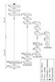
- WO2024075705A1 WO2024075705A1 PCT/JP2023/035961 JP2023035961W WO2024075705A1 WO 2024075705 A1 WO2024075705 A1 WO 2024075705A1 JP 2023035961 W JP2023035961 W JP 2023035961W WO 2024075705 A1 WO2024075705 A1 WO 2024075705A1
- Authority
- WO
- WIPO (PCT)
- Prior art keywords
- image
- sinogram
- cnn
- image processing
- subject
- Prior art date
- Legal status (The legal status is an assumption and is not a legal conclusion. Google has not performed a legal analysis and makes no representation as to the accuracy of the status listed.)
- Ceased
Links
Images


Classifications
-
- A—HUMAN NECESSITIES
- A61—MEDICAL OR VETERINARY SCIENCE; HYGIENE
- A61B—DIAGNOSIS; SURGERY; IDENTIFICATION
- A61B6/00—Apparatus or devices for radiation diagnosis; Apparatus or devices for radiation diagnosis combined with radiation therapy equipment
- A61B6/02—Arrangements for diagnosis sequentially in different planes; Stereoscopic radiation diagnosis
- A61B6/03—Computed tomography [CT]
- A61B6/037—Emission tomography
-
- G—PHYSICS
- G01—MEASURING; TESTING
- G01T—MEASUREMENT OF NUCLEAR OR X-RADIATION
- G01T1/00—Measuring X-radiation, gamma radiation, corpuscular radiation, or cosmic radiation
- G01T1/16—Measuring radiation intensity
- G01T1/161—Applications in the field of nuclear medicine, e.g. in vivo counting
-
- A—HUMAN NECESSITIES
- A61—MEDICAL OR VETERINARY SCIENCE; HYGIENE
- A61B—DIAGNOSIS; SURGERY; IDENTIFICATION
- A61B6/00—Apparatus or devices for radiation diagnosis; Apparatus or devices for radiation diagnosis combined with radiation therapy equipment
- A61B6/02—Arrangements for diagnosis sequentially in different planes; Stereoscopic radiation diagnosis
- A61B6/03—Computed tomography [CT]
-
- A—HUMAN NECESSITIES
- A61—MEDICAL OR VETERINARY SCIENCE; HYGIENE
- A61B—DIAGNOSIS; SURGERY; IDENTIFICATION
- A61B6/00—Apparatus or devices for radiation diagnosis; Apparatus or devices for radiation diagnosis combined with radiation therapy equipment
- A61B6/52—Devices using data or image processing specially adapted for radiation diagnosis
- A61B6/5205—Devices using data or image processing specially adapted for radiation diagnosis involving processing of raw data to produce diagnostic data
-
- A—HUMAN NECESSITIES
- A61—MEDICAL OR VETERINARY SCIENCE; HYGIENE
- A61B—DIAGNOSIS; SURGERY; IDENTIFICATION
- A61B6/00—Apparatus or devices for radiation diagnosis; Apparatus or devices for radiation diagnosis combined with radiation therapy equipment
- A61B6/52—Devices using data or image processing specially adapted for radiation diagnosis
- A61B6/5258—Devices using data or image processing specially adapted for radiation diagnosis involving detection or reduction of artifacts or noise
-
- G—PHYSICS
- G06—COMPUTING OR CALCULATING; COUNTING
- G06N—COMPUTING ARRANGEMENTS BASED ON SPECIFIC COMPUTATIONAL MODELS
- G06N3/00—Computing arrangements based on biological models
- G06N3/02—Neural networks
- G06N3/04—Architecture, e.g. interconnection topology
-
- G—PHYSICS
- G06—COMPUTING OR CALCULATING; COUNTING
- G06N—COMPUTING ARRANGEMENTS BASED ON SPECIFIC COMPUTATIONAL MODELS
- G06N3/00—Computing arrangements based on biological models
- G06N3/02—Neural networks
- G06N3/04—Architecture, e.g. interconnection topology
- G06N3/045—Combinations of networks
-
- G—PHYSICS
- G06—COMPUTING OR CALCULATING; COUNTING
- G06N—COMPUTING ARRANGEMENTS BASED ON SPECIFIC COMPUTATIONAL MODELS
- G06N3/00—Computing arrangements based on biological models
- G06N3/02—Neural networks
- G06N3/04—Architecture, e.g. interconnection topology
- G06N3/0464—Convolutional networks [CNN, ConvNet]
-
- G—PHYSICS
- G06—COMPUTING OR CALCULATING; COUNTING
- G06N—COMPUTING ARRANGEMENTS BASED ON SPECIFIC COMPUTATIONAL MODELS
- G06N3/00—Computing arrangements based on biological models
- G06N3/02—Neural networks
- G06N3/04—Architecture, e.g. interconnection topology
- G06N3/048—Activation functions
-
- G—PHYSICS
- G06—COMPUTING OR CALCULATING; COUNTING
- G06N—COMPUTING ARRANGEMENTS BASED ON SPECIFIC COMPUTATIONAL MODELS
- G06N3/00—Computing arrangements based on biological models
- G06N3/02—Neural networks
- G06N3/08—Learning methods
-
- G—PHYSICS
- G06—COMPUTING OR CALCULATING; COUNTING
- G06T—IMAGE DATA PROCESSING OR GENERATION, IN GENERAL
- G06T12/00—Tomographic reconstruction from projections
-
- G—PHYSICS
- G06—COMPUTING OR CALCULATING; COUNTING
- G06T—IMAGE DATA PROCESSING OR GENERATION, IN GENERAL
- G06T12/00—Tomographic reconstruction from projections
- G06T12/20—Inverse problem, i.e. transformations from projection space into object space
-
- A—HUMAN NECESSITIES
- A61—MEDICAL OR VETERINARY SCIENCE; HYGIENE
- A61B—DIAGNOSIS; SURGERY; IDENTIFICATION
- A61B6/00—Apparatus or devices for radiation diagnosis; Apparatus or devices for radiation diagnosis combined with radiation therapy equipment
- A61B6/02—Arrangements for diagnosis sequentially in different planes; Stereoscopic radiation diagnosis
- A61B6/03—Computed tomography [CT]
- A61B6/032—Transmission computed tomography [CT]
-
- A—HUMAN NECESSITIES
- A61—MEDICAL OR VETERINARY SCIENCE; HYGIENE
- A61B—DIAGNOSIS; SURGERY; IDENTIFICATION
- A61B6/00—Apparatus or devices for radiation diagnosis; Apparatus or devices for radiation diagnosis combined with radiation therapy equipment
- A61B6/50—Apparatus or devices for radiation diagnosis; Apparatus or devices for radiation diagnosis combined with radiation therapy equipment specially adapted for specific body parts; specially adapted for specific clinical applications
- A61B6/501—Apparatus or devices for radiation diagnosis; Apparatus or devices for radiation diagnosis combined with radiation therapy equipment specially adapted for specific body parts; specially adapted for specific clinical applications for diagnosis of the head, e.g. neuroimaging or craniography
-
- G—PHYSICS
- G06—COMPUTING OR CALCULATING; COUNTING
- G06T—IMAGE DATA PROCESSING OR GENERATION, IN GENERAL
- G06T2207/00—Indexing scheme for image analysis or image enhancement
- G06T2207/10—Image acquisition modality
- G06T2207/10072—Tomographic images
- G06T2207/10081—Computed x-ray tomography [CT]
-
- G—PHYSICS
- G06—COMPUTING OR CALCULATING; COUNTING
- G06T—IMAGE DATA PROCESSING OR GENERATION, IN GENERAL
- G06T2207/00—Indexing scheme for image analysis or image enhancement
- G06T2207/20—Special algorithmic details
- G06T2207/20084—Artificial neural networks [ANN]
-
- G—PHYSICS
- G06—COMPUTING OR CALCULATING; COUNTING
- G06T—IMAGE DATA PROCESSING OR GENERATION, IN GENERAL
- G06T2211/00—Image generation
- G06T2211/40—Computed tomography
- G06T2211/441—AI-based methods, deep learning or artificial neural networks
Definitions
- This disclosure relates to an apparatus and method for creating a tomographic image of a subject based on coincidence counting information collected by a radiation tomography apparatus.
- Radiation tomography devices capable of acquiring tomographic images of a subject (living organism) include PET (Positron Emission Tomography) devices and SPECT (Single Photon Emission Computed Tomography) devices.
- the PET device is equipped with a detection section that has a large number of small radiation detectors arranged around the measurement space in which the subject is placed.
- the PET device uses coincidence counting to detect photon pairs with energy of 511 keV that are generated as a result of electron-positron annihilation in a subject that has been administered a positron-emitting isotope (RI source), and collects this coincidence counting information.
- RI source positron-emitting isotope
- a tomographic image can be reconstructed that shows the spatial distribution of the frequency of photon pair occurrence in the measurement space (i.e., the spatial distribution of the RI source).
- Such PET devices play an important role in fields such as nuclear medicine, and can be used to study, for example, biological functions and higher-level brain functions.
- Non-Patent Document 1 reconstructs a tomographic image using the Deep Image Prior technique, which uses a convolutional neural network, a type of deep neural network.
- the Convolutional Neural Network is referred to as "CNN”
- the Deep Image Prior technique is referred to as "DIP technique.”
- DIP technology takes advantage of the property of CNN that meaningful structures in an image are learned faster than random noise (i.e., random noise is difficult to learn). DIP technology makes it possible to obtain cross-sectional images with reduced noise.
- Non-Patent Document 1 the image processing method described in Non-Patent Document 1 is as follows: A sinogram (hereinafter referred to as a "measured sinogram") is created based on a large amount of coincidence counting information collected about the subject.
- a sinogram hereinafter referred to as a "calculated sinogram” is created by performing a forward projection calculation (Radon transform) on the image output from the CNN.
- the CNN is trained based on the error evaluation results.
- the calculated sinogram gradually approaches the measured sinogram, and the output image from the CNN approaches the tomographic image of the subject.
- This image processing method includes a process of forward projecting the CNN output image onto a calculated sinogram, but does not include a process of back projecting the measured sinogram onto a tomographic image, making it possible to obtain a tomographic image with reduced noise.
- the sinogram is expressed as a histogram showing the frequency with which coincidence information was obtained (frequency of occurrence of coincidence events) in a space (sinogram space) represented by four variables r, ⁇ , z, and ⁇ .
- the variable r represents the distance from the central axis to the coincidence line (the line connecting the two detectors that simultaneously counted the photon pairs).
- the variable ⁇ represents the azimuth angle of the coincidence line.
- the variable z represents the central axial position of the midpoint of the coincidence line. Additionally, the variable ⁇ represents the central axial distance between the two detectors that simultaneously counted the photon pairs.
- Noise reduction processing using DIP technology has excellent noise reduction performance, but it has the problem of image quality degradation due to overlearning of the CNN.
- DIP technology takes advantage of the property of CNN that random noise is difficult to learn, but as the number of times CNN learns increases, random noise is also restored. In this way, overlearning of the CNN causes image quality to deteriorate as random noise is also restored.
- the present invention aims to provide an image processing device and an image processing method that can suppress image quality degradation caused by CNN overlearning in noise reduction processing using DIP technology when creating a tomographic image of a subject by training a CNN based on the evaluation results of the error between a calculated sinogram and a measured sinogram, thereby obtaining a tomographic image with reduced noise.
- An embodiment of the present invention is an image processing device.
- the image processing device creates a tomographic image of the subject based on coincidence information collected by a radiation tomography device having multiple detectors arranged around a measurement space in which a subject administered with an RI radiation source is placed, and includes: (1) a sinogram creation unit that creates a sinogram based on the coincidence information collected by the radiation tomography device; (2) a CNN processing unit that inputs an input image to a convolutional neural network and creates an output image by the convolutional neural network; (3) a forward projection calculation unit that creates a sinogram by forward projection calculation of the output image; and (4) a CNN learning unit that uses an evaluation function including an error evaluation term that represents an evaluation value regarding the error between the sinogram created by the sinogram creation unit and the sinogram created by the forward projection calculation unit, and a regularization term that represents an evaluation value regarding the difference in pixel values between adjacent pixels in the output image, and trains the convolutional neural network based on the value of this evaluation function, and the output
- An embodiment of the present invention is a radiation tomography system.
- the radiation tomography system includes a radiation tomography device having a plurality of detectors arranged around a measurement space in which a subject administered with an RI radiation source is placed, and collecting coincidence counting information, and an image processing device having the above-described configuration that creates a tomographic image of the subject based on the coincidence counting information collected by the radiation tomography device.
- An embodiment of the present invention is an image processing method.
- the image processing method is an image processing method for creating a tomographic image of a subject based on coincidence information collected by a radiation tomography apparatus having multiple detectors arranged around a measurement space in which a subject to which an RI radiation source has been administered is placed, and includes: (1) a sinogram creation step for creating a sinogram based on the coincidence information collected by the radiation tomography apparatus; (2) a CNN processing step for inputting an input image to a convolutional neural network and creating an output image by the convolutional neural network; (3) a forward projection calculation step for creating a sinogram by forward projection calculation of the output image; and (4) a CNN learning step for learning a convolutional neural network based on the value of an evaluation function that includes an error evaluation term that represents an evaluation value regarding the error between the sinogram created in the sinogram creation step and the sinogram created in the forward projection calculation step, and a regularization term that represents an evaluation value regarding the difference in pixel values between adjacent pixels in the output image.
- a CNN when a CNN is trained based on the evaluation results of the error between the calculated sinogram and the measured sinogram to create a tomographic image of a subject, degradation of image quality caused by CNN over-training can be suppressed in noise reduction processing using DIP technology, and a tomographic image with reduced noise can be obtained.
- FIG. 1 is a diagram showing the configuration of a radiation tomography system 1.
- FIG. 2 is a diagram illustrating an example of the configuration of a CNN.
- FIG. 3 is a flow chart of an image processing method.
- FIG. 4 is a diagram showing a comparison between examples of the calculated sinogram 24 when no block division is performed and the calculated sinograms 24 1 to 24 16 when block division is performed, in which (a) is a diagram showing a schematic diagram of the calculated sinogram 24 when no block division is performed, and (b) is a diagram showing a schematic diagram of the calculated sinograms 24 1 to 24 16 when block division is performed.
- FIG. 5 is a diagram illustrating adjacent pixels in an output image.
- FIG. 6 shows a tomographic image of the brain obtained by image processing method 1.
- FIG. 7 shows a tomographic image of the brain obtained by image processing method 2.
- FIG. 8 shows a tomographic image of the brain obtained by image processing method 3.
- FIG. 1 is a diagram showing the configuration of a radiation tomography system 1.
- the radiation tomography system 1 includes a radiation tomography device 2 and an image processing device 10.
- the image processing device 10 includes a sinogram creation unit 11, a CNN processing unit 12, a convolution integral unit 13, a forward projection calculation unit 14, and a CNN learning unit 15.
- the input image, output image, and tomographic image may be either two-dimensional or three-dimensional images, but the following description will assume that these images are three-dimensional images.
- the measured sinogram and calculated sinogram may or may not be divided into multiple blocks, but the following description will mainly focus on the case where these sinograms are divided into multiple blocks.
- the radiation tomography apparatus 2 is an apparatus that collects coincidence counting information for reconstructing a tomographic image of the subject.
- Examples of the radiation tomography apparatus 2 include a PET apparatus and a SPECT apparatus. In the following description, the radiation tomography apparatus 2 will be described as a PET apparatus.
- the radiation tomography apparatus 2 is equipped with a detection section having a large number of small radiation detectors arranged around the measurement space in which the subject is placed.
- the radiation tomography apparatus 2 detects photon pairs with energy of 511 keV that are generated in association with the annihilation of electrons and positrons in a subject administered with an RI radiation source by a coincidence method using the detection section, and collects this coincidence information.
- the radiation tomography apparatus 2 then outputs this collected coincidence information to the image processing device 10.
- the image processing device 10 includes a GPU (Graphics Processing Unit) that performs processing using a convolutional neural network (CNN), an input unit (e.g., a keyboard or mouse) that accepts input from an operator, a display unit (e.g., a liquid crystal display) that displays images, etc., and a storage unit that stores programs and data for executing various processes.
- a GPU Graphics Processing Unit
- CNN convolutional neural network
- input unit e.g., a keyboard or mouse
- a display unit e.g., a liquid crystal display
- storage unit that stores programs and data for executing various processes.
- a computer having a CPU, RAM, ROM, hard disk drive, etc. is used as the image processing device 10.
- the sinogram creation unit 11 creates a measured sinogram 21 based on the coincidence counting information collected by the radiation tomography apparatus 2. At this time, the sinogram creation unit 11 creates measured sinograms 21 1 to 21 K divided into a plurality of (K) blocks.
- the measured sinogram 21 k is the measured sinogram of the k-th block of the K blocks.
- K is an integer of 2 or more, and k is an integer of 1 to K.
- the divided measured sinograms 21 1 to 21 K are combined to form the entire measured sinogram 21.
- the CNN processing unit 12 inputs a three-dimensional input image 20 to a CNN, which then creates a three-dimensional output image 22.
- the three-dimensional input image 20 may be an image that represents morphological information of a subject, an MRI image, a CT image, or a static PET image of the subject, or a random noise image.
- the convolution integral unit 13 performs convolution integral of a point spread function on the three-dimensional output image 22 created by the CNN processing unit 12 to create a new three-dimensional output image 23.
- the point spread function is a function that represents the response (impulse response) of a radiation tomography device to a point radiation source, and is generally represented by a Gaussian function or an asymmetric Gaussian function that has a different blur depending on the position in the field of view modeled from the actual measurement data of the point radiation source.
- the forward projection calculation unit 14 performs forward projection calculation on the three-dimensional output image 23 to create a calculated sinogram 24. At this time, the forward projection calculation unit 14 creates calculated sinograms 24 1 to 24 K divided into K blocks.
- the calculated sinogram 24 k is the calculated sinogram of the k-th block out of the K blocks.
- the divided calculated sinograms 24 1 to 24 K are combined to form the entire calculated sinogram 24.
- the calculated sinogram 24 is divided into blocks in the same manner as the measured sinogram 21.
- the calculated sinogram 24 k of the kth block and the measured sinogram 21 k of the kth block are sinograms of a common region in the entire sinogram space.
- the manner of block division is arbitrary, and block division may be performed for any one or more variables among the four variables expressing the sinogram space.
- the sizes of the K blocks may be different or the same.
- the CNN training unit 15 evaluates the error between the measured sinogram 21 k and the calculated sinogram 24 k for each of the K blocks, and trains the CNN based on the error evaluation results for each of the K blocks.
- the 3D output image 22 created by the CNN processing unit 12 after multiple repetitions of the processing of the CNN processing unit 12, the convolution integration unit 13, the forward projection calculation unit 14, and the CNN learning unit 15 is the 3D tomographic image of the subject.
- the 3D output image 23 created by the convolution integration unit 13 may also be the 3D tomographic image of the subject. Since the measured sinogram 21 reflects the response function of the radiation tomography device, it is preferable to use the 3D output image 22 before the convolution integration of the point spread function by the convolution integration unit 13 as the 3D tomographic image of the subject.
- the convolution integration unit 13 may be provided as the final layer of the CNN, or may be provided separately from the CNN. When the convolution integration unit 13 is provided as the final layer of the CNN, the weighting coefficient of the convolution integration unit 13 is maintained constant during CNN training. The convolution integration unit 13 does not have to be provided. When the convolution integration unit 13 is not provided, the forward projection calculation unit 14 performs a forward projection calculation of the three-dimensional output image 22 output from the CNN processing unit 12 to create a calculated sinogram 24.
- Figure 2 shows an example of a CNN configuration.
- the CNN shown in this figure has a three-dimensional U-net structure that includes an encoder and a decoder. This figure shows the size of each layer of the CNN, with the number of pixels of the three-dimensional input image 20 input to the CNN being NxNx64.
- FIG. 3 is a flowchart of the image processing method.
- the image processing method includes a sinogram creation step S1 performed by the sinogram creation unit 11, a CNN processing step S2 performed by the CNN processing unit 12, a convolution integration step S3 performed by the convolution integration unit 13, a forward projection calculation step S4 performed by the forward projection calculation unit 14, and a CNN learning step S5 performed by the CNN learning unit 15.
- a sinogram creation step S1 measured sinograms 21 1 to 21 K divided into K blocks are created based on coincidence counting information collected by the radiation tomography apparatus 2.
- a CNN processing step S2 a three-dimensional input image 20 is input to a CNN, which creates a three-dimensional output image 22.
- a convolution integration step S3 a convolution integration of a point spread function is performed on the three-dimensional output image 22 created in the CNN processing step S2, to create a new three-dimensional output image 23.
- a forward projection calculation step S4 a forward projection calculation is performed on the three-dimensional output image 23 to generate calculated sinograms 24 1 to 24 K divided into K blocks.
- a CNN learning step S5 an error between the measured sinogram 21 k and the calculated sinogram 24 k for each of the K blocks is evaluated, and a CNN is trained based on the error evaluation results for each of the K blocks.
- the three-dimensional output image 22 created in the CNN processing step S2 is the three-dimensional tomographic image of the subject.
- the three-dimensional output image 23 created in the convolution integral step S3 may be the three-dimensional tomographic image of the subject. Note that the convolution integral step S3 does not have to be provided.
- the processing by the CNN is denoted as f, the three-dimensional input image 20 input to the CNN as z, and the weighting coefficient parameter representing the learning state of the CNN as ⁇ . ⁇ changes as the learning of the CNN progresses.
- the three-dimensional output image 22 output from the CNN when a three-dimensional input image z is input to a CNN with a weighting coefficient of ⁇ is denoted as x.
- the three-dimensional output image x is expressed by the following equation (1). In the CNN processing step, the processing represented by this equation is performed to create the three-dimensional output image x.
- the point spread function is convolved with the 3D output image x created in the CNN processing step to create a new 3D output image x.
- the 3D output image x after the convolution is written as PSF(f( ⁇
- the three-dimensional output image x is forward projected to generate a calculated sinogram 24.
- the calculated sinogram 24 is denoted as y
- a projection matrix for performing forward projection calculation (Radon transform) from the three-dimensional output image x to the calculated sinogram y is denoted as P.
- the projection matrix is also called a system matrix or detection probability.
- the measured sinogram 21 is set to y0 , the error between the measured sinogram y0 and the calculated sinogram y (the above formula (2)) is evaluated, and the CNN is trained based on the error evaluation result.
- the process performed in the CNN learning step is expressed by the following formula (3).
- the constrained optimization problem of this formula is a problem of optimizing the CNN parameter ⁇ so as to reduce the value of the evaluation function E(y; y0 ) under the constraint that the three-dimensional output image x created by the CNN is a tomographic image of the subject.
- the constrained optimization problem of the formula (3) can be transformed into an unconstrained optimization problem of the following formula (4).
- the evaluation function E can be any function, and for example, the L1 norm, the L2 norm, or the negative log-likelihood in the Poisson distribution can be used.
- the formula (4) can be transformed into the following formula (5).
- m is a binary mask function that has a value of 1 in a region in the sinogram space where it is possible to collect coincidence counting information, and has a value of 0 in a region in the sinogram space where it is impossible to collect coincidence counting information.
- Formula (6) selectively evaluates the error in a region in the sinogram space where it is possible to collect coincidence counting information by taking the Hadamard product of the error (y-y 0 ) and the binary mask function m.
- the CNN processing step By repeating the CNN processing step, the convolution integral step, the forward projection calculation step, and the CNN learning step multiple times to solve this optimization problem for the CNN parameter ⁇ , the calculated sinogram y approaches the measured sinogram y0 , and the three-dimensional output image x created by the CNN approaches the tomographic image of the subject.
- a forward projection calculation step a three-dimensional output image x is forward projected to generate calculated sinograms 24 1 to 24 K divided into K blocks.
- the calculated sinogram 24 k of the kth block is denoted by y k
- a projection matrix for performing a forward projection calculation (Radon transform) from the three-dimensional output image x to the calculated sinogram y k is denoted by P k .
- the processing performed in the forward projection calculation step is expressed by the following formula (7).
- the measured sinogram 21 k of the kth block is defined as y 0 k
- the error between the measured sinogram y 0 k and the calculated sinogram y k is evaluated for each of the K blocks, and the CNN is trained based on the error evaluation results for each of the K blocks.
- the process performed in the CNN learning step is expressed by the unconstrained optimization problem of the following formula (8).
- formula (8) can be transformed into the following formula (9).
- the error is selectively evaluated in a region in the sinogram space where coincidence information can be collected, it is expressed by the unconstrained optimization problem of the following formula (10).
- m k is a binary mask function in the kth block.
- the CNN processing step By repeating the CNN processing step, the convolution integral step, the forward projection calculation step, and the CNN learning step multiple times to solve this optimization problem for the CNN parameter ⁇ , the calculated sinogram y k for each of the K blocks approaches the measured sinogram y 0k , and the three-dimensional output image x created by the CNN approaches the tomographic image of the subject.
- GPUs are used in processing using CNNs.
- GPUs are arithmetic processing devices specialized for image processing, and have an arithmetic unit and RAM integrated on a single semiconductor chip.
- Various types of data used during arithmetic processing by the arithmetic unit of the GPU must be stored in the RAM of the GPU.
- the data that needs to be stored in the GPU RAM includes, for example, CNN input images, CNN output images, weight coefficients that represent the CNN learning state, feature maps, measured sinograms, calculated sinograms, parameters required for forward projection calculations, etc., and requires a huge amount of storage capacity.
- CNN input images CNN output images
- weight coefficients that represent the CNN learning state
- feature maps feature maps
- measured sinograms calculated sinograms
- parameters required for forward projection calculations etc.
- the number of pixels of the three-dimensional output image created by the CNN is 128 ⁇ 128 ⁇ 64
- the number of pixels of the sinogram space is 128 ⁇ 128 ⁇ 64 ⁇ 19.
- Fig. 4 is a diagram showing a comparison between examples of a calculated sinogram 24 when no block division is performed and calculated sinograms 24 1 to 24 16 when block division is performed.
- Fig. 4(a) shows a schematic diagram of the calculated sinogram 24 when no block division is performed.
- Fig. 4(b) shows a schematic diagram of the calculated sinograms 24 1 to 24 16 when block division is performed.
- the number of pixels of the calculated sinogram 24 k of each block when dividing into blocks is 128 ⁇ 8 ⁇ 64 ⁇ 19, which is 1/16 of the number of pixels of the calculated sinogram 24 when dividing into blocks is not performed. Furthermore, the number of elements of the projection matrix P k for performing forward projection calculation from the three-dimensional output image to the calculated sinogram 24 k of the kth block when dividing into blocks is 1/16 of the number of elements of the projection matrix P for performing forward projection calculation from the three-dimensional output image to the calculated sinogram 24 when dividing into blocks is not performed.
- the memory capacity required to store the data used in the forward projection calculation can be reduced compared to when dividing into blocks is not performed, and this data can be stored in the GPU's RAM. Therefore, when dividing into blocks, it becomes easier to perform 3D forward projection calculations from the CNN output image to the calculated sinogram, and it is possible to easily create 3D tomographic images of the subject by training the CNN based on the evaluation results of the error between the calculated sinogram and the measured sinogram.
- the evaluation function used by the CNN learning unit 15 in the CNN learning step S5 will be further explained.
- an evaluation function that includes a regularization term in addition to this error evaluation term.
- the regularization term is for suppressing CNN overlearning, and represents an evaluation value related to the difference in pixel values between adjacent pixels in the output image.
- the evaluation function when the sinogram is not divided into blocks is given by the following formula (11) instead of the above formula (5). Also, the evaluation function when the sinogram is divided into blocks is given by the following formula (12) instead of the above formula (9).
- the first term on the right hand side is an error evaluation term
- the second term on the right hand side is a regularization term.
- This regularization term penalizes the difference in pixel values between adjacent pixels in the output image.
- ⁇ is a hyperparameter that adjusts the degree of the effect of regularization. The smaller ⁇ is, the smaller the effect of regularization is. The larger ⁇ is, the greater the effect of regularization (i.e., the effect of suppressing CNN overlearning).
- the regularization term may represent an evaluation value regarding the difference in pixel values between adjacent pixels in the output image 22 (f( ⁇
- the neighbors of a pixel include neighbors in each of two mutually perpendicular directions, and preferably also neighbors in a diagonal direction.
- the number of neighbors of a pixel is eight, excluding pixels at the edges or corners of the image.
- the neighbors of a pixel include neighbors in each of three mutually orthogonal directions, and preferably also neighbors in diagonal directions.
- the number of neighbors of a pixel is 26, excluding pixels at the edges or corners of the image.
- FIG. 5 is a diagram explaining adjacent pixels in an output image.
- This diagram shows the output image as a two-dimensional image, with 3 ⁇ 3 pixels shown.
- the difference in pixel values between adjacent pixels with respect to this center pixel is expressed as
- the regularization term represents an evaluation value regarding the difference in pixel values for all combinations of adjacent pixels in the output image.
- the regularization term may be expressed by various formulas as long as it represents an evaluation value related to the difference in pixel values between adjacent pixels in the output image.
- the regularization term is expressed by the following formula (13).
- N j represents a set of pixels k adjacent to pixel j.
- ⁇ represents the magnitude of change in the value of the regularization term with respect to a change in pixel value ⁇ j .
- This formula (13) includes a term of the difference in pixel values between adjacent pixels in the numerator and a term of the sum of the pixel values of adjacent pixels in the denominator, and represents an evaluation value related to the relative difference in pixel values between adjacent pixels in the output image.
- equation (13) is similar to the equation described in Non-Patent Document 2. However, in Non-Patent Document 2, an equation similar to equation (13) is used in the process of reconstructing a tomographic image of a subject based on coincidence counting information collected by a PET device, and is not used in the noise reduction process of the tomographic image by DIP technology.
- Non-Patent Document 3 Gibbs prior (Non-Patent Document 3) or total variation (Non-Patent Document 4) may be used. Note that these documents also describe the technology for reconstructing and processing a tomographic image of a subject, and do not describe the technology for performing noise reduction processing on a tomographic image using DIP technology.
- image processing method 1 a tomographic image was reconstructed using the ML-EM (Maximum Likelihood Expectation Maximization) method, which is a common image reconstruction method.
- image processing method 2 a tomographic image was reconstructed using the evaluation function in equation (9) above in the image processing method described with reference to Figures 1 to 4.
- image processing method 3 a tomographic image was reconstructed using the evaluation functions in equations (12) and (13) above in the image processing method described with reference to Figures 1 to 4.
- the phantom image used was a 3D brain image obtained from BrainWeb (https://brainweb.bic.mni.mcgill.ca/brainweb/) in which a simulated tumor was embedded in the white matter.
- the number of pixels in the phantom image was 128 x 128 x 64.
- the number of pixels in the sinogram space was 128 x 128 x 64 x 19, and the sinogram space was divided equally into two blocks.
- the error evaluation term of the evaluation function used in image processing methods 2 and 3 was the mean squared error (MSE).
- MSE mean squared error
- the input image input to the CNN was a three-dimensional random noise image.
- the number of iterations was 2000, and in image processing method 1, the number of iterations was 50.
- FIG. 6 shows a tomographic image of the brain obtained by image processing method 1.
- FIG. 7 shows a tomographic image of the brain obtained by image processing method 2.
- FIG. 8 shows a tomographic image of the brain obtained by image processing method 3.
- PSNR Peak Signal to Noise Ratio
- dB decibels
- the image processing device and image processing method are not limited to the above-mentioned embodiments and configuration examples, and various modifications are possible.
- the image processing device of the first aspect is an image processing device that creates a tomographic image of a subject based on coincidence information collected by a radiation tomography device having a plurality of detectors arranged around a measurement space in which a subject administered with an RI radiation source is placed, and includes: (1) a sinogram creation unit that creates a sinogram based on the coincidence information collected by the radiation tomography device; (2) a CNN processing unit that inputs an input image to a convolutional neural network and creates an output image by the convolutional neural network; (3) a forward projection calculation unit that creates a sinogram by forward projection calculation of the output image; and (4) a CNN learning unit that uses an evaluation function including an error evaluation term that represents an evaluation value regarding the error between the sinogram created by the sinogram creation unit and the sinogram created by the forward projection calculation unit, and a regularization term that represents an evaluation value regarding the difference in pixel values between adjacent pixels in the output image, and trains the convolutional neural network based on the value of this evaluation
- the sinogram creation unit creates a sinogram divided into multiple blocks based on coincidence counting information collected by the radiation tomography device
- the forward projection calculation unit performs forward projection calculation on the output image to create a sinogram divided into multiple blocks
- the CNN learning unit may be configured to train a convolutional neural network based on the value of the evaluation function for each of the multiple blocks.
- the tomographic image, the input image, and the output image may each be a three-dimensional image.
- a convolution integral unit may be further provided that performs a convolution integral of the point spread function on the output image
- the forward projection calculation unit may be configured to perform a forward projection calculation on the output image after processing by the convolution integral unit.
- the CNN learning unit may be configured to evaluate the error using an error evaluation term in a region in the sinogram space where coincidence information can be collected by the radiation tomography device.
- the CNN processing unit may be configured to input an image representing morphological information of the subject as an input image to the convolutional neural network.
- the CNN processing unit may be configured to input an MRI image of the subject as an input image to the convolutional neural network.
- the CNN processing unit may be configured to input a CT image of the subject as an input image to the convolutional neural network.
- the CNN processing unit may be configured to input a static PET image of the subject as an input image to the convolutional neural network.
- the CNN processing unit may be configured to input a random noise image as an input image to the convolutional neural network.
- the radiation tomography system includes a radiation tomography device having a plurality of detectors arranged around a measurement space in which a subject administered with an RI radiation source is placed, and collecting coincidence counting information, and an image processing device of the above configuration that creates a tomographic image of the subject based on the coincidence counting information collected by the radiation tomography device.
- the image processing method of the first aspect is an image processing method for creating a tomographic image of a subject based on coincidence counting information collected by a radiation tomography apparatus having a plurality of detectors arranged around a measurement space in which a subject to which an RI radiation source has been administered is placed, and includes: (1) a sinogram creation step for creating a sinogram based on the coincidence counting information collected by the radiation tomography apparatus; (2) a CNN processing step for inputting an input image into a convolutional neural network and creating an output image by the convolutional neural network; and (3) a forward projection calculation of the output image to create a sinogram.
- the method includes a forward projection calculation step for creating an inogram, and (4) a CNN learning step for using an evaluation function including an error evaluation term that represents an evaluation value related to the error between the sinogram created in the sinogram creation step and the sinogram created in the forward projection calculation step, and a regularization term that represents an evaluation value related to the difference in pixel values between adjacent pixels in the output image, and for training a convolutional neural network based on the value of this evaluation function, and the output image after the CNN processing step, the forward projection calculation step, and the CNN learning step are each repeated multiple times is used as a tomographic image of the subject.
- a sinogram divided into a plurality of blocks is created based on coincidence counting information collected by a radiation tomography device
- a sinogram divided into a plurality of blocks is created by performing forward projection calculation on the output image
- a convolutional neural network may be trained based on the value of an evaluation function for each of the plurality of blocks.
- the tomographic image, the input image, and the output image may each be a three-dimensional image.
- a convolution integral step may be further provided in which a convolution integral of a point spread function is performed on the output image, and in the forward projection calculation step, a forward projection calculation may be performed on the output image after processing in the convolution integral step.
- an error in the configuration of any of the first to fourth aspects, in the CNN learning step, an error may be evaluated using an error evaluation term in an area in the sinogram space where coincidence information can be collected by the radiation tomography device.
- an image representing morphological information of the subject may be input as an input image to a convolutional neural network.
- the CNN processing step may be configured to input an MRI image of the subject as an input image to the convolutional neural network.
- the CNN processing step may be configured to input a CT image of the subject as an input image to a convolutional neural network.
- a static PET image of the subject may be input as an input image to a convolutional neural network in the CNN processing step.
- a random noise image may be input as an input image to the convolutional neural network in the CNN processing step.
- the present invention can be used as an image processing device and image processing method that can suppress image quality degradation caused by CNN overlearning in noise reduction processing using DIP technology when creating a tomographic image of a subject by training a CNN based on the evaluation results of the error between a calculated sinogram and an actual sinogram, thereby obtaining a tomographic image with reduced noise.
Landscapes
- Engineering & Computer Science (AREA)
- Physics & Mathematics (AREA)
- Health & Medical Sciences (AREA)
- Life Sciences & Earth Sciences (AREA)
- Theoretical Computer Science (AREA)
- General Health & Medical Sciences (AREA)
- Biomedical Technology (AREA)
- Molecular Biology (AREA)
- General Physics & Mathematics (AREA)
- Biophysics (AREA)
- Medical Informatics (AREA)
- Mathematical Physics (AREA)
- Artificial Intelligence (AREA)
- Data Mining & Analysis (AREA)
- Computing Systems (AREA)
- General Engineering & Computer Science (AREA)
- Computational Linguistics (AREA)
- Software Systems (AREA)
- Evolutionary Computation (AREA)
- Optics & Photonics (AREA)
- High Energy & Nuclear Physics (AREA)
- Nuclear Medicine, Radiotherapy & Molecular Imaging (AREA)
- Surgery (AREA)
- Pathology (AREA)
- Radiology & Medical Imaging (AREA)
- Heart & Thoracic Surgery (AREA)
- Animal Behavior & Ethology (AREA)
- Public Health (AREA)
- Veterinary Medicine (AREA)
- Spectroscopy & Molecular Physics (AREA)
- Computer Vision & Pattern Recognition (AREA)
- Nuclear Medicine (AREA)
- Apparatus For Radiation Diagnosis (AREA)
- Image Analysis (AREA)
Abstract
Description
Claims (21)
- RI線源が投与された被検体が置かれる測定空間を囲んで配置された複数の検出器を有する放射線断層撮影装置により収集された同時計数情報に基づいて、前記被検体の断層画像を作成する画像処理装置であって、
前記放射線断層撮影装置により収集された同時計数情報に基づいてサイノグラムを作成するサイノグラム作成部と、
畳み込みニューラルネットワークに入力画像を入力させて前記畳み込みニューラルネットワークにより出力画像を作成するCNN処理部と、
前記出力画像を順投影計算してサイノグラムを作成する順投影計算部と、
前記サイノグラム作成部により作成されたサイノグラムと前記順投影計算部により作成されたサイノグラムとの間の誤差に関する評価値を表す誤差評価項と、前記出力画像における隣接画素間の画素値の差に関する評価値を表す正則化項と、を含む評価関数を用い、この評価関数の値に基づいて前記畳み込みニューラルネットワークを学習させるCNN学習部と、
を備え、
前記CNN処理部、前記順投影計算部および前記CNN学習部それぞれの処理を複数回繰り返し行った後の前記出力画像を前記被検体の断層画像とする、
画像処理装置。 - 前記サイノグラム作成部は、前記放射線断層撮影装置により収集された同時計数情報に基づいて、複数のブロックに分割されたサイノグラムを作成し、
前記順投影計算部は、前記出力画像を順投影計算して、前記複数のブロックに分割されたサイノグラムを作成し、
前記CNN学習部は、前記複数のブロックそれぞれについての前記評価関数の値に基づいて前記畳み込みニューラルネットワークを学習させる、
請求項1に記載の画像処理装置。 - 前記断層画像、前記入力画像および前記出力画像それぞれは3次元の画像である、請求項1または2に記載の画像処理装置。
- 前記出力画像に対し点像分布関数の畳み込み積分を行う畳み込み積分部を更に備え、
前記順投影計算部は、前記畳み込み積分部による処理の後の出力画像を順投影計算する、請求項1~3の何れか1項に記載の画像処理装置。 - 前記CNN学習部は、前記放射線断層撮影装置による同時計数情報収集が可能なサイノグラム空間中の領域において前記誤差評価項により前記誤差を評価する、請求項1~4の何れか1項に記載の画像処理装置。
- 前記CNN処理部は、前記被検体の形態情報を表す画像を前記入力画像として前記畳み込みニューラルネットワークに入力させる、請求項1~5の何れか1項に記載の画像処理装置。
- 前記CNN処理部は、前記被検体のMRI画像を前記入力画像として前記畳み込みニューラルネットワークに入力させる、請求項1~5の何れか1項に記載の画像処理装置。
- 前記CNN処理部は、前記被検体のCT画像を前記入力画像として前記畳み込みニューラルネットワークに入力させる、請求項1~5の何れか1項に記載の画像処理装置。
- 前記CNN処理部は、前記被検体の静的PET画像を前記入力画像として前記畳み込みニューラルネットワークに入力させる、請求項1~5の何れか1項に記載の画像処理装置。
- 前記CNN処理部は、ランダムノイズ画像を前記入力画像として前記畳み込みニューラルネットワークに入力させる、請求項1~5の何れか1項に記載の画像処理装置。
- RI線源が投与された被検体が置かれる測定空間を囲んで配置された複数の検出器を有し同時計数情報を収集する放射線断層撮影装置と、
前記放射線断層撮影装置により収集された同時計数情報に基づいて前記被検体の断層画像を作成する請求項1~10の何れか1項に記載の画像処理装置と、
を備える、放射線断層撮影システム。 - RI線源が投与された被検体が置かれる測定空間を囲んで配置された複数の検出器を有する放射線断層撮影装置により収集された同時計数情報に基づいて、前記被検体の断層画像を作成する画像処理方法であって、
前記放射線断層撮影装置により収集された同時計数情報に基づいてサイノグラムを作成するサイノグラム作成ステップと、
畳み込みニューラルネットワークに入力画像を入力させて前記畳み込みニューラルネットワークにより出力画像を作成するCNN処理ステップと、
前記出力画像を順投影計算してサイノグラムを作成する順投影計算ステップと、
前記サイノグラム作成ステップで作成されたサイノグラムと前記順投影計算ステップで作成されたサイノグラムとの間の誤差に関する評価値を表す誤差評価項と、前記出力画像における隣接画素間の画素値の差に関する評価値を表す正則化項と、を含む評価関数を用い、この評価関数の値に基づいて前記畳み込みニューラルネットワークを学習させるCNN学習ステップと、
を備え、
前記CNN処理ステップ、前記順投影計算ステップおよび前記CNN学習ステップそれぞれの処理を複数回繰り返し行った後の前記出力画像を前記被検体の断層画像とする、
画像処理方法。 - 前記サイノグラム作成ステップにおいて、前記放射線断層撮影装置により収集された同時計数情報に基づいて、複数のブロックに分割されたサイノグラムを作成し、
前記順投影計算ステップにおいて、前記出力画像を順投影計算して、前記複数のブロックに分割されたサイノグラムを作成し、
前記CNN学習ステップにおいて、前記複数のブロックそれぞれについての前記評価関数の値に基づいて前記畳み込みニューラルネットワークを学習させる、
請求項12に記載の画像処理方法。 - 前記断層画像、前記入力画像および前記出力画像それぞれは3次元の画像である、請求項12または13に記載の画像処理方法。
- 前記出力画像に対し点像分布関数の畳み込み積分を行う畳み込み積分ステップを更に備え、
前記順投影計算ステップにおいて、前記畳み込み積分ステップによる処理の後の出力画像を順投影計算する、請求項12~14の何れか1項に記載の画像処理方法。 - 前記CNN学習ステップにおいて、前記放射線断層撮影装置による同時計数情報収集が可能なサイノグラム空間中の領域において前記誤差評価項により前記誤差を評価する、請求項12~15の何れか1項に記載の画像処理方法。
- 前記CNN処理ステップにおいて、前記被検体の形態情報を表す画像を前記入力画像として前記畳み込みニューラルネットワークに入力させる、請求項12~16の何れか1項に記載の画像処理方法。
- 前記CNN処理ステップにおいて、前記被検体のMRI画像を前記入力画像として前記畳み込みニューラルネットワークに入力させる、請求項12~16の何れか1項に記載の画像処理方法。
- 前記CNN処理ステップにおいて、前記被検体のCT画像を前記入力画像として前記畳み込みニューラルネットワークに入力させる、請求項12~16の何れか1項に記載の画像処理方法。
- 前記CNN処理ステップにおいて、前記被検体の静的PET画像を前記入力画像として前記畳み込みニューラルネットワークに入力させる、請求項12~16の何れか1項に記載の画像処理方法。
- 前記CNN処理ステップにおいて、ランダムノイズ画像を前記入力画像として前記畳み込みニューラルネットワークに入力させる、請求項12~16の何れか1項に記載の画像処理方法。
Priority Applications (5)
| Application Number | Priority Date | Filing Date | Title |
|---|---|---|---|
| GB2502858.0A GB2637415A (en) | 2022-10-06 | 2023-10-02 | Image processing device and image processing method |
| KR1020257009399A KR20250083467A (ko) | 2022-10-06 | 2023-10-02 | 화상 처리 장치 및 화상 처리 방법 |
| US19/110,517 US20260094332A1 (en) | 2022-10-06 | 2023-10-02 | Image processing device and image processing method |
| CN202380071072.2A CN120051712A (zh) | 2022-10-06 | 2023-10-02 | 图像处理装置和图像处理方法 |
| DE112023004219.5T DE112023004219T5 (de) | 2022-10-06 | 2023-10-02 | Bildverarbeitungs-Vorrichtung und Bildverarbeitungs-Verfahren |
Applications Claiming Priority (2)
| Application Number | Priority Date | Filing Date | Title |
|---|---|---|---|
| JP2022161438A JP7859942B2 (ja) | 2022-10-06 | 画像処理装置および画像処理方法 | |
| JP2022-161438 | 2022-10-06 |
Publications (1)
| Publication Number | Publication Date |
|---|---|
| WO2024075705A1 true WO2024075705A1 (ja) | 2024-04-11 |
Family
ID=90608199
Family Applications (1)
| Application Number | Title | Priority Date | Filing Date |
|---|---|---|---|
| PCT/JP2023/035961 Ceased WO2024075705A1 (ja) | 2022-10-06 | 2023-10-02 | 画像処理装置および画像処理方法 |
Country Status (6)
| Country | Link |
|---|---|
| US (1) | US20260094332A1 (ja) |
| KR (1) | KR20250083467A (ja) |
| CN (1) | CN120051712A (ja) |
| DE (1) | DE112023004219T5 (ja) |
| GB (1) | GB2637415A (ja) |
| WO (1) | WO2024075705A1 (ja) |
Citations (5)
| Publication number | Priority date | Publication date | Assignee | Title |
|---|---|---|---|---|
| US20160260230A1 (en) * | 2015-03-05 | 2016-09-08 | Purdue Research Foundation | Tomographic reconstruction system |
| US20160350944A1 (en) * | 2015-05-29 | 2016-12-01 | General Electric Company | Systems and methods for parallel processing of imaging information |
| JP2020168352A (ja) * | 2019-04-01 | 2020-10-15 | キヤノンメディカルシステムズ株式会社 | 医用装置及びプログラム |
| CN111915629A (zh) * | 2020-07-06 | 2020-11-10 | 天津大学 | 基于边界检测的超像素分割方法 |
| JP2022159648A (ja) * | 2021-04-05 | 2022-10-18 | 浜松ホトニクス株式会社 | 画像処理装置、画像処理方法および断層画像取得システム |
-
2023
- 2023-10-02 CN CN202380071072.2A patent/CN120051712A/zh active Pending
- 2023-10-02 WO PCT/JP2023/035961 patent/WO2024075705A1/ja not_active Ceased
- 2023-10-02 US US19/110,517 patent/US20260094332A1/en active Pending
- 2023-10-02 GB GB2502858.0A patent/GB2637415A/en active Pending
- 2023-10-02 KR KR1020257009399A patent/KR20250083467A/ko active Pending
- 2023-10-02 DE DE112023004219.5T patent/DE112023004219T5/de active Pending
Patent Citations (5)
| Publication number | Priority date | Publication date | Assignee | Title |
|---|---|---|---|---|
| US20160260230A1 (en) * | 2015-03-05 | 2016-09-08 | Purdue Research Foundation | Tomographic reconstruction system |
| US20160350944A1 (en) * | 2015-05-29 | 2016-12-01 | General Electric Company | Systems and methods for parallel processing of imaging information |
| JP2020168352A (ja) * | 2019-04-01 | 2020-10-15 | キヤノンメディカルシステムズ株式会社 | 医用装置及びプログラム |
| CN111915629A (zh) * | 2020-07-06 | 2020-11-10 | 天津大学 | 基于边界检测的超像素分割方法 |
| JP2022159648A (ja) * | 2021-04-05 | 2022-10-18 | 浜松ホトニクス株式会社 | 画像処理装置、画像処理方法および断層画像取得システム |
Non-Patent Citations (4)
| Title |
|---|
| HASHIMOTO FUMIO, OTE KIBO, ONISHI YUYA: "PET Image Reconstruction Incorporating Deep Image Prior and a Forward Projection Model", IEEE TRANSACTIONS ON RADIATION AND PLASMA MEDICAL SCIENCES, IEEE, vol. 6, no. 8, 1 November 2022 (2022-11-01), pages 841 - 846, XP093112926, ISSN: 2469-7311, DOI: 10.1109/TRPMS.2022.3161569 * |
| HIROYUKI KUDO: "Image Reconstruction Methods in Low-Dose CT: Fundamentals of Statistical Image Reconstruction, Iterative Image Reconstruction, and Compressed Sensing", MEDICAL IMAGING TECHNOLOGY, vol. 32, no. 4, 1 September 2014 (2014-09-01), pages 239 - 248, XP093156312, DOI: 10.11409/mit.32.239 * |
| J. NUYTS: "A concave prior penalizing relative differences for maximum-a-posteriori reconstruction in emission tomography", IEEE TRANSACTIONS ON NUCLEAR SCIENCE, vol. 49, no. 1, 1 February 2002 (2002-02-01), pages 56 - 60, XP093156326, DOI: 10.1109/TNS.2002.998681 * |
| NAOHIRO OKUMURA: "Ordered Subsets EM algorithm for PET Image Reconstruction by use of Dictionary Learning and TV Regularization", MEDICAL IMAGING TECHNOLOGY, vol. 37, no. 5, 1 November 2019 (2019-11-01), pages 217 - 229, XP093156333, DOI: 10.11409/mit.37.217 * |
Also Published As
| Publication number | Publication date |
|---|---|
| GB2637415A (en) | 2025-07-23 |
| DE112023004219T5 (de) | 2025-08-07 |
| CN120051712A (zh) | 2025-05-27 |
| GB202502858D0 (en) | 2025-04-16 |
| US20260094332A1 (en) | 2026-04-02 |
| JP2024054952A (ja) | 2024-04-18 |
| KR20250083467A (ko) | 2025-06-10 |
Similar Documents
| Publication | Publication Date | Title |
|---|---|---|
| Lim et al. | Improved low-count quantitative PET reconstruction with an iterative neural network | |
| US7983465B2 (en) | Image reconstruction methods based on block circulant system matrices | |
| Lahiri et al. | Sparse-view cone beam CT reconstruction using data-consistent supervised and adversarial learning from scarce training data | |
| Ote et al. | List-mode PET image reconstruction using deep image prior | |
| Cui et al. | Deep reconstruction model for dynamic PET images | |
| Cheng et al. | Learned full-sampling reconstruction from incomplete data | |
| Cheng et al. | Accelerated iterative image reconstruction using a deep learning based leapfrogging strategy | |
| Zhang et al. | Deep generalized learning model for PET image reconstruction | |
| CN119904580A (zh) | 一种基于神经网络的高斯泼溅单目重建方法 | |
| Kim et al. | CNN-based CT denoising with an accurate image domain noise insertion technique | |
| Li et al. | Low-dose sinogram restoration enabled by conditional GAN with cross-domain regularization in SPECT imaging | |
| JP7859942B2 (ja) | 画像処理装置および画像処理方法 | |
| Vlašić et al. | Estimating uncertainty in pet image reconstruction via deep posterior sampling | |
| WO2024224878A1 (ja) | 画像処理装置および画像処理方法 | |
| JP2024054952A (ja) | 画像処理装置および画像処理方法 | |
| Shireesha et al. | Image reconstruction using deep convolutional neural network | |
| WO2023228910A1 (ja) | 画像処理装置および画像処理方法 | |
| Chen et al. | Enhancing low-dose ct image reconstruction by integrating supervised and unsupervised learning | |
| Bai et al. | PET image reconstruction: methodology and quantitative accuracy | |
| US20260065437A1 (en) | Image processing device and image processing method | |
| Houimli et al. | Fast and accurate thoracic SPECT image reconstruction | |
| WO2025142535A1 (ja) | 画像処理装置および画像処理方法 | |
| Kaur et al. | Complex diffusion regularisation-based low dose CT image reconstruction | |
| WO2024224946A1 (ja) | 画像処理装置および画像処理方法 | |
| Leahy et al. | Image reconstruction for PET and SPECT |
Legal Events
| Date | Code | Title | Description |
|---|---|---|---|
| 121 | Ep: the epo has been informed by wipo that ep was designated in this application |
Ref document number: 23874832 Country of ref document: EP Kind code of ref document: A1 |
|
| ENP | Entry into the national phase |
Ref document number: 202502858 Country of ref document: GB Kind code of ref document: A Free format text: PCT FILING DATE = 20231002 |
|
| WWE | Wipo information: entry into national phase |
Ref document number: 2502858.0 Country of ref document: GB |
|
| WWE | Wipo information: entry into national phase |
Ref document number: 202380071072.2 Country of ref document: CN |
|
| WWE | Wipo information: entry into national phase |
Ref document number: 112023004219 Country of ref document: DE |
|
| WWP | Wipo information: published in national office |
Ref document number: 202380071072.2 Country of ref document: CN |
|
| WWP | Wipo information: published in national office |
Ref document number: 1020257009399 Country of ref document: KR |
|
| WWP | Wipo information: published in national office |
Ref document number: 2502858.0 Country of ref document: GB |
|
| WWP | Wipo information: published in national office |
Ref document number: 112023004219 Country of ref document: DE |
|
| 122 | Ep: pct application non-entry in european phase |
Ref document number: 23874832 Country of ref document: EP Kind code of ref document: A1 |