WO2024075228A1 - 投射光学系 - Google Patents
投射光学系 Download PDFInfo
- Publication number
- WO2024075228A1 WO2024075228A1 PCT/JP2022/037323 JP2022037323W WO2024075228A1 WO 2024075228 A1 WO2024075228 A1 WO 2024075228A1 JP 2022037323 W JP2022037323 W JP 2022037323W WO 2024075228 A1 WO2024075228 A1 WO 2024075228A1
- Authority
- WO
- WIPO (PCT)
- Prior art keywords
- optical system
- projection
- axis direction
- projection optical
- lens
- Prior art date
- Legal status (The legal status is an assumption and is not a legal conclusion. Google has not performed a legal analysis and makes no representation as to the accuracy of the status listed.)
- Ceased
Links
Images


Classifications
-
- G—PHYSICS
- G02—OPTICS
- G02B—OPTICAL ELEMENTS, SYSTEMS OR APPARATUS
- G02B13/00—Optical objectives specially designed for the purposes specified below
- G02B13/16—Optical objectives specially designed for the purposes specified below for use in conjunction with image converters or intensifiers, or for use with projectors, e.g. objectives for projection TV
-
- G—PHYSICS
- G02—OPTICS
- G02B—OPTICAL ELEMENTS, SYSTEMS OR APPARATUS
- G02B13/00—Optical objectives specially designed for the purposes specified below
- G02B13/18—Optical objectives specially designed for the purposes specified below with lenses having one or more non-spherical faces, e.g. for reducing geometrical aberration
-
- G—PHYSICS
- G03—PHOTOGRAPHY; CINEMATOGRAPHY; ANALOGOUS TECHNIQUES USING WAVES OTHER THAN OPTICAL WAVES; ELECTROGRAPHY; HOLOGRAPHY
- G03B—APPARATUS OR ARRANGEMENTS FOR TAKING PHOTOGRAPHS OR FOR PROJECTING OR VIEWING THEM; APPARATUS OR ARRANGEMENTS EMPLOYING ANALOGOUS TECHNIQUES USING WAVES OTHER THAN OPTICAL WAVES; ACCESSORIES THEREFOR
- G03B21/00—Projectors or projection-type viewers; Accessories therefor
Definitions
- the present invention relates to a projection optical system that enlarges and projects an image from an image display element or a light source image from a three-dimensional measuring device, etc.
- Portable, compact mobile projectors that use high-luminance LED (Light Emitting Diode) elements as light sources for image display elements such as LCDs (Liquid Crystal Displays) have been put to practical use.
- a compact projection optical system with a reduced overall length that is mounted on such mobile projectors and projects an enlarged image is known (see, for example, Patent Document 1).
- Patent Document 2 As ultra-short throw projectors capable of large-screen display with a short throw distance, many have been proposed that combine multiple lenses and reflecting mirrors (for example, Patent Document 2). Furthermore, a projection device that can convert the aspect ratio of the projected image by adding an anamorphic optical system to these ultra-short throw projectors equipped with reflecting mirrors is also known (Patent Document 3).
- a front projection projector which projects an image from the front onto a projection surface
- the vertical and horizontal lengths of the image display surface of the image display element (pixel pitch) and the vertical and horizontal lengths of the image enlarged by the optical system and projected onto the projection surface (projection pitch) are similar, and the vertical and horizontal resolution of the image display element is maintained on the projection surface.
- the present invention aims to solve the above-mentioned problems in the past and achieve the following objectives. That is, the present invention aims to provide a projection optical system that is suitable for use in an ultra-short focus projector with oblique projection, that is compact and has a short overall length without using a reflecting mirror, and that maintains the resolution of the image display element in the vertical and horizontal directions on the projection surface when projecting an image from an oblique direction.
- the projection optical system described in claim 1 is a projection optical system that projects an image formed by an image display element onto a projection surface, and is provided with, in order from the projection surface side, a front group having an anamorphic lens that converts the aspect ratio of the projected image on the projection surface, and a rear group having an image-forming function, the front group consisting of, in order from the projection surface side, a first and a second anamorphic lens, the rear group consisting of, in order from the projection surface side, a third lens having positive refractive power, a fourth lens having negative refractive power, a fifth lens having positive refractive power, and a sixth lens having negative refractive power, and is characterized in that the optical axis of the projection optical system consisting of the front group and the rear group is arranged at an angle to the projection surface, making it an oblique projection projection optical system.
- the projection optical system described in claim 2 is the projection optical system described in claim 1, in which the first and second anamorphic lenses are configured so that the aspect ratio of the converted projection image is similar to the vertical and horizontal pixel pitches corresponding to the image display surface on the image display element and the vertical and horizontal projection pitches of the image corresponding to the image display surface projected onto the projection surface.
- the projection optical system described in claim 3 satisfies the projection optical system described in claim 1, and the following conditional expression is satisfied.
- EFLX is the focal length of the entire projection optical system in the X-axis direction
- EFLY is the focal length of the entire projection optical system in the Y-axis direction.
- the projection optical system described in claim 4 is the projection optical system described in claim 3, wherein the front group comprises a first anamorphic lens having negative power in the X-axis direction and positive power in the Y-axis direction, and a second anamorphic lens having negative power in the X-axis direction and negative power in the Y-axis direction, and it is preferable that the projection optical system satisfies the following conditional expression: 0.9 ⁇ ((1/L1R1y + 1/L1R2y) + (1/L2R1y + 1/L2R2y)) / ((1/L1R1x + 1/L1R2x) + (1/L2R1x + 1/L2R2x)) ⁇ 1.1 (2) here, L1R1x is the radius of curvature of the surface of the first anamorphic lens on the projection surface side in the X-axis direction, L1R2x is the radius of curvature of the surface of the first anamorphic lens on the image display
- the projection optical system described in claim 5 is the projection optical system described in claim 3, wherein the front group comprises a first anamorphic lens having negative power in the X-axis direction and positive power in the Y-axis direction, and a second anamorphic lens having positive power in the X-axis direction and negative power in the Y-axis direction, and it is preferable that the projection optical system satisfies the following conditional expression: -0.2 ⁇ ((1/L1R1y+1/L1R2y)+(1/L2R1y+1/L2R2y))/((1/L1R1x+1/L1R2x)+(1/L2R1x+1/L2R2x)) ⁇ 0.2 (3)
- the projection optical system according to the sixth aspect satisfies the projection optical system according to the fourth aspect, and satisfies the following condition: 0.9 ⁇ d2/((EFLX+EFLY)/2) ⁇ 1.4 (4) here, d2 is the air gap on the optical axis between the first lens and the second lens of the front group.
- the projection optical system according to the seventh aspect of the present invention in which the projection optical system according to the fifth aspect of the present invention satisfies the following conditional expression: 0.6 ⁇ d2/((EFLX+EFLY)/2) ⁇ 1.0 (5) here, d2 is the air gap on the optical axis between the first lens and the second lens of the front group.
- the projection optical system according to the seventh aspect of the present invention in the projection optical system according to the first to sixth aspects of the present invention, satisfies the following conditional expression. 0.515 ⁇ cos ⁇ 0.777 (6)
- ⁇ is the angle between the optical axis direction of the projection optical system and the normal to the projection surface.
- the present invention has the effect of realizing a projection optical system that is compact with a short overall length and maintains the resolution of the image display element in both the vertical and horizontal directions on the projection surface when projecting an image from an oblique direction.
- FIG. 2 is a cross-sectional view showing the configuration of a projection optical system according to the present invention, taken along the optical axis and viewed in the X direction.
- 1 is a cross-sectional view taken along an optical axis in an X direction, showing an optical configuration of a projection optical system according to a first embodiment of the present invention.
- 2 is a cross-sectional view taken along the optical axis in the Y direction, showing the optical configuration of the projection optical system according to the first embodiment of the present invention.
- FIG. 4A and 4B are diagrams illustrating the field curvature in the X direction and the Y direction, respectively, when the projection optical system according to the first embodiment is in focus.
- FIG. 11 is a cross-sectional view taken along the optical axis in the X direction, showing the optical configuration of a projection optical system according to a second embodiment of the present invention.
- FIG. 11 is a cross-sectional view taken along the optical axis in the Y direction, showing the optical configuration of a projection optical system according to a second embodiment of the present invention.
- FIG. 13A and 13B are diagrams illustrating the field curvature in the X direction and the Y direction, respectively, when the projection optical system according to the second embodiment is in focus.
- FIG. 11 is a cross-sectional view taken along the optical axis in the X direction, showing the optical configuration of a projection optical system according to a third embodiment of the present invention.
- 11 is a cross-sectional view taken along the optical axis in the Y direction, showing the optical configuration of a projection optical system according to a third embodiment of the present invention.
- 13A and 13B are diagrams illustrating the field curvature in the X direction and the Y direction, respectively, when the projection optical system according to Example 3 is in focus.
- 11 is a cross-sectional view taken along the optical axis in the X direction, showing the optical configuration of a projection optical system according to a fourth embodiment of the present invention.
- FIG. 11 is a cross-sectional view taken along the optical axis in the Y direction, showing the optical configuration of a projection optical system according to Example 4 of the present invention.
- FIG. 11 is a cross-sectional view taken along the optical axis in the X direction, showing the optical configuration of a projection optical system according to a fifth embodiment of the present invention.
- FIG. 11 is a cross-sectional view taken along the optical axis in the Y direction, showing the optical configuration of a projection optical system according to a fifth embodiment of the present invention.
- 13A and 13B are diagrams illustrating the field curvature in the X direction and the Y direction, respectively, when the projection optical system according to the fifth embodiment is in focus.
- FIG. 13 is a cross-sectional view taken along the optical axis in the X direction, showing the optical configuration of a projection optical system according to a sixth embodiment of the present invention.
- FIG. 13 is a cross-sectional view taken along the optical axis in the Y direction, showing the optical configuration of a projection optical system according to Example 6 of the present invention.
- 13A and 13B are diagrams illustrating the field curvature in the X direction and the Y direction, respectively, when the projection optical system according to Example 6 is in focus.
- FIG. 13 is a cross-sectional view taken along the optical axis in the X direction, showing the optical configuration of a projection optical system according to Example 7 of the present invention.
- FIG. 13 is a cross-sectional view taken along the optical axis in the Y direction, showing the optical configuration of a projection optical system according to Example 7 of the present invention.
- 13A and 13B are diagrams illustrating the field curvature in the X direction and the Y direction, respectively, when the projection optical system according to Example 7 is in focus.
- FIG. 13 is a cross-sectional view taken along the optical axis in the X direction, showing the optical configuration of a projection optical system according to Example 8 of the present invention.
- FIG. 13 is a cross-sectional view taken along the optical axis in the Y direction, showing the optical configuration of a projection optical system according to Example 8 of the present invention.
- 13A and 13B are diagrams illustrating the field curvature in the X direction and the Y direction, respectively, when the projection optical system according to Example 8 is in focus.
- FIG. 1 is a cross-sectional view taken along an optical axis in the X direction, showing the configuration of a projection optical system according to an embodiment of the present invention.
- FIG. 2 is a cross-sectional view of an example of an optical configuration of a projection optical system according to an embodiment of the present invention, taken along the optical axis and viewed in the X direction.
- the XYZ coordinate system has the horizontal direction as the X axis and the vertical direction as the Y axis, based on the display surface of the image display element, in a plane perpendicular to the Z axis direction, when the direction coincident with the optical axis passing through the center of the projection optical system is taken as the Z axis.
- the Y-Z plane including the Z axis is taken as the X direction along the optical axis
- the X-Z plane including the Z axis is taken as the Y direction along the optical axis (hereinafter, the coordinate systems in each embodiment are the same).
- FIG. 3 is a cross-sectional view of the projection optical system according to the same embodiment of the present invention as FIG. 2, taken along the optical axis and viewed in the Y direction.
- the optical configurations of FIG. 2 and FIG. 3 correspond to the optical configuration of the first embodiment of the present invention.
- the projection optical system of the present invention is an oblique projection optical system in which the optical axis of the optical system is arranged at an angle to the projection surface (a tabletop surface in this embodiment) so that the projection surface is projected diagonally downward from a predetermined height h.
- the projection optical system of the present invention is not limited to this example, and may be arranged, for example, so that a wall surface is used as the projection surface and the wall surface is irradiated diagonally upward from below.
- the projection optical system includes, in order from the projection surface side, a front group having an anamorphic lens that converts the aspect ratio of the projected image on the projection surface, and a rear group having an image-forming function.
- the front group is made up of a first and a second anamorphic lens, in order from the projection surface side
- the rear group is a two-group optical system made up of a third lens having positive refractive power, a fourth lens having negative refractive power, a fifth lens having positive refractive power, and a sixth lens having negative refractive power, in order from the projection surface side.
- An aperture stop S is disposed between the front group GF and the rear group GR.
- CG indicates a cover glass
- D indicates the display surface of the image display element disposed on the reduction side of the projection optical system.
- an image display element that forms an image such as an LCD, a digital mirror device (DMD), or a micro LED display, is arranged on the display surface D (not shown).
- the front group GF is composed of two anamorphic lenses L1 and L2.
- the anamorphic lenses L1 and L2 are toroidal lenses with different radii of curvature in the X and Y directions on the surface facing the image element or the surface facing the projection surface, respectively. This makes the focal lengths in the X and Y directions of the entire projection optical system different.
- the rear group GR is made up of four rotationally symmetric lenses, the third lens L3 through the sixth lens L6, and as a whole has an imaging function.
- the third lens L3 through the sixth lens L6 are each aspheric plastic lenses.
- the projection pitch in the vertical direction (depth direction) of the image projected onto the projection surface is longer than when the image is projected from the front (e.g. directly above) onto the projection surface. Therefore, in order to obtain a projection image (e.g. a square) with a similar aspect ratio to the image displayed on the image display element (e.g. a square), when a conventional rotationally symmetric projection optical system is used, the usable range of the pixels of the image display element must be reduced in the vertical direction (shortened in the vertical direction), resulting in a deterioration in vertical resolution compared to front projection.
- the projection optical system of the present invention is an oblique projection optical system, and the radius of curvature of each lens surface of the anamorphic lenses L1 and L2 is configured so that the aspect ratio of the projected image converted by the anamorphic lens constituting the front group GF is similar to the vertical and horizontal pixel pitches corresponding to the image display surface on the image display element and the vertical and horizontal projection pitches of the image corresponding to the image display surface projected onto the projection surface.
- the front group GF is composed of a first lens L1 having negative power in the X-axis direction and positive power in the Y-axis direction, and a second lens L2 having negative power in the X-axis direction and negative power in the Y-axis direction.
- the projection optical system according to the embodiment of the present invention is configured such that the radius of curvature of each lens surface of the anamorphic lenses L1 and L2 is such that the focal length in the X direction of the entire projection optical system is shorter than the focal length in the Y direction, so even in an oblique projection optical system, there is no need to reduce the usable range of pixels of the image display element in the vertical direction, and there is no difference in resolution between the vertical and horizontal directions.
- the projection optical system of the present invention satisfies the following condition: 1.3 ⁇ EFLY/EFLX ⁇ 1.8 (1) here,
- the optical axis direction of the projection optical system is the Z-axis direction and, in a plane perpendicular to the Z-axis direction, the horizontal direction is the X-axis direction and the vertical direction is the Y-axis direction
- EFLX is the focal length of the entire projection optical system in the X-axis direction
- EFLY is the focal length of the entire projection optical system in the Y-axis direction.
- Conditional formula (1) is a conditional formula that minimizes the difference in resolution between the vertical and horizontal directions of the projected image. Going outside this range is not desirable because it will result in a difference in the vertical and horizontal aspect ratio of the pixels on the projection screen.
- the front group comprises a first anamorphic lens having negative power in the X-axis direction and positive power in the Y-axis direction, and a second anamorphic lens having negative power in the X-axis direction and negative power in the Y-axis direction, and that the projection optical system satisfies the following conditional expression: 0.9 ⁇ ((1/L1R1y + 1/L1R2y) + (1/L2R1y + 1/L2R2y)) / ((1/L1R1x + 1/L1R2x) + (1/L2R1x + 1/L2R2x)) ⁇ 1.1 (2) here, L1R1x is the radius of curvature of the surface of the first lens of the front group facing the projection surface in the X-axis direction, L1R2x is the radius of curvature of the surface of the first lens of the front group facing the image display device in the X-axi
- Conditional formula (2) is a conditional formula for reducing the difference in the field curvature that occurs in the front group GF in the Y direction and the X direction of the projection optical system, thereby effectively correcting the field curvature that occurs in the entire projection optical system.
- the front group comprises a first anamorphic lens having negative power in the X-axis direction and positive power in the Y-axis direction, and a second anamorphic lens having positive power in the X-axis direction and negative power in the Y-axis direction, and that the projection optical system satisfies the following conditional expression: -0.2 ⁇ ((1/L1R1y+1/L1R2y)+(1/L2R1y+1/L2R2y))/((1/L1R1x+1/L1R2x)+(1/L2R1x+1/L2R2x)) ⁇ 0.2 (3)
- Conditional formula (3) is a conditional formula for reducing the difference in the field curvature that occurs in the front group GF in the Y direction and the X direction of the projection optical system, thereby effectively correcting the field curvature that occurs in the entire projection optical system, and shortening the overall length of the optical system.
- the projection optical system of the present invention satisfies the following conditional expression, in addition to the above conditional expression (2). 0.9 ⁇ d2/((EFLX+EFLY)/2) ⁇ 1.4 (4) here, d2 is the air gap on the optical axis between the first lens and the second lens of the front group.
- Conditional formula (4) is a conditional formula for shortening the overall length of the projection optical system, preventing differences in resolution between the vertical and horizontal directions of the image projected by the projection optical system, and minimizing the occurrence of coma aberration.
- Exceeding conditional formula (4) undesirably increases the overall length of the projection optical system.
- failing conditional formula (4) undesirably reduces the difference in focal length between the X and Y directions of the entire projection optical system, resulting in a difference in the vertical and horizontal aspect ratios of pixels on the projection screen.
- coma aberration in the diagonal direction worsens, making it impossible to ensure performance in the diagonal direction.
- the projection optical system of the present invention satisfies the following conditional expression, in addition to the above conditional expression (3). 0.6 ⁇ d2/((EFLX+EFLY)/2) ⁇ 1.0 (5) here, d2 is the air gap on the optical axis between the first lens and the second lens of the front group.
- Conditional formula (5) is a conditional formula for shortening the overall length of the projection optical system, preventing differences in resolution between the vertical and horizontal directions of the image projected by the projection optical system, and minimizing the occurrence of coma aberration.
- Exceeding conditional formula (5) undesirably increases the overall length of the projection optical system.
- failing conditional formula (5) undesirably reduces the difference in focal length between the X and Y directions of the entire projection optical system, resulting in a difference in the vertical and horizontal aspect ratios of pixels on the projection screen.
- coma aberration in the diagonal direction worsens, making it impossible to ensure performance in the diagonal direction.
- the projection optical system of the present invention satisfies the following condition: 0.515 ⁇ cos ⁇ 0.777 (6)
- ⁇ is the angle between the optical axis direction of the projection optical system and the normal to the projection surface.
- the projection optical system of the present invention is an oblique projection optical system
- conditional expression (5) is a projection configuration of the optical system that is suitable for use as a small projector that projects a limited projection range at a shorter projection distance, for example, when using a table as a screen.
- EFLX focal length of the entire projection optical system in the X-axis direction
- EFLY focal length of the entire projection optical system in the Y-axis direction
- FnoX F-number in the X-axis direction
- FnoY F-number in the Y-axis direction
- f1X focal length of the first lens L1 in the X-axis direction
- f1Y focal length of the first lens L1 in the Y-axis direction
- f2X focal length of the second lens L2 in the X-axis direction
- f2Y focal length of the second lens L2 in the Y-axis direction
- f3-f5 focal lengths of the third lens L3-sixth lens L6
- r paraxial radius of curvature
- rX paraxial radius of curvature in the X-axis direction
- rY paraxial radius of curvature in the Y-axis direction
- d lens thickness or air space on the optical axis
- the anamorphic surface shape is expressed by the following equation (2), where the optical axis direction is the z direction, the horizontal direction in a plane perpendicular to the z axis is the X-axis direction, and the vertical direction is the Y-axis direction, the radius of curvature in the horizontal direction is rX, the radius of curvature in the vertical direction is rY, the cone coefficient in the horizontal direction is KX, the cone coefficient in the vertical direction is KY, the aspheric coefficients in the horizontal direction are A4, A6, A8, A10,..., and the aspheric coefficients in the vertical direction are B4, B6, B8, B10,....
- E indicates a power of 10
- 2.3 ⁇ 10 ⁇ 2 is expressed as 2.3E-002.
- the symbols of these specification values are also common to the numerical data of the examples described later.
- the symbols of these specification values are also common to the numerical data of the examples described later.
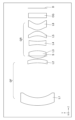
- Fig. 2 is a cross-sectional view taken along the optical axis in the X direction showing an example of the optical configuration of the projection optical system according to the embodiment 1.
- Fig. 3 is a cross-sectional view taken along the optical axis in the Y direction showing an example of the optical configuration of the projection optical system according to the embodiment 1.
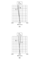
- FIG. 4 shows (A) the field curvature in the X direction and (B) the field curvature in the Y direction when the projection optical system of Example 1 is focused.
- the field curvature is shown as a numerical value at a wavelength of 550 nm.
- S indicates the sagittal image surface
- T indicates the tangential image surface
- X and Y in the diagram indicate the image height.
- the symbols in the aberration diagram are the same in the examples described later.
- the projection optical system of Example 1 is an optical system with a two-group configuration, consisting of, in order from the projection surface side, a front group GF that converts the aspect ratio of the projected image on the projection surface, and a rear group GR that has an image-forming function, as shown in Figures 2 and 3.
- An aperture stop S is also disposed between the front group GF and the rear group GR.
- the front group GF consists of a first lens L1 that has negative power in the X-axis direction and positive power in the Y-axis direction, and a second lens L2 that has negative power in the X-axis direction and negative power in the Y-axis direction.
- the surface shape of the first lens L1 and the second lens L2 on the projection surface side is a rotationally symmetric aspheric shape, and the surface shape of the first lens L1 and the second lens L2 on the image display element side is a toroidal surface.
- the rear group GR is made up of four lenses, the third lens L3 to the sixth lens L6, and has an imaging effect as a whole.
- the third lens L3 to the sixth lens L6 are each a rotationally symmetric aspheric plastic lens.
- the surface data for the projection optical system in Example 1 is shown below (unit: mm).
- Fig. 5 is a cross-sectional view taken along the optical axis in the X direction showing an example of the optical configuration of the projection optical system according to the second embodiment.
- Fig. 6 is a cross-sectional view taken along the optical axis in the Y direction showing an example of the optical configuration of the projection optical system according to the second embodiment.
- FIG. 7 shows (A) the field curvature in the X direction and (B) the field curvature in the Y direction when the projection optical system of Example 2 is focused.
- the field curvature is shown as a numerical value at a wavelength of 550 nm.
- the projection optical system of Example 2 is an optical system with a two-group configuration, consisting of, in order from the projection surface side, a front group GF that converts the aspect ratio of the projected image on the projection surface, and a rear group GR that has an image-forming function, as shown in Figures 5 and 6.
- An aperture stop S is also disposed between the front group GF and the rear group GR.
- the configurations of the front group GF and the rear group GR are the same as those of the projection optical system in Example 1, so a detailed explanation will be omitted.
- Fig. 8 is a cross-sectional view taken along the optical axis in the X direction showing an example of the optical configuration of the projection optical system according to Example 3.
- Fig. 9 is a cross-sectional view taken along the optical axis in the Y direction showing an example of the optical configuration of the projection optical system according to Example 3.
- FIG. 10 shows (A) the field curvature in the X direction and (B) the field curvature in the Y direction when the projection optical system of Example 3 is focused.
- the field curvature is shown as a value at a wavelength of 550 nm.
- the projection optical system of Example 3 is an optical system with a two-group configuration, consisting of, in order from the projection surface side, a front group GF that converts the aspect ratio of the projected image on the projection surface, and a rear group GR that has an image-forming function, as shown in Figures 8 and 9.
- An aperture stop S is also disposed between the front group GF and the rear group GR.
- the configurations of the front group GF and the rear group GR are the same as those of the projection optical system in Example 1, so a detailed explanation will be omitted.
- FIG. 11 is a cross-sectional view taken along the optical axis in the X direction, showing an example of the optical configuration of a projection optical system according to Example 4.
- FIG. 12 is a cross-sectional view taken along the optical axis in the Y direction, showing an example of the optical configuration of a projection optical system according to Example 4.
- FIG. 13 is a diagram showing (A) the field curvature in the X direction and (B) the field curvature in the Y direction when the projection optical system of Example 4 is focused.
- the field curvature is shown as a numerical value at a wavelength of 550 nm.
- the projection optical system of Example 4 is an optical system with a two-group configuration, consisting of, in order from the projection surface side, a front group GF that converts the aspect ratio of the projected image on the projection surface, and a rear group GR that has an image-forming function, as shown in Figures 11 and 12.
- An aperture stop S is also disposed between the front group GF and the rear group GR.
- the configurations of the front group GF and the rear group GR are the same as those of the projection optical system in Example 1, so a detailed explanation will be omitted.
- Fig. 14 is a cross-sectional view taken along the optical axis in the X direction showing an example of the optical configuration of the projection optical system according to Example 5.
- Fig. 15 is a cross-sectional view taken along the optical axis in the Y direction showing an example of the optical configuration of the projection optical system according to Example 5.
- FIG. 16 shows (A) the field curvature in the X direction and (B) the field curvature in the Y direction when the projection optical system of Example 5 is focused.
- the field curvature is shown as a numerical value at a wavelength of 550 nm.
- the projection optical system of Example 5 is an optical system with a two-group configuration, consisting of, in order from the projection surface side, a front group GF that converts the aspect ratio of the projected image on the projection surface, and a rear group GR that has an image-forming function, as shown in Figures 14 and 15.
- An aperture stop S is also disposed between the front group GF and the rear group GR.
- the configurations of the front group GF and the rear group GR are the same as those of the projection optical system in Example 1, so a detailed explanation will be omitted.
- Fig. 17 is a cross-sectional view taken along the optical axis in the X direction showing an example of the optical configuration of the projection optical system according to Example 6.
- Fig. 18 is a cross-sectional view taken along the optical axis in the Y direction showing an example of the optical configuration of the projection optical system according to Example 6.
- FIG. 19 shows (A) the field curvature in the X direction and (B) the field curvature in the Y direction when the projection optical system of Example 6 is focused.
- the field curvature is shown as a numerical value at a wavelength of 550 nm.
- S indicates the sagittal image surface
- T indicates the tangential image surface
- X and Y in the diagram indicate the image height.
- the symbols in the aberration diagram are the same in the examples described later.
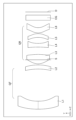
- the projection optical system of Example 6 is an optical system with a two-group configuration, consisting of, in order from the projection surface side, a front group GF that converts the aspect ratio of the projected image on the projection surface, and a rear group GR that has an imaging function, as shown in Figures 17 and 18.
- An aperture stop S is also disposed between the front group GF and the rear group GR.
- the front group GF consists of a first lens L1 that has negative power in the X-axis direction and positive power in the Y-axis direction, and a second lens L2 that has positive power in the X-axis direction and negative power in the Y-axis direction, with its concave surface facing the projection surface.
- the surface shape of the first lens L1 and the second lens L2 on the projection surface side is a rotationally symmetric aspheric shape, and the surface shape of the first lens L1 and the second lens L2 on the image display element side is a toroidal surface.
- the rear group GR is made up of four lenses, the third lens L3 to the sixth lens L6, and has an imaging effect as a whole.
- the third lens L3 to the sixth lens L6 are each a rotationally symmetric aspheric plastic lens.
- the surface data for the projection optical system of Example 6 is shown below (unit: mm).
- Fig. 20 is a cross-sectional view taken along the optical axis in the X direction showing an example of the optical configuration of the projection optical system according to Example 7.
- Fig. 21 is a cross-sectional view taken along the optical axis in the Y direction showing an example of the optical configuration of the projection optical system according to Example 7.
- FIG. 22 shows (A) the field curvature in the X direction and (B) the field curvature in the Y direction when the projection optical system of Example 7 is focused.
- the field curvature is shown as a numerical value at a wavelength of 550 nm.
- the projection optical system of Example 7 is an optical system with a two-group configuration, consisting of, in order from the projection surface side, a front group GF that converts the aspect ratio of the projected image on the projection surface, and a rear group GR that has an image-forming function, as shown in Figures 20 and 21.
- An aperture stop S is also disposed between the front group GF and the rear group GR.
- the configurations of the front group GF and the rear group GR are the same as those of the projection optical system in Example 1, so a detailed explanation will be omitted.
- Fig. 23 is a cross-sectional view taken along the optical axis in the X direction showing an example of the optical configuration of the projection optical system according to Example 8.
- Fig. 24 is a cross-sectional view taken along the optical axis in the Y direction showing an example of the optical configuration of the projection optical system according to Example 8.
- FIG. 25 shows (A) the field curvature in the X direction and (B) the field curvature in the Y direction when the projection optical system of Example 8 is focused.
- the field curvature is shown as a numerical value at a wavelength of 550 nm.
- the projection optical system of Example 8 is an optical system with a two-group configuration, consisting of, in order from the projection surface side, a front group GF that converts the aspect ratio of the projected image on the projection surface, and a rear group GR that has an image-forming function, as shown in Figures 23 and 24.
- An aperture stop S is also disposed between the front group GF and the rear group GR.
- the configurations of the front group GF and the rear group GR are the same as those of the projection optical system in Example 1, so a detailed explanation will be omitted.
Landscapes
- Physics & Mathematics (AREA)
- General Physics & Mathematics (AREA)
- Optics & Photonics (AREA)
- Lenses (AREA)
Priority Applications (2)
| Application Number | Priority Date | Filing Date | Title |
|---|---|---|---|
| PCT/JP2022/037323 WO2024075228A1 (ja) | 2022-10-05 | 2022-10-05 | 投射光学系 |
| JP2024555539A JP7828112B2 (ja) | 2022-10-05 | 2022-10-05 | 投射光学系 |
Applications Claiming Priority (1)
| Application Number | Priority Date | Filing Date | Title |
|---|---|---|---|
| PCT/JP2022/037323 WO2024075228A1 (ja) | 2022-10-05 | 2022-10-05 | 投射光学系 |
Publications (1)
| Publication Number | Publication Date |
|---|---|
| WO2024075228A1 true WO2024075228A1 (ja) | 2024-04-11 |
Family
ID=90607867
Family Applications (1)
| Application Number | Title | Priority Date | Filing Date |
|---|---|---|---|
| PCT/JP2022/037323 Ceased WO2024075228A1 (ja) | 2022-10-05 | 2022-10-05 | 投射光学系 |
Country Status (2)
| Country | Link |
|---|---|
| JP (1) | JP7828112B2 (https=) |
| WO (1) | WO2024075228A1 (https=) |
Citations (7)
| Publication number | Priority date | Publication date | Assignee | Title |
|---|---|---|---|---|
| JPH0345586U (https=) * | 1989-09-13 | 1991-04-26 | ||
| JP2004037977A (ja) * | 2002-07-05 | 2004-02-05 | Minolta Co Ltd | 投影光学系 |
| JP2009300526A (ja) * | 2008-06-10 | 2009-12-24 | Konica Minolta Opto Inc | アナモフィックコンバータおよび画像投影システム |
| JP2010181675A (ja) * | 2009-02-06 | 2010-08-19 | Seiko Epson Corp | プロジェクター |
| JP2016114644A (ja) * | 2014-12-11 | 2016-06-23 | コニカミノルタ株式会社 | 撮像装置及び光学システム |
| JP3223047U (ja) * | 2018-11-06 | 2019-09-12 | 佳能企業股▲分▼有限公司 | 光学レンズ |
| JP2022160329A (ja) * | 2021-04-06 | 2022-10-19 | 日精テクノロジー株式会社 | 投射光学系 |
-
2022
- 2022-10-05 WO PCT/JP2022/037323 patent/WO2024075228A1/ja not_active Ceased
- 2022-10-05 JP JP2024555539A patent/JP7828112B2/ja active Active
Patent Citations (7)
| Publication number | Priority date | Publication date | Assignee | Title |
|---|---|---|---|---|
| JPH0345586U (https=) * | 1989-09-13 | 1991-04-26 | ||
| JP2004037977A (ja) * | 2002-07-05 | 2004-02-05 | Minolta Co Ltd | 投影光学系 |
| JP2009300526A (ja) * | 2008-06-10 | 2009-12-24 | Konica Minolta Opto Inc | アナモフィックコンバータおよび画像投影システム |
| JP2010181675A (ja) * | 2009-02-06 | 2010-08-19 | Seiko Epson Corp | プロジェクター |
| JP2016114644A (ja) * | 2014-12-11 | 2016-06-23 | コニカミノルタ株式会社 | 撮像装置及び光学システム |
| JP3223047U (ja) * | 2018-11-06 | 2019-09-12 | 佳能企業股▲分▼有限公司 | 光学レンズ |
| JP2022160329A (ja) * | 2021-04-06 | 2022-10-19 | 日精テクノロジー株式会社 | 投射光学系 |
Also Published As
| Publication number | Publication date |
|---|---|
| JPWO2024075228A1 (https=) | 2024-04-11 |
| JP7828112B2 (ja) | 2026-03-11 |
Similar Documents
| Publication | Publication Date | Title |
|---|---|---|
| CN104049339B (zh) | 投影光学系统与投影仪设备 | |
| US6779897B2 (en) | Rear projection optical system | |
| JP5042708B2 (ja) | 投写レンズおよびこれを用いた投写型表示装置 | |
| US8320048B2 (en) | Projection lens and projection-type display apparatus using the lens | |
| JP4232269B2 (ja) | 投影光学系 | |
| US8213091B2 (en) | Wide-angle projection zoom lens and projection display device | |
| US9541743B2 (en) | Projection zoom lens and projection type display device | |
| US8508855B2 (en) | Projection lens and projection-type display apparatus using the lens | |
| US7965449B2 (en) | Projection lens system and projection type display apparatus using the same | |
| US7663806B2 (en) | Projection lens and projection type display device using the same | |
| US9557538B2 (en) | Projection zoom lens and projection type display device | |
| JP2012002906A (ja) | 投影レンズ及び投影装置 | |
| US11409191B2 (en) | Projection optical system and projection apparatus | |
| JP4823641B2 (ja) | 投写レンズおよびこれを用いた投写型表示装置 | |
| JP5026929B2 (ja) | 投射用レンズおよび投射型画像表示装置 | |
| US20150247997A1 (en) | Projection zoom lens and projection type display device | |
| JP4340469B2 (ja) | 投射用レンズおよび投射型画像表示装置 | |
| JP2007034082A (ja) | 投写レンズおよびこれを用いた投写型表示装置 | |
| JP2007079107A (ja) | 2群ズーム投影レンズおよび投写型表示装置 | |
| JP4739810B2 (ja) | 投射用レンズおよびプロジェクタ装置 | |
| JP2022160329A (ja) | 投射光学系 | |
| JP2008309991A (ja) | 投写レンズおよびこれを用いた投写型表示装置 | |
| JP2004252084A (ja) | 投射用ズームレンズおよび拡大投射装置 | |
| JP4340468B2 (ja) | 投射用レンズおよび投射型画像表示装置 | |
| JP7828112B2 (ja) | 投射光学系 |
Legal Events
| Date | Code | Title | Description |
|---|---|---|---|
| 121 | Ep: the epo has been informed by wipo that ep was designated in this application |
Ref document number: 22961415 Country of ref document: EP Kind code of ref document: A1 |
|
| NENP | Non-entry into the national phase |
Ref country code: DE |
|
| ENP | Entry into the national phase |
Ref document number: 2024555539 Country of ref document: JP Kind code of ref document: A |
|
| WWE | Wipo information: entry into national phase |
Ref document number: 2024555539 Country of ref document: JP |
|
| 122 | Ep: pct application non-entry in european phase |
Ref document number: 22961415 Country of ref document: EP Kind code of ref document: A1 |