WO2024071017A1 - 鉛蓄電池 - Google Patents
鉛蓄電池 Download PDFInfo
- Publication number
- WO2024071017A1 WO2024071017A1 PCT/JP2023/034670 JP2023034670W WO2024071017A1 WO 2024071017 A1 WO2024071017 A1 WO 2024071017A1 JP 2023034670 W JP2023034670 W JP 2023034670W WO 2024071017 A1 WO2024071017 A1 WO 2024071017A1
- Authority
- WO
- WIPO (PCT)
- Prior art keywords
- lead
- negative electrode
- plate
- negative
- acid battery
- Prior art date
- Legal status (The legal status is an assumption and is not a legal conclusion. Google has not performed a legal analysis and makes no representation as to the accuracy of the status listed.)
- Ceased
Links
Images
Classifications
-
- H—ELECTRICITY
- H01—ELECTRIC ELEMENTS
- H01M—PROCESSES OR MEANS, e.g. BATTERIES, FOR THE DIRECT CONVERSION OF CHEMICAL ENERGY INTO ELECTRICAL ENERGY
- H01M4/00—Electrodes
- H01M4/02—Electrodes composed of, or comprising, active material
- H01M4/14—Electrodes for lead-acid accumulators
-
- H—ELECTRICITY
- H01—ELECTRIC ELEMENTS
- H01M—PROCESSES OR MEANS, e.g. BATTERIES, FOR THE DIRECT CONVERSION OF CHEMICAL ENERGY INTO ELECTRICAL ENERGY
- H01M10/00—Secondary cells; Manufacture thereof
- H01M10/06—Lead-acid accumulators
- H01M10/12—Construction or manufacture
-
- H—ELECTRICITY
- H01—ELECTRIC ELEMENTS
- H01M—PROCESSES OR MEANS, e.g. BATTERIES, FOR THE DIRECT CONVERSION OF CHEMICAL ENERGY INTO ELECTRICAL ENERGY
- H01M4/00—Electrodes
- H01M4/02—Electrodes composed of, or comprising, active material
- H01M4/36—Selection of substances as active materials, active masses, active liquids
- H01M4/48—Selection of substances as active materials, active masses, active liquids of inorganic oxides or hydroxides
- H01M4/56—Selection of substances as active materials, active masses, active liquids of inorganic oxides or hydroxides of lead
-
- H—ELECTRICITY
- H01—ELECTRIC ELEMENTS
- H01M—PROCESSES OR MEANS, e.g. BATTERIES, FOR THE DIRECT CONVERSION OF CHEMICAL ENERGY INTO ELECTRICAL ENERGY
- H01M50/00—Constructional details or processes of manufacture of the non-active parts of electrochemical cells other than fuel cells, e.g. hybrid cells
- H01M50/40—Separators; Membranes; Diaphragms; Spacing elements inside cells
- H01M50/409—Separators, membranes or diaphragms characterised by the material
- H01M50/411—Organic material
- H01M50/414—Synthetic resins, e.g. thermoplastics or thermosetting resins
- H01M50/417—Polyolefins
-
- H—ELECTRICITY
- H01—ELECTRIC ELEMENTS
- H01M—PROCESSES OR MEANS, e.g. BATTERIES, FOR THE DIRECT CONVERSION OF CHEMICAL ENERGY INTO ELECTRICAL ENERGY
- H01M50/00—Constructional details or processes of manufacture of the non-active parts of electrochemical cells other than fuel cells, e.g. hybrid cells
- H01M50/40—Separators; Membranes; Diaphragms; Spacing elements inside cells
- H01M50/409—Separators, membranes or diaphragms characterised by the material
- H01M50/449—Separators, membranes or diaphragms characterised by the material having a layered structure
- H01M50/451—Separators, membranes or diaphragms characterised by the material having a layered structure comprising layers of only organic material and layers containing inorganic material
-
- H—ELECTRICITY
- H01—ELECTRIC ELEMENTS
- H01M—PROCESSES OR MEANS, e.g. BATTERIES, FOR THE DIRECT CONVERSION OF CHEMICAL ENERGY INTO ELECTRICAL ENERGY
- H01M2220/00—Batteries for particular applications
- H01M2220/20—Batteries in motive systems, e.g. vehicle, ship, plane
-
- H—ELECTRICITY
- H01—ELECTRIC ELEMENTS
- H01M—PROCESSES OR MEANS, e.g. BATTERIES, FOR THE DIRECT CONVERSION OF CHEMICAL ENERGY INTO ELECTRICAL ENERGY
- H01M50/00—Constructional details or processes of manufacture of the non-active parts of electrochemical cells other than fuel cells, e.g. hybrid cells
- H01M50/40—Separators; Membranes; Diaphragms; Spacing elements inside cells
- H01M50/409—Separators, membranes or diaphragms characterised by the material
- H01M50/446—Composite material consisting of a mixture of organic and inorganic materials
-
- Y—GENERAL TAGGING OF NEW TECHNOLOGICAL DEVELOPMENTS; GENERAL TAGGING OF CROSS-SECTIONAL TECHNOLOGIES SPANNING OVER SEVERAL SECTIONS OF THE IPC; TECHNICAL SUBJECTS COVERED BY FORMER USPC CROSS-REFERENCE ART COLLECTIONS [XRACs] AND DIGESTS
- Y02—TECHNOLOGIES OR APPLICATIONS FOR MITIGATION OR ADAPTATION AGAINST CLIMATE CHANGE
- Y02E—REDUCTION OF GREENHOUSE GAS [GHG] EMISSIONS, RELATED TO ENERGY GENERATION, TRANSMISSION OR DISTRIBUTION
- Y02E60/00—Enabling technologies; Technologies with a potential or indirect contribution to GHG emissions mitigation
- Y02E60/10—Energy storage using batteries
Definitions
- the present invention relates to a lead-acid battery.
- Lead-acid batteries are used in vehicles, industrial applications, and a variety of other applications.
- Lead-acid batteries contain positive and negative electrode plates, a separator between them, and an electrolyte. Separators for lead-acid batteries are required to have a variety of performance characteristics.
- Patent Document 1 proposes "a lead-acid battery separator, the lead-acid battery separator comprising a porous membrane and/or a fibrous mat, and one or more conductive elements or nucleating additives within or on the porous membrane and/or the fibrous mat.”
- Patent document 2 proposes "a lead-acid battery separator comprising a porous membrane or substrate having at least one electrically non-conductive, conductive, or semiconductive layer, film, coating, deposition, or material comprising at least one of particles, fibers, or materials, the particles, fibers, or materials comprising at least one of silica, silicon oxide, alumina, aluminum oxide, and combinations, blends, or mixtures thereof.”
- Patent Document 3 proposes a lead-acid battery comprising "a plate group in which positive plates having a positive electrode active material containing lead dioxide and negative plates having a negative electrode active material containing metallic lead are alternately stacked with separators interposed therebetween, the plate group is immersed in an electrolyte to form a cell, the flatness of the positive plate after chemical formation is 4.0 mm or less, and the bismuth content in the negative electrode active material is 0.5 ppm or more and 250 ppm or less.”
- Patent Document 4 proposes "a lead-acid battery comprising a negative plate made of a negative electrode grid that does not contain Sb, a positive plate made of a positive electrode grid that does not contain Sb and having a layer containing 0.01 to 0.20 wt % of Sb based on the amount of the positive electrode active material on at least a portion of the surface that comes into contact with the positive electrode active material, and a separator inserted between the positive and negative plates, the entire plate surfaces of the positive and negative plates being immersed in an electrolyte, and the negative electrode active material containing 0.02 to 0.10 wt % of Bi based on the amount of the negative electrode active material.”
- Patent Document 5 proposes a lead-acid battery comprising a negative electrode plate having a non-Sb-based negative electrode grid and a negative electrode active material containing 0.1 to 3 weight percent Ba and 0.1 to 2.5 weight percent graphite or carbon, the negative electrode active material containing at least one member selected from the group consisting of Sb, Sn, Bi, Zn, Se, Mn, Ca, Mg, and Sr.
- JP 2020-533741 A JP 2018-530125 A JP 2021-163612 A JP 2006-079973 A JP 2003-142085 A
- Recent lead-acid batteries are used under different conditions than previous general starter lead-acid batteries.
- Such lead-acid batteries are used, for example, in a partial state of charge (PSOC). If the lead-acid battery continues to discharge without being charged from the PSOC while the engine is stopped, the depth of discharge (hereinafter referred to as "DOD") becomes deep.
- PSOC partial state of charge
- DOD depth of discharge
- the electrical load of electrical equipment and communication devices installed in vehicles has increased, and the discharge capacity from lead-acid batteries has also increased.
- the conditions for charge-discharge cycle tests are becoming stricter than before. For example, there is a strong demand for improving the lifespan in charge-discharge cycle tests in which the battery is discharged to 17.5% DOD.
- One of the factors that cause deterioration of lead-acid batteries when used at deep DOD is a decrease in the charge acceptance of the negative electrode material and an increase in impedance due to a high resistance layer that forms at the interface between the positive electrode material and the positive electrode grid.
- a lead-acid battery comprising a positive electrode plate, a negative electrode plate, a separator interposed between the positive electrode plate and the negative electrode plate, and an electrolyte
- the positive electrode plate including a positive electrode material
- the negative electrode plate including a negative electrode material
- the negative electrode material including a Bi element
- the content of the Bi element in the negative electrode material being 100 ppm or more and 300 ppm or less by mass
- the separator including a resin substrate, and having a conductive layer between the negative electrode plate and the resin substrate.
- This disclosure improves the life performance of lead-acid batteries used in deep DOD.
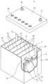
- FIG. 1 is a partially cutaway perspective view showing the appearance and internal structure of a lead-acid battery according to one embodiment of the present invention
- the embodiments of the present disclosure are described using examples, but the present disclosure is not limited to the examples described below.
- specific numerical values and materials may be exemplified, but other numerical values and materials may be applied as long as the effects of the present disclosure are obtained.
- the expression "numerical value A to numerical value B" includes numerical value A and numerical value B and can be read as "numerical value A or more and numerical value B or less.”
- any of the exemplified lower limits and any of the exemplified upper limits can be arbitrarily combined as long as the lower limit is not equal to or greater than the upper limit.
- one of the materials may be selected and used alone, or two or more of the materials may be used in combination.
- the up-down direction of a lead-acid battery or the components of a lead-acid battery refers to the up-down direction in the vertical direction of the lead-acid battery arranged in a state of use.
- Each electrode plate, the positive electrode plate and the negative electrode plate has a lug portion for connecting to an external terminal.
- the lug portion is provided on the top of the electrode plate so as to protrude upward.
- the lead-acid battery according to the present disclosure may be a valve-regulated battery (VRLA type battery), but a flooded battery (vented type battery) is preferred since it can effectively utilize the effects of the Bi element.
- a lead-acid battery comprises positive and negative plates, a separator interposed between the positive and negative plates, and an electrolyte.
- the electrolyte contains sulfuric acid. Charging and discharging proceeds as sulfate ions move between the positive and negative plates and the electrolyte. During discharging, sulfate ions move to the positive and negative plates, decreasing the density of the electrolyte. During charging, sulfate ions move from the positive and negative plates into the electrolyte, increasing the density of the electrolyte.
- the positive and negative plates and the separator constitute a plate group.
- the plate group, together with the electrolyte, constitutes a cell.
- One plate group constitutes one cell.
- a lead-acid battery comprises one or more electrode groups, and thus one or more cells. There is no particular limit to the number of positive and negative plates contained in one plate group.
- the plate group of the lead-acid battery according to the present disclosure includes, for example, a total of 12 or more positive and negative plates.
- the multiple plate groups are usually housed in individual cell chambers and connected in series with each other.
- the positive plate includes a positive electrode material.
- the positive electrode material contains at least lead dioxide during charging and at least lead sulfate during discharging as a positive electrode active material that develops capacity through an oxidation-reduction reaction.
- the negative plate includes a negative electrode material.
- the negative electrode material contains at least lead during charging and at least lead sulfate during discharging as a negative electrode active material that develops capacity through an oxidation-reduction reaction.
- a lead-acid battery includes a positive plate, a negative plate, a separator interposed between the positive plate and the negative plate, and an electrolyte
- the positive plate includes a positive electrode material
- the negative plate includes a negative electrode material
- the negative electrode material includes a Bi element
- the Bi element content in the negative electrode material is 100 ppm or more and 300 ppm or less by mass
- the separator includes a resin substrate and has a conductive layer between the negative plate and the resin substrate.
- the lead-acid battery according to one embodiment of the present invention has excellent life performance even when used at deep DOD.
- the conductive layer may contain a carbon material.
- the lead-acid battery described in (2) above can have a conductive layer that is lightweight, highly conductive, and has excellent ionic conductivity.
- the carbon material electrically connected to the negative electrode plate promotes water electrolysis during charging, making it easier for gas to be generated, which is advantageous in preventing stratification of the electrolyte.
- the carbon material may be at least one selected from the group consisting of carbon black and carbon fiber.
- the lead-acid battery described in (3) above can be lighter, more conductive, and have a thinner conductive layer.
- the conductive layer may have a thickness of 1 ⁇ m or more and 30 ⁇ m or less.
- the thickness of the conductive layer 1 ⁇ m or more by making the thickness of the conductive layer 1 ⁇ m or more, a strong conductive path is formed that spreads across the entire negative plate, and the reaction in the vertical direction of the negative plate is made uniform.
- the thickness of the conductive layer 30 ⁇ m or less an increase in internal resistance can be avoided as much as possible.
- the conductive layer may be disposed on the surface of the resin substrate.
- the conductive layer integrated with the resin substrate provided in the lead-acid battery described in (5) above can be formed in various ways during the separator manufacturing process.
- the ratio of the mass of the positive electrode material to the mass of the negative electrode material may be 1.2 or more and 1.4 or less.
- the lead-acid battery described in (6) above reduces the amount of negative electrode material used, making the lead-acid battery lighter and less expensive. Even in such a case, the charge acceptance is less likely to decrease, and sulfation of the negative plate is less likely to progress.
- the lead-acid battery according to any one of (1) to (6) above may be for use in a vehicle that is controlled by an idle stop-start (ISS). This is because there is a high need to improve the deep discharge cycle life of lead-acid batteries installed in vehicles that are controlled by an ISS.
- ISS idle stop-start
- the negative electrode material according to the present disclosure contains a predetermined amount of Bi (bismuth) element.
- the Bi element has the effect of improving the charge acceptance of the negative electrode material. Such an effect is believed to be due to the effect of the Bi element in reducing hydrogen generation overvoltage, etc.
- the negative plate of a lead-acid battery is discharged to a deep DOD
- the negative plate is likely to undergo uneven reactions in the vertical direction. This is because, during discharge, the negative plate is likely to be discharged relatively uniformly overall, but during charging, it tends to become undercharged depending on the charging conditions (charging voltage, charging time).
- the reaction PbSO 4 + 2e - ⁇ Pb + SO 4 2- and the reaction 2H + + 2e - ⁇ H 2 proceed competitively at the top of the negative plate, reducing the number of electrons that can be supplied to the bottom of the negative plate.
- the top of the negative plate which is easily collected, is selectively charged, and the bottom of the negative plate is difficult to charge.
- lead sulfate is likely to remain at the bottom of the negative plate.
- lead sulfate accumulates at the bottom of the negative plate, promoting uneven reactions in the vertical direction of the negative plate.
- the negative plate contains a certain amount of Bi element
- the upper part of the negative plate is easier to charge due to improved charge acceptance caused by the Bi element's effect of reducing hydrogen generation overvoltage.
- the effect of adding Bi element on improving charge acceptance is limited, and the unevenness of the reaction in the vertical direction of the negative plate becomes more noticeable when Bi element is added.
- the unevenness of the reaction in the vertical direction of the negative plate is significantly suppressed.
- the conductive layer is thought to provide the negative plate with an auxiliary conductive path that extends across the entire negative plate. As a result, the charging current is distributed more evenly across the entire negative plate.
- Bi in the negative electrode material has the effect of promoting gas generation during charging by reducing hydrogen generation overvoltage.
- a moderate amount of gas is generated, which causes the electrolyte to flow.
- the charging reaction and gas generation reaction in the negative electrode material below the negative plate are promoted by distributing the charging current to the entire negative plate by the conductive layer.
- the gas generated in the gas generation reaction promotes the flow of the electrolyte near the bottom of the negative plate, allowing the charge and discharge reactions to proceed more uniformly across the entire negative plate.
- the positive plate which is arranged opposite the negative plate, is affected by the charge/discharge reaction of the negative plate.
- the reaction When the upper part of the negative plate is selectively charged and the reaction becomes uneven in the vertical direction of the negative plate, the reaction also becomes uneven in the vertical direction of the positive plate.
- the charge/discharge reaction proceeds more uniformly across the entire negative plate, the charge/discharge reaction also proceeds more uniformly across the entire positive plate. As a result, the increase in impedance due to deterioration of the positive plate is suppressed.
- the content of Bi element in the negative electrode material must be limited to 100 ppm or more and 300 ppm or less by mass. If the content of Bi element is less than 100 ppm by mass, the charging current tends to decay rapidly when the lead-acid battery approaches a fully charged state during constant voltage charging. In other words, the effect of the Bi element in improving the charge acceptance of the negative electrode material is not fully obtained.
- the deep discharge cycle test is a condition that makes it difficult to secure the amount of charging electricity in the first place. Therefore, in the end, the upper part of the negative plate, which is easily collected, is selectively charged, and the lower part of the negative plate is difficult to charge.
- the content of Bi element in the negative electrode material is preferably 100 ppm or more and 250 ppm or less by mass, and may be 150 ppm or more and 230 ppm or less.
- the conductive layer may be interposed between the negative plate and the resin substrate of the separator.
- the conductive layer comes into contact with the negative plate at any time to provide the negative plate with an auxiliary conductive path.
- the conductive layer may be an independent member separate from the negative plate and the resin substrate of the separator, may be integrated with the negative plate, or may be integrated with the resin substrate of the separator.
- the separator may be composed of only the resin substrate, may be composed of the resin substrate and the conductive layer, or may further have other components.
- the separator and the resin substrate may be synonymous in some cases.
- the independent conductive layer only needs to have ionic conductivity, but is preferably porous in order to prevent an increase in internal resistance as much as possible.
- the independent conductive layer may be, for example, a woven or nonwoven fabric made of conductive fibers, and specifically, carbon paper, carbon cloth, etc. may be used.
- the conductive layer integrated with the negative plate can be formed by forming a conductive layer on an unformed negative plate, then aging and drying it. Conductive particles can be applied to the surface of the negative plate by a method such as spray coating either before or after formation.
- the conductive layer integrated with the resin substrate of the separator can be formed by various methods during the separator manufacturing process.
- the conductive layer may be a composite layer of at least a portion of the separator's constituent materials and a conductive material.
- the conductive material constituting the composite layer may be conductive fibers, conductive particles, etc.
- the conductive layer in either form may contain a carbon material.
- Carbon materials are lightweight, highly conductive, and suitable for forming a porous structure to ensure excellent ionic conductivity.
- the electrolysis of water is promoted during charging, starting from the carbon material electrically connected to the negative plate, and gas is more likely to be generated.
- the generated gas stirs the electrolyte.
- stratification of the electrolyte is suppressed not only by the driving force of the Bi element for the flow of the electrolyte, but also by the conductive layer. Therefore, the synergistic effect of suppressing stratification and distributing the charging current to the entire negative plate becomes significant.
- Examples of the carbon material constituting the conductive layer include graphite, activated carbon, carbon black, carbon fiber, and carbon nanotubes. These carbon materials are conductive.
- the carbon material may be at least one selected from the group consisting of carbon black and carbon fiber.
- the carbon black may be acetylene black, ketjen black, thermal black, channel black, furnace black, lamp black, high surface area carbon black, and the like.
- the carbon fiber may be carbon nanofiber, carbon nanotubes, and the like.
- the thickness of the conductive layer is, for example, 1 ⁇ m or more, 2 ⁇ m or more, 5 ⁇ m or more, 10 ⁇ m or more, or 15 ⁇ m or more.
- the thickness of the conductive layer is, for example, 40 ⁇ m or less, 30 ⁇ m or less, 25 ⁇ m or less, or 20 ⁇ m or less. The thicker the conductive layer, the stronger the auxiliary conductive path that spreads across the entire negative plate, and the more uniform the reaction in the vertical direction of the negative plate. Furthermore, by making the thickness of the conductive layer 40 ⁇ m or less, it is possible to suppress an increase in the inter-electrode distance and to avoid an increase in internal resistance as much as possible.
- the thickness of the conductive layer is determined by measuring the thickness at five randomly selected points on a cross-sectional photograph of the conductive layer and averaging the measurements.
- the conductive layer preferably faces, for example, 80% or more of the area of the main surface of the negative plate so that the charging current is distributed to the entire negative plate as much as possible through the auxiliary conductive path.
- the area of the main surface of the negative plate is the area enclosed by the outline of the orthogonal projection image when the main surface is viewed from the normal direction.
- the ratio of the mass of the positive electrode material to the mass of the negative electrode material (hereinafter also referred to as the "Mp/Mn ratio") is, for example, 1.2 to 1.4, and may be 1.3 to 1.4.
- the mass of the positive electrode material is the mass of the positive electrode material contained in one positive plate.
- the mass of the negative electrode material is the mass of the negative electrode material contained in one negative plate.
- Increasing the Mp/Mn ratio to 1.2 to 1.4 means reducing the amount of negative electrode material used. In other words, by making the Mp/Mn ratio 1.2 to 1.4, the weight and cost of the lead-acid battery can be reduced.
- the Mp/Mn ratio is 1.2 or more and 1.4 or less, the load on the negative plate becomes considerably large and the charge acceptance is likely to decrease. If the negative electrode material contains a certain amount of Bi element and has a conductive layer between the negative plate and the separator, the charge reaction proceeds more uniformly throughout the negative plate, so that even if the Mp/Mn ratio is increased to 1.2 or more and 1.4 or less, the charge acceptance is not likely to decrease and sulfation of the negative plate is also not likely to progress.
- the lead-acid battery disclosed herein is suitable for use in vehicles that are controlled by idling stop-start (ISS).
- Lead-acid batteries installed in vehicles that are controlled by ISS are often used in PSOC, and are required to have excellent life performance in deep discharge cycles in which the battery is discharged to a deep DOD.
- pressure is easily applied to the electrode plate group in the stacking direction, and the electrode plate group is easily attached to the conductive layer interposed between the negative electrode plate and the separator. In this case, the charge/discharge reaction is more likely to be uniform throughout the negative electrode plate.
- gas generated in the negative electrode plate can move upward through the gaps in the electrolyte after passing through the conductive layer and the resin substrate. This allows the electrolyte impregnated in the separator or resin substrate to be agitated, further enhancing the effect of suppressing stratification.
- the positive electrode plate includes a positive current collector and a positive electrode material.
- the positive electrode material is held by the positive current collector.
- the positive electrode material is the portion of the positive electrode plate excluding the positive current collector.
- An attachment member such as a conductive layer, a mat, or pasting paper may be attached to the positive electrode plate.
- the attachment member is used integrally with the positive electrode plate, and is therefore included as a component of the positive electrode plate.
- the positive electrode material is the portion of the positive electrode plate excluding the positive current collector and the attachment member.
- the positive electrode collector may be formed by casting lead (Pb) or a lead alloy, or by processing a lead or lead alloy sheet.
- the processing method may be, for example, an expanding process or a punching process. If a lattice-shaped collector is used as the positive electrode collector, it is easy to support the positive electrode material.
- the lead alloy used for the positive electrode current collector is preferably a Pb-Ca alloy or a Pb-Ca-Sn alloy, which has excellent corrosion resistance and mechanical strength.
- the positive electrode current collector may have metal layers with different compositions, and the metal layer may be a single layer or multiple layers.
- the positive electrode material includes a positive electrode active material that develops capacity through an oxidation-reduction reaction.
- the positive electrode active material includes lead dioxide, lead sulfate, and the like.
- the positive electrode material may include additives as necessary.
- the additives may include reinforcing materials, antimony compounds, and the like. Examples of reinforcing materials include inorganic fibers and organic fibers.
- An unformed positive electrode plate is obtained by maturing and drying a positive electrode paste filled in a positive electrode current collector and a positive electrode current collector.
- the positive electrode paste is prepared by kneading a mixture containing lead powder, water, and sulfuric acid.
- the positive electrode paste may contain additives as necessary.
- the additives may include reinforcing materials, antimony compounds, etc.
- Such a positive electrode plate is also called a paste type positive electrode plate.
- the positive plate can be obtained by chemically forming an unformed positive plate. Chemical formation can be performed by immersing a group of plates including the unformed positive plate in an electrolyte containing sulfuric acid in a lead-acid battery container and charging the group of plates. Chemical formation can also be performed before assembling the lead-acid battery or the group of plates.
- the negative electrode plate includes a negative current collector and a negative electrode material.
- the negative electrode material is held by the negative current collector.
- the negative electrode material is the portion of the negative electrode plate excluding the negative current collector.
- An attachment member such as a conductive layer, a mat, or pasting paper may be attached to the negative electrode plate.
- the attachment member is included in the components of the negative electrode plate.
- the negative electrode material is the portion of the negative electrode plate excluding the negative current collector and the attachment member.
- the negative electrode current collector may be formed by casting lead (Pb) or a lead alloy, or by processing a lead or lead alloy sheet.
- the processing method may be an expanding process or a punching process. If a lattice-shaped current collector is used as the negative electrode current collector, it is easy to support the negative electrode material.
- At least one of the positive electrode collector and the negative electrode collector may be formed by expanding or punching. Plates using collectors (expanded grids) formed by expanding are prone to deformation at the corners due to interference with the manufacturing equipment during the manufacturing process. The corners of such plates are prone to short circuits that break through the separator.
- the separator according to the present disclosure may have a conductive layer, and therefore is relatively strong and is also excellent in that it can suppress such short circuits.
- the lead alloy used in the negative electrode current collector may be any of Pb-Sb alloy, Pb-Ca alloy, and Pb-Ca-Sn alloy.
- the lead alloy used in the negative electrode current collector may contain at least one element selected from the group consisting of Ba, Ag, Al, Bi, As, Se, Cu, etc. as an additive element.
- the negative electrode current collector may have metal layers with different compositions, and the metal layer may be a single layer or multiple layers.
- the negative electrode material includes a negative electrode active material that develops capacity through an oxidation-reduction reaction.
- the negative electrode active material includes lead, lead sulfate, etc.
- the negative electrode material includes Bi element in an amount of 100 ppm or more and 300 ppm or less by mass.
- the negative electrode material may include other additives as necessary.
- the additives may include an organic shrinkage inhibitor, a carbonaceous material, barium sulfate, etc.
- ⁇ Analysis of Bi element content> For the analysis of the content of Bi in the negative electrode material, a negative plate taken out from an unused or early-used fully charged lead-acid battery is used. The negative plate taken out from the lead-acid battery is washed and dried prior to analysis or measurement.
- the negative plate removed from the lead-acid battery is washed with water and dried, after which the negative electrode material is extracted and a sample of the pulverized negative electrode material is prepared.
- a solution of nitric acid and water in a volume ratio of 1:3 is heated to approximately 100°C to dissolve the sample. After that, the insoluble matter is filtered out from the solution, and the Bi content is determined by ICP (Inductively Coupled Plasma) emission analysis.
- the fully charged state of a flooded lead-acid battery is defined by the definition of JIS D 5301:2019. More specifically, the fully charged state is defined as a state in which a lead-acid battery is charged with a current 2I 20 (unit: A) that is twice the 20-hour rate current I 20 until the terminal voltage (unit: V) during charging measured every 15 minutes in a water tank at 25°C ⁇ 2 °C or the electrolyte density converted to a temperature of 20°C shows a constant value with three significant digits three consecutive times.
- the 20-hour rate current I 20 is a current (A) that is 1/20 of the Ah value described in the rated capacity.
- the value described as the rated capacity is a value in units of Ah (ampere-hours).
- the unit of the current set based on the value described as the rated capacity is A (ampere).
- the fully charged state is the state in which charging is performed in an air tank at 25°C ⁇ 2°C at a constant current and constant voltage of 2.67 V/cell (16.00 V for a lead-acid battery with a rated voltage of 12 V) at a current 5I20 that is five times the 20-hour rate current I20, and charging is terminated when the total charging time reaches 24 hours.
- a fully charged lead-acid battery is a lead-acid battery that has already been chemically charged to a fully charged state.
- the timing for charging a lead-acid battery to a fully charged state may be immediately after chemical formation, or after a period of time has passed since chemical formation.
- a lead-acid battery that is in use (preferably in the early stages of use) may be charged after chemical formation.
- a battery in its early stages of use is one that has not been in use for very long and has barely deteriorated.
- organic shrinkage inhibitor examples include lignin, lignin sulfonic acid, and synthetic organic shrinkage inhibitors.
- the synthetic organic shrinkage inhibitor may be, for example, a formaldehyde condensate of a phenol compound.
- the organic shrinkage inhibitor may be used alone or in combination of two or more.
- the content of the organic shrinkage inhibitor in the negative electrode material is, for example, 0.01% by mass or more and 1% by mass or less.
- Carbonaceous materials that can be used include carbon black, artificial graphite, natural graphite, hard carbon, and soft carbon.
- the carbonaceous materials may be used alone or in combination of two or more.
- the content of the carbonaceous material in the negative electrode material is, for example, 0.1% by mass or more and 3% by mass or less.
- the barium sulfate content in the negative electrode material is, for example, 0.1% by mass or more and 3% by mass or less.
- An unformed negative electrode plate is obtained by maturing and drying the negative electrode current collector and the negative electrode paste filled in the negative electrode current collector.
- the maturing is preferably performed in an atmosphere that is higher than room temperature and has high humidity.
- the negative electrode paste is prepared by kneading a mixture containing lead powder, water, and sulfuric acid.
- the negative electrode paste may contain additives as necessary.
- the additives may include bismuth compounds (e.g., bismuth sulfate), organic shrinkage inhibitors, carbonaceous materials, barium sulfate, etc.
- a negative plate is obtained by chemically forming an unformed negative plate. Chemical formation may be performed by immersing a plate group including the unformed negative plate in an electrolyte containing sulfuric acid in a lead-acid battery container and charging the plate group. Chemical formation may be performed before assembling the lead-acid battery or the plate group.
- the negative active material in the charged state contains spongy lead.
- the separator includes a resin substrate and a conductive layer disposed on the surface of the resin substrate.
- the conductive layer may be disposed on both of the two main surfaces of the resin substrate, but it is sufficient that the conductive layer is disposed on the main surface on the negative electrode plate side.
- the conductive layer disposed on the surface of the resin substrate preferably contains a carbon material, which is lightweight and highly conductive.
- a carbon material which is lightweight and highly conductive.
- carbon black which has excellent productivity for the separator.
- acetylene black, ketjen black, and high surface area carbon black can be used.
- the carbon material may be at least one selected from the group consisting of carbon black and carbon fiber.
- the carbon material does not necessarily have to cover the main surface of the resin substrate in a layered form.
- the carbon material may be arranged on the main surface of the resin substrate in a non-layered form.
- non-layered forms include a form in which the carbon material is arranged in the form of dispersed islands. Even in such a form, it may be referred to as a coating layer that covers at least a portion of the main surface of the resin substrate.
- a coating layer that covers at least a portion of the main surface of the resin substrate, even if it is not in a layered form is considered to be a conductive layer.
- the thickness of the conductive layer may be 1 ⁇ m or more, or 5 ⁇ m or more.
- the thickness of the conductive layer may be 1 ⁇ m to 40 ⁇ m, 5 ⁇ m to 30 ⁇ m, or 10 ⁇ m to 20 ⁇ m.
- the thickness of the conductive layer may be measured at any five or more points, and the average of the measured values obtained may be calculated.
- the carbon material content in the separator may be, for example, 2% by mass or more, or 3% by mass or more. In this case, the charging current is more likely to be distributed evenly across the entire negative plate.
- the carbon material content in the separator may be 40% by mass or less, or 30% by mass or less.
- Examples of the form of the resin substrate include woven fabric, nonwoven fabric, and porous membrane.
- a porous membrane is preferred from the viewpoints of productivity and cost, and a nonwoven fabric is preferred from the viewpoint of electrolyte retention.
- Materials for the woven fabric, nonwoven fabric, and porous membrane can be appropriately selected from substances commonly used in lead-acid batteries.
- the conductive layer contains a carbon material
- water electrolysis is accelerated, especially toward the end of charging, but oxygen gas is generated at the positive electrode.
- a porous film may be used as the resin substrate, and crystalline and amorphous regions may be formed in the porous film to enhance the crystallinity of the porous film.
- the ratio R represented by A1 /( A1 + A2 ) may be 0.70 or more.
- A1 is the area of the diffraction peak (first diffraction peak) with the highest peak height among the diffraction peaks corresponding to the crystalline region.
- A2 is the area of the diffraction peak (second diffraction peak) with the second highest peak height among the diffraction peaks corresponding to the crystalline region.
- the porous film with the ratio R of 0.70 or more is also referred to as "porous film (F)".
- the area of the diffraction peak is obtained by fitting the diffraction peak due to the crystalline region in the XRD spectrum of the porous film (F).
- the ratio R is obtained from the above formula using the area A1 of the first diffraction peak and the area A2 of the second diffraction peak obtained.
- Porous films can also be impregnated with oil to increase their oxidation resistance.
- oil can increase the resistance of the porous film.
- the ratio R may be 0.75 or more.
- the ratio R may be 0.90 or less, 0.85 or less, or 0.80 or less.
- the porous film (F) contains crystalline regions in which the molecules of the constituent materials are arranged in a relatively regular manner (i.e., highly ordered), and amorphous regions in which the order is low. Therefore, in the XRD spectrum of the porous film (F), diffraction peaks due to the crystalline regions are observed, and scattered light due to the amorphous regions is observed as a halo. By having a ratio R of 0.70 or more, better PSOC life performance is obtained.
- the porous membrane (F) contains a polymer material (hereinafter also referred to as a base polymer).
- the base polymer contains a crystalline polymer.
- the porous membrane (F) contains, for example, a polyolefin.
- a polyolefin is a polymer that contains at least an olefin unit (a monomer unit derived from an olefin).
- the porous film (F) preferably contains a polyolefin, and more preferably contains a polyolefin containing at least ethylene units. In such a porous film (F), the ratio R can be adjusted relatively easily.
- the porous film (F) contains a polyolefin containing at least ethylene units
- the first diffraction peak corresponds to the (110) plane of the crystalline region
- the second diffraction peak corresponds to the (200) plane of the crystalline region.
- the diffraction peak corresponding to the (110) plane of the crystalline region is observed in a 2 ⁇ range of 20° to 22.5°, and the diffraction peak corresponding to the (200) plane of the crystalline region is observed in a 2 ⁇ range of 23° to 24.5°.
- the halo of the amorphous region is observed in a 2 ⁇ range of 17° to 27°.
- polyolefin may be used in combination with another base polymer.
- the ratio of polyolefin to the total base polymer contained in the porous film (F) is, for example, 50% by mass or more, 80% by mass or more, or 90% by mass or more.
- the ratio of polyolefin is, for example, 100% by mass or less.
- the base polymer may be composed of polyolefin only. When the ratio of polyolefin is this high, the oxidation resistance of the porous film (F) tends to be low, but even in such a case, a high life performance can be ensured by setting the ratio R within the above range.
- Polyolefins include, for example, homopolymers of olefins, copolymers containing different olefin units, and copolymers containing olefin units and copolymerizable monomer units.
- Copolymers containing olefin units and copolymerizable monomer units may contain one or more types of olefin units.
- Copolymers containing olefin units and copolymerizable monomer units may contain one or more types of copolymerizable monomer units.
- a copolymerizable monomer unit is a monomer unit derived from a polymerizable monomer other than an olefin that is copolymerizable with an olefin.
- the polyolefin may, for example, be a polymer containing at least a C 2-3 olefin as a monomer unit.
- the C 2-3 olefin may be at least one selected from the group consisting of ethylene and propylene.
- the polyolefin may, for example, be polyethylene, polypropylene, an ethylene-propylene copolymer, or the like. Among these, polyolefins containing at least an ethylene unit, such as polyethylene and an ethylene-propylene copolymer, are preferred.
- a polyolefin containing an ethylene unit may be used in combination with another polyolefin.
- ribs on the surface of the resin substrate facing the positive electrode plate.
- the ribs form a gap between the resin substrate and the positive electrode plate, reducing oxidation deterioration of the resin substrate.
- the resin substrate having ribs includes, for example, a base portion and ribs standing upright from the surface of the base portion.
- the ribs may be provided only on the surface of the base portion facing the positive electrode plate, or on both the positive electrode plate side and the negative electrode plate side.
- the base portion of the resin substrate refers to the constituent parts of the resin substrate excluding protrusions such as ribs, and is the sheet-like part that defines the outer shape of the resin substrate.
- the height of the rib may be 0.05 mm or more.
- the height of the rib may be 1.2 mm or less.
- the height of the rib is the height of the part that protrudes from the surface of the base part (protrusion height).
- the height of the ribs provided in the region of the resin substrate facing the positive electrode plate may be 0.4 mm or more.
- the height of the ribs provided in the region of the resin substrate facing the positive electrode plate may be 1.2 mm or less.
- the resin substrate may contain oil.
- Oil refers to a hydrophobic substance that is liquid at room temperature (a temperature between 20°C and 35°C) and separates from water. Oils include naturally derived oils, mineral oils, synthetic oils, etc., with mineral oils and synthetic oils being preferred. For example, paraffin oil, silicone oil, etc. can be preferably used.
- the resin substrate may contain one type of oil or a combination of two or more types of oil.
- the oil content in the resin substrate is preferably 11% by mass or more and 18% by mass or less. When the oil content is in this range, the resistance of the resin substrate can be kept relatively low, and the oxidation resistance of the resin substrate can be efficiently increased.
- the resin substrate may contain inorganic particles. These inorganic particles do not include the constituent material of the conductive layer disposed on the surface of the resin substrate.
- the inorganic particles for example, ceramic particles are preferable.
- the ceramic constituting the ceramic particles is, for example, at least one selected from the group consisting of silica, alumina, and titania.
- the content of inorganic particles in the resin substrate may be, for example, 40% by mass or more.
- the content of inorganic particles may be, for example, 80% by mass or less, or 70% by mass or less.
- the tortuosity of the pores in the resin substrate is preferably 5 or more. This increases the strength of the resin substrate.
- the tortuosity of the pores in the resin substrate may be 20 or more.
- the tortuosity of the pores is, for example, 150 or less, or may be 70 or less.
- the tortuosity of the pores is determined by mercury intrusion porosimetry and is expressed by the following formula: (In the formula, ⁇ is tortuosity, ⁇ is density, K is permeability, V tot is total pore volume, and X is differential pore distribution.)
- the degree of bending can be controlled, for example, by the following method in the production process of the resin substrate described below.
- the affinity between the pore-forming agent and the base polymer of the resin substrate is adjusted.
- Inorganic particles are contained in the resin substrate, and the type and particle size of the inorganic particles are selected.
- the functional groups or atoms present on the surface of the inorganic particles are adjusted.
- the type, composition, and extraction conditions extraction time, extraction temperature, solvent supply rate, etc.) of the solvent used for extracting and removing the pore-forming agent are adjusted.
- the separator may be in sheet form, or a sheet folded into an accordion shape may be used as the separator.
- the separator may be formed in a bag shape. Either the positive electrode plate or the negative electrode plate may be wrapped in the bag-shaped separator.
- the thickness of the separator including the conductive layer is preferably 0.10 mm or more and 0.30 mm or less. When the thickness is in this range, the increase in the internal resistance of the lead-acid battery can be suppressed, and the effect of suppressing oxidation deterioration of the separator can be enhanced.
- the thickness of the separator may be 0.15 mm or more.
- the thickness of the separator may be 0.25 mm or less or 0.20 mm or less.
- the thickness of the separator means the average thickness of the portion of the separator facing the electrode material.
- the thickness of the separator is the average thickness of the portion corresponding to the base portion.
- the conductive layer may be formed by disposing it on the surface of the resin substrate.
- the method of disposing the conductive layer there is no particular limit to the method of disposing the conductive layer.
- the conductive layer may be formed by applying the carbon material, a composition containing the carbon material, or a dispersion liquid containing the carbon material to the surface of the resin substrate.
- the application method and the doctor blade method, roller coating method, spray coating method, immersion method, vapor deposition method, printing method, etc. may be used.
- dispersion liquids containing carbon materials include dispersion liquids in which a carbon material is dispersed in a dispersion medium (water and/or organic solvent). The amount and thickness of the carbon material disposed on the surface of the resin substrate can be adjusted by controlling the amount of carbon material applied.
- the porous membrane (F) can be obtained, for example, by extruding a resin composition containing a base polymer and a pore-forming agent into a sheet, stretching the resin composition, and then removing at least a portion of the pore-forming agent.
- the resin composition may contain a penetrating agent (surfactant), etc.
- surfactant surfactant
- the sheet-shaped porous membrane (F) is dried as necessary.
- the ratio R can be adjusted by adjusting at least one selected from the group consisting of the cooling rate of the sheet during extrusion molding, the stretching ratio during stretching, and the temperature during drying.
- the ratio R tends to be higher when the sheet is rapidly cooled during extrusion molding, the stretching ratio is increased, or the temperature during drying is decreased.
- the stretching process may be performed by biaxial stretching, but is usually performed by uniaxial stretching.
- the sheet-like resin substrate may be processed into a bag shape as necessary.
- a separator having a conductive layer disposed on only one main surface of the resin substrate is processed into a bag shape, the conductive layer is disposed on either the inside or outside surface of the bag.
- the ribs may be formed when the resin composition is extruded into a sheet.
- the ribs may also be formed by pressing the sheet with a roller having grooves corresponding to each rib after the resin composition is molded into a sheet or after the pore-forming agent is removed.
- the pore-forming agent may be a liquid pore-forming agent that is liquid at room temperature (a temperature between 20°C and 35°C) or a solid pore-forming agent that is solid. Oil may be used as a liquid pore-forming agent. In this case, if a portion of the oil is left behind, a porous membrane (F) containing oil is obtained. When extracting and removing the oil, the oil content in the porous membrane (F) is adjusted by adjusting the type and composition of the solvent, the extraction conditions (extraction time, extraction temperature, rate at which the solvent is supplied, etc.), etc. One type of pore-forming agent may be used alone, or two or more types may be used in combination. Oil may be used in combination with another pore-forming agent. A liquid pore-forming agent may be used in combination with a solid pore-forming agent. For example, a polymer powder may be used as a solid pore-forming agent.
- the amount of the pore-forming agent in the porous film (F) is, for example, 30 parts by mass or more per 100 parts by mass of the base polymer.
- the amount of the pore-forming agent is, for example, 60 parts by mass or less per 100 parts by mass of the base polymer.
- the surfactant used as the penetrating agent may be, for example, either an ionic surfactant or a nonionic surfactant.
- the surfactant may be used alone or in combination of two or more types.
- the content of the penetrant in the porous membrane (F) is, for example, 0.01% by mass or more, and may be 0.1% by mass or more.
- the content of the penetrant in the porous membrane (F) may be 10% by mass or less.
- separator does not have a conductive layer
- a conductive layer independent of the separator may be used, in which case the above-mentioned resin substrate may be used as the separator.
- the separator removed from the lead-acid battery is washed and dried according to the following procedure.
- the separator removed from the lead-acid battery is immersed in pure water for one hour to remove the sulfuric acid from the separator.
- the separator is then removed from the liquid and left to stand for at least 16 hours in an environment of 25°C ⁇ 5°C until it is dried.
- the conductive layer is polished off and then the XRD spectrum of the porous membrane is measured.
- the XRD spectrum of the porous film is measured by irradiating the surface of the porous film with X-rays perpendicular to the film.
- the measurement sample is prepared by processing the part of the porous film facing the electrode material into a strip.
- the base part is processed into a strip so as not to include the ribs.
- the measurement and fitting of the XRD spectrum are performed under the following measurement conditions.
- Measurement condition Measurement device: RINT-TTR2, manufactured by Rigaku Fitting: FT (step scan) method Measurement angle range: 15-35° Step width: 0.02° Measurement speed: 5°/min XRD data processing: XRD pattern analysis software (PDXL2, manufactured by Rigaku) was used.
- the thickness of the separator is determined by measuring the thickness at five arbitrarily selected points in a cross-sectional photograph of the separator and averaging the measured values.
- the thickness of the conductive layer of a separator having a conductive layer can also be determined in a similar manner.
- the rib height is determined using the following procedure. First, 10 random locations on the rib are selected in a cross-sectional photograph of the separator. Next, the rib height (height from the surface of the base) is measured at each of the 10 selected locations. Next, the rib height is determined by averaging the heights measured at the 10 locations.
- Sample A (Oil content in porous membrane) A sample (hereinafter referred to as Sample A) is prepared by processing the portion of the porous membrane facing the electrode material into a strip shape. If a conductive layer is provided on the surface of the porous membrane, the conductive layer is polished and removed to prepare the sample. For a separator having ribs, Sample A is prepared by processing the base portion into a strip shape so as not to include the ribs.
- sample A is taken and accurately weighed to determine the initial mass (m0) of sample A.
- the weighed sample A is placed in a glass beaker of an appropriate size, and 50 mL of n-hexane is added.
- ultrasonic waves are applied to the sample A together with the beaker for about 30 minutes to dissolve the oil contained in the sample A into n-hexane.
- sample A is taken out of n-hexane, dried in the air at room temperature (temperature of 20°C or higher and 35°C or lower), and then weighed to determine the mass (m1) of sample A after removing the oil.
- the oil content is calculated by the following formula.
- the oil content of 10 samples A is calculated and the average value is calculated.
- the obtained average value is taken as the oil content in the porous membrane.
- Oil content (mass%) 100 x (m0 - m1) / m0
- sample A' A sample (hereinafter referred to as sample A') is prepared by processing a portion of the resin substrate facing the electrode material into a strip shape. A part of sample A' is taken, accurately weighed, and then placed in a platinum crucible and heated with a Bunsen burner until white smoke is no longer emitted. Next, the obtained sample is heated in an electric furnace (in oxygen gas flow, 550°C ⁇ 10°C) for about 1 hour to incinerate, and the incinerated material is weighed. The ratio (percentage) of the mass of the incinerated material to the mass of sample A' is calculated, and this is taken as the content (mass%) of the inorganic particles. The content of the inorganic particles is determined for 10 samples A, and the average value is calculated. The obtained average value is taken as the content of inorganic particles (inorganic particles other than carbon materials) in the resin substrate.
- a part of the sample A prepared in the same manner as above is taken, accurately weighed, and then dried for 12 hours or more at room temperature (temperature of 20°C to 35°C) in a reduced pressure environment lower than atmospheric pressure.
- the dried product is placed in a platinum cell and set in a thermogravimetric measuring device, and the temperature is raised from room temperature to 800°C ⁇ 1°C at a heating rate of 10K/min.
- the weight loss amount when the temperature is raised from room temperature to 250°C ⁇ 1°C is taken as the mass of the penetrant, and the ratio (percentage) of the mass of the penetrant to the mass of sample A is calculated, and the content (mass%) of the penetrant is taken as the above.
- thermogravimetric measuring device a Q5000IR manufactured by T. A. Instruments is used.
- the content of the penetrant is determined for 10 samples A, and the average value is calculated.
- the obtained average value is taken as the content of the penetrant in the porous membrane.
- the terms in the above formula for determining the tortuosity are determined by the following procedure. First, a portion of the resin substrate facing the electrode material is cut into a size of 20 mm length x 5 mm width to prepare a sample (sample B). Next, the above terms are determined by measuring sample B using a mercury porosimeter under the following conditions. Mercury porosimeter: Autopore IV9510, manufactured by Shimadzu Corporation. Measurement pressure range: 4 psia ( ⁇ 27.6 kPa) to 60,000 psia ( ⁇ 414 MPa). Pore distribution: 0.01 ⁇ m to 50 ⁇ m.
- the electrolyte is an aqueous solution containing sulfuric acid.
- the electrolyte may be gelled as necessary.
- the electrolyte may further contain at least one metal ion selected from the group consisting of Na ions, Li ions, Mg ions, and Al ions.
- the density of the electrolyte at 20°C is, for example, 1.10 or more.
- the density of the electrolyte at 20°C may be 1.35 or less.
- FIG. 1 shows the external appearance of an example of a lead-acid battery according to an embodiment of the present invention.
- the lead-acid battery 1 includes a battery case 12 that contains a plate group 11 and an electrolyte (not shown).
- the inside of the battery case 12 is divided into a number of cell chambers 14 by partitions 13.
- Each cell chamber 14 contains one plate group 11.
- the opening of the battery case 12 is closed by a lid 15 that includes a negative electrode terminal 16 and a positive electrode terminal 17.
- the lid 15 is provided with a liquid vent plug 18 for each cell chamber. When refilling, the liquid vent plug 18 is removed and refilling liquid is added.
- the liquid vent plug 18 may have a function of discharging gas generated in the cell chamber 14 to the outside of the battery.
- the plate group 11 is formed by stacking a plurality of negative plates 2 and positive plates 3 with separators 4 interposed therebetween.
- a bag-shaped separator 4 that houses the negative plates 2 is shown, but the shape of the separator is not particularly limited.
- the negative electrode shelf 6 that connects the plurality of negative plates 2 in parallel is connected to the through connector 8
- the positive electrode shelf 5 that connects the plurality of positive plates 3 in parallel is connected to the positive electrode pole 7.
- the positive electrode pole 7 is connected to a positive electrode terminal 17 outside the lid 15.
- the negative electrode pole 9 is connected to the negative electrode shelf 6, and the through connector 8 is connected to the positive electrode shelf 5.
- the negative electrode pole 9 is connected to a negative electrode terminal 16 outside the lid 15.
- Each through connector 8 passes through a through hole provided in the partition wall 13 to connect the plate groups 11 of the adjacent cell chambers 14 in series.
- the DOD 17.5% life test will now be described.
- the DOD 17.5% life is evaluated based on the number of cycles until the life is reached in the following charge/discharge cycle test in accordance with JIS D5306:2021.
- the test ends when the end-of-discharge voltage measured during discharge in 3) above falls to 10.0 V or less.
- the number of life cycles is the number of charge/discharge cycles in 2) and 3) above at which the end-of-discharge voltage remains at 10.0 V or more.
- the 20-hour rate capacity test is conducted in accordance with JIS D5301:2019 as follows:
- Example 1 to 9 (1) Preparation and Evaluation of Separator A resin composition containing 100 parts by mass of polyethylene, 160 parts by mass of silica particles, 80 parts by mass of paraffinic oil as a pore-forming agent, and 2 parts by mass of a penetrating agent was extruded into a sheet and stretched, after which a portion of the pore-forming agent was removed to obtain a porous membrane having ribs on one side.
- conductive layers of different thicknesses were formed on one main surface of the porous membrane (the main surface on the negative electrode plate side) to form separators for use in batteries A1 to A9 of Examples 1 to 9, respectively.
- the conductive layer was formed by first depositing a mixture of silica and carbon material on the main surface of the porous membrane, and then depositing a carbon layer on top of that by roller coating or spray coating.
- the thicknesses of the conductive layers of batteries A1 to A9 are as shown in Table 1.
- the thickness of the porous membrane was constant at 0.20 mm.
- the oil content of the resin substrate determined using the procedure described above was 11-18% by mass, and the silica particle content was 60% by mass.
- the rib height determined using the procedure described above was 0.60 mm.
- the separator thickness (thickness of the base portion) determined using the procedure described above was 0.20 mm.
- the sheet-like separator obtained by the above procedure was folded in half so that the ribs were located on the outer surface to form a bag. Next, the overlapping ends were crimped together to obtain a bag-like separator.
- the inner surface of the bag-like separator was the surface on which the conductive layer was located.
- the ratio R of the porous membrane (F) in the separator, the oil content, the silica particle content, the separator thickness, and the rib height are values determined for the separator before the lead-acid battery was fabricated. These values are almost the same as the values measured by the procedure described above for the separator removed from the lead-acid battery after fabrication.
- a positive electrode paste was prepared by mixing lead oxide, reinforcing material (synthetic resin fiber), water and sulfuric acid.
- the positive electrode paste was filled into the mesh of an expanded lattice made of a Pb-Ca-Sn alloy not containing antimony, and aged and dried to obtain an unformed positive electrode plate having a width of 100 mm, a height of 110 mm and a thickness of 1.6 mm.
- the amounts of carbon black, barium sulfate and lignin used were adjusted so that the content of each component was 0.3 mass%, 2.1 mass% and 0.1 mass%, respectively, for the negative electrode plate taken out from the lead-acid battery in a fully charged state.
- the ears of the positive plates and the ears of the negative plates were welded to the positive and negative shelf parts, respectively, using the cast-on-strap (COS) method.
- the plate group was inserted into a polypropylene battery case, electrolyte was poured in, and chemical formation was performed inside the battery case to assemble a flooded lead-acid battery with a rated voltage of 12V and a 5-hour rate capacity of 30Ah.
- the 5-hour rate capacity refers to the capacity when discharging at a current (A) that is 1/5 the Ah value listed in the rated capacity. Note that six plate groups are connected in series inside the battery case.
- An aqueous sulfuric acid solution was used as the electrolyte.
- the density of the electrolyte after formation at 20°C was 1.285.
- the obtained lead-acid battery was used to conduct a DOD 17.5% life test using the procedure described above, and life performance was evaluated. Life performance was evaluated as the relative value of the number of cycles N until the battery reached its end of life.
- the relative value of the number of cycles N is the value when the number of cycles N of battery CA1 in Comparative Example 1 is taken as 100.
- Comparative Example 1 A battery CA1 of Comparative Example 1 was produced and evaluated in the same manner as in Example 1, except that the amount of bismuth sulfate used was adjusted so that the Bi element content in the negative electrode plate removed from the fully charged lead-acid battery was 50 ppm by mass, and a porous membrane (thickness: 0.2 mm) having no conductive layer was used.
- Comparative Example 7 A battery CA7 of Comparative Example 7 was produced and evaluated in the same manner as in Example 1, except that a porous membrane (thickness: 0.20 mm) without a conductive layer was used.
- Comparative Example 8 Battery CA8 and batteries A10 to A18 of Comparative Example 8 and Examples 10 to 18 were produced and evaluated in the same manner as in Comparative Example 7 and Examples 1 to 9, except that the amount of bismuth sulfate used was adjusted so that the Bi element content of the negative electrode plate removed from the fully charged lead-acid battery was 200 ppm by mass.
- Comparative Example 9 Battery CA9 and batteries A19 to A27 of Comparative Example 9 and Examples 19 to 27 were produced and evaluated in the same manner as in Comparative Example 7 and Examples 1 to 9, except that the amount of bismuth sulfate used was adjusted so that the Bi element content of the negative electrode plate removed from the fully charged lead-acid battery was 300 ppm by mass.
- the life performance is significantly improved.
- the thickness of the conductive layer is 5 ⁇ m or more, the improvement in life performance is remarkable.
- the present disclosure is particularly applicable to flooded lead-acid batteries.
- the lead-acid battery according to the present disclosure is suitable as a lead-acid battery for vehicles that are ISS-controlled.
- the lead-acid battery can also be suitably used as a power source for industrial power storage devices such as electric vehicles (forklifts, etc.). Note that these uses are merely examples. Uses of the lead-acid battery according to the present invention are not limited to these.
Landscapes
- Chemical & Material Sciences (AREA)
- Chemical Kinetics & Catalysis (AREA)
- Electrochemistry (AREA)
- General Chemical & Material Sciences (AREA)
- Inorganic Chemistry (AREA)
- Engineering & Computer Science (AREA)
- Manufacturing & Machinery (AREA)
- Secondary Cells (AREA)
Priority Applications (2)
| Application Number | Priority Date | Filing Date | Title |
|---|---|---|---|
| EP23872240.9A EP4564470A4 (en) | 2022-09-27 | 2023-09-25 | LEAD-ACID BATTERY |
| JP2024549360A JPWO2024071017A1 (https=) | 2022-09-27 | 2023-09-25 |
Applications Claiming Priority (2)
| Application Number | Priority Date | Filing Date | Title |
|---|---|---|---|
| JP2022-153988 | 2022-09-27 | ||
| JP2022153988 | 2022-09-27 |
Publications (1)
| Publication Number | Publication Date |
|---|---|
| WO2024071017A1 true WO2024071017A1 (ja) | 2024-04-04 |
Family
ID=90477828
Family Applications (1)
| Application Number | Title | Priority Date | Filing Date |
|---|---|---|---|
| PCT/JP2023/034670 Ceased WO2024071017A1 (ja) | 2022-09-27 | 2023-09-25 | 鉛蓄電池 |
Country Status (3)
| Country | Link |
|---|---|
| EP (1) | EP4564470A4 (https=) |
| JP (1) | JPWO2024071017A1 (https=) |
| WO (1) | WO2024071017A1 (https=) |
Citations (7)
| Publication number | Priority date | Publication date | Assignee | Title |
|---|---|---|---|---|
| JP2003142085A (ja) | 2001-11-02 | 2003-05-16 | Japan Storage Battery Co Ltd | 鉛蓄電池 |
| JP2004281197A (ja) * | 2003-03-14 | 2004-10-07 | Matsushita Electric Ind Co Ltd | 鉛蓄電池 |
| JP2006079973A (ja) | 2004-09-10 | 2006-03-23 | Matsushita Electric Ind Co Ltd | 鉛蓄電池 |
| WO2016129021A1 (ja) * | 2015-02-12 | 2016-08-18 | パナソニックIpマネジメント株式会社 | 鉛蓄電池 |
| JP2017079094A (ja) * | 2015-10-19 | 2017-04-27 | 古河電池株式会社 | 鉛蓄電池 |
| JP2021163612A (ja) | 2020-03-31 | 2021-10-11 | 古河電池株式会社 | 鉛蓄電池 |
| WO2022191150A1 (ja) * | 2021-03-10 | 2022-09-15 | 旭化成株式会社 | 鉛蓄電池用セパレータ、および鉛蓄電池 |
Family Cites Families (2)
| Publication number | Priority date | Publication date | Assignee | Title |
|---|---|---|---|---|
| WO2017098666A1 (ja) * | 2015-12-11 | 2017-06-15 | 日立化成株式会社 | 鉛蓄電池 |
| EP4235855A4 (en) * | 2020-11-27 | 2024-12-18 | GS Yuasa International Ltd. | LEAD-ACTIVE ACCUMULATOR |
-
2023
- 2023-09-25 JP JP2024549360A patent/JPWO2024071017A1/ja active Pending
- 2023-09-25 EP EP23872240.9A patent/EP4564470A4/en active Pending
- 2023-09-25 WO PCT/JP2023/034670 patent/WO2024071017A1/ja not_active Ceased
Patent Citations (7)
| Publication number | Priority date | Publication date | Assignee | Title |
|---|---|---|---|---|
| JP2003142085A (ja) | 2001-11-02 | 2003-05-16 | Japan Storage Battery Co Ltd | 鉛蓄電池 |
| JP2004281197A (ja) * | 2003-03-14 | 2004-10-07 | Matsushita Electric Ind Co Ltd | 鉛蓄電池 |
| JP2006079973A (ja) | 2004-09-10 | 2006-03-23 | Matsushita Electric Ind Co Ltd | 鉛蓄電池 |
| WO2016129021A1 (ja) * | 2015-02-12 | 2016-08-18 | パナソニックIpマネジメント株式会社 | 鉛蓄電池 |
| JP2017079094A (ja) * | 2015-10-19 | 2017-04-27 | 古河電池株式会社 | 鉛蓄電池 |
| JP2021163612A (ja) | 2020-03-31 | 2021-10-11 | 古河電池株式会社 | 鉛蓄電池 |
| WO2022191150A1 (ja) * | 2021-03-10 | 2022-09-15 | 旭化成株式会社 | 鉛蓄電池用セパレータ、および鉛蓄電池 |
Non-Patent Citations (1)
| Title |
|---|
| See also references of EP4564470A4 |
Also Published As
| Publication number | Publication date |
|---|---|
| JPWO2024071017A1 (https=) | 2024-04-04 |
| EP4564470A1 (en) | 2025-06-04 |
| EP4564470A4 (en) | 2025-06-04 |
Similar Documents
| Publication | Publication Date | Title |
|---|---|---|
| KR20140021663A (ko) | 납축전지 | |
| JPH09106798A (ja) | セラミック隔離板およびその製造方法 | |
| JPWO2018229875A1 (ja) | 液式鉛蓄電池 | |
| WO2022255443A1 (ja) | 鉛蓄電池用セパレータおよびそれを含む鉛蓄電池 | |
| JP7753683B2 (ja) | 鉛蓄電池用セパレータおよびそれを含む鉛蓄電池 | |
| WO2022255444A1 (ja) | 鉛蓄電池用セパレータおよびそれを含む鉛蓄電池 | |
| JP7739892B2 (ja) | 鉛蓄電池用セパレータおよびそれを含む鉛蓄電池 | |
| JP7711433B2 (ja) | 鉛蓄電池用セパレータおよびそれを含む鉛蓄電池 | |
| WO2024071017A1 (ja) | 鉛蓄電池 | |
| JP2024080355A (ja) | 鉛蓄電池用セパレータおよびそれを含む鉛蓄電池 | |
| JP7703973B2 (ja) | 鉛蓄電池用セパレータおよびそれを含む鉛蓄電池 | |
| JP2024104758A (ja) | 鉛蓄電池 | |
| WO2024071058A1 (ja) | 鉛蓄電池 | |
| JP7711434B2 (ja) | 鉛蓄電池用セパレータおよびそれを含む鉛蓄電池 | |
| CN114600276A (zh) | 铅蓄电池 | |
| JP7739886B2 (ja) | 鉛蓄電池用セパレータおよびそれを含む鉛蓄電池 | |
| JP7848652B2 (ja) | 鉛蓄電池 | |
| CN114616698A (zh) | 铅蓄电池 | |
| JP7753684B2 (ja) | 鉛蓄電池用セパレータおよびそれを含む鉛蓄電池 | |
| EP4550517A1 (en) | Aqueous electrolyte secondary battery | |
| JP7797970B2 (ja) | 鉛蓄電池 | |
| JP7831477B2 (ja) | 鉛蓄電池 | |
| JP7661854B2 (ja) | 鉛蓄電池 | |
| JP7661855B2 (ja) | 鉛蓄電池 | |
| JP7722170B2 (ja) | 鉛蓄電池 |
Legal Events
| Date | Code | Title | Description |
|---|---|---|---|
| 121 | Ep: the epo has been informed by wipo that ep was designated in this application |
Ref document number: 23872240 Country of ref document: EP Kind code of ref document: A1 |
|
| WWE | Wipo information: entry into national phase |
Ref document number: 2024549360 Country of ref document: JP |
|
| WWE | Wipo information: entry into national phase |
Ref document number: 2023872240 Country of ref document: EP |
|
| ENP | Entry into the national phase |
Ref document number: 2023872240 Country of ref document: EP Effective date: 20250225 |
|
| WWE | Wipo information: entry into national phase |
Ref document number: 2501001969 Country of ref document: TH |
|
| NENP | Non-entry into the national phase |
Ref country code: DE |
|
| WWP | Wipo information: published in national office |
Ref document number: 2023872240 Country of ref document: EP |