WO2024070586A1 - 建物データ処理装置及び方法並びに建物データ構造 - Google Patents
建物データ処理装置及び方法並びに建物データ構造 Download PDFInfo
- Publication number
- WO2024070586A1 WO2024070586A1 PCT/JP2023/032835 JP2023032835W WO2024070586A1 WO 2024070586 A1 WO2024070586 A1 WO 2024070586A1 JP 2023032835 W JP2023032835 W JP 2023032835W WO 2024070586 A1 WO2024070586 A1 WO 2024070586A1
- Authority
- WO
- WIPO (PCT)
- Prior art keywords
- information
- building
- relationship
- building data
- damage
- Prior art date
- Legal status (The legal status is an assumption and is not a legal conclusion. Google has not performed a legal analysis and makes no representation as to the accuracy of the status listed.)
- Ceased
Links
Images







Classifications
-
- G—PHYSICS
- G06—COMPUTING OR CALCULATING; COUNTING
- G06Q—INFORMATION AND COMMUNICATION TECHNOLOGY [ICT] SPECIALLY ADAPTED FOR ADMINISTRATIVE, COMMERCIAL, FINANCIAL, MANAGERIAL OR SUPERVISORY PURPOSES; SYSTEMS OR METHODS SPECIALLY ADAPTED FOR ADMINISTRATIVE, COMMERCIAL, FINANCIAL, MANAGERIAL OR SUPERVISORY PURPOSES, NOT OTHERWISE PROVIDED FOR
- G06Q50/00—Information and communication technology [ICT] specially adapted for implementation of business processes of specific business sectors, e.g. utilities or tourism
- G06Q50/08—Construction
-
- G—PHYSICS
- G06—COMPUTING OR CALCULATING; COUNTING
- G06Q—INFORMATION AND COMMUNICATION TECHNOLOGY [ICT] SPECIALLY ADAPTED FOR ADMINISTRATIVE, COMMERCIAL, FINANCIAL, MANAGERIAL OR SUPERVISORY PURPOSES; SYSTEMS OR METHODS SPECIALLY ADAPTED FOR ADMINISTRATIVE, COMMERCIAL, FINANCIAL, MANAGERIAL OR SUPERVISORY PURPOSES, NOT OTHERWISE PROVIDED FOR
- G06Q50/00—Information and communication technology [ICT] specially adapted for implementation of business processes of specific business sectors, e.g. utilities or tourism
- G06Q50/10—Services
- G06Q50/16—Real estate
-
- G—PHYSICS
- G06—COMPUTING OR CALCULATING; COUNTING
- G06Q—INFORMATION AND COMMUNICATION TECHNOLOGY [ICT] SPECIALLY ADAPTED FOR ADMINISTRATIVE, COMMERCIAL, FINANCIAL, MANAGERIAL OR SUPERVISORY PURPOSES; SYSTEMS OR METHODS SPECIALLY ADAPTED FOR ADMINISTRATIVE, COMMERCIAL, FINANCIAL, MANAGERIAL OR SUPERVISORY PURPOSES, NOT OTHERWISE PROVIDED FOR
- G06Q50/00—Information and communication technology [ICT] specially adapted for implementation of business processes of specific business sectors, e.g. utilities or tourism
- G06Q50/10—Services
- G06Q50/26—Government or public services
-
- G—PHYSICS
- G06—COMPUTING OR CALCULATING; COUNTING
- G06T—IMAGE DATA PROCESSING OR GENERATION, IN GENERAL
- G06T17/00—Three-dimensional [3D] modelling for computer graphics
Definitions
- the present invention relates to a building data processing device and method, and a building data structure, and in particular to a building data structure that can be used universally for multiple applications, and a technology for generating information useful for multiple applications from the building data of the building data structure.
- Local government operations include a number of tasks related to building inspections and evaluations, and each task requires information on the dimensions and attributes of each part of the building, such as building drawings.
- Patent Document 1 a damage survey system has been proposed that allows even those who do not have the knowledge to judge the extent of damage to disaster-affected objects to collect the information necessary to assess the extent of damage to disaster-affected objects in disaster-affected areas.
- the damage investigation system described in Patent Document 1 is composed of a management server device that collects and manages information related to disaster-affected objects, and a mobile terminal device that has a display unit and a photographing unit and is connected to the management server device via a network.
- the mobile terminal device is equipped with a judgment criteria designation unit that designates criteria for determining the extent of damage to the disaster-affected objects, and a disaster object information transmission unit that transmits disaster object information including image data of the photograph taken and the designated judgment criteria for the extent of damage to the disaster object from the mobile terminal device to the management server device.
- Patent Document 2 a device for assessing damage inside buildings during earthquakes has been proposed that can be easily used by individuals, not just experts.
- the earthquake building damage assessment device described in Patent Document 2 calculates the earthquake response based on building data and seismic motion data, calculates the probability of falling, the probability of movement, and the amount of movement based on the earthquake response, installed object data, and floor data, evaluates the risk of falling based on the probability of falling and the risk of movement based on the probability of movement and the amount of movement, evaluates the degree of damage to non-structural parts based on the earthquake response, building data, and non-structural part data, evaluates the possibility of human casualties based on the probability of falling, the probability of movement and the amount of movement, the degree of damage to non-structural parts, installed object data, and room data, and evaluates the degree of impediment to evacuation within the building based on the risk of falling, the risk of movement, and the degree of damage to non-structural parts.
- Patent Document 1 is a dedicated system for collecting information necessary to determine the degree of damage to affected objects in disaster areas
- the earthquake building damage assessment device described in Patent Document 2 is also a dedicated device for assessing the degree of damage to non-structural parts, the possibility of human casualties, and the degree of impediment to evacuation within a building.
- Patent Documents 1 and 2 do not describe a building data structure that can be used generically for multiple uses, and do not describe a technology for easily generating information useful for multiple uses using building data in that building data structure.
- the present invention has been made in consideration of these circumstances, and aims to provide a building data structure that can be used universally for multiple applications, as well as a building data processing device and method, and a building data structure that can generate information useful for multiple applications from the building data of that building data structure.
- the invention is a building data processing device that includes a memory that stores building data composed of an identifier that identifies a plurality of parts that constitute a building, part information consisting of an identifier that identifies each of the plurality of parts that are associated with the identifier, part types that indicate the types of each of the plurality of parts associated with the identifier, shape information that indicates the three-dimensional shape of the plurality of parts, and status information that indicates the status of the plurality of parts, and part relationship information that indicates the relationships between the plurality of parts, and a processor, in which the processor receives an input of the intended use of the building data, identifies a calculation method for information useful for the intended use based on the received intended use, executes the identified calculation method using the part information and part relationship information stored in the memory, and generates information useful for the intended use.
- a calculation method for information useful for the intended use is identified based on the accepted intended use, and the identified calculation method is executed using the part information and part relationship information stored in memory to generate information useful for the intended use, so that the user can easily obtain information useful for the intended use.
- the part type includes information indicating one or more of the following parts: exterior wall, interior wall, roof, foundation, pillar, beam, floor, ceiling, fixtures, and equipment.
- the part relationship information preferably includes information indicating one or more of the following relationships: an aggregation relationship indicating the relationship between a first part and a second part that is a subordinate structure of the first part; a dependency relationship indicating the relationship between a first part and a second part when the first part depends on the structure of the second part; an adjacency relationship indicating the relationship between a first part and a second part when the first part and the second part of the same type are adjacent to each other; an ownership relationship indicating the relationship between a first part and a second part when the first part has the second part as a component; and a chronological relationship regarding the history of the same part in relation to expansions and renovations.
- the status information preferably includes damage type, damage size, extent of damage, flood depth, inspector comments, or images.
- the building data of the building being surveyed includes information on damaged buildings in the vicinity of the building being surveyed.
- the intended use preferably includes one or more of residential damage certification survey work, fixed property tax survey work, urban planning work, and vacant house management work.
- the building data processing device has a processor that associates the generated information with an identifier corresponding to the part as part status information and stores it in memory.
- the generated information is stored in memory as status information for the part in association with an identifier corresponding to the part.
- the processor when the processor receives a building damage assessment survey as a use of the building data, it identifies a calculation method for building damage information useful for the received residential damage assessment survey, receives an instruction input to display or hide each part of the building, displays the received part, the dimensions of the part, and status information on the display, executes the identified calculation method using the part information and part relationship information corresponding to the part displayed on the display, and generates building damage information, which is status information.
- the building damage information includes information indicating a damage image, damage size, the area proportion occupied by the damage, or flood depth.
- the processor preferably receives user input of the degree of damage for each type of damage, and the building damage information preferably includes the degree of damage.
- the invention according to the twelfth aspect is a building data processing method executed by a processor in a building data processing device having a memory for storing building data composed of part information, which is composed of an identifier that identifies a plurality of parts constituting a building, part types that indicate the types of each of the plurality of parts associated with the identifier, shape information that indicates the three-dimensional shape of the plurality of parts, and status information that indicates the status of the plurality of parts, and part relationship information that indicates the relationship between the plurality of parts, and the building data processing method includes the steps of accepting an input of the intended use of the building data, identifying a calculation method for information useful for the intended use based on the accepted intended use, and executing the identified calculation method using the part information and part relationship information stored in the memory to generate information useful for the intended use.
- the building data processing method includes the steps of accepting a building damage assessment survey for a building as a use of the building data, identifying a calculation method for building damage information useful for the accepted residential damage assessment survey, accepting a display or non-display instruction input for each part of the building and displaying the accepted part, the dimensions of the part, and status information on a display device, and executing the identified calculation method using the part information and part relationship information corresponding to the part displayed on the display device to generate building damage information, which is status information.
- the building data processing method includes the steps of accepting a fixed property tax investigation of a building as an application for building data, identifying a floor area calculation method useful for the accepted fixed property tax investigation, displaying on the display the expansion/renovation history for each part of the building based on the chronological relationship contained in the part relationship information, and when accepting a change of history from the expansion/renovation history displayed on the display, displaying on the display the part and status information based on the part information linked to the changed history, and executing the floor area calculation method identified using the part information and part relationship information corresponding to the part displayed on the display, to generate the floor area as status information.
- the invention according to the fifteenth aspect is a building data structure that includes part information consisting of an identifier that identifies a plurality of parts constituting a building, part types that indicate the types of each of the plurality of parts associated with the identifier, shape information that indicates the three-dimensional shape of the plurality of parts, and status information that indicates the status of the plurality of parts, and part relationship information that indicates the relationships between the plurality of parts, and is expressed as an effective graph with the part information as nodes and the part relationship information as edges.
- the part type includes information indicating one or more of the following parts: exterior wall, interior wall, roof, foundation, pillar, beam, floor, ceiling, fixtures, and equipment.
- the part relationship information preferably includes information indicating one or more of the following relationships: an aggregation relationship indicating the relationship between a first part and a second part that is a subordinate structure of the first part; a dependency relationship indicating the relationship between a first part and a second part when the first part depends on the structure of the second part; an adjacency relationship indicating the relationship between a first part and a second part when the first part and the second part of the same type are adjacent to each other; an ownership relationship indicating the relationship between a first part and a second part when the first part has the second part as a component; and a chronological relationship regarding the history of the same part in relation to expansions and renovations.
- the status information preferably includes damage type, damage size, extent of damage, flood depth, inspector comments, or an image.
- the present invention provides a building data structure that can be used universally for multiple applications. Furthermore, by using the building data in this building data structure, even non-experts can obtain information useful for multiple applications with simple selection operations.
- FIG. 1 shows the exterior of a building created using a modeling tool applied to a building data structure.
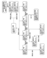
- FIG. 2 illustrates an embodiment of a building data structure for the building shown in FIG.
- FIG. 3 is a system configuration diagram showing a building data processing system including a building data processing device and a server according to the present invention.
- FIG. 4 is a functional block diagram showing an embodiment of a building data processing device according to the present invention.
- FIG. 5 is a diagram showing an example of parts of a building displayed on a display device.
- FIG. 6 is a front view of the exterior wall of the building shown in FIG.
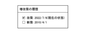
- FIG. 7 is a diagram showing an example of a screen showing the expansion/renovation history displayed on the display unit.
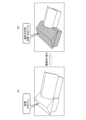
- FIG. 8 is a diagram showing a change in history from a new building to a renovated building.
- FIG. 9 is a diagram showing an example of displaying floor area.
- FIG. 10 is a diagram showing the exterior of the building shown in FIG. 1 when the roof and exterior wall of the building are damaged.
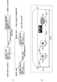
- FIG. 11 is a diagram showing a building data structure in which subsequently acquired state information of parts is linked to the building data structure shown in FIG. 2 .
- FIG. 12 is a diagram showing an example of building data and a drawing of a building displayed based on the building data.
- FIG. 13 is a conceptual diagram showing the wall core area and the interior dimension area.
- FIG. 14 is a diagram showing a model of the building composed of the four pillars and the interior walls shown in FIG.
- FIG. 15 is a diagram used to explain a method for extracting four interior walls that make up the floor area from the modeled diagram shown in FIG.
- FIG. 16 is a diagram used to explain a method for calculating the center line of each inner wall from the extracted part information (vertex polygons) of the four inner walls.
- FIG. 17 is a diagram used to explain how to identify pairs of inner walls that are in an "adjacent" relationship among the four extracted inner walls and how to calculate the intersections of the center lines of the pairs of inner walls.
- FIG. 18 is a schematic diagram of the interior walls that make up the floor area used in the interior area calculation.
- FIG. 19 is a diagram used to explain how to specify pairs of inner walls that are in an "adjacent" relationship among the four extracted inner walls and how to calculate intersections of the inner radial lines of the pairs of inner walls.
- FIG. 20 is a diagram used to explain a method for calculating the inner wall area from the coordinates of the intersections of four inner radial lines.
- Figure 21 is a diagram used to explain a method for extracting a portion (pillar) sandwiched between the "adjacency relationships" of an identified inner wall pair, and a method for obtaining the vertex coordinates on the inner diameter side of the extracted pillar.
- FIG. 20 is a diagram used to explain a method for calculating the inner wall area from the coordinates of the intersections of four inner radial lines.
- Figure 21 is a diagram used to explain a method for extracting a portion (pillar) sandwiched between the "adjacency relationships" of an identified inner wall pair, and a method for obtaining the vertex coordinates on the inner
- FIG. 22 is a diagram used to explain a method for calculating the inner diameter pillar area from the vertex coordinates on the inner diameter side of the pillar and the coordinates of the intersection of the inner diameter lines of the inner wall pair.
- FIG. 23 is a flowchart showing an embodiment of a building data processing method according to the present invention.
- FIG. 1 shows the exterior of a building created using a modeling tool applied to a building data structure
- FIG. 2 shows an embodiment of the building data structure for the building shown in FIG. 1.
- the building 10 shown in Figure 1 is composed of multiple parts, including a roof 11, four exterior walls including exterior walls 12 and 13, a door 14 arranged on exterior wall 12, and two windows 15 and 16 arranged on exterior wall 13.
- the building data structure includes part information consisting of identifiers that identify multiple parts constituting the building 10, part types that indicate the types of each of the multiple parts associated with the identifiers, shape information that indicates the three-dimensional shapes of the multiple parts, and status information that indicates the status of the multiple parts, and part relationship information that indicates the relationships between the multiple parts, and is represented as an effective graph with the part information as nodes and the part relationship information as edges.
- the multiple parts that make up the building 10 are given identifiers (e.g., E1 to E10) that identify the parts. If there are four exterior walls that make up the building 10, each of the four exterior walls is given a different identifier (E4 to E7).
- the part type indicating the type of each of the multiple parts associated with the identifier includes information indicating one or more of the following parts: exterior wall, interior wall, roof, foundation, pillar, beam, floor, ceiling, fixtures, and equipment.
- the shape information indicating the three-dimensional shapes of multiple body parts associated with an identifier can be, for example, three-dimensional data of the vertices of a polygon (hereinafter referred to as "polygon data") when the shape of the body part is a polygon.
- the polygon data for each body part can be created using a modeling tool.
- the status information indicating the condition of multiple parts includes the damage type, damage size, extent of damage, flood depth, investigator comments, or images.
- the images are damage images taken of the damage area of the building (house).
- the status information includes information that can be prepared in advance, such as damage images, information calculated using a calculation method for information useful for the intended use, and other information that is generated and input later, such as information input by the user.
- the part information consists of the part type, shape information, and status information associated with the identifier.
- the building data structure also includes part relationship information that indicates the relationships between multiple parts.
- the part relationship information includes information indicating one or more of the following relationships: aggregation relationship, dependency relationship, adjacency relationship, ownership relationship, and time series relationship.
- an aggregation relationship refers to the relationship between a first part and a second part that is a subordinate structure of the first part. For example, if the part type is "Roof 11" and there are two “Roof Planes” that are subordinate structures to that "Roof 11,” then there is an aggregation relationship between "Roof 11" and the two “Roof Planes.”
- dependency refers to the relationship between a first part and a second part when the first part depends on the structure of the second part. For example, if the first part is the “roof 11" and this "roof 11" is installed on the second part, which is the four "exterior walls 12, 13, etc.”, the first part, the "roof 11", depends on the structure of the second part, which is the four "exterior walls 12, 13, etc.” Conversely, if the first part is the four "exterior walls 12, 13, etc.” and the second part is the “roof 11", the four "exterior walls 12, 13, etc.” of the first part depend on the second part, the "roof 11". In other words, the "roof 11" and the four "exterior walls 12, 13, etc.” are mutually dependent.
- the adjacency relationship refers to the relationship between a first part and a second part of the same type when the first part and the second part are adjacent to each other.
- adjacent exterior walls e.g., exterior wall 12 and exterior wall 13
- two adjacent windows 15, 16 arranged on the same exterior wall 13 are also adjacent to each other.
- the possession relationship refers to the relationship between a first part and a second part when the first part possesses the second part as a component.
- first part is “exterior wall 12" and the second part is "door 14" which is a fixture arranged on “exterior wall 12”
- second part is “windows 15, 16” which are fixtures arranged on “exterior wall 3”
- “exterior wall 13” is in a possession relationship with “windows 15, 16”.
- a chronological relationship refers to, for example, a relationship regarding the history of the same part when it is expanded or remodeled. If the first part of the new construction is a "floor” and the second part after the expansion or remodeling is a "floor” that is an expansion or remodeling of the "floor” of the first part of the new construction, then the first part of the new construction, the "floor,” and the second part after the expansion or remodeling, the "floor,” are in a chronological relationship.
- the building data structure is expressed as an effective graph in which the "part information" of each part of the building, which is composed of part type, shape information, and status information associated with an identifier, is the node, and "part relationship information" such as aggregation relationships, dependency relationships, adjacency relationships, ownership relationships, and chronological relationships is the edge.
- the building data structure of the building being surveyed may include information about nearby damaged buildings.
- the building data processing system is capable of communicating between the building data processing devices 100, 100-1 and the server 200 via a network 202.
- the building data processing devices 100, 100-1 are computers in the disaster prevention department, property tax department, etc., of a local government. Note that the building data processing devices 100, 100-1 may also be computers in other businesses (e.g., insurance companies), and the number of building data processing devices 100, 100-1 that can be connected to the server 200 is not limited to two, as shown in FIG. 3.
- Server 200 is, for example, a server of a local government, and includes database 210 that stores building data of buildings under the jurisdiction of the local government.
- the building data managed by database 210 has a building data structure as shown in FIG. 2.
- the hardware of the building data processing device 100 which is configured by a computer, includes a processor 110 , a memory 120 , a database 130 , a display 140 , an input/output interface 150 , and an operation unit 160 .
- the processor 110 is composed of a CPU (Central Processing Unit) and other components, and executes various programs including the operation system stored in the memory 120, controls each part of the building data processing device 100, and performs calculations and display control, etc., which will be described later.
- CPU Central Processing Unit
- Memory 120 includes flash memory, ROM (Read-only Memory), RAM (Random Access Memory), a hard disk drive, etc.
- Flash memory, ROM, or a hard disk drive is a non-volatile memory that stores various programs, etc., including an operating system and a modeling tool (3D modeling software) that is applied to the building data structure.
- RAM functions as a working area for processing by processor 110, and temporarily stores programs, etc., stored in flash memory, etc.
- the processor 110 may have a portion of memory 120 (RAM) built in.
- memory 120 may store building data, building damage information, etc.
- the database 130 can be the same as the database 210 of the server 200. In this case, communication with the server 200 is not necessary. Also, when using the database 210 of the server 200, the database 130 can be omitted.
- the display 140 displays necessary drawings of the building in response to instructions from the processor 110, and is also used as part of a GUI (Graphical User Interface) when receiving various information from the operation unit 160.
- GUI Graphic User Interface
- the display 140 may be included in the building data processing device 100 if the building data processing device 100 is configured as a tablet terminal or a notebook computer, or may be an external display connected to the building data processing device 100 if the building data processing device 100 is configured as a desktop computer.
- the input/output interface 150 includes a connection unit that can be connected to an external device, and a communication unit that can be connected to a network.
- a connection unit that can be connected to an external device a Universal Serial Bus (USB), a High-Definition Multimedia Interface (HDMI) (HDMI is a registered trademark), etc. can be applied.
- the processor 110 can exchange necessary data with the server 200 and other external devices via the input/output interface 150.
- the operation unit 160 includes a pointing device such as a mouse, a keyboard, etc., and functions as part of a GUI that uses the display screen of the display unit 140 to accept various information inputs and instruction inputs by the user.
- a pointing device such as a mouse, a keyboard, etc.
- FIG. 4 is a functional block diagram mainly showing the functions of the processor 110 of the building data processing device 100 shown in FIG. 3.
- the processor 110 functions as a calculation method identification unit 112, a display control unit 114, and an information generation unit 116.
- the processor 110 acquires building data for the building to be surveyed from the server 200 via the input/output interface 150, and temporarily stores the data in the memory 120.
- the calculation method specification unit 112 accepts input of the intended use of the building data from the operation unit 160, and specifies a calculation method for information useful for the intended use based on the accepted intended use.
- the intended use of the building data includes one or more of residential damage certification survey work, fixed asset tax survey work, urban planning work, and vacant house management work. Even for the same intended use, it may be effective to switch the calculation method for the same part information when standards change due to amendments to the laws and regulations that underpin the work.
- the standards for damage assessment often change due to changes in national guidelines, so by interpreting differences in guideline versions as differences in use and adding them to the calculation specification, it is possible to obtain an effect that is useful for improving explainability, such as comparing old and new results.
- the display control unit 114 receives display or non-display instruction input for each part of the building from the operation unit 160, and causes the display device 140 to display the received part, its dimensions, and status information. That is, the display control unit 114 uses the building data stored in the memory 120 and executes the modeling tool to cause the display device 140 to display the part of the building for which display instruction input for each part of the building has been received from the operation unit 160.
- Figure 5 shows an example of a part of a building displayed on the display.
- Figure 5 (A) shows an example of the display when all the check boxes for displaying building parts are checked (i.e., when the display of all parts is specified), and Figure 5 (B) shows an example of the display when only the "exterior wall" check box for displaying building parts is checked.
- the building data includes part type for each part that makes up the building, shape information (vertex polygons) that indicates the three-dimensional shape of the part, and part relationship information that indicates the relationships between each part. Therefore, the display control unit 114 can use the shape information and part relationship information for each part to combine the parts and display the part desired by the user on the display 140.
- shape information verex polygons
- part relationship information indicates the relationships between each part. Therefore, the display control unit 114 can use the shape information and part relationship information for each part to combine the parts and display the part desired by the user on the display 140.
- FIG. 6 is a front view of the exterior walls of the building shown in FIG. 5(B).
- the display control unit 114 can arbitrarily enlarge, reduce, translate, or rotate the drawing of the part displayed on the display 140 in response to an instruction input from the operation unit 160. Note that FIG. 6 shows front views of two exterior walls on the first floor and two exterior walls on the second floor.
- the information generating unit 116 can calculate the dimensions and area of each exterior wall based on the shape information (vertex polygon) of each exterior wall and display it on the display 140.
- the display control unit 114 displays the image by superimposing it on the drawing of the corresponding part.
- the exterior wall on the right side of the first floor is damaged in FIG. 6.
- the user can input an image (damage image) of the damaged area as status information indicating the condition of the damaged part.
- the damage image is data that contains information included in the status information of the part, in which only the damaged area has been photographed in advance, and is treated as part of the input data.
- the damage dimensions and damage position data are also input by the inspector as status information of the part along with the damage image.
- the dimensions of the damage indicated by the damage image shown in FIG. 6 are 0.3 m in length and 0.5 m in width.
- the "image size" as the number of pixels when the damage image is displayed on the display 140 is automatically calculated by the display control unit 114. For example, if the input damage dimension is 1 meter, the display control unit 114 will draw the damage image size at 100 pixels, with 1 pixel per centimeter. The position data of the damage image can be input by the investigator by moving the damage image appropriately on the display screen.
- the information generation unit 116 calculates the damage size and the area ratio of the damaged area to the area of the part, and displays the calculation results on the display 140.
- the information generation unit 116 also calculates the distance from the damaged area to the surrounding parts.
- Investigators can determine the extent of damage based on the size of the damage in the area and the area percentage, and enter the determined extent of damage.
- the damage size (damage area) and area ratio calculated in this manner are added as condition information (building damage information) for the corresponding area.
- the processor 110 also accepts user input (input by the investigator) of the degree of damage for each damaged area, and the received information on the degree of damage is added as condition information (building damage information) for the corresponding area.
- the investigator can further enter the type of damage to the area (e.g. peeling, cracks) and investigator comments, and in the case of building damage due to flooding, the flood depth, etc. can be entered as condition information for the area.
- the information generation unit 116 can generate information useful for residential damage assessment survey work (damaged area, area ratio, etc.) and display it on the display 140, and also record it by linking it to building data.
- the building data of the building being surveyed stored in memory 120 has, as part relationship information, a chronological relationship regarding the history of the same part in relation to expansions and renovations.
- the display control unit 114 receives instructions to display or hide each part of the building from the operation unit 160, and displays the received parts, their dimensions, and status information on the display 140. If the building data has a chronological relationship as part relationship information, it further receives input from the inspector such as renovation or new construction, and displays on the display 140 the part information of the newly constructed parts or renovated parts.
- the display control unit 114 causes the display 140 to display the building's expansion and renovation history.
- Figure 7 shows an example of a screen showing the renovation and expansion history displayed on the display.
- the investigator uses the screen of the display 140, which shows the renovation history shown in Figure 7, and the operation unit 160 to select renovation or new construction.
- the display control unit 114 When the display control unit 114 receives a command to switch from the expansion/renovation history displayed on the display 140 to the renovation or new construction history, it causes the display 140 to display part and status information based on the part information linked to the switched history.
- the display screen of the display 140 switches from a drawing of the new building to a drawing of the renovated building.
- Figure 8 shows the change in history from a newly constructed building to a renovated building.
- Figure 8(A) shows a drawing of the newly constructed building
- Figure 8(B) shows a drawing of the renovated building.
- the parts shown in gray indicate the renovated parts.
- Figure 9 shows an example of how floor area is displayed.
- the calculation method identification unit 112 When the calculation method identification unit 112 receives input from the operation unit 160 of the use of the building data for fixed asset tax investigation work, it identifies a calculation method for calculating the floor area, and the information generation unit 116 uses the building data (part information and part relationship information) of the building to be investigated stored in the memory 120 to execute the identified calculation method, thereby calculating the floor area useful for the fixed asset tax investigation work.
- the information generation unit 116 determines the length and width of the floor from the shape information (vertex polygons) of four adjacent walls (exterior walls/interior walls) and calculates the floor area.
- the floor area may be calculated for each compartment such as a room, or for each floor including rooms, bathrooms, washrooms, and corridors, etc., and is calculated according to the floor area calculation method of the local government.
- the information generation unit 116 can display the floor area calculated in this manner on the display 140 and also record it by linking it to the building data.
- FIG. 10 is a diagram showing the exterior of the building shown in FIG. 1 when the roof and exterior walls of the building are damaged.
- the damage to the roof is breakage of roof plane E2 having identifier (E2), and the damage to the exterior wall is peeling of exterior wall E5 having identifier (E5).
- an inspector can use the operation unit 160 to identify the damaged building being inspected and the damaged areas of that damaged building, input the damage size (1m x 2m) and area condition (damage) of roof plane E2, and input the damage size (1m x 2m) and area condition (peeling) of exterior wall E5.
- the processor 110 When the processor 110 receives input of the damage size (1m x 2m) and part condition (damage) of the roof plane E2, it links the damage size (1m x 2m) and part condition (peeling) of the roof plane E2 to the building data of the affected building stored in the memory 120 and stores them as status information indicating the state of the damaged part (roof plane E2); similarly, when it receives input of the damage size (2m x 1m) and part condition (peeling) of the exterior wall E5, it stores the damage size (2m x 1m) and part condition (peeling) of the exterior wall E5 to the building data of the affected building as status information indicating the state of the damaged part (exterior wall E5).
- FIG. 11 is a diagram showing a building data structure in which subsequently acquired part status information is linked to the building data structure shown in FIG. 2.
- the subsequently acquired part status information is status information having the damage size (1m x 2m) and part status (broken) of roof plane E2, as explained in FIG. 10, and status information having the damage size (2m x 1m) and part status (peeling) of exterior wall E5.
- the processor 110 of the building data processing device 100 converts the updated graph-structured building data of the damaged buildings stored in the memory 120 into a JSON (JavaScript Object Notation) file and transmits it to the server 200 via the network 202.
- JSON JavaScript Object Notation
- the inspector can also photograph the damaged area with a camera and input the damage image into the building data processing device 100.
- the processor 110 links the input damage image to the damaged area as status information of the damaged area in the building data of the building being inspected, and stores it in the memory 120.
- the image file in which this damage image is recorded can be linked to a JSON file and transmitted to the server 200.
- the building data processing device 100 When the building data processing device 100 receives an instruction input from the operation unit 160 to identify a damaged building, it requests the server 200 to send a JSON file of the damaged building, and in response to the transmission request, the server 200 transmits the JSON file of the corresponding damaged building to the building data processing device 100.
- the processor 110 of the building data processing device 100 restores a building information graph from the received JSON file and displays a drawing of the damaged building on the display 140.
- the building data in a graph structure is converted into a JSON file and sent/received, but the file format to be converted is not limited to a JSON file and may be another text format file.
- Figure 12 shows an example of building data and a drawing of a building displayed based on that building data, particularly in the case of displaying damaged areas.
- the processor 110 identifies the area (exterior wall E5) for which dimensional calculation is required by acquiring the area identifier (E5) from the area status (damage (peeling)) indicating the damaged area as shown in FIG. 12(A), and also identifies the areas in the ownership relationship (two windows E9, E10 with identifiers (E9, E10)) from the area relationship information (in this example, ownership relationship) that can be traced from the identified exterior wall E5.
- the processor 110 acquires area information for each identified area (exterior wall E5, windows E9, E10).
- the processor 110 performs the necessary dimensional calculation processing according to the part information for each part and the type of relationship between the parts.
- Processor 110 calculates the distance from the left end of exterior wall E5 to the left end of window E9 based on polygon data appropriately extracted from shape information (polygon data) of exterior wall E5 and window E9, and the relationship (ownership relationship) between exterior wall E5 and windows E9 and E10. That is, processor 110 calculates the distance from the left end of exterior wall E5 to the left end of window E9 from the difference between the polygon data showing the three-dimensional data of the left end of exterior wall E5 in FIG. 12 among the polygon data of exterior wall E5, and the polygon data showing the three-dimensional data of the left end of window E9 in FIG. 12 among the polygon data of window E9.
- the processor 110 calculates the outer perimeter dimensions of the windows E9 and E10 based on the polygon data of the windows E9 and E10, respectively, and calculates the distance between the windows E9 and E10 based on the polygon data extracted from the relationship (adjacency relationship) between the windows E9 and E10.
- the damage size (2 m x 1 m in this example) of the damage (peeling) on the exterior wall E5 is input by the inspector, but the damage area and area ratio are calculated by the processor 110.
- the damage image can be pasted onto the drawing of the exterior wall E5 as described in Figure 6.
- the processor 110 calculates the distance (2 m) from the right edge of the damage in exterior wall E5 to the right edge of exterior wall E5 in FIG. 12 based on the damage information of exterior wall E5 (damage size and damage location data) and the polygon data of exterior wall E5, and calculates the distance (4 m) from the right edge of window E10 to the left edge of the damage based on the polygon data of window E10 and damage information (damage size and damage location data).
- the processor 110 can calculate the required distance (dimension) at the damaged area (external wall E5) and display it on the display 140.
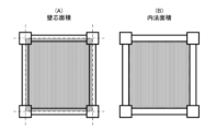
- Figure 13 is a conceptual diagram showing the wall core area and the inside area, where Figure 13(A) shows the wall core area and Figure 13(B) shows the inside area.
- Figure 14 shows a model of a building made up of the four pillars and interior walls shown in Figure 13, based on part information and part relationship information.
- a building composed of four pillars and interior walls has four pillars E3, E5, E7, E9 with identifiers (E3, E5, E7, E9) and four interior walls E2, E4, E6, E8 with identifiers (E2, E4, E6, E8).
- an inner wall E2 is provided between pillars E9 and E3
- an inner wall E4 is provided between pillars E3 and E5
- an inner wall E6 is provided between pillars E5 and E7
- an inner wall E8 is provided between pillars E7 and E9.
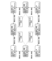
- Example of wall core area calculation> 15 to 17 are conceptual diagrams each showing an example of a procedure for calculating a wall core area.
- the processor 110 searches for a closed circuit that can be traced by the part relationship information in which the relationship is "adjacent relationship," and obtains the part information of the inner walls E2, E4, E6, and E8 included in the closed circuit.
- the processor 110 calculates the centerline of each of the four inner walls E2, E4, E6, and E8 based on the part information (vertex polygons) of the walls, as shown in FIG. 16.
- the processor 110 identifies pairs of adjacent inner walls based on the part relationship information of "adjacency relationship" as shown in FIG. 17, and calculates the intersection of the center lines of the pairs.
- the processor 110 calculates the area from the coordinates of the four intersections calculated in (3).
- the floor area calculated in this way becomes the wall core area shown in FIG. 13(A).
- Example of calculation of interior area> 18 to 22 are diagrams showing an example of a procedure for calculating an interior area.
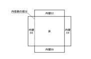
- Figure 18 is a schematic diagram of the interior walls that make up the floor area.
- the processor 110 extracts the interior walls E2, E4, E6, and E8 that make up the floor area, similar to (1) of "Wall core area calculation", and obtains the location information of the interior walls E2, E4, E6, and E8.
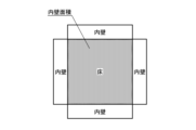
- the processor 110 calculates the line segments on the inner diameter side of the closed circuit for each of the inner walls E2, E4, E6, and E8 from the vertex polygons of the part information as shown in FIG. 18.
- the processor 110 identifies pairs of adjacent inner walls based on the part relationship information of "adjacency relationship" as shown in FIG. 19, and calculates the coordinates of the intersection of the inner radial lines of the pair.
- the processor 110 calculates the inner wall area based on the coordinates of the intersections of the four inner diameter lines calculated in (3), as shown in FIG. 20.
- the processor 110 extracts the parts (four pillars E3, E5, E7, E9) sandwiched by the "adjacency relationship" from the "adjacency relationship" of the inner wall pair identified in (3), and obtains part information of the pillars E3, E5, E7, E9.
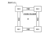
- the processor 110 obtains the vertex coordinates of the inner diameter side of each of the pillars E3, E5, E7, E9 from the vertex polygons included in the part information of the pillars E3, E5, E7, E9, as shown in FIG. 21.
- the processor 110 calculates the inner diameter column area of each of the columns E3, E5, E7, and E9 from the apex coordinates of the inner diameter side of each of the columns E3, E5, E7, and E9 obtained in (5) and the coordinates of the four inner diameter line intersections of the inner wall pair calculated in (3).
- the apex coordinates of the inner diameter side of the column and the coordinates of the inner diameter line intersections are the apex coordinates of the diagonal corners of the rectangle of the inner diameter column, and the difference between the x coordinates (the left-right coordinates in FIG.
- the inner diameter column area can be calculated by the product of the vertical length and the horizontal length of the rectangle of the inner diameter column.
- the processor 110 calculates the interior area shown in FIG. 13(B) by subtracting the total value of the interior column areas of the four columns E3, E5, E7, and E9 calculated in (6) from the interior wall area calculated in (3).
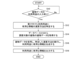
- FIG. 23 is a flowchart showing an embodiment of a building data processing method according to the present invention.
- the building data processing method shown in FIG. 23 is a method performed by the building data processing device 100 shown in FIG. 3.
- the processor 110 determines whether or not the intended use of the building data has been input from the operation unit 160 (step S10), and when the input of the intended use of the building data is accepted (if "Yes"), it identifies a calculation method for information useful for the intended use based on the accepted intended use (step S12).
- the intended use of the building data includes one or more of residential damage certification survey work, fixed asset tax survey work, urban planning work, and vacant house management work. Even for the same business use, it may be effective to switch the calculation method for the same part information if the standards change due to amendments to the laws and regulations that govern the work.
- the processor 110 acquires building data of the building to be surveyed from the server 200 and temporarily stores it in the memory 120 (step S14).
- the building data is as described in the embodiment of the building data processing device 100, and a detailed description is omitted here.
- the processor 110 uses the part information and part relationship information for each part contained in the building data stored in the memory 120 to execute the calculation method identified in step S12 and generate information useful for the intended use (step S16).
- the processor 110 can output the information thus generated that is useful for the intended use to the display 140 and/or to the memory 120, and store it in association with the identifier of the corresponding part of the building data stored in the memory 120 (step S18).
- the processor 110 uses the building data and executes a modeling tool to display drawings of one or more parts desired by the user on the display 140, and when an input is received of an intended use of the building data, for example, for residential damage certification survey work, the processor 110 calculates the dimensions and area of each part of the damaged building based on the shape information (vertex polygons) of the part, and displays the calculation results on the display 140.
- the processor 110 receives input of the dimensions of the damage through the investigator's operation of the operation unit 160, it calculates the damage area ( m2 ) and area ratio (ratio of the damage area to the part area) (%) and displays them on the display 140.
- the processor 110 when the processor 110 receives input of a use of the building data, such as for fixed asset tax investigation work, it calculates the floor area of the building being investigated for fixed asset tax assessment purposes using the part information and part relationship information for each part contained in the building data.
- the floor area can be calculated by calculating the wall core area as shown in FIG. 13, or by calculating the interior area, and the processor 110 calculates the information (floor area) that is useful for the fixed asset tax assessment according to the calculation method identified in step S12.
- the processor 110 includes a time series relationship as part relationship information, and when it receives a change of history from the expansion/renovation history displayed on the display 140, it can display part and status information on the display 140 based on the part information linked to the switched history. Furthermore, the processor 110 can calculate the floor area of the new building or the floor area after the expansion/renovation using the part information and part relationship information corresponding to the part displayed on the display 140.
- a building data processing system composed of one or more client building data processing devices 100, 100-1, etc. and a server 200 has been described as an example, but the building data processing device of the present invention may also perform building data processing independently by storing building data in a database or memory within the building data processing device.
- the hardware structure of a processing unit that executes various processes is various processors as shown below.
- the various processors include a CPU, which is a general-purpose processor that executes software (programs) and functions as various processing units, a Programmable Logic Device (PLD), such as an FPGA (Field Programmable Gate Array), which is a processor whose circuit configuration can be changed after manufacture, and a dedicated electrical circuit, such as an ASIC (Application Specific Integrated Circuit), which is a processor with a circuit configuration designed specifically to execute specific processes.
- PLD Programmable Logic Device
- FPGA Field Programmable Gate Array
- ASIC Application Specific Integrated Circuit
- a single processing unit may be configured with one of these various processors, or may be configured with two or more processors of the same or different types (e.g., multiple FPGAs, or a combination of a CPU and an FPGA). Multiple processing units may also be configured with one processor. Examples of multiple processing units configured with one processor include, first, a form in which one processor is configured with a combination of one or more CPUs and software, as represented by computers such as clients and servers, and this processor functions as multiple processing units. Second, a form in which a processor is used that realizes the functions of the entire system, including multiple processing units, with a single IC (Integrated Circuit) chip, as represented by a System On Chip (SoC). In this way, the various processing units are configured using one or more of the various processors described above as a hardware structure.
- SoC System On Chip
- the hardware structure of these various processors is an electrical circuit that combines circuit elements such as semiconductor elements.
Landscapes
- Business, Economics & Management (AREA)
- Physics & Mathematics (AREA)
- Engineering & Computer Science (AREA)
- Tourism & Hospitality (AREA)
- Theoretical Computer Science (AREA)
- General Physics & Mathematics (AREA)
- General Business, Economics & Management (AREA)
- Health & Medical Sciences (AREA)
- Strategic Management (AREA)
- Marketing (AREA)
- Human Resources & Organizations (AREA)
- General Health & Medical Sciences (AREA)
- Economics (AREA)
- Primary Health Care (AREA)
- Computer Graphics (AREA)
- Geometry (AREA)
- Software Systems (AREA)
- Development Economics (AREA)
- Educational Administration (AREA)
- Management, Administration, Business Operations System, And Electronic Commerce (AREA)
Abstract
複数の利用用途に対して利用可能な建物データから各利用用途に有用な情報を生成することができる建物データ処理装置及び方法並びに建物データ構造を提供する。建物データ処理装置(100)は、建物を構成する複数の部位を識別する識別子と、識別子に関連付けられた複数の部位のそれぞれの種別を示す部位種別、複数の部位の3次元形状を示す形状情報、及び複数の部位の状態を示す状態情報とからなる部位情報と、複数の部位の関係性を示す部位関係情報とから構成された建物データを記憶するメモリ(120)と、プロセッサ(110)とを備え、プロセッサ(110)は、建物データの利用用途の入力を受け付け、受け付けた利用用途に基づいて利用用途に有用な情報の演算方法を特定し、メモリ(120)に記憶された部位情報及び部位関係情報を使用して特定した演算方法を実行し、利用用途に有用な情報を生成する。
Description
本発明は建物データ処理装置及び方法並びに建物データ構造に係り、特に複数の利用用途に対して汎用的に利用可能な建物データ構造、及びその建物データ構造の建物データから複数の利用用途に有用な情報を生成する技術に関する。
自治体業務には、建物の調査や評価に関する業務が複数あり、それぞれで建物図面などによる部位別の寸法や属性の情報が必要である。
例えば、災害時の住家被害認定調査業務では、自治体職員が現地に出向いて被災建物を目視確認することにより、建物の部位ごとに図面の作成と損傷の記録を行う。一方で、保険会社が行う損害認定調査業務でも同種の調査を行うが、建物部位ごとの損害集計基準が異なるため、自治体が作成した建物被害情報をそのまま使用することはできない。また、固定資産税評価における建物調査でも部位別の寸法を計測するが、特に建物面積について内法面積、壁芯面積など詳細な演算方法の情報が必要となる。このように業務用途ごとに必要な建物情報には共通する項目と異なる項目があり、一つの業務で作成した図面データ等の静的なデータを別の業務で活用することが困難である。
一方、被災物の被害の程度を判定できる知識を持たない者でも、被災地域において被災物の被害の程度を認定するために必要な情報を収集できる被害調査システムが提案されている(特許文献1)。
特許文献1に記載の被害調査システムは、被災物に関する情報を収集管理する管理サーバ装置と、表示部及び写真撮影部を有し、管理サーバ装置にネットワークを介して接続される携帯端末装置と、を含んで構成される。携帯端末装置において被災物の被害の程度の判断基準を指定する判断基準指定部と、撮影された写真の画像データと指定された被災物の被害の程度の判断基準とを含む被災物情報を携帯端末装置から管理サーバ装置に送信する被災物情報送信部と、を備える。
この被害調査システムによれば、被災物の被害の程度を判定できる知識を持たない者でも、判断基準指定部にて被災物が該当すると思われる被害の程度の判断基準を指定し、写真撮影部にて被災物の写真を撮影し、被災物情報送信部にて被災物情報を管理サーバ装置に送信することにより、管理サーバ装置において被災物の被害の程度を認定するために必要な情報を収集することができる。
また、専門家以外の個人でも容易に利用することができる地震時建物内被害評価装置が提案されている(特許文献2)。
特許文献2に記載の地震時建物内被害評価装置は、建物データ及び地震動データに基づいて地震応答を計算し、地震応答、設置物データ及び床データに基づいて転倒確率、移動確率および移動量を算出し、転倒確率に基づいて転倒危険性を評価すると共に移動確率及び移動量に基づいて移動危険性を評価し、地震応答、建物データ及び非構造部位データに基づいて非構造部位損傷度を評価し、転倒確率、移動確率及び移動量、非構造部位損傷度、設置物データならびに部屋データに基づいて人的被害発生可能性を評価し、転倒危険性及び移動危険性ならびに非構造部位損傷度に基づいて建物内避難支障度を評価する。
特許文献1に記載の被害調査システムは、被災地域において被災物の被害の程度を認定するために必要な情報を収集する専用のシステムであり、また、特許文献2に記載の地震時建物内被害評価装置も、非構造部位損傷度、人的被害発生可能性及び建物内避難支障度を評価する専用の装置である。即ち、特許文献1、2には、複数の利用用途に対して汎用的に利用可能な建物データ構造に関する記載がなく、その建物データ構造の建物データを使用して、容易に複数の利用用途に有用な情報を生成する技術は記載されていない。
本発明はこのような事情に鑑みてなされたもので、複数の利用用途に対して汎用的に利用可能な建物データ構造、及びその建物データ構造の建物データから複数の利用用途に有用な情報を生成することができる建物データ処理装置及び方法並びに建物データ構造を提供することを目的とする。
上記目的を達成するために第1態様に係る発明は、建物を構成する複数の部位を識別する識別子と、識別子に関連付けられた複数の部位のそれぞれの種別を示す部位種別、複数の部位の3次元形状を示す形状情報、及び複数の部位の状態を示す状態情報とからなる部位情報と、複数の部位の関係性を示す部位関係情報とから構成された建物データを記憶するメモリと、プロセッサとを備えた建物データ処理装置であって、プロセッサは、建物データの利用用途の入力を受け付け、受け付けた利用用途に基づいて利用用途に有用な情報の演算方法を特定し、メモリに記憶された部位情報及び部位関係情報を使用して特定した演算方法を実行し、利用用途に有用な情報を生成する、建物データ処理装置である。
本発明の第1態様によれば、建物データの利用用途の入力を受け付けると、受け付けた利用用途に基づいて利用用途に有用な情報の演算方法を特定し、メモリに記憶された部位情報及び部位関係情報を使用して特定した演算方法を実行し、利用用途に有用な情報を生成するため、ユーザは、利用用途に有用な情報を簡単に取得することができる。
本発明の第2態様に係る建物データ処理装置は、第1態様において、部位種別は、外壁、内壁、屋根、基礎、柱、梁、床、天井、建具、及び設備のうちの1以上の部位を示す情報を含むことが好ましい。
本発明の第3態様に係る建物データ処理装置は、第1態様において、部位関係情報は、第1部位と第1部位の下位構造の第2部位との関係を示す集約関係、第1部位が第2部位の構造に依存する場合の第1部位と第2部位との関係を示す依存関係、同種の第1部位と第2部位とが隣接する場合の第1部位と第2部位との関係を示す隣接関係、第1部位が第2部位を構成要素として保有する場合の第1部位と第2部位との関係を示す保有関係、及び増改築に伴う同一の部位の履歴に関する時系列関係のうちの1以上の関係を示す情報を含むことが好ましい。
本発明の第4態様に係る建物データ処理装置は、第1態様において、状態情報は、損傷種別、損傷サイズ、被害程度、浸水深さ、調査員コメント、又は画像を含むことが好ましい。
本発明の第5態様に係る建物データ処理装置は、第1態様において、調査対象の建物の建物データは、調査対象の建物の周辺で被災した被災建物に関する情報を含むことが好ましい。
本発明の第6態様に係る建物データ処理装置は、第1態様において、利用用途は、住家被害認定調査業務、固定資産税調査業務、都市計画業務、及び空き家管理業務のうちの1以上の用途を含むことが好ましい。
本発明の第7態様に係る建物データ処理装置は、第1態様から第6態様のいずれかにおいて、プロセッサは、生成した情報を、部位の状態情報として部位に対応する識別子に関連付けてメモリに記憶させる。
本発明の第7態様によれば、部位に関連して利用用途に有用な情報が生成されると、生成された情報は、その部位に対応する識別子に関連付けて部位の状態情報としてメモリに記憶される。
本発明の第8態様に係る建物データ処理装置は、第1態様において、プロセッサは、建物データの利用用途として建物の住家被害認定調査業務を受け付けると、受け付けた住家被害認定調査業務に有用な建物被害情報の演算方法を特定し、建物の部位ごとに表示又は非表示の指示入力を受け付け、受け付けた部位、該部位の寸法、及び状態情報を表示器に表示させ、表示器に表示された部位に対応する部位情報及び部位関係情報を使用して特定した演算方法を実行し、状態情報である建物被害情報を生成する。
本発明の第9態様に係る建物データ処理装置は、第8態様において、建物被害情報は、損傷画像、損傷サイズ、損傷が占める面積割合又は浸水深さを示す情報を含むことが好ましい。
本発明の第10態様に係る建物データ処理装置は、第9態様において、プロセッサは、損傷ごとに被害程度のユーザ入力を受け付け、建物被害情報は、被害程度を含むことが好ましい。
本発明の第11態様に係る建物データ処理装置は、第1態様において、プロセッサは、建物データの利用用途として建物の固定資産税調査業務を受け付けると、受け付けた固定資産税調査業務に有用な床面積の演算方法を特定し、部位関係情報に含まれる時系列関係に基づいて建物の増改築履歴を表示器に表示させ、表示器に表示された増改築履歴から履歴の切り替えを受け付けると、切り替えた履歴に紐づく部位情報に基づいて部位及び状態情報を表示器に表示させ、表示器に表示された部位に対応する部位情報及び部位関係情報を使用して特定した床面積の演算方法を実行し、状態情報である床面積を生成する。
第12態様に係る発明は、建物を構成する複数の部位を識別する識別子と、識別子に関連付けられた複数の部位のそれぞれの種別を示す部位種別、複数の部位の3次元形状を示す形状情報、及び複数の部位の状態を示す状態情報とからなる部位情報と、複数の部位の関係性を示す部位関係情報とから構成された建物データを記憶するメモリと、プロセッサとを備えた建物データ処理装置におけるプロセッサが実行する建物データ処理方法であって、建物データの利用用途の入力を受け付けるステップと、受け付けた利用用途に基づいて利用用途に有用な情報の演算方法を特定するステップと、メモリに記憶された部位情報及び部位関係情報を使用して特定した演算方法を実行し、利用用途に有用な情報を生成するステップと、を含む建物データ処理方法である。
本発明の第13態様に係る建物データ処理方法は、第12態様において、建物データの利用用途として建物の住家被害認定調査業務を受け付けるステップと、受け付けた住家被害認定調査業務に有用な建物被害情報の演算方法を特定するステップと、建物の部位ごとに表示又は非表示の指示入力を受け付け、受け付けた部位、該部位の寸法、及び状態情報を表示器に表示させるステップと、表示器に表示された部位に対応する部位情報及び部位関係情報を使用して特定した演算方法を実行し、状態情報である建物被害情報を生成するステップと、を含む。
本発明の第14態様に係る建物データ処理方法は、第12態様において、建物データの利用用途として建物の固定資産税調査業務を受け付けるステップと、受け付けた固定資産税調査業務に有用な床面積の演算方法を特定するステップと、部位関係情報に含まれる時系列関係に基づいて建物の部位ごとの増改築履歴を表示器に表示させるステップと、表示器に表示された増改築履歴の中から履歴の切り替えを受け付けると、切り替えた履歴に紐づく部位情報に基づいて部位及び状態情報を表示器に表示させるステップと、表示器に表示された部位に対応する部位情報及び部位関係情報を使用して特定した床面積の演算方法を実行し、状態情報である床面積を生成するステップと、を含む。
第15態様に係る発明は、建物を構成する複数の部位を識別する識別子と、識別子に関連付けられた複数の部位のそれぞれの種別を示す部位種別、複数の部位の3次元形状を示す形状情報、及び複数の部位の状態を示す状態情報とからなる部位情報と、複数の部位の関係性を示す部位関係情報と、を備え、部位情報をノードとし、部位関係情報をエッジとする有効グラフとして表現された建物データ構造である。
本発明の第16態様に係る建物データ構造は、第15態様において、部位種別は、外壁、内壁、屋根、基礎、柱、梁、床、天井、建具、及び設備のうちの1以上の部位を示す情報を含むことが好ましい。
本発明の第17態様に係る建物データ構造は、第15態様において、部位関係情報は、第1部位と第1部位の下位構造の第2部位との関係を示す集約関係、第1部位が第2部位の構造に依存する場合の第1部位と第2部位との関係を示す依存関係、同種の第1部位と第2部位とが隣接する場合の第1部位と第2部位との関係を示す隣接関係、第1部位が第2部位を構成要素として保有する場合の第1部位と第2部位との関係を示す保有関係、及び増改築に伴う同一の部位の履歴に関する時系列関係のうちの1以上の関係を示す情報を含むことが好ましい。
本発明の第18態様に係る建物データ構造は、第15態様において、状態情報は、損傷種別、損傷サイズ、被害程度、浸水深さ、調査員コメント、又は画像を含むことが好ましい。
本発明によれば、複数の利用用途に対して汎用的に利用可能な建物データ構造を提供することができる。また、この建物データ構造の建物データを使用することで、熟練者でなくても簡単な選択操作により、複数の利用用途に有用な情報を取得ことができる。
以下、添付図面に従って本発明に係る建物データ処理装置及び方法並びに建物データ構造の好ましい実施形態について説明する。
[建物データ構造]
本発明に係る建物データ構造について説明する。
本発明に係る建物データ構造について説明する。
図1は、建物データ構造に適用されたモデリングツールを使用して作成された建物の外観を示す図であり、図2は、図1に示した建物の建物データ構造の実施形態を示す図である。
図1に示す建物10は、屋根11と、外壁12、13を含む4つの外壁と、外壁12に配設されたドア14と、外壁13に配設された2つの窓15、16とを含む複数の部位から構成されている。
図1及び図2に示すように建物データ構造は、建物10を構成する複数の部位を識別する識別子と、識別子に関連付けられた複数の部位のそれぞれの種別を示す部位種別、複数の部位の3次元形状を示す形状情報、及び複数の部位の状態を示す状態情報とからなる部位情報と、複数の部位の関係性を示す部位関係情報と、を備え、部位情報をノードとし、部位関係情報をエッジとする有効グラフとして表現されたものである。
建物10を構成する複数の部位には、部位を識別する識別子(例えば、E1~E10)が付される。建物10を構成する部位として、4つの外壁が存在する場合には、4つの外壁の各外壁には、異なる識別子(E4~E7)が付される。
識別子に関連付けられた複数の部位のそれぞれの種別を示す部位種別は、例えば、外壁、内壁、屋根、基礎、柱、梁、床、天井、建具、及び設備のうちの1以上の部位を示す情報を含む。
また、識別子に関連付けられた複数の部位の3次元形状を示す形状情報は、例えば、部位の形状を多角形(ポリゴン)とした場合の、ポリゴンの頂点の3次元データ(以下、「ポリゴンデータ」という)とすることができる。部位ごとのポリゴンデータは、モデリングツールを使用して作成することができる。
複数の部位の状態を示す状態情報は、損傷種別、損傷サイズ、被害程度、浸水深さ、調査員コメント、又は画像を含む。画像は、建物(家屋)の損傷範囲を撮影した損傷画像である。状態情報は、損傷画像のように事前に準備することができる情報と、利用用途に有用な情報の演算方法により演算される情報、その他、ユーザにより入力される情報等の後発的に生成され、入力される情報を含む。
部位情報は、識別子に関連付けられた部位種別、形状情報、及び状態情報により構成される。
また、建物データ構造は、複数の部位の関係性を示す部位関係情報を備える。
部位関係情報は、集約関係、依存関係、隣接関係、保有関係、及び時系列関係のうちの1以上の関係を示す情報を含む。
ここで、集約関係は、第1部位と第1部位の下位構造の第2部位との関係をいう。例えば、部位種別が「屋根11」の場合、その「屋根11」に対して下位構造の2つの「屋根平面」が存在する場合、「屋根11」と2つの「屋根平面」とは集約関係にある。
依存関係は、第1部位が第2部位の構造に依存する場合の第1部位と第2部位との関係をいう。例えば、第1部位が「屋根11」であり、この「屋根11」が第2部位である4つの「外壁12、13等」上に設けられている場合、第1部位の「屋根11」は、第2部位である4つの「外壁12、13等」の構造に依存する。また、逆に第1部位を4つの「外壁12、13等」とし、第2部位を「屋根11」として場合、第1部位の4つの「外壁12、13等」は、第2部位の「屋根11」に依存する。即ち、「屋根11」と4つの「外壁12、13等」とは、相互に依存関係にある。
隣接関係は、同種の第1部位と第2部位とが隣接する場合の第1部位と第2部位との関係をいう。例えば、4つの外壁のうちの隣り合う外壁(例えば、外壁12と外壁13)は、相互に隣接関係にある。また、同じ外壁13に配設された隣り合う2つの窓15、16も相互に隣接関係にある。
保有関係は、第1部位が第2部位を構成要素として保有する場合の第1部位と第2部位との関係をいう。例えば、第1部位が「外壁12」であり、第2部位が「外壁12」に配設された建具の「ドア14」の場合、「外壁12」が「ドア14」を保有する保有関係にあり、また、第1部位が「外壁13」であり、第2部位が「外壁3」に配設された建具の「窓15、16」の場合、「外壁13」が「窓15、16」を保有する保有関係にある。
時系列関係は、例えば、増改築に伴う同一の部位の履歴に関する関係をいう。新築の第1部位が「床」であり、増改築後の第2部位が、新築の第1部位の「床」を増改築した「床」の場合、これらの新築の第1部位「床」と増改築後の第2部位「床」とは時系列関係にある。
そして、図2に示すように建物データ構造は、識別子に関連付けられた部位種別、形状情報、及び状態情報等により構成された、建物の各部位の「部位情報」をノードとし、集約関係、依存関係、隣接関係、保有関係、及び時系列関係等の「部位関係情報」をエッジとする有効グラフとして表現されたものである。
尚、調査対象の建物の建物データ構造には、周辺で被災した被災建物に関する情報を含めるようにしてもよい。
[建物データ処理システム]
図3は、本発明に係る建物データ処理装置とサーバとから建物データ処理システムを示すシステム構成図である。
図3は、本発明に係る建物データ処理装置とサーバとから建物データ処理システムを示すシステム構成図である。
図3に示すように建物データ処理システムは、建物データ処理装置100、100-1と、サーバ200とがネットワーク202により通信可能になっている。
建物データ処理装置100、100-1は、自治体の災害対策課、資産税課等のコンピュータである。尚、建物データ処理装置100、100-1は、他の事業者(例えば、保険会社)のコンピュータであってもよし、サーバ200に接続可能な建物データ処理装置100、100-1の台数は、図3に示すように2台に限らない。
サーバ200は、例えば、自治体のサーバであり、自治体が管轄する建物の建物データを記憶するデータベース210を備えている。データベース210により管理される建物データは、図2に示したような建物データ構造を有している。
[建物データ処理装置のハードウェア構成]
コンピュータにより構成される建物データ処理装置100のハードウェアは、プロセッサ110、メモリ120、データベース130、表示器140、入出力インターフェース150、及び操作部160を備える。
コンピュータにより構成される建物データ処理装置100のハードウェアは、プロセッサ110、メモリ120、データベース130、表示器140、入出力インターフェース150、及び操作部160を備える。
プロセッサ110は、CPU(Central Processing Unit)等から構成され、メモリ120に記憶されたオペレーションシステムを含む各種のプログラムを実行し、建物データ処理装置100の各部を統括制御するとともに、後述する演算及び表示制御等を実行する。
メモリ120は、フラッシュメモリ、ROM(Read-only Memory)、及びRAM(Random Access Memory)、ハードディスク装置等を含む。フラッシュメモリ、ROM又はハードディスク装置は、オペレーションシステム、建物データ構造に適用されるモデリングツール(3次元モデリングソフト)を含む各種のプログラム等を記憶する不揮発性メモリである。RAMは、プロセッサ110による処理の作業領域として機能するとともに、フラッシュメモリ等に格納されたプログラム等を一時的に記憶する。尚、プロセッサ110が、メモリ120の一部(RAM)を内蔵していてもよい。また、メモリ120は、建物データ及び建物被害情報等を記憶していてもよい。
データベース130は、サーバ200のデータベース210と同様のデータベースとすることができる。この場合、サーバ200との通信は不要である。また、サーバ200のデータベース210を利用する場合には、データベース130は省略することができる。
表示器140は、プロセッサ110からの指示により建物の必要な図面を表示したり、操作部160から各種の情報を受け付ける場合のGUI(Graphical User Interface)の一部としても使用される。
表示器140は、建物データ処理装置100がタブレット端末やノートパソコンで構成される場合には、建物データ処理装置100に包含されるものでもよいし、建物データ処理装置100がデスクトップパソコンで構成される場合には、建物データ処理装置100に接続された外部の表示器でもよい。
入出力インターフェース150は、外部機器と接続可能な接続部、及びネットワークと接続可能な通信部等を含む。外部機器と接続可能な接続部としては、USB(Universal Serial Bus)、HDMI(High-Definition Multimedia Interface)(HDMIは登録商標)等を適用することができる。プロセッサ110は、入出力インターフェース150を介してサーバ200や他の外部機器との間で必要なデータのやり取りを行うことができる。
操作部160はマウス等のポインティングデバイス、キーボード等を含み、表示器140の表示画面を使用し、ユーザ操作による各種の情報の入力、及び指示の入力を受け付けるGUIの一部として機能する。
[建物データ処理装置の実施形態]
図4は、本発明に係る建物データ処理装置の実施形態を示す機能ブロック図である。
図4は、本発明に係る建物データ処理装置の実施形態を示す機能ブロック図である。
図4は、主に図3に示した建物データ処理装置100のプロセッサ110の機能を示す機能ブロック図である。
図4において、プロセッサ110は、演算方法特定部112、表示制御部114、及び情報生成部116として機能する。
まず、プロセッサ110は、操作部160からの指示入力に応じて、調査対象の建物の建物データをサーバ200から入出力インターフェース150を介して取得し、メモリ120に一時的に記憶させる。
演算方法特定部112は、操作部160から建物データの利用用途の入力を受け付け、受け付けた利用用途に基づいて利用用途に有用な情報の演算方法を特定する。ここで、建物データの利用用途は、住家被害認定調査業務、固定資産税調査業務、都市計画業務、及び空き家管理業務のうちの1以上の用途を含む。同一の業務用途であっても業務の根拠法令の改正などにより基準が変わることで、同じ部位情報に対する演算方法を切り替えることが有効な場合がある。特に住家被害認定調査業務では国の指針の変更により被害判定の基準がたびたび変わるため、指針のバージョンの違いを用途の違いと解釈し、演算特定に加えることで、新旧の結果の比較など説明性の向上に役立つ効果が得られる。
<住家被害認定調査業務の用途>
次に、建物データの利用用途として、住家被害認定調査業務の用途の入力を受け付けた場合について説明する。
次に、建物データの利用用途として、住家被害認定調査業務の用途の入力を受け付けた場合について説明する。
災害時の住家被害認定調査では、被災建物の部位ごとに部位の寸法、損傷サイズ(損傷面積)、損傷が占める面積割合を計算する。
表示制御部114は、操作部160から建物の部位ごとに表示又は非表示の指示入力を受け付け、受け付けた部位、その部位の寸法、及び状態情報を表示器140に表示させる。即ち、表示制御部114は、メモリ120に記憶された建物データを使用し、モデリングツールを実行することで、操作部160から建物の部位ごとに表示の指示入力を受け付けた部位を、表示器140に表示させる。
図5は、表示器に表示される建物の部位の一例を示す図である。
図5(A)は、建物の部位別の表示のチェックボックスの全てにチェックを入れた場合(即ち、全ての部位の表示を指示した場合)の表示例を示し、図5(B)は、建物の部位別の表示のチェックボックスのうちの「外壁」のみにチェックを入れた場合の表示例を示している。
建物データは、建物を構成する部位ごとに部位種別、部位の3次元形状を示す形状情報(頂点ポリゴン)、各部位の関係性を示す部位関係情報を有するため、表示制御部114は、各部位の形状情報及び部位関係情報を使用し、各部位を組み合わせてユーザ所望の部位を表示器140に表示させることができる。
図6は、図5(B)に示した建物の外壁の正面図である。表示制御部114は、操作部160からの指示入力に応じて、表示器140に表示される部位の図面を、任意に拡縮、並進又は回転させることができる。尚、図6には、1階の2つの外壁と2階の2つの外壁の正面図が表示されている。
情報生成部116は、各外壁の形状情報(頂点ポリゴン)に基づいて各外壁の寸法、面積を計算して表示器140に表示させることができる。
また、部位の状態を示す状態情報として部位の画像を有する場合、表示制御部114は、対応する部位の図面に画像を重ねて表示する。図6に示す例では、図6上で1階の右側の外壁が損傷している。ユーザ(調査員)は、損傷箇所を撮影した画像(損傷画像)を、損傷した部位の状態を示す状態情報として入力することができる。即ち、損傷画像は、部位の状態情報に含まれる情報として、予め損傷個所のみが撮影されたデータであり、入力データの一部として扱われる。このとき、損傷画像とともに、損傷の寸法、損傷位データも調査員により部位の状態情報として入力される。図6に示す損傷画像が示す損傷の寸法は、縦が0.3m、横が0.5mである。
ただし、損傷画像を表示器140に表示するときの画素数としての「画像サイズ」は、表示制御部114が自動計算する。例えば、入力された損傷の寸法が1メートルの場合、表示制御部114は、例えば、1センチメートル当たり1ピクセルとして、損傷画像サイズを100ピクセルで描画する。損傷画像の位置データは、調査員が表示画面上で損傷画像を適宜移動させることで入力することができる。
情報生成部116は、損傷サイズ、部位面積に対する損傷面積の面積割合を計算し、計算結果を表示器140に表示させる。本例では、図6に示した1階の右側の損傷した外壁の面積は、7.5m2(=2.5×2.0)であり、損傷面積は0.15m2(=0.3×0.5)であるため、面積割合は2.0%(=(0.3/7.5)×100)である。情報生成部116は、損傷箇所の周辺部位との距離計算なども実行する。
調査員は、部位の損傷サイズ、面積割合から被害程度を認定し、認定した被害程度を入力することができる。
このようにして計算された損傷サイズ(損傷面積)及び面積割合は、対応する部位の状態情報(建物被害情報)として追加される。また、プロセッサ110は、損傷部位ごとに被害程度のユーザ入力(調査員による入力)を受け付け、受け付けた被害程度の情報は、対応する部位の状態情報(建物被害情報)として追加される。調査員は、更に部位の損傷種別(例えば、剥離、ひび割れ)、調査員コメントを入力することができ、建物被害が浸水の場合には浸水深さなどを、部位の状態情報として入力することができる。
これにより、情報生成部116は、住家被害認定調査業務に有用な情報(損傷面積、面積割合など)を生成して表示器140に表示し、また、建物データに紐付けて記録することができる。
<固定資産税調査業務の用途>
次に、建物データの利用用途として、固定資産税調査業務の用途の入力を受け付けた場合について説明する。
次に、建物データの利用用途として、固定資産税調査業務の用途の入力を受け付けた場合について説明する。
建物の固定資産税調査業務では、固定資産税評価の一つとして床面積を求める必要がある。
いま、メモリ120に記憶された調査対象の建物の建物データが、部位関係情報として、増改築に伴う同一の部位の履歴に関する時系列関係を有する場合について説明する。
表示制御部114は、操作部160から建物の部位ごとに表示又は非表示の指示入力を受け付け、受け付けた部位、その部位の寸法、及び状態情報を表示器140に表示させるが、建物データが部位関係情報として時系列関係を有する場合には、更に調査員からの改築、新築などの入力を受け付けることで、新築の部位又は改築の部位の部位情報を使用して表示器140に表示させる。
表示制御部114は、建物データが部位関係情報として時系列関係を有する場合、建物の増改築履歴を表示器140に表示させる。
図7は、表示器に表示される増改築履歴を示す画面の一例を示す図である。
調査員は、図7に示した増改築履歴を示す表示器140の画面及び操作部160を使用し、改築又は新築を選択する。
表示制御部114は、表示器140に表示された増改築履歴から、改築又は新築の履歴の切り替えを受け付けると、切り替えた履歴に紐づく部位情報に基づいて部位及び状態情報を表示器140に表示させる。
例えば、新築から改築への履歴の切り替えが行われると、表示器140の表示画面は、新築の建物の図面から改築された建物の図面に切り替わる。
図8、新築の建物から改築された建物への履歴の切り替えを示す図である。図8(A)は新築の建物の図面を示し、図8(B)は改築された建物の図面を示し、特に図8(B)において、グレーで表示した部分が改築された部位を示す。
図9は、床面積の表示例を示す図である。
演算方法特定部112は、建物データの利用用途として、固定資産税調査業務の用途の入力を操作部160から受け付けると、床面積を演算する演算方法を特定し、情報生成部116は、メモリ120に記憶された調査対象の建物の建物データ(部位情報及び部位関係情報)を使用し、特定した演算方法を実行することで、固定資産税調査業務の用途に有用な床面積を算出する。
情報生成部116は、例えば、互いに隣接関係を有する4つの壁(外壁/内壁)の形状情報(頂点ポリゴン)から床の縦横のサイズを特定し、床面積を算出する。床面積は、部屋等の区画ごとに算出する場合、部屋、浴室、洗面所、及び廊下等を含む各階ごとの床面積を算出する場合等があり、自治体の床面積の算出方法にしたがって行う。
情報生成部116は、このようにして計算した床面積を表示器140に表示し、また、建物データに紐付けて記録することができる。
<部位ごとの損傷の記録>
図10は、図1に示した建物の屋根及び外壁が損傷している場合の建物の外観を示す図である。
図10は、図1に示した建物の屋根及び外壁が損傷している場合の建物の外観を示す図である。
図10において、屋根の損傷は、識別子(E2)を有する屋根平面E2の破損であり、外壁の損傷は、識別子(E5)を有する外壁E5の剥離である。調査員は、建物データ処理装置100において、操作部160を使用して調査対象の被災建物及びその被災建物の損傷部位を特定し、屋根平面E2の損傷サイズ(1m×2m)及び部位状態(破損)を入力し、外壁E5の損傷サイズ(1m×2m)及び部位状態(剥離)を入力することができる。
プロセッサ110は、屋根平面E2の損傷サイズ(1m×2m)及び部位状態(破損)の入力を受け付けると、メモリ120に記憶されている被災建物の建物データに、屋根平面E2の損傷サイズ(1m×2m)及び部位状態(剥離)を、損傷部位(屋根平面E2)の状態を示す状態情報として紐付けて記憶させ、同様に外壁E5の損傷サイズ(2m×1m)及び部位状態(剥離)の入力を受け付けると、被災建物の建物データに、外壁E5の損傷サイズ(2m×1m)及び部位状態(剥離)を、損傷部位(外壁E5)の状態を示す状態情報として記憶させる。
図11は、図2に示した建物データ構造に、後発的に取得した部位の状態情報が紐付けられた建物データ構造を示す図である。後発的に取得した部位の状態情報は、図10で説明したように屋根平面E2の損傷サイズ(1m×2m)及び部位状態(破損)を有する状態情報と、外壁E5の損傷サイズ(2m×1m)及び部位状態(剥離)を有する状態情報である。
建物データ処理装置100のプロセッサ110は、メモリ120に記憶され、更新された被災建物のグラフ構造の建物データを、JSON(JavaScript Object Notation)ファイルに変換し、ネットワーク202を介してサーバ200に送信する。
また、調査員は、損傷部位をカメラで撮影し、損傷画像を建物データ処理装置100に入力させることができる。プロセッサ110は、入力した損傷画像を、調査対象の建物の建物データ中の損傷部位の状態情報として、損傷部位に紐付けてメモリ120に記憶させる。この損傷画像が記録された画像ファイルは、JSONファイルに紐付けてサーバ200に送信することができる。
次に、遠隔の建物データ処理装置100で被災建物を表示する場合について説明する。
建物データ処理装置100は、操作部160により被災建物を特定する指示入力を受け付けると、サーバ200に被災建物のJSONファイルの送信を要求し、サーバ200は、送信要求に応じて、対応する被災建物のJSONファイルを建物データ処理装置100に送信する。
建物データ処理装置100のプロセッサ110は、受信したJSONファイルから建物情報グラフを復元し、表示器140に被災建物の図面を表示させる。本例では、グラフ構造の建物データは、JSONファイルに変換して送受信するが、変換するファイル形式は、JSONファイルに限らず、他のテキスト形式のファイルであってもよい。
図12は、建物データとその建物データに基づいて表示される建物の図面の一例を示す図であり、特に損傷部位を表示する場合に関して示している。
プロセッサ110は、図12(A)に示すように損傷箇所を示す部位状態(損傷(剥離))から部位識別子(E5)を取得することで、寸法計算が必要な部位(外壁E5)を特定し、また、特定した外壁E5から辿れる部位関係情報(本例では、保有関係)により、保有関係にある部位(識別子(E9、E10)を有する2つの窓E9、E10)を特定する。プロセッサ110は、特定した各部位(外壁E5、窓E9、E10)の部位情報を取得する。
プロセッサ110は、各部位の部位情報、及び部位間の関係性の種別に応じて、必要な寸法計算処理を実行する。
プロセッサ110は、外壁E5の左端から窓E9の左端までの距離を、外壁E5及び窓E9の形状情報(ポリゴンデータ)、及び外壁E5と窓E9、E10の関係性(保有関係)から適宜抽出したポリゴンデータに基づいて算出する。即ち、プロセッサ110は、外壁E5のポリゴンデータのうちの図12上で左端の3次元データを示すポリゴンデータと、窓E9のポリゴンデータのうちの図12上で左端の3次元データを示すポリゴンデータとの差から、外壁E5の左端から窓E9の左端までの距離を算出する。
同様に、プロセッサ110は、窓E9及び窓E10の外周寸法を、窓E9及び窓E10のそれぞれのポリゴンデータに基づいて算出し、窓E9と窓E10との間の距離を、窓E9と窓E10の関係性(隣接関係)から抽出したポリゴンデータに基づいて算出する。
一方、外壁E5の損傷(剥離)の損傷サイズ(本例では、2m×1m)は、調査員により入力されるが、損傷面積及び面積割合は、プロセッサ110により計算される。
外壁E5に損傷画像が紐付けられている場合には、図6で説明したように外壁E5の図面上に損傷画像を貼り付けることができる。
プロセッサ110は、図12上で外壁E5の損傷の右端から外壁E5の右端までの距離(2m)を、外壁E5の損傷情報(損傷サイズ及び損傷の位置データ)と外壁E5のポリゴンデータとに基づいて算出し、窓E10の右端から損傷の左端までの距離(4m)を、窓E10のポリゴンデータと損傷情報(損傷サイズ及び損傷の位置データ)とに基づいて算出する。
このようにしてプロセッサ110は、損傷部位(外壁E5)における必要な距離(寸法)を計算し、表示器140に表示させることができる。
[床面積の算出方法]
固定資産調査において税計算の基礎になる床面積の計算方法として、壁芯面積と内法面積とがある。
固定資産調査において税計算の基礎になる床面積の計算方法として、壁芯面積と内法面積とがある。
図13は、壁芯面積及び内法面積を示す概念図であり、図13(A)は壁芯面積を示し、図13(B)は内法面積を示す。
図14は、図13に示した4本の柱と内壁で構成された建物を、部位情報及び部位関係情報に基づいてモデル化した図である。
図14において、4本の柱と内壁で構成された建物は、識別子(E3、E5、E7、E9)を有する4本の柱E3、E5、E7、E9と、識別子(E2、E4、E6、E8)を有する4つの内壁E2、E4、E6、E8とを備える。
各柱E3、E5、E7、E9と、各内壁E2、E4、E6、E8との関係性(隣接関係)を示す部位関係情報から、柱E9と柱E3との間に内壁E2が設けられ、柱E3と柱E5との間に内壁E4が設けられ、柱E5と柱E7との間に内壁E6が設けられ、柱E7と柱E9との間に内壁E8が設けられていることが分かる。
以下では、壁芯面積計算と内法面積計算の2通りの利用用途において、図14に示した一つのモデルに対し、異なる演算を特定することで、それぞれの用途に応じた計算結果を出力することができる。
<壁芯面積計算の演算例>
図15から図17は、それぞれ壁芯面積計算の手順の一例を示す概念図である。
図15から図17は、それぞれ壁芯面積計算の手順の一例を示す概念図である。
(1)図15に示すように、床面積を構成する内壁を抽出する。プロセッサ110は、関係性が「隣接関係」である部位関係情報によって辿ることができる閉回路を探し、閉回路に含まれる内壁E2、E4、E6、E8の部位情報を取得する。
(2)プロセッサ110は、図16に示すように4つの内壁E2、E4、E6、E8の部位情報(頂点ポリゴン)に基づいて各内壁の中心線を計算する。
(3)プロセッサ110は、図17に示すように「隣接関係」の部位関係情報により隣接する内壁のペアを特定し、ペアの中心線の交点を計算する。
(4)プロセッサ110は、(3)で計算した4つの交点の座標から面積を計算する。このようにして計算した床面積は、図13(A)に示した壁芯面積となる。
<内法面積計算の演算例>
図18から図22は、それぞれ内法面積計算の手順の一例を示す図である。
図18から図22は、それぞれ内法面積計算の手順の一例を示す図である。
(1)図18は、床面積を構成する内壁の概略図である。図18において、プロセッサ110は、「壁芯面積計算」の(1)と同様に、床面積を構成する内壁E2、E4、E6、E8を抽出し、内壁E2、E4、E6、E8の部位情報を取得する。
(2)プロセッサ110は、各内壁E2、E4、E6、E8について、部位情報の頂点ポリゴンから、図18に示しように閉回路の内径側の線分を計算する。
(3)プロセッサ110は、図19に示すように「隣接関係」の部位関係情報により隣接する内壁のペアを特定し、ペアの内径線の交点の座標を計算する。
(4)プロセッサ110は、図20に示すように、(3)で計算した4つの内径線の交点の座標に基づいて内壁面積を計算する。
(5)プロセッサ110は、(3)で特定した内壁ペアの「隣接関係」から、「隣接関係」で挟まれた部位(4本の柱E3、E5、E7、E9)を抽出し、柱E3、E5、E7、E9の部位情報を取得する。プロセッサ110は、柱E3、E5、E7、E9の部位情報に含まれる頂点ポリゴンから、図21に示すように各柱E3、E5、E7、E9の内径側の頂点座標を取得する。
(6)プロセッサ110は、図22に示すように、(5)で取得した各柱E3、E5、E7、E9の内径側の頂点座標と、(3)で計算した内壁ペアの4つの内径線交点の座標とから、各柱E3、E5、E7、E9の内径柱面積を計算する。尚、柱の内径側の頂点座標と内径線交点の座標とは、内径柱の矩形の対角の頂点座標であり、かつ2つの頂点座標のx座標(図22上の左右方向の座標)の差は、内径柱の矩形の横の長さであり、y座標(図22上の上下方向の座標)の差は、内径柱の矩形の縦の長さであるため、内径柱の矩形の縦の長さと横の長さの積により内径柱面積を計算することができる。
(7)プロセッサ110は、(6)で計算した4本の柱E3、E5、E7、E9の内径柱面積の合計値を、(3)で計算した内壁面積から差し引くことで、図13(B)に示した内法面積を算出する。
[建物データ処理方法の実施形態]
図23は、本発明に係る建物データ処理方法の実施形態を示すフローチャートである。
図23は、本発明に係る建物データ処理方法の実施形態を示すフローチャートである。
尚、図23に示す建物データ処理方法は、図3に示した建物データ処理装置100により行われる方法である。
図23において、プロセッサ110は、操作部160からの建物データの利用用途の入力の有無を判別し(ステップS10)、建物データの利用用途の入力を受け付けると(「Yes」の場合)、受け付けた利用用途に基づいて利用用途に有用な情報の演算方法を特定する(ステップS12)。建物データの利用用途は、住家被害認定調査業務、固定資産税調査業務、都市計画業務、及び空き家管理業務のうちの1以上の用途を含む。同一の業務用途であっても業務の根拠法令の改正などにより基準が変わることで、同じ部位情報に対する演算方法を切り替えることが有効な場合がある。
続いて、プロセッサ110は、操作部160からの指示入力に応じて、調査対象の建物の建物データをサーバ200から取得し、メモリ120に一時的に記憶させる(ステップS14)。尚、建物データは、建物データ処理装置100の実施形態において説明した通りであり、ここでは詳細な説明は省略する。
プロセッサ110は、メモリ120に記憶された建物データに含まれる各部位の部位情報及び部位関係情報を使用し、ステップS12において特定した演算方法を実行し、利用用途に有用な情報を生成する(ステップS16)。
プロセッサ110は、このようにして生成した利用用途に有用な情報を表示器140に出力し、及び/又はメモリ120に出力し、メモリ120に記憶された建物データの対応する部位の識別子に関連付けて記憶させることができる(ステップS18)。
即ち、プロセッサ110は、建物データを使用し、モデリングツールを実行することで、ユーザ所望の1乃至複数の部位の図面を表示器140に表示させることができ、建物データの利用用途として、例えば住家被害認定調査業務の用途の入力を受け付けた場合、被災建物の部位ごとに、部位の形状情報(頂点ポリゴン)に基づいて各部位の寸法、面積を計算し、その計算結果を表示器140に表示させる。プロセッサ110は、調査員による操作部160の操作により損傷の寸法の入力を受け付けると、損傷面積(m2)、面積割合(部位面積に対する損傷面積の割合)(%)を計算し、表示器140に表示させる。
また、プロセッサ110は、建物データの利用用途として、例えば固定資産税調査業務の用途の入力を受け付けた場合、固定資産税評価のために調査対象の建物の床面積を、建物データに含まれる各部位の部位情報及び部位関係情報を使用して計算する。
床面積の算出方法は、図13に示したように壁芯面積を算出する方法、及び内法面積を算出する方法などがあり、プロセッサ110は、ステップS12で特定した演算方法にしたがって固定資産税評価に有効な情報(床面積)を計算する。
更に、プロセッサ110は、部位関係情報として時系列関係が含まれており、表示器140に表示された増改築履歴の中から履歴の切り替えを受け付けると、切り替えた履歴に紐づく部位情報に基づいて部位及び状態情報を表示器140に表示させることができる。更にまた、プロセッサ110は、表示器140に表示された部位に対応する部位情報及び部位関係情報を使用して、新築の床面積又は増改築後の床面積を計算することができる。
[その他]
本実施形態では、クライアントである1乃至複数の建物データ処理装置100、100-1等とサーバ200とから構成された建物データ処理システムを例に説明したが、本発明に係る建物データ処理装置は、建物データ処理装置内のデータベース又はメモリに建物データを記憶させておくことで、単独で建物データ処理を行うものでもよい。
本実施形態では、クライアントである1乃至複数の建物データ処理装置100、100-1等とサーバ200とから構成された建物データ処理システムを例に説明したが、本発明に係る建物データ処理装置は、建物データ処理装置内のデータベース又はメモリに建物データを記憶させておくことで、単独で建物データ処理を行うものでもよい。
また、本実施形態において、例えば、CPU(Central Processing Unit)等の各種の処理を実行する処理部(processing unit)のハードウェア的な構造は、次に示すような各種のプロセッサ(processor)である。各種のプロセッサには、ソフトウェア(プログラム)を実行して各種の処理部として機能する汎用的なプロセッサであるCPU、FPGA(Field Programmable Gate Array)などの製造後に回路構成を変更可能なプロセッサであるプログラマブルロジックデバイス(Programmable Logic Device:PLD)、ASIC(Application Specific Integrated Circuit)などの特定の処理を実行させるために専用に設計された回路構成を有するプロセッサである専用電気回路などが含まれる。
1つの処理部は、これら各種のプロセッサのうちの1つで構成されていてもよいし、同種または異種の2つ以上のプロセッサ(例えば、複数のFPGA、あるいはCPUとFPGAの組み合わせ)で構成されてもよい。また、複数の処理部を1つのプロセッサで構成してもよい。複数の処理部を1つのプロセッサで構成する例としては、第1に、クライアントやサーバなどのコンピュータに代表されるように、1つ以上のCPUとソフトウェアの組合せで1つのプロセッサを構成し、このプロセッサが複数の処理部として機能する形態がある。第2に、システムオンチップ(System On Chip:SoC)などに代表されるように、複数の処理部を含むシステム全体の機能を1つのIC(Integrated Circuit)チップで実現するプロセッサを使用する形態がある。このように、各種の処理部は、ハードウェア的な構造として、上記各種のプロセッサを1つ以上用いて構成される。
また、これらの各種のプロセッサのハードウェア的な構造は、より具体的には、半導体素子などの回路素子を組み合わせた電気回路(circuitry)である。
更に、本発明は上述した実施形態に限定されず、本発明の精神を逸脱しない範囲で種々の変形が可能であることは言うまでもない。
10…建物
11…屋根
12…外壁
13…外壁
14…ドア
15、16…窓
100…建物データ処理装置
110…プロセッサ
112…演算方法特定部
114…表示制御部
116…情報生成部
120…メモリ
130…データベース
140…表示器
150…入出力インターフェース
160…操作部
200…サーバ
202…ネットワーク
210…データベース
S10…ステップ
S12…ステップ
S14…ステップ
S16…ステップ
11…屋根
12…外壁
13…外壁
14…ドア
15、16…窓
100…建物データ処理装置
110…プロセッサ
112…演算方法特定部
114…表示制御部
116…情報生成部
120…メモリ
130…データベース
140…表示器
150…入出力インターフェース
160…操作部
200…サーバ
202…ネットワーク
210…データベース
S10…ステップ
S12…ステップ
S14…ステップ
S16…ステップ
Claims (18)
- 建物を構成する複数の部位を識別する識別子と、前記識別子に関連付けられた前記複数の部位のそれぞれの種別を示す部位種別、前記複数の部位の3次元形状を示す形状情報、及び前記複数の部位の状態を示す状態情報とからなる部位情報と、前記複数の部位の関係性を示す部位関係情報とから構成された建物データを記憶するメモリと、プロセッサとを備えた建物データ処理装置であって、
前記プロセッサは、
前記建物データの利用用途の入力を受け付け、
前記受け付けた利用用途に基づいて前記利用用途に有用な情報の演算方法を特定し、
前記メモリに記憶された前記部位情報及び前記部位関係情報を使用して前記特定した演算方法を実行し、前記利用用途に有用な情報を生成する、
建物データ処理装置。 - 前記部位種別は、外壁、内壁、屋根、基礎、柱、梁、床、天井、建具、及び設備のうちの1以上の部位を示す情報を含む、
請求項1に記載の建物データ処理装置。 - 前記部位関係情報は、第1部位と前記第1部位の下位構造の第2部位との関係を示す集約関係、第1部位が第2部位の構造に依存する場合の前記第1部位と前記第2部位との関係を示す依存関係、同種の第1部位と第2部位とが隣接する場合の前記第1部位と前記第2部位との関係を示す隣接関係、第1部位が第2部位を構成要素として保有する場合の前記第1部位と前記第2部位との関係を示す保有関係、及び増改築に伴う同一の部位の履歴に関する時系列関係のうちの1以上の関係を示す情報を含む、
請求項1に記載の建物データ処理装置。 - 前記状態情報は、損傷種別、損傷サイズ、被害程度、浸水深さ、調査員コメント、又は画像を含む、
請求項1に記載の建物データ処理装置。 - 調査対象の建物の前記建物データは、前記調査対象の建物の周辺で被災した被災建物に関する情報を含む、
請求項1に記載の建物データ処理装置。 - 前記利用用途は、住家被害認定調査業務、固定資産税調査業務、都市計画業務、及び空き家管理業務のうちの1以上の用途を含む、
請求項1に記載の建物データ処理装置。 - 前記プロセッサは、前記生成した情報を、前記部位の状態情報として前記部位に対応する識別子に関連付けて前記メモリに記憶させる、
請求項1から6のいずれか1項に記載の建物データ処理装置。 - 前記プロセッサは、前記建物データの利用用途として建物の住家被害認定調査業務を受け付けると、前記受け付けた住家被害認定調査業務に有用な建物被害情報の演算方法を特定し、
前記建物の部位ごとに表示又は非表示の指示入力を受け付け、受け付けた部位、該部位の寸法、及び前記状態情報を表示器に表示させ、
前記表示器に表示された部位に対応する前記部位情報及び前記部位関係情報を使用して前記特定した演算方法を実行し、前記状態情報である建物被害情報を生成する、
請求項1に記載の建物データ処理装置。 - 前記建物被害情報は、損傷画像、損傷サイズ、損傷が占める面積割合又は浸水深さを示す情報を含む、
請求項8に記載の建物データ処理装置。 - 前記プロセッサは、損傷ごとに被害程度のユーザ入力を受け付け、
前記建物被害情報は、前記被害程度を含む、
請求項9に記載の建物データ処理装置。 - 前記プロセッサは、前記建物データの利用用途として建物の固定資産税調査業務を受け付けると、前記受け付けた固定資産税調査業務に有用な床面積の演算方法を特定し、
前記部位関係情報に含まれる時系列関係に基づいて前記建物の増改築履歴を表示器に表示させ、
前記表示器に表示された増改築履歴から履歴の切り替えを受け付けると、前記切り替えた履歴に紐づく前記部位情報に基づいて前記部位及び前記状態情報を前記表示器に表示させ、
前記表示器に表示された前記部位に対応する前記部位情報及び前記部位関係情報を使用して前記特定した床面積の演算方法を実行し、前記状態情報である前記床面積を生成する、
請求項1に記載の建物データ処理装置。 - 建物を構成する複数の部位を識別する識別子と、前記識別子に関連付けられた前記複数の部位のそれぞれの種別を示す部位種別、前記複数の部位の3次元形状を示す形状情報、及び前記複数の部位の状態を示す状態情報とからなる部位情報と、前記複数の部位の関係性を示す部位関係情報とから構成された建物データを記憶するメモリと、プロセッサとを備えた建物データ処理装置における前記プロセッサが実行する建物データ処理方法であって、
前記建物データの利用用途の入力を受け付けるステップと、
前記受け付けた利用用途に基づいて前記利用用途に有用な情報の演算方法を特定するステップと、
前記メモリに記憶された前記部位情報及び前記部位関係情報を使用して前記特定した演算方法を実行し、前記利用用途に有用な情報を生成するステップと、
を含む建物データ処理方法。 - 前記建物データの利用用途として建物の住家被害認定調査業務を受け付けるステップと、
前記受け付けた住家被害認定調査業務に有用な建物被害情報の演算方法を特定するステップと、
前記建物の部位ごとに表示又は非表示の指示入力を受け付け、受け付けた部位、該部位の寸法、及び前記状態情報を表示器に表示させるステップと、
前記表示器に表示された部位に対応する前記部位情報及び前記部位関係情報を使用して前記特定した演算方法を実行し、前記状態情報である建物被害情報を生成するステップと、
を含む請求項12に記載の建物データ処理方法。 - 前記建物データの利用用途として建物の固定資産税調査業務を受け付けるステップと、
前記受け付けた固定資産税調査業務に有用な床面積の演算方法を特定するステップと、
前記部位関係情報に含まれる時系列関係に基づいて前記建物の部位ごとの増改築履歴を表示器に表示させるステップと、
前記表示器に表示された増改築履歴の中から履歴の切り替えを受け付けると、切り替えた履歴に紐づく前記部位情報に基づいて前記部位及び前記状態情報を前記表示器に表示させるステップと、
前記表示器に表示された前記部位に対応する前記部位情報及び前記部位関係情報を使用して前記特定した床面積の演算方法を実行し、前記状態情報である前記床面積を生成するステップと、
を含む請求項12に記載の建物データ処理方法。 - 建物を構成する複数の部位を識別する識別子と、前記識別子に関連付けられた前記複数の部位のそれぞれの種別を示す部位種別、前記複数の部位の3次元形状を示す形状情報、及び前記複数の部位の状態を示す状態情報とからなる部位情報と、
前記複数の部位の関係性を示す部位関係情報と、を備え、
前記部位情報をノードとし、前記部位関係情報をエッジとする有効グラフとして表現された建物データ構造。 - 前記部位種別は、外壁、内壁、屋根、基礎、柱、梁、床、天井、建具、及び設備のうちの1以上の部位を示す情報を含む、
請求項15に記載の建物データ構造。 - 前記部位関係情報は、第1部位と前記第1部位の下位構造の第2部位との関係を示す集約関係、第1部位が第2部位の構造に依存する場合の前記第1部位と前記第2部位との関係を示す依存関係、同種の第1部位と第2部位とが隣接する場合の前記第1部位と前記第2部位との関係を示す隣接関係、第1部位が第2部位を構成要素として保有する場合の前記第1部位と前記第2部位との関係を示す保有関係、及び増改築に伴う同一の部位の履歴に関する時系列関係のうちの1以上の関係を示す情報を含む、
請求項15に記載の建物データ構造。 - 前記状態情報は、損傷種別、損傷サイズ、被害程度、浸水深さ、調査員コメント、又は画像を含む、
請求項15に記載の建物データ構造。
Priority Applications (2)
| Application Number | Priority Date | Filing Date | Title |
|---|---|---|---|
| JP2024549979A JPWO2024070586A1 (ja) | 2022-09-27 | 2023-09-08 | |
| US19/090,044 US20250225597A1 (en) | 2022-09-27 | 2025-03-25 | Building data processing device, building data processing method, and building data structure |
Applications Claiming Priority (2)
| Application Number | Priority Date | Filing Date | Title |
|---|---|---|---|
| JP2022153367 | 2022-09-27 | ||
| JP2022-153367 | 2022-09-27 |
Related Child Applications (1)
| Application Number | Title | Priority Date | Filing Date |
|---|---|---|---|
| US19/090,044 Continuation US20250225597A1 (en) | 2022-09-27 | 2025-03-25 | Building data processing device, building data processing method, and building data structure |
Publications (1)
| Publication Number | Publication Date |
|---|---|
| WO2024070586A1 true WO2024070586A1 (ja) | 2024-04-04 |
Family
ID=90477411
Family Applications (1)
| Application Number | Title | Priority Date | Filing Date |
|---|---|---|---|
| PCT/JP2023/032835 Ceased WO2024070586A1 (ja) | 2022-09-27 | 2023-09-08 | 建物データ処理装置及び方法並びに建物データ構造 |
Country Status (3)
| Country | Link |
|---|---|
| US (1) | US20250225597A1 (ja) |
| JP (1) | JPWO2024070586A1 (ja) |
| WO (1) | WO2024070586A1 (ja) |
Cited By (1)
| Publication number | Priority date | Publication date | Assignee | Title |
|---|---|---|---|---|
| JP7732066B1 (ja) * | 2024-12-11 | 2025-09-01 | 株式会社フローワークス | 作業支援システム |
Citations (3)
| Publication number | Priority date | Publication date | Assignee | Title |
|---|---|---|---|---|
| JP2006338072A (ja) * | 2005-05-31 | 2006-12-14 | Tokyo Kaijo Nichido Chosa Service Kk | 建物の損傷調査のためのプログラム及び携帯端末 |
| JP2021174427A (ja) * | 2020-04-30 | 2021-11-01 | 株式会社大林組 | 設計支援システム、設計支援方法及び設計支援プログラム |
| WO2022059670A1 (ja) * | 2020-09-16 | 2022-03-24 | 国立大学法人東京大学 | 情報処理装置、情報処理方法及びプログラム |
-
2023
- 2023-09-08 WO PCT/JP2023/032835 patent/WO2024070586A1/ja not_active Ceased
- 2023-09-08 JP JP2024549979A patent/JPWO2024070586A1/ja active Pending
-
2025
- 2025-03-25 US US19/090,044 patent/US20250225597A1/en active Pending
Patent Citations (3)
| Publication number | Priority date | Publication date | Assignee | Title |
|---|---|---|---|---|
| JP2006338072A (ja) * | 2005-05-31 | 2006-12-14 | Tokyo Kaijo Nichido Chosa Service Kk | 建物の損傷調査のためのプログラム及び携帯端末 |
| JP2021174427A (ja) * | 2020-04-30 | 2021-11-01 | 株式会社大林組 | 設計支援システム、設計支援方法及び設計支援プログラム |
| WO2022059670A1 (ja) * | 2020-09-16 | 2022-03-24 | 国立大学法人東京大学 | 情報処理装置、情報処理方法及びプログラム |
Cited By (1)
| Publication number | Priority date | Publication date | Assignee | Title |
|---|---|---|---|---|
| JP7732066B1 (ja) * | 2024-12-11 | 2025-09-01 | 株式会社フローワークス | 作業支援システム |
Also Published As
| Publication number | Publication date |
|---|---|
| US20250225597A1 (en) | 2025-07-10 |
| JPWO2024070586A1 (ja) | 2024-04-04 |
Similar Documents
| Publication | Publication Date | Title |
|---|---|---|
| Antón et al. | Accuracy evaluation of the semi-automatic 3D modeling for historical building information models | |
| Campanaro et al. | 3D GIS for cultural heritage restoration: A ‘white box’workflow | |
| Mahdjoubi et al. | Providing real-estate services through the integration of 3D laser scanning and building information modelling | |
| Napolitano et al. | Virtual tours and informational modeling for conservation of cultural heritage sites | |
| Xu et al. | Seismic damage simulation in urban areas based on a high-fidelity structural model and a physics engine | |
| Roh et al. | An object-based 3D walk-through model for interior construction progress monitoring | |
| Nieto-Julián et al. | Implementation and management of structural deformations into historic building information models | |
| RU2644506C2 (ru) | Система управления проектами для обеспечения оптимального взаимодействия с цифровыми моделями | |
| Hong et al. | Semi-automated approach to indoor mapping for 3D as-built building information modeling | |
| Bitelli et al. | Automated voxel model from point clouds for structural analysis of cultural heritage | |
| US20240203054A1 (en) | Streamlined single software workflow with ml-based point cloud clustering for virtual reality building inspection | |
| Ma et al. | Information modeling of earthquake-damaged reinforced concrete structures | |
| Bloch et al. | Interior models of earthquake damaged buildings for search and rescue | |
| CN106446225A (zh) | 一种基于bim技术的古建筑数字化建模归档方法 | |
| Dakhil et al. | Client's role in building disaster management through building information modelling | |
| JP7595300B2 (ja) | 統合データ生成システム、施工計画管理システム、統合データ生成方法、施工計画管理方法、及びプログラム | |
| Hess et al. | Terrestrial laser scanning for the comprehensive structural health assessment of the Baptistery di San Giovanni in Florence, Italy: An integrative methodology for repeatable data acquisition, visualization and analysis | |
| Truong-Hong et al. | Validating computational models from laser scanning data for historic facades | |
| Hosny et al. | Physical distancing analytics for construction planning using 4D BIM | |
| US20250225597A1 (en) | Building data processing device, building data processing method, and building data structure | |
| Armesto et al. | Monitoring and assessing structural damage in historic buildings | |
| Zhang et al. | Hidden structural information reconstruction and seismic response analysis of high‐rise residential shear wall buildings with limited structural data | |
| Özkan et al. | Automatic completion of geometric models from point clouds for analyzing historic timber roof structures | |
| Park et al. | A comparison of network model creation algorithms based on the quality of wayfinding results | |
| Patil et al. | Implementing BIM and finite element analysis in a structural integrity investigation of curtain walls |
Legal Events
| Date | Code | Title | Description |
|---|---|---|---|
| 121 | Ep: the epo has been informed by wipo that ep was designated in this application |
Ref document number: 23871823 Country of ref document: EP Kind code of ref document: A1 |
|
| WWE | Wipo information: entry into national phase |
Ref document number: 2024549979 Country of ref document: JP |
|
| 122 | Ep: pct application non-entry in european phase |
Ref document number: 23871823 Country of ref document: EP Kind code of ref document: A1 |