WO2024069797A1 - エレベーターシステム、中継装置、第二中継装置、中継方法、及びコンピュータ読み取り可能な記録媒体 - Google Patents
エレベーターシステム、中継装置、第二中継装置、中継方法、及びコンピュータ読み取り可能な記録媒体 Download PDFInfo
- Publication number
- WO2024069797A1 WO2024069797A1 PCT/JP2022/036180 JP2022036180W WO2024069797A1 WO 2024069797 A1 WO2024069797 A1 WO 2024069797A1 JP 2022036180 W JP2022036180 W JP 2022036180W WO 2024069797 A1 WO2024069797 A1 WO 2024069797A1
- Authority
- WO
- WIPO (PCT)
- Prior art keywords
- car
- elevator
- robot
- information
- relay device
- Prior art date
- Legal status (The legal status is an assumption and is not a legal conclusion. Google has not performed a legal analysis and makes no representation as to the accuracy of the status listed.)
- Ceased
Links
Images


Classifications
-
- B—PERFORMING OPERATIONS; TRANSPORTING
- B66—HOISTING; LIFTING; HAULING
- B66B—ELEVATORS; ESCALATORS OR MOVING WALKWAYS
- B66B1/00—Control systems of elevators in general
- B66B1/02—Control systems without regulation, i.e. without retroactive action
- B66B1/06—Control systems without regulation, i.e. without retroactive action electric
- B66B1/14—Control systems without regulation, i.e. without retroactive action electric with devices, e.g. push-buttons, for indirect control of movements
- B66B1/18—Control systems without regulation, i.e. without retroactive action electric with devices, e.g. push-buttons, for indirect control of movements with means for storing pulses controlling the movements of several cars or cages
-
- B—PERFORMING OPERATIONS; TRANSPORTING
- B66—HOISTING; LIFTING; HAULING
- B66B—ELEVATORS; ESCALATORS OR MOVING WALKWAYS
- B66B17/00—Hoistway equipment
- B66B17/14—Applications of loading and unloading equipment
- B66B17/16—Applications of loading and unloading equipment for loading and unloading mining-hoist cars or cages
- B66B17/20—Applications of loading and unloading equipment for loading and unloading mining-hoist cars or cages by moving vehicles into, or out of, the cars or cages
Definitions
- the present disclosure relates to an elevator system, a relay device, a second relay device, a relay method, and a computer-readable recording medium.
- Patent Document 1 discloses a technology in which an automated guided vehicle moves between floors using a button pressing assist unit that is detachably attached to an elevator operation panel.
- the automated guided vehicle of this technology is equipped with a communication unit that communicates with a button pressing assist unit that is installed later.
- the automated guided vehicle sends a signal to press an up floor button at the elevator hall, the up floor button is pressed by the button pressing assist unit.
- the button pressing assist unit also detects when the button goes from lit to off, and transmits that signal to the automated guided vehicle.
- Patent Document 1 it is necessary to realize the robot's boarding and disembarking using only the information obtained from the elevator operation panel and the functions that can be executed from the elevator operation panel. In order to enable the robot to cooperate with the elevator in a highly efficient manner under such constraints, a great deal of human effort is required for modernizing the elevator or modifying the software, etc.
- This disclosure has been made to solve the problems described above, and aims to reduce the burden on those involved in modernization or software modifications when providing an elevator system that enables the robot to board and disembark through cooperation between the elevator and the robot.
- the elevator system of the present disclosure comprises a plurality of first relay devices, each of which corresponds to one of a plurality of elevator cars installed in a facility and is connected to each other so as to receive elevator information obtained from the car operating panel of the corresponding car and transmit executable commands from the car operating panel to each machine control device, and a second relay device, which is connected to each of the plurality of first relay devices so as to be able to communicate with each of the plurality of first relay devices.
- the second relay device comprises a second receiving unit that receives a usage request including call information from the boarding floor to the destination floor of a robot moving through the facility, and a second transmitting unit that transmits a robot call registration request to a first relay device among the plurality of first relay devices that corresponds to an assigned car to which the robot call included in the usage request is to be assigned.
- Each of the plurality of first relay devices comprises a first receiving unit that receives the robot call registration request transmitted by the second transmitting unit, and a first transmitting unit that transmits the robot call registration request received by the first receiving unit to each machine control device.
- the second relay device of the present disclosure corresponds to one of multiple elevator cars installed in the facility, receives elevator information obtained from the car operation panel of the corresponding car, and is connected so as to be able to communicate with each of the multiple first relay devices to which it is connected so as to be able to transmit executable commands from the car operation panel to each machine control device.
- the second relay device includes a second receiving unit that receives a usage request including call information from the boarding floor to the destination floor of a robot moving through the facility, and a second transmitting unit that transmits a robot call registration request to the first relay device to be transmitted to each machine control device to the first relay device corresponding to an assigned car to which the robot call included in the usage request is assigned among the multiple first relay devices.
- the relay device disclosed herein is connected so as to receive elevator information obtained from each car operating panel of multiple elevator cars installed in the facility, and transmit executable commands from the car operating panel to each machine control device corresponding to each of the multiple cars.
- the relay device includes a receiving unit that receives a usage request including call information from the boarding floor to the destination floor of a robot moving through the facility, and a transmitting unit that transmits a robot call registration request to each machine control device corresponding to an assigned car that is to be assigned the robot call included in the usage request, among the multiple cars.
- the relay method disclosed herein receives elevator information obtained from each car operating panel of multiple elevator cars installed in a facility, and transmits executable commands from the car operating panel to each machine control device corresponding to each of the multiple cars.
- the relay method includes a step of receiving a usage request including call information from the boarding floor to the destination floor of a robot moving through the facility, a step of determining an assigned car to which the robot call included in the usage request is assigned based on the elevator information, and a step of transmitting a registration request for the robot call to each machine control device corresponding to the assigned car.
- the computer-readable recording medium of the present disclosure records a relay program that causes a computer to receive elevator information obtained from each car operating panel of multiple elevator cars installed in a facility and transmit executable commands from the car operating panel to each machine control device corresponding to each of the multiple cars.
- the relay program is configured to cause a computer to receive a usage request including call information from the boarding floor to the destination floor of a robot moving through the facility, determine an assigned car to which the robot call included in the usage request is assigned based on the elevator information, and transmit a registration request for the robot call to each machine control device corresponding to the assigned car.
- This disclosure provides an elevator system that allows the robot to board and disembark through cooperation between the elevator and the robot, thereby reducing the burden on those involved in modernization or software modification.
- FIG. 1 is a configuration diagram of a building system according to a first embodiment.
- 1 is a block diagram showing the functions of an elevator system according to a first embodiment.
- FIG. 4 is a flowchart showing an operation example of the elevator system according to the first embodiment. 4 illustrates an example of selection of an assigned car by the second relay device according to the first embodiment.
- FIG. 2 is a hardware configuration diagram of a main part of the elevator system according to the first embodiment.
- FIG. 11 is a block diagram showing the functions of an elevator system according to a second embodiment. 10 is a flowchart showing an example of the operation of the elevator system according to the second embodiment.
- FIG. 11 is a block diagram showing the functions of an elevator system according to a third embodiment.
- FIG. 13 shows an example of selection of an evacuation floor by an evacuation floor selection unit.
- 13 is a flowchart showing an example of the operation of the elevator system according to the third embodiment.
- FIG. 13 is a block diagram showing the functions of an elevator system according to a fourth embodiment.
- 13 is a flowchart showing an example of the operation of the elevator system according to the fourth embodiment.
- FIG. 13 is a configuration diagram of a building system according to a fifth embodiment. A block diagram showing the functions of an elevator system according to embodiment 5.
- FIG. 1 is a configuration diagram of a building system according to a first embodiment.
- the building system is applied to a facility.
- the facility may be, for example, an indoor facility, an outdoor facility, or a facility that combines these.
- the facility may consist of, for example, one or more buildings.
- the facility may be, for example, a part of a building.
- the building system applied to a facility includes a robot 1 that moves around the facility. In this example, the robot 1 operates based on the control of a robot server 2.
- the robot 1 communicates with the robot server 2 wirelessly.
- a management room 3 is provided in the facility.
- the management room 3 is a place where a facility manager or the like manages the facility.
- the robot server 2 is provided, for example, in the management room 3.
- the building system includes an elevator system as an internal system.
- the elevator system includes an elevator.
- An elevator shaft 4 is provided in the facility.
- the shaft 4 is a space that spans multiple floors with its longitudinal direction in the vertical direction.
- An elevator machine room 5 is provided above the shaft 4.
- a landing 6 is provided on each floor in the facility. The landing 6 is a place that leads to the shaft 4.
- the elevator comprises a plurality of units and a group control device 7.
- Each unit comprises a hoist 8, a deflector sheave 9, a main rope 10, a car 11, a counterweight 12, and an individual car control device 13.
- the group control device 7, and the hoist 8, deflector sheave 9, and individual car control device 13 of each unit are provided in the machine room 5.
- the car 11 and the counterweight 12 are provided in the hoistway 4.
- the hoist 8 includes a motor that generates a driving force, and a sheave that rotates by the driving force generated by the motor.
- the main rope 10 is wound around the sheave and the deflector sheave 9 of the hoist 8.
- the main rope 10 supports the load of the car 11 on one side of the sheave of the hoist 8.
- the main rope 10 supports the load of the counterweight 12 on the other side of the sheave of the hoist 8.
- the car 11 and counterweight 12 run on opposite sides of the elevator shaft in the vertical direction via the sheaves and main ropes 10 of the elevator shaft 8, driven by the driving force generated by the motor of the elevator shaft 8.
- the car 11 travels through the elevator shaft 4 to transport users or robots inside the car 11 between multiple floors of the facility.
- the car controller 13 of each unit corresponds to a car 11 of the same unit. Each car controller 13 is electrically connected to the hoist 8 of the same unit. Each car controller 13 is connected to the corresponding car 11 through a car transmission cable 16. Each car controller 13 controls the running of the car 11 through control of the hoist 8. Each car controller 13 of each unit is electrically connected to the group management device 7 through a transmission cable 14.
- the group management device 7 accepts information on user hall calls received by a hall operating panel (not shown) installed at the elevator hall 6.
- the group management device 7 assigns the hall calls to one of the cars 11.
- the car 11 is equipped with a car operation panel 15.
- the car operation panel 15 is an elevator operation panel that accepts car call operations by elevator users. Car call information accepted by the car operation panel 15 of the car 11 is transmitted to the car control device 13 corresponding to the car 11 via the car transmission cable 16.
- the elevator system includes a plurality of first relay devices 30 and a second relay device 40.
- the first relay devices 30 are, for example, protocol converters. Each of the first relay devices 30 corresponds to one of the units.
- the first relay devices 30 are electrically connected to each machine control device 13 of the corresponding unit via a relay cable 17.
- the relay cable 17 connected to the first relay devices 30 is electrically connected to a car transmission cable 16 that connects each machine control device 13 and the car 11 in the unit to which the first relay device 30 corresponds.
- Each of the first relay devices 30 is provided in a machine room 5.
- the second relay device 40 is a separate device from the group management device 7.
- the second relay device 40 is provided in the management room 3.
- the second relay device 40 is electrically connected to the robot server 2 via a cable 18.
- the second relay device 40 may be connected to the robot server 2 wirelessly.
- the second relay device 40 is electrically connected to each of the first relay devices 30 via an elevator transmission cable 19.
- the second relay device 40 is connected to each machine control device 13 via the first relay device 30 for each unit. That is, each first relay device 30 is interposed between the corresponding machine control device 13 and the second relay device 40.
- the second relay device 40 executes each function by reading a relay program recorded on a computer-readable recording medium and operating according to the relay program.
- the recording medium on which the relay program is recorded may be, for example, one that is built into the second relay device 40 or one that is connected to the second relay device 40.
- the relay program may be installed in the second relay device 40 via a communication network such as the Internet, or may be installed in the second relay device 40 by reading it from an external portable recording medium on which the relay program is recorded.
- the robot 1 uses an elevator to access multiple floors of a facility.
- a request for use including call information is transmitted.
- the request for use is transmitted, for example, from the robot server 2 that controls the robot 1.
- the request for use may be transmitted from the robot 1.
- the call information for the robot 1 includes information on the boarding floor and destination floor of the robot 1.
- the request for use is transmitted to the second relay device 40.
- the second relay device 40 performs a process of allocating the call for the robot 1 to one of the cars 11.
- the allocation of the robot 1's call is performed, for example, based on elevator information.
- the elevator information is sent, for example, from each of the first relay devices 30 to the second relay device 40.
- the group management device 7 does not perform the process of allocating the robot 1's call to any of the cars 11.
- the second relay device 40 sends a registration request including information on the call to the first relay device 30 corresponding to the car 11 to which the robot 1's call has been allocated.
- the second relay device 40 sends information identifying the car 11 to which the robot 1's call has been allocated to the robot server 2 that controls that robot 1.
- the second relay device 40 transmits information about the call as a car call for that car 11 to the individual car control device 13 that controls that car 11.
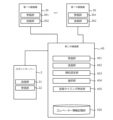
- FIG. 2 is a block diagram showing the functions of the elevator system according to the first embodiment.
- the robot server 2 includes a transmission unit 21 and a reception unit 22.
- the second relay device 40 includes a reception unit 401 as a second reception unit, a transmission unit 402 as a second transmission unit, a ranking setting unit 403, a selection unit 404, a transmission timing determination unit 405, and an elevator information storage unit 420.
- Each first relay device 30 includes a reception unit 301 as a first reception unit, and a transmission unit 302 as a first transmission unit.
- the transmitting unit 21 of the robot server 2 has a function to transmit a usage request including information on the call of the robot 1 to the receiving unit 401 of the second relay device 40, and a function to transmit a robot operation stop signal and a robot operation return signal to the receiving unit 401 of the second relay device 40.
- Robot operation here refers to elevator operation in response to a call of the robot 1.
- the robot operation stop signal is a signal requesting that robot operation be stopped due to a factor on the robot side, such as a malfunction of the robot 1.
- the robot operation return signal is a signal requesting that robot operation be resumed while robot operation is stopped.
- the receiving unit 22 of the robot server 2 has a function to receive, from the transmitting unit 402 of the second relay device 40, assigned car information that specifies the car 11 to which the call of the robot 1 is assigned.
- the receiving unit 401 of the second relay device 40 has a function to receive a request for use and a robot operation stop signal from the transmitting unit 21 of the robot server 2, and a function to receive elevator information from the transmitting unit 302 of the first relay device 30.
- the elevator information storage unit 420 has the function of storing elevator information.
- the elevator information includes information obtained from the car operation panel 15 of each unit.
- the elevator information for each unit includes car position information of the car 11, car travel direction information, door open button light illumination information, in-car destination floor button illumination information, and in-car destination floor button registration availability information.
- the ranking setting unit 403 has a function of setting the ranking of some or all of the multiple cars 11 as candidate cars to which a call from the robot 1 is to be assigned.
- the ranking setting unit 403 sets the ranking of each car 11 based on the elevator information stored in the elevator information storage unit 420.
- the selection unit 404 has a function of selecting an assigned car to which the call of the robot 1 is to be assigned from among the candidate cars whose ranks have been set by the rank setting unit 403.
- the selection unit 404 selects an assigned car based on the ranks set by the rank setting unit 403. For example, the selection unit 404 selects the candidate car whose rank has been set as the number 1 assigned car.
- the transmission timing determination unit 405 has a function of determining the timing to transmit a boarding floor car call to the assigned car selected by the selection unit 404 based on the elevator information stored in the elevator information storage unit 420.
- the transmission timing determination unit 405 determines, for example, the timing when the boarding floor and the destination floor are located in this order ahead of the car 11 in the running direction as the timing to transmit the boarding floor car call.
- the transmission unit 402 of the second relay device 40 has a function of transmitting a registration request for a boarding floor car call to the assigned car selected by the selection unit 404 and a registration request for a destination floor car call to the assigned car to the receiving unit 301 of the first relay device 30.
- the transmission unit 402 of the second relay device 40 has a function of transmitting information identifying the assigned car selected by the selection unit 404 to the receiving unit 22 of the robot server 2.
- the receiving unit 301 of the first relay device 30 has a function of receiving a call registration request and the like from the transmitting unit 402 of the second relay device 40.
- the receiving unit 301 of the first relay device 30 has a function of receiving elevator information from each unit control device 13 of the corresponding unit every time the elevator information for that unit changes.
- the transmitting unit 302 of the first relay device 30 has a function of transmitting the call registration request transmitted by the transmitting unit 402 of the second relay device 40 as a car call for the car 11 of the corresponding unit to the individual car control device 13 that controls the car 11.
- the transmitting unit 302 of the first relay device 30 has a function of transmitting elevator information to the receiving unit 401 of the second relay device 40 every time the elevator information for the corresponding unit changes.
- FIG. 3 is a flowchart showing an operation example of the elevator system according to the first embodiment. Here, a series of operations until the elevator system registers a boarding floor car call of the robot 1 will be described. This flowchart also shows a part of a relay method according to the embodiment of the present disclosure.
- step S100 the second relay device 40 judges whether the receiving unit 401 has received a usage request including information about a call to the robot 1 from the transmitting unit 21 of the robot server 2. If the judgment is found to be true, the process proceeds to step S102, and if the judgment is found to be false, the process returns to step S100.
- step S102 the ranking setting unit 403 sets the rankings of the multiple cars 11 as candidate cars based on the information stored in the elevator information storage unit 420. After the processing of step S102 is performed, the process proceeds to step S104.
- step S104 the selection unit 404 selects the candidate car that has been ranked first by the ranking setting unit 403 as the car to be assigned. After the processing of step S104 is performed, the processing proceeds to step S106.
- step S106 the transmission timing determination unit 405 determines, based on the elevator information, whether the condition that the boarding floor and the destination floor are located in that order ahead in the direction of travel of the assigned car is met. If the result shows that the condition is not met, the process returns to step S106, and if the condition is met, the process proceeds to step S108.
- step S108 the transmission unit 402 transmits a registration request for a boarding floor car call for the assigned car selected by the selection unit 404 to the reception unit 301 of the first relay device 30 corresponding to the assigned car.
- the transmission unit 402 also transmits assigned car information that identifies the assigned car selected by the selection unit 404 to the reception unit 22 of the robot server 2. Thereafter, the processing of the second relay device 40 ends.
- FIG. 4 shows an example of the selection of an assigned car by the second relay device 40 according to the first embodiment.
- the elevator has eight units, A to H.
- the request to use the robot 1 is sent to the second relay device 40 via the robot server 2 or the like when the robot 1 moves from the boarding floor to the destination floor.
- the ranking setting unit 403 acquires the elevator status for each unit based on the elevator information.
- the elevator status for each unit includes security restricted floor determination information, car position/travel direction information, and information on the distance from the boarding floor of the robot 1 to the car 11.
- the security restricted floor determination information is information that identifies a security restricted floor where boarding and alighting are restricted from a security standpoint.
- the car position/travel direction information is information that indicates whether the boarding floor and the destination floor are located in that order ahead of the travel direction of the car 11.
- a priority is set for the use of these pieces of information.
- the order of the security restricted floor determination information, car position/travel direction information, and information on the distance from the boarding floor of the robot 1 to the car 11 is from highest to lowest priority.
- the priority setting unit 403 first performs a determination process based on the security restricted floor determination information, which has the highest priority.
- the priority setting unit 403 determines whether the boarding floor or the destination floor is a security restricted floor based on the in-car destination floor button registration availability information stored in the elevator information storage unit 420.
- some elevator systems are set up to disable call registration for rear floors, which are floors located on the opposite side of the car's travel direction. In such elevator systems, the rear floors are included in the floors that cannot be registered in the in-car destination floor button registration availability information, and there is a possibility that the security restricted floors cannot be accurately identified.
- the ranking setting unit 403 reads out the in-cabin destination floor button registration availability information acquired when cage 11 most recently stopped in a non-directional manner. Then, the ranking setting unit 403 determines whether the boarding floor or destination floor of robot 1 is included in the security restricted floors that cannot be registered in the read in-cabin destination floor button registration availability information. Then, the ranking setting unit 403 excludes cages 11 of cars whose boarding floors or destination floors are included in security restricted floors from the candidate cages. In the example shown in FIG.
- the ranking setting unit 403 provisionally sets cages A to D, whose boarding floors and destination floors are service floors, to be tied for first place, and excludes cages E to H, whose boarding floors or destination floors are security restricted floors, from the candidate cages.
- the ranking setting unit 403 may, for example, omit subsequent ranking setting processing for a cage 11 that has been excluded from the candidate cages.
- the ranking setting unit 403 performs a judgment process based on the cage position/travel direction information with the next highest priority.
- the ranking setting unit 403 judges whether the boarding floor and destination floor of the robot 1 are located ahead of the cage 11 in this order in the traveling direction.
- the ranking setting unit 403 provisionally sets cars A and B, whose boarding floor and destination floor are located ahead of the cage 11 in this order in the traveling direction, to a tie for first place, and provisionally sets cars C and D, whose boarding floor and destination floor are not located ahead of the cage 11 in this order in the traveling direction, to a tie for third place.
- the ranking setting unit 403 performs a determination process based on the distance from the boarding floor, which has the next highest priority.
- the ranking setting unit 403 sets the car 11, which is closer to the boarding floor, to a higher position.
- the ranking setting unit 403 sets car A, which is one floor away from the boarding floor, to first place, and car B, which is three floors away from the boarding floor, to second place.
- the ranking setting unit 403 sets car C, which is one floor away from the boarding floor, to third place, and car D, which is two floors away from the boarding floor, to fourth place.
- the ranking setting unit 403 sets the car 11 with the lower unit number, etc., to a higher position so that there are no candidate cars with the same ranking.
- the selection unit 404 selects car A, which the ranking setting unit 403 has set as number 1, as the car to be assigned.
- the second relay device 40 receives a usage request from the robot server 2 and selects an assigned car to which the call included in the usage request is assigned.
- the second relay device 40 transmits a registration request for the call to the first relay device 30 connected to each car control device 13 that controls the assigned car via the elevator transmission cable 19.
- the first relay device 30 masquerades as the car operation panel 15 of the assigned car and transmits the registration request as a car call to the each car control device 13.
- the group management device 7 does not need a function to communicate with the second relay device 40, etc.
- the elevator and robot 1 can be linked even with a group management device 7 that does not have a communication function.
- the second relay device 40 can also distinguish between security restricted floors and floors behind, based on the in-car destination floor button registration availability information acquired at the time of the car 11's most recent non-directional stop. This reduces the possibility of erroneously determining that a rear floor is a security restricted floor, and allows the rear floor to be included in the candidate cars. This increases the number of candidate cars, making it possible to select an appropriate assigned car to improve operational efficiency.
- the second relay device 40 can set a higher priority to a car whose boarding floor and destination floor are located ahead of the car 11 in the running direction, in that order, than a car whose floor is not. This allows a car 11 that can move more smoothly from the boarding floor to the destination floor to be set to a higher priority, improving operation efficiency.
- the ranking setting unit 403 also sets the ranking of candidates for allocation based on the information stored in the elevator information storage unit 420.
- the selection unit 404 selects the candidate car that the ranking setting unit 403 has set as the first car to be allocated. This provides the advantage that the second relay device 40 can allocate a car 11 that can accommodate the robot 1 and that will arrive at the boarding floor early. In addition, because the second relay device 40 selects the car to be allocated, a further advantage is that the processing load on the group management device 7 can be reduced.
- the second relay device 40 determines that it is time to send a car call to the boarding floor of robot 1 when the condition is met that the boarding floor and destination floor of robot 1 are located in that order in the running direction of the assigned car. If a car call is made to the boarding floor and destination floor of robot 1 when these floors are located, for example, at the rear floors, an event may occur in which the car call disappears when the car 11 reverses direction.
- the above condition determination has the effect of making it possible to avoid such an event. Furthermore, it has the effect of allowing the car 11 to move smoothly to the destination floor without reversing its running direction even after the robot 1 boards.
- the elevator system of the first embodiment may employ the following modified aspects. These modified aspects may also be applied to elevator systems of other embodiments described later.
- the robot 1 may communicate with the second relay device 40 without going through the robot server 2.
- some or all of the functions of the robot server 2 and the second relay device 40 may be installed in a device provided outside the facility. Some or all of the functions of the robot server 2 and the second relay device 40 may be implemented across multiple pieces of hardware. In this case, each piece of hardware is connected to be able to communicate with each other through a communication network such as the Internet. Furthermore, some or all of the functions of the robot server 2 and the second relay device 40 may be implemented by processing and storage resources on a cloud service.
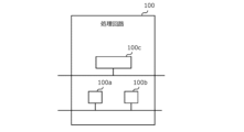
- FIG. 5 is a hardware configuration diagram of the main parts of the elevator system according to the first embodiment.
- Each function of the elevator system can be realized by a processing circuit 100.
- the processing circuit 100 includes at least one processor 100a and at least one memory 100b.
- the processing circuit may include at least one dedicated hardware 100c in addition to the processor 100a and memory 100b, or as a substitute for them.
- each function of the building system is realized by software, firmware, or a combination of software and firmware. At least one of the software and firmware is written as a program.
- the program is stored in the memory 100b.
- the processor 100a realizes each function of the elevator system by reading and executing the program stored in the memory 100b.
- the processor 100a is also called a CPU (Central Processing Unit), processing device, arithmetic unit, microprocessor, microcomputer, or DSP.
- the memory 100b is composed of non-volatile or volatile semiconductor memory such as RAM, ROM, flash memory, EPROM, and EEPROM.
- processing circuitry comprises dedicated hardware 100c
- the processing circuitry may be implemented, for example, as a single circuit, a composite circuit, a programmed processor, a parallel programmed processor, an ASIC, an FPGA, or a combination thereof.
- Each function of the elevator system can be realized by a processing circuit. Alternatively, all the functions of the elevator system can be realized collectively by a processing circuit. Some of the functions of the elevator system can be realized by dedicated hardware 100c, and other parts can be realized by software or firmware. In this way, the processing circuit realizes each function of the building system by dedicated hardware 100c, software, firmware, or a combination of these.
- Embodiment 2 In the second embodiment, differences from the example disclosed in the first embodiment will be described in particular detail. For features not described in the second embodiment, any of the features of the example disclosed in the first embodiment may be adopted.
- FIG. 6 is a block diagram showing functions of the elevator system according to embodiment 2.
- the second relay device 40 according to embodiment 2 further includes a door-open determination unit 406 in addition to the functions of the second relay device 40 according to embodiment 1.
- the door-opening determination unit 406 has the function of determining whether the assigned car selected by the selection unit 404 has arrived at the boarding floor and the door is open, based on the elevator information stored in the elevator information storage unit 420.
- FIG. 7 is a flowchart showing an example of operation of the elevator system according to embodiment 2. Here, a series of operations will be described, from when the elevator system executes the process of the flowchart shown in Fig. 5 to when it registers a boarding floor car call for the robot 1, to when it transmits a boarding instruction to the robot 1.
- step S200 the door opening judgment unit 406 judges whether the door opening condition is satisfied, that is, the door of the assigned car is open at the boarding floor of the robot 1, based on the elevator information stored in the elevator information storage unit 420.
- the door opening judgment unit 406 judges whether the current car position of the assigned car is the boarding floor, based on the car position information, and whether the door opening button light for the assigned car is on, based on the lighting information of the door opening button light. As a result, if at least one of these judgments is not satisfied, the process returns to step S200 again, and if both of these judgments are satisfied, the process proceeds to the next step S202.
- step S202 the transmitting unit 402 transmits a registration request for a destination floor car call for the assigned car selected by the selecting unit 404 to the receiving unit 301 of the first relay device 30 corresponding to the assigned car.
- step S204 the processing proceeds to step S204.
- step S204 the transmission unit 402 transmits an instruction for the robot to board the assigned car selected by the selection unit 404 to the reception unit 22 of the robot server 2.
- the door-open determination unit 406 of the second relay device 40 determines that the door of the assigned car is open at the floor where the robot 1 boards, it proceeds to the sending process of registering a car call for the destination floor. This makes it possible to register the destination floor immediately before the robot 1 boards, which has the effect of reducing the risk of a call being made to the destination floor being wasted.
- Embodiment 3 In the third embodiment, differences from the examples disclosed in the first or second embodiment will be described in particular detail. For features not described in the third embodiment, any of the features of the examples disclosed in the first or second embodiment may be adopted.
- Functions of the elevator system according to embodiment 3 Fig. 8 is a block diagram showing functions of an elevator system according to embodiment 3.
- the robot server 2 according to embodiment 3 further includes a confinement determination unit 23 in addition to the functions of embodiment 1-2.
- the second relay device 40 according to embodiment 3 further includes a robot operation determination unit 407 and an evacuation floor selection unit 408 in addition to the functions of the second relay device 40 according to embodiment 1-2.
- the trapped-in judging unit 23 has the function of judging that the robot 1 is trapped in the car 11 and notifying the building manager or the like. There are no limitations on the configuration of the trapped-in judging unit 23.
- the receiving unit 22 of the robot server 2 receives elevator information transmitted from the transmitting unit 402 of the second relay device 40. Then, the trapped-in judging unit 23 judges whether the robot 1 is trapped in the car 11 based on the received elevator information.
- the robot operation determination unit 407 has a function of determining whether to stop or resume robot operation, which transports the robot 1 to the destination floor, based on the elevator information stored in the elevator information storage unit 420. Specifically, the robot operation determination unit 407 reads out in-car destination floor button registration availability information acquired when the car 11 most recently stopped in a non-directional manner. The robot operation determination unit 407 then determines whether the condition is met that the destination floor of the robot 1 is included in the security restricted floor that cannot be registered in the in-car destination floor button registration availability information that has been read out. If the condition is met, the robot operation determination unit 407 then determines to stop robot operation.
- the robot operation determination unit 407 also determines whether to resume robot operation if the condition is no longer met within a predetermined waiting time after it has been determined that robot operation should be stopped.
- the time constraint on the waiting time is set to reduce the possibility of the robot 1 being trapped inside the car 11 and having to wait for a long time due to robot operation being stopped due to factors on the elevator side.
- the waiting time can be set as appropriate.
- the evacuation floor selection unit 408 has a function of selecting an evacuation floor to which the robot 1 is to escape, based on the elevator information stored in the elevator information storage unit 420. When the robot operation changes from suspended to resumed, it is required that the robot in the car 11 is quickly evacuated outside the car 11.
- the evacuation floor selection unit 408 selects an evacuation floor to which the robot in the car 11 is to escape, when the robot operation changes from suspended to resumed.
- FIG. 9 shows an example of the selection of an evacuation floor by the evacuation floor selection unit 408.
- the floors of the facility range from 1F to 7F
- the boarding floor of robot 1 is 2F
- the destination floor is 6F
- the car 11 in which robot 1 is riding is traveling from 2F to 6F
- the current car position is 3F.
- the evacuation floor selection unit 408 acquires the elevator status of the unit corresponding to the assigned car in which the robot 1 is riding, based on the elevator information stored in the elevator information storage unit 420.
- the elevator status here includes security restricted floor information and information on the distance from the current car position.
- a priority is set for the use of this information.
- the order of security restricted floor determination information and information on the distance from the current car position is from highest to lowest priority.
- the evacuation floor selection unit 408 first performs a judgment process based on the highest priority security restricted floor judgment information.
- the evacuation floor selection unit 408 judges whether each floor is a security restricted floor based on the in-car destination floor button registration availability information stored in the elevator information storage unit 420.
- the evacuation floor selection unit 408 reads out the in-car destination floor button registration availability information acquired at the most recent non-directional stop of the car 11, similar to the setting operation by the priority setting unit 403. Then, the evacuation floor selection unit 408 judges whether each floor is included in the security restricted floors that cannot be registered in the in-car destination floor button registration availability information that has been read out.
- the evacuation floor selection unit 408 excludes the security restricted floors 4F and 6F from the evacuation floor candidates, and provisionally sets the service floors 1F to 3F, 5F, and 7F as evacuation floor candidates.
- the evacuation floor selection unit 408 performs a determination process based on the distance from the current car position, which has the next highest priority.
- the evacuation floor selection unit 408 selects, from among the multiple candidate evacuation floors, the floor that is the shortest distance from the current car position in the current running direction of the car as the evacuation floor.
- FIG. 10 is a flowchart showing an example of the operation of the elevator system according to embodiment 3.
- a series of operations will be described, from when the elevator system transmits a boarding instruction to the robot 1 by executing the process of the flowchart shown in FIG. 7 until when it transmits a disembarking instruction to the robot 1.
- step S300 the second relay device 40 determines whether a request to stop robot operation has been issued due to a factor on the robot side.
- the second relay device 40 determines whether the receiving unit 401 has received a robot operation stop signal sent by the robot server 2. If the result of the determination is not affirmative, the process proceeds to step S302, and if the determination is affirmative, the process proceeds to step S304.
- step S302 the robot operation determination unit 407 of the second relay device 40 determines whether a determination has been made to stop robot operation due to a factor on the elevator side. If the determination is not successful, the process proceeds to step S306, and if the determination is successful, the process proceeds to step S308.
- step S304 the second relay device 40 determines whether the robot has returned to being operable.
- the second relay device 40 determines whether the receiving unit 401 has received a robot operation return signal within a predetermined waiting time after receiving a robot operation stop signal. If the result of the determination is not affirmative, the process proceeds to step S310, and if the determination is affirmative, the process proceeds to step S308.
- step S306 the door open determination unit 406 of the second relay device 40 determines whether the door of the car 11 is open at the destination floor based on the elevator information.
- the door open determination unit 406 determines whether the conditions are met in the car position information that the current car position is the destination floor and the door open button light illumination information is in the illuminated state. If the result is that the determination is not met, the process returns to step S306 again, and if the determination is met, the process proceeds to step S318.
- step S308 the evacuation floor selection unit 408 of the second relay device 40 selects an evacuation floor.
- the processing proceeds to step S312.
- step S310 the robot 1 is manually removed from the car 11.
- the confinement determination unit 23 determines that the robot 1 is confined in the car 11 and notifies the building manager, etc.
- step S312 the evacuation floor selection unit 408 of the second relay device 40 determines whether an elevator call is possible at the evacuation floor.
- the evacuation floor selection unit 408 determines whether the condition that the evacuation floor is located ahead in the elevator's travel direction from the current elevator position is met. If the result shows that the determination is not met, the process returns to step S312 again, and if the determination is met, the process proceeds to step S314.
- step S314 the transmitting unit 402 of the second relay device 40 transmits a registration request for a car call to the evacuation floor selected by the evacuation floor selecting unit 408 to the receiving unit 301 of the first relay device 30.
- step S314 the processing proceeds to step S316.
- step S316 the door open determination unit 406 of the second relay device 40 determines whether the door of the car 11 is open at the evacuation floor based on the elevator information.
- the door open determination unit 406 determines whether the conditions are met in the car position information that the current car position is the evacuation floor and the door open button light illumination information is in the illuminated state. If the result is that the determination is not met, the process returns to step S316 again, and if the determination is met, the process proceeds to step S318.
- step S318 the transmitter 402 of the second relay device transmits a robot disembarkation instruction to the receiver 22 of the robot server 2.
- the evacuation floor selection unit 408 performs evacuation floor selection processing. This leaves open the possibility of proceeding to resume robot operation even if robot operation is temporarily stopped due to a robot malfunction or the like. This reduces the effort required to manually remove the robot 1 from the car.
- the second relay device 40 can also distinguish between security restricted floors and floors behind, based on the in-car destination floor button registration availability information acquired at the time of the car 11's most recent non-directional stop. This can reduce the possibility of erroneously determining that a rear floor is a security restricted floor, thereby reducing erroneous determinations in the selection process for evacuation floors.
- the evacuation floor selection unit 408 prioritizes floors that are closer to the current car position during the evacuation floor selection process, allowing the robot 1 to be evacuated as quickly as possible.
- Embodiment 4 differ from the examples disclosed in the first to third embodiments will be described in particular detail. For features not described in the fourth embodiment, any of the features of the examples disclosed in the first to third embodiments may be adopted.
- the second relay device 40 of embodiment 4 further includes an elevator operation determination unit 409 and an erroneous determination prevention unit 410 in addition to the functions of the second relay device 40 of embodiment 3.
- the elevator operation determination unit 409 has the function of determining whether the operating status of the car 11 of each unit is in operation or out of service based on the elevator information stored in the elevator information storage unit 420.
- the erroneous judgment prevention unit 410 has a function of preventing the elevator operation judgment unit 409 from erroneously judging that the elevator is out of service when the car position is at the terminal floor, based on the elevator information stored in the elevator information storage unit 420.
- Fig. 12 is a flowchart showing an operation example of the elevator system according to embodiment 4. The routine shown in Fig. 12 is constantly executed for each unit in the elevator system.
- step S400 of the routine shown in FIG. 12 the elevator operation determination unit 409 determines whether the operating state of the car 11 of each unit is in operation or out of service based on the elevator information stored in the elevator information storage unit 420.
- the elevator operation determination unit 409 determines that the elevator is out of service if the in-car destination floor buttons for all floors are not registered and if the in-car destination floor buttons for all floors cannot be registered. Otherwise, it determines that the elevator is in operation.
- the process proceeds to step S402
- if the elevator is out of service the process proceeds to step S404.
- step S402 the transmitting unit 402 of the second relay device 40 transmits a notification that the elevator is in operation to the receiving unit 22 of the robot server 2.
- step S402 the process proceeds to step S406.
- step S404 the transmitting unit 402 of the second relay device 40 transmits a notification that the elevator is out of service to the receiving unit 22 of the robot server 2.
- this routine processing ends.
- step S406 the erroneous judgment prevention unit 410 judges whether the condition that the current car position is located at the terminal floor is satisfied based on the elevator information stored in the elevator information storage unit 420. If the condition is not satisfied, the process returns to step S406. On the other hand, if the condition is satisfied, the process proceeds to step S408.
- step S408 the erroneous judgment prevention unit 410 judges whether the car 11 has reversed direction or stopped in a non-directional manner based on the elevator information stored in the elevator information storage unit 420. If the judgment is not found to be true, the process returns to step S408. On the other hand, if the judgment is found to be true, this routine is terminated.
- the second relay device 40 can determine in the elevator operation determination unit 409 whether the elevator car is in operation or out of service, and notify the robot server 2 of the determination result in real time.
- the determination result in the elevator operation determination unit 409 can also be used as the elevator status used in the setting operation in the priority setting unit 403. In this case, for example, candidate cars that are out of service may be excluded from the allocation candidates.
- the erroneous judgment prevention unit 410 can suspend the elevator operation judgment unit 409 until it is determined that the car will reverse direction or stop in a non-directional manner. This makes it possible to prevent the elevator operation judgment unit 409 from making an erroneous judgment when all floors become rear floors when the car is located at the terminal floor.
- Embodiment 5 differ from the examples disclosed in the first to fourth embodiments will be described in detail. For features not described in the fifth embodiment, any of the features of the examples disclosed in the first to fourth embodiments may be adopted.
- Configuration of a building system according to embodiment 5 Fig. 13 is a configuration diagram of a building system according to embodiment 5.
- the elevator system which is an internal system of the building system in this embodiment, is a relay device 50 that combines the multiple first relay devices 30 and second relay devices 40 of the elevator system in embodiments 1-4.
- Other configurations are the same as those of the building systems in the respective embodiments, and therefore detailed description will be omitted.
- the relay device 50 is electrically connected to each car 11's respective car control device 13 via a relay cable 17.
- the relay cable 17 connected to the relay device 50 is electrically connected to each car 11's respective car control device 13 and the car transmission cable 16 connecting the car 11.
- the relay device 50 is provided in the machine room 5.
- the relay device 50 is electrically connected to the robot server 2 via a cable 18.
- the relay device 50 may also be connected to the robot server 2 wirelessly.
- the relay device 50 may also be provided in the management room 3.
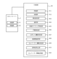
- Fig. 14 is a block diagram showing functions of an elevator system according to embodiment 5.
- the relay device 50 according to embodiment 5 includes a receiving unit 411 instead of the receiving unit 401, and a transmitting unit 312 instead of the transmitting unit 402.
- Other functions of the relay device 50 in Fig. 14 are similar to those of the second relay device in Fig. 11.
- the transmitting unit 21 of the robot server 2 has a function to transmit a usage request including information on the call of the robot 1 to the receiving unit 411 of the relay device 50, and a function to transmit a robot operation stop signal and a robot operation return signal to the receiving unit 411 of the relay device 50.
- the receiving unit 22 of the robot server 2 has a function to receive, from the transmitting unit 312 of the relay device 50, assigned car information that specifies the car 11 to which the call of the robot 1 is assigned.
- the receiving unit 411 of the relay device 50 has a function to receive a usage request and a robot operation stop signal from the transmitting unit 21 of the robot server 2, and a function to receive elevator information from the individual unit control devices 13.
- the receiving unit 411 of the relay device 50 has a function to receive elevator information from the individual unit control devices 13 of the corresponding unit every time the elevator information for that unit changes.
- the transmission unit 312 of the relay device 50 has a function of transmitting a registration request for a boarding floor car call for the assigned car selected by the selection unit 404 and a registration request for a destination floor car call for the assigned car to the corresponding car control device 13.
- the transmission unit 312 of the relay device 50 also has a function of transmitting information identifying the assigned car selected by the selection unit 404 to the reception unit 22 of the robot server 2.
- the functions of the transmitting unit 21 and the receiving unit 22 provided in the robot server 2 in the embodiments 1-5 may be provided in the robot 1.
- the second relay device 40 or the relay device 50 may communicate directly with the robot 1 without going through the robot server 2.
- Center Relay device 100 processing circuit, 100a processor, 100b memory, 100c dedicated hardware, 301 receiving unit, 302 transmitting unit, 312 transmitting unit, 401 receiving unit, 402 transmitting unit, 403 ranking setting unit, 404 selection unit, 405 transmission timing determination unit, 406 door opening determination unit, 407 robot operation determination unit, 408 evacuation floor selection unit, 409 elevator operation determination unit, 410 erroneous determination prevention unit, 411 receiving unit, 420 elevator information storage unit
Landscapes
- Engineering & Computer Science (AREA)
- Automation & Control Theory (AREA)
- Elevator Control (AREA)
Priority Applications (3)
| Application Number | Priority Date | Filing Date | Title |
|---|---|---|---|
| CN202280099950.7A CN119855775A (zh) | 2022-09-28 | 2022-09-28 | 电梯系统、中继装置、第二中继装置、中继方法以及计算机可读取的记录介质 |
| JP2024548913A JP7711851B2 (ja) | 2022-09-28 | 2022-09-28 | エレベーターシステム、中継装置、第二中継装置、中継方法、及びコンピュータ読み取り可能な記録媒体 |
| PCT/JP2022/036180 WO2024069797A1 (ja) | 2022-09-28 | 2022-09-28 | エレベーターシステム、中継装置、第二中継装置、中継方法、及びコンピュータ読み取り可能な記録媒体 |
Applications Claiming Priority (1)
| Application Number | Priority Date | Filing Date | Title |
|---|---|---|---|
| PCT/JP2022/036180 WO2024069797A1 (ja) | 2022-09-28 | 2022-09-28 | エレベーターシステム、中継装置、第二中継装置、中継方法、及びコンピュータ読み取り可能な記録媒体 |
Publications (1)
| Publication Number | Publication Date |
|---|---|
| WO2024069797A1 true WO2024069797A1 (ja) | 2024-04-04 |
Family
ID=90476630
Family Applications (1)
| Application Number | Title | Priority Date | Filing Date |
|---|---|---|---|
| PCT/JP2022/036180 Ceased WO2024069797A1 (ja) | 2022-09-28 | 2022-09-28 | エレベーターシステム、中継装置、第二中継装置、中継方法、及びコンピュータ読み取り可能な記録媒体 |
Country Status (3)
| Country | Link |
|---|---|
| JP (1) | JP7711851B2 (https=) |
| CN (1) | CN119855775A (https=) |
| WO (1) | WO2024069797A1 (https=) |
Cited By (1)
| Publication number | Priority date | Publication date | Assignee | Title |
|---|---|---|---|---|
| JP7708276B1 (ja) | 2024-07-17 | 2025-07-15 | 三菱電機ビルソリューションズ株式会社 | エレベーターシステム |
Citations (7)
| Publication number | Priority date | Publication date | Assignee | Title |
|---|---|---|---|---|
| JP2010023959A (ja) * | 2008-07-16 | 2010-02-04 | Fuji Heavy Ind Ltd | エレベータによる自律走行車の移動システム |
| JP2012018646A (ja) * | 2010-07-09 | 2012-01-26 | Murata Mach Ltd | 自律走行体移動システム |
| JP2020029322A (ja) * | 2018-08-21 | 2020-02-27 | 東芝エレベータ株式会社 | エレベータを用いた搬送システム、これに用いるエレベータ、およびエレベータ制御方法 |
| CN111170095A (zh) * | 2019-12-31 | 2020-05-19 | 北京猎户星空科技有限公司 | 一种电梯调度系统 |
| JP2020109039A (ja) * | 2019-01-07 | 2020-07-16 | 東芝エレベータ株式会社 | エレベータの制御システムおよび制御方法 |
| WO2021210186A1 (ja) * | 2020-04-18 | 2021-10-21 | 三菱電機株式会社 | 空気調和機動作システム、空気調和機およびサーバ |
| JP2022024765A (ja) * | 2020-07-28 | 2022-02-09 | 株式会社東芝 | 自律移動型ロボット及びプログラム |
Family Cites Families (1)
| Publication number | Priority date | Publication date | Assignee | Title |
|---|---|---|---|---|
| JP7231096B1 (ja) * | 2022-06-14 | 2023-03-01 | 三菱電機株式会社 | エレベーターシステム、中継装置、ビルシステム、中継方法、および中継プログラム |
-
2022
- 2022-09-28 WO PCT/JP2022/036180 patent/WO2024069797A1/ja not_active Ceased
- 2022-09-28 JP JP2024548913A patent/JP7711851B2/ja active Active
- 2022-09-28 CN CN202280099950.7A patent/CN119855775A/zh active Pending
Patent Citations (7)
| Publication number | Priority date | Publication date | Assignee | Title |
|---|---|---|---|---|
| JP2010023959A (ja) * | 2008-07-16 | 2010-02-04 | Fuji Heavy Ind Ltd | エレベータによる自律走行車の移動システム |
| JP2012018646A (ja) * | 2010-07-09 | 2012-01-26 | Murata Mach Ltd | 自律走行体移動システム |
| JP2020029322A (ja) * | 2018-08-21 | 2020-02-27 | 東芝エレベータ株式会社 | エレベータを用いた搬送システム、これに用いるエレベータ、およびエレベータ制御方法 |
| JP2020109039A (ja) * | 2019-01-07 | 2020-07-16 | 東芝エレベータ株式会社 | エレベータの制御システムおよび制御方法 |
| CN111170095A (zh) * | 2019-12-31 | 2020-05-19 | 北京猎户星空科技有限公司 | 一种电梯调度系统 |
| WO2021210186A1 (ja) * | 2020-04-18 | 2021-10-21 | 三菱電機株式会社 | 空気調和機動作システム、空気調和機およびサーバ |
| JP2022024765A (ja) * | 2020-07-28 | 2022-02-09 | 株式会社東芝 | 自律移動型ロボット及びプログラム |
Cited By (2)
| Publication number | Priority date | Publication date | Assignee | Title |
|---|---|---|---|---|
| JP7708276B1 (ja) | 2024-07-17 | 2025-07-15 | 三菱電機ビルソリューションズ株式会社 | エレベーターシステム |
| JP2026013619A (ja) * | 2024-07-17 | 2026-01-29 | 三菱電機ビルソリューションズ株式会社 | エレベーターシステム |
Also Published As
| Publication number | Publication date |
|---|---|
| CN119855775A (zh) | 2025-04-18 |
| JPWO2024069797A1 (https=) | 2024-04-04 |
| JP7711851B2 (ja) | 2025-07-23 |
Similar Documents
| Publication | Publication Date | Title |
|---|---|---|
| RU2317242C2 (ru) | Способ управления лифтовой установкой, а также лифтовая установка для его осуществления | |
| CN117262928B (zh) | 电梯系统、中继装置、楼宇系统、中继方法及存储介质 | |
| US20110147134A1 (en) | Method of handling passenger requests during elevator modernization | |
| CN110775744B (zh) | 多轿厢电梯以及多轿厢电梯控制方法 | |
| JP7359340B1 (ja) | エレベーターシステム及びエレベーターのかご割り当て方法 | |
| JP7711851B2 (ja) | エレベーターシステム、中継装置、第二中継装置、中継方法、及びコンピュータ読み取り可能な記録媒体 | |
| JP5113962B2 (ja) | ダブルデッキエレベータシステムの制御装置および制御方法 | |
| JP3073650B2 (ja) | ダブルデッキエレベーターの制御装置 | |
| JP2024083710A (ja) | エレベーター制御装置及びエレベーター制御方法 | |
| JP7063405B1 (ja) | 移動体の管理システムおよびエレベーター | |
| JP2024085617A (ja) | エレベータ制御装置、エレベータ制御方法およびプログラム | |
| CN110775745B (zh) | 多轿厢电梯以及多轿厢电梯控制方法 | |
| JP7435888B1 (ja) | エレベータ連携制御装置、エレベータシステム、エレベータ連携制御方法及びエレベータ連携制御プログラム | |
| JP6781299B1 (ja) | 昇降機制御方法、及び昇降機制御装置 | |
| JP7559880B1 (ja) | エレベータ連携制御装置、エレベータシステム、エレベータ連携制御方法及びエレベータ連携制御プログラム | |
| JP7708276B1 (ja) | エレベーターシステム | |
| JP7582531B1 (ja) | エレベーターの群管理システム、群管理方法及び群管理プログラム | |
| JP3428522B2 (ja) | ダブルデッキエレベーターの運行制御装置 | |
| JP3457873B2 (ja) | ダブルデッキエレベーターの群管理制御装置 | |
| CN116534686B (zh) | 电梯运力分配系统、电梯运力分配方法及电梯 | |
| JP2505645B2 (ja) | エレベ―タの制御装置 | |
| EP4368552B1 (en) | Detecting a probe request in a method and in a system for controlling an elevator car | |
| JP7563642B1 (ja) | 群管理制御システムおよび制御方法 | |
| JP2001354365A (ja) | エレベータの制御装置 | |
| EP3643662B1 (en) | Elevator system to direct passenger to tenant in building whether passenger is inside or outside building |
Legal Events
| Date | Code | Title | Description |
|---|---|---|---|
| 121 | Ep: the epo has been informed by wipo that ep was designated in this application |
Ref document number: 22960860 Country of ref document: EP Kind code of ref document: A1 |
|
| ENP | Entry into the national phase |
Ref document number: 2024548913 Country of ref document: JP Kind code of ref document: A |
|
| WWE | Wipo information: entry into national phase |
Ref document number: 202280099950.7 Country of ref document: CN |
|
| WWP | Wipo information: published in national office |
Ref document number: 202280099950.7 Country of ref document: CN |
|
| NENP | Non-entry into the national phase |
Ref country code: DE |
|
| 122 | Ep: pct application non-entry in european phase |
Ref document number: 22960860 Country of ref document: EP Kind code of ref document: A1 |