WO2024057804A1 - 電子ペン - Google Patents
電子ペン Download PDFInfo
- Publication number
- WO2024057804A1 WO2024057804A1 PCT/JP2023/029495 JP2023029495W WO2024057804A1 WO 2024057804 A1 WO2024057804 A1 WO 2024057804A1 JP 2023029495 W JP2023029495 W JP 2023029495W WO 2024057804 A1 WO2024057804 A1 WO 2024057804A1
- Authority
- WO
- WIPO (PCT)
- Prior art keywords
- section
- pen
- axial direction
- electronic pen
- knock
- Prior art date
- Legal status (The legal status is an assumption and is not a legal conclusion. Google has not performed a legal analysis and makes no representation as to the accuracy of the status listed.)
- Ceased
Links
Images








Classifications
-
- G—PHYSICS
- G06—COMPUTING OR CALCULATING; COUNTING
- G06F—ELECTRIC DIGITAL DATA PROCESSING
- G06F3/00—Input arrangements for transferring data to be processed into a form capable of being handled by the computer; Output arrangements for transferring data from processing unit to output unit, e.g. interface arrangements
- G06F3/01—Input arrangements or combined input and output arrangements for interaction between user and computer
- G06F3/03—Arrangements for converting the position or the displacement of a member into a coded form
- G06F3/041—Digitisers, e.g. for touch screens or touch pads, characterised by the transducing means
- G06F3/046—Digitisers, e.g. for touch screens or touch pads, characterised by the transducing means by electromagnetic means
-
- B—PERFORMING OPERATIONS; TRANSPORTING
- B43—WRITING OR DRAWING IMPLEMENTS; BUREAU ACCESSORIES
- B43K—IMPLEMENTS FOR WRITING OR DRAWING
- B43K24/00—Mechanisms for selecting, projecting, retracting or locking writing units
- B43K24/02—Mechanisms for selecting, projecting, retracting or locking writing units for locking a single writing unit in only fully projected or retracted positions
- B43K24/08—Mechanisms for selecting, projecting, retracting or locking writing units for locking a single writing unit in only fully projected or retracted positions operated by push-buttons
-
- B—PERFORMING OPERATIONS; TRANSPORTING
- B43—WRITING OR DRAWING IMPLEMENTS; BUREAU ACCESSORIES
- B43K—IMPLEMENTS FOR WRITING OR DRAWING
- B43K29/00—Combinations of writing implements with other articles
- B43K29/08—Combinations of writing implements with other articles with measuring, computing or indicating devices
-
- G—PHYSICS
- G06—COMPUTING OR CALCULATING; COUNTING
- G06F—ELECTRIC DIGITAL DATA PROCESSING
- G06F3/00—Input arrangements for transferring data to be processed into a form capable of being handled by the computer; Output arrangements for transferring data from processing unit to output unit, e.g. interface arrangements
- G06F3/01—Input arrangements or combined input and output arrangements for interaction between user and computer
- G06F3/03—Arrangements for converting the position or the displacement of a member into a coded form
-
- G—PHYSICS
- G06—COMPUTING OR CALCULATING; COUNTING
- G06F—ELECTRIC DIGITAL DATA PROCESSING
- G06F3/00—Input arrangements for transferring data to be processed into a form capable of being handled by the computer; Output arrangements for transferring data from processing unit to output unit, e.g. interface arrangements
- G06F3/01—Input arrangements or combined input and output arrangements for interaction between user and computer
- G06F3/03—Arrangements for converting the position or the displacement of a member into a coded form
- G06F3/033—Pointing devices displaced or positioned by the user, e.g. mice, trackballs, pens or joysticks; Accessories therefor
- G06F3/0354—Pointing devices displaced or positioned by the user, e.g. mice, trackballs, pens or joysticks; Accessories therefor with detection of two-dimensional [2D] relative movements between the device, or an operating part thereof, and a plane or surface, e.g. 2D mice, trackballs, pens or pucks
- G06F3/03545—Pens or stylus
-
- G—PHYSICS
- G06—COMPUTING OR CALCULATING; COUNTING
- G06F—ELECTRIC DIGITAL DATA PROCESSING
- G06F3/00—Input arrangements for transferring data to be processed into a form capable of being handled by the computer; Output arrangements for transferring data from processing unit to output unit, e.g. interface arrangements
- G06F3/01—Input arrangements or combined input and output arrangements for interaction between user and computer
- G06F3/03—Arrangements for converting the position or the displacement of a member into a coded form
- G06F3/033—Pointing devices displaced or positioned by the user, e.g. mice, trackballs, pens or joysticks; Accessories therefor
- G06F3/038—Control and interface arrangements therefor, e.g. drivers or device-embedded control circuitry
- G06F3/0383—Signal control means within the pointing device
-
- G—PHYSICS
- G06—COMPUTING OR CALCULATING; COUNTING
- G06F—ELECTRIC DIGITAL DATA PROCESSING
- G06F3/00—Input arrangements for transferring data to be processed into a form capable of being handled by the computer; Output arrangements for transferring data from processing unit to output unit, e.g. interface arrangements
- G06F3/01—Input arrangements or combined input and output arrangements for interaction between user and computer
- G06F3/03—Arrangements for converting the position or the displacement of a member into a coded form
- G06F3/041—Digitisers, e.g. for touch screens or touch pads, characterised by the transducing means
- G06F3/044—Digitisers, e.g. for touch screens or touch pads, characterised by the transducing means by capacitive means
-
- G—PHYSICS
- G06—COMPUTING OR CALCULATING; COUNTING
- G06F—ELECTRIC DIGITAL DATA PROCESSING
- G06F3/00—Input arrangements for transferring data to be processed into a form capable of being handled by the computer; Output arrangements for transferring data from processing unit to output unit, e.g. interface arrangements
- G06F3/01—Input arrangements or combined input and output arrangements for interaction between user and computer
- G06F3/03—Arrangements for converting the position or the displacement of a member into a coded form
- G06F3/041—Digitisers, e.g. for touch screens or touch pads, characterised by the transducing means
- G06F3/044—Digitisers, e.g. for touch screens or touch pads, characterised by the transducing means by capacitive means
- G06F3/0442—Digitisers, e.g. for touch screens or touch pads, characterised by the transducing means by capacitive means using active external devices, e.g. active pens, for transmitting changes in electrical potential to be received by the digitiser
Definitions
- the present invention relates to an electronic pen that is used together with a position detection device, and is provided with a knock-type mechanism that causes the pen tip to move in and out.
- electronic pens have been viewed as an extension of stationery, and there is a desire to modularize their internal structure so that they can be handled in the same way as refills (refills and cartridges) for ballpoint pens.
- a device in which the component parts of the position indicator inside the pen housing of an electronic pen are modularized and integrated and configured to be replaceable like a refill for a ballpoint pen will be referred to as an electronic pen cartridge. do.
- the applicant has constructed an electronic pen cartridge for an electronic pen so that it can be handled in the same way as a refill for a ballpoint pen, and the casing of a knock-type ballpoint pen for stationery can be used as it is as a pen casing for an electronic pen.
- a click-type electronic pen has already been proposed (see, for example, Patent Document 1 (Japanese Patent No. 5959038)).
- an electronic pen is also provided that includes an electronic eraser function section having the same configuration as the position instruction section for handwritten input in order to erase information input by hand on the position detection sensor using the position instruction section of the electronic pen.
- a position indicating section for writing input is disposed on one end of the cylindrical pen housing in the axial direction, and a position indicating section for writing input is provided on the other end of the cylindrical pen housing in the axial direction.
- a position indicating section constituting the electronic eraser function section is arranged.
- the position indicating section that constitutes the electronic eraser function section is provided on the side that performs the knock operation.
- the pushing pressure (load)
- the electronic eraser function section is difficult to use.
- An object of the present invention is to provide a position indicator that can solve the above problems.
- a cylindrical pen housing a first position indicating section disposed at one end in the axial direction within the pen housing; a second position indicating section disposed on the other end side in the axial direction within the pen housing; a knock cam mechanism driven by a load in the axial direction applied from the other end side in the axial direction; Equipped with The first position indicating section is disposed such that a distal end side for indicating the position can be moved out and retracted from an opening at the one end side in the axial direction of the pen housing by the knock cam mechanism section, The second position indicating section is disposed such that a distal end side that instructs the position is the other end side in the axial direction, When a pressure greater than the pressure applied to the tip side of the second position indicator when the second position indicator is used is applied from the other end in the axial direction, the knock cam An electronic pen is provided, comprising: an elastic member for causing the distal end side of the first position indicating section to protrude and retract from the opening by a
- the knock cam mechanism section is configured such that when the second position indicating section is used, a pressure greater than the pressure applied to the tip side that indicates the position is applied in the axial direction of the pen housing.
- This configuration includes an elastic member that allows the knock cam mechanism to cause the distal end side of the first position indicating section to protrude and retract from the first opening of the pen housing when a voltage is applied from the other end side.
- the tip side of the first position indicating section by the knock cam mechanism section is The second position indicating section is easy to use because the operation of moving it out and out of the opening can be prevented.
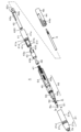
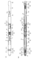
- FIG. 1 is a diagram for explaining an overview of a configuration example of an embodiment of an electronic pen according to the present invention.
- FIG. 2 is an exploded perspective view for explaining a configuration example of an electronic pen main body module constituting an embodiment of the electronic pen according to the present invention.
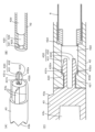
- FIG. 3 is a diagram for explaining a connecting portion of main components of the electronic pen main body module of the configuration example shown in FIG. 2;
- FIG. 3 is a diagram for explaining a configuration example of a first position indicating section and a second position indicating section in the embodiment of the electronic pen according to the present invention.
- FIG. 3 is a diagram for explaining a main part of a first position indicating section in an embodiment of an electronic pen according to the present invention.
- FIG. 3 is a diagram illustrating a main part of a first position indicating section and a main part of a pen housing in an embodiment of an electronic pen according to the present invention.
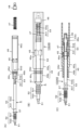
- FIG. 3 is a diagram for explaining an assembly procedure of an electronic pen main body module constituting an embodiment of an electronic pen according to the present invention.
- FIG. 3 is a diagram for explaining an assembly procedure of an electronic pen main body module constituting an embodiment of an electronic pen according to the present invention.
- FIG. 3 is a diagram for explaining an assembly procedure of an electronic pen main body module constituting an embodiment of an electronic pen according to the present invention.
- FIG. 3 is a diagram for explaining an assembly procedure of an electronic pen main body module constituting an embodiment of an electronic pen according to the present invention.
- FIG. 3 is a diagram for explaining an assembly procedure of an electronic pen main body module constituting an embodiment of an electronic pen according to the present invention.
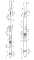
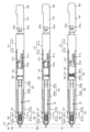
- FIG. 6 is a diagram for explaining a state in which the pen tip side of the first position indicating section is housed in the pen housing in the electronic pen main body module constituting the embodiment of the electronic pen according to the present invention.
- FIG. 6 is a diagram for explaining a state in which the pen tip side of the first position indicating section is extended from the opening of the pen housing in the electronic pen main body module constituting the embodiment of the electronic pen according to the present invention.
- FIG. 6 is a diagram for explaining the movement of the pen tip side during a knock operation of an example of a conventional knock-type electronic pen.
- FIG. 6 is a diagram for explaining the movement of the knock cam mechanism and the movement of the pen tip side during a knock operation of the electronic pen main body module constituting the embodiment of the electronic pen according to the present invention.
- FIG. 6 is a diagram for explaining the movement of the knock cam mechanism and the movement of the pen tip side during a knock operation of the electronic pen main body module constituting the embodiment of the electronic pen according to the present invention.
- FIG. 7 is a diagram for explaining another example of the main part of the first position indicating section in the embodiment of the electronic pen according to the present invention.
- FIG. 1 is a diagram for explaining an overview of an electronic pen 1 according to an embodiment.
- the first position indicating section has a configuration of a first electronic pen cartridge for writing input
- the second position indicating section has a second electronic pen cartridge to which an electronic eraser function is assigned.
- both the first position indicating section and the second position indicating section are of the electromagnetic induction type.
- a first electronic pen cartridge for writing input as an example of a first position indicating section is provided in the hollow part of the cylindrical pen housing 2.
- a second electronic pen cartridge to which an electronic eraser function is assigned as an example of a second position indicating section are arranged in the axial direction.
- the tip side of the first electronic pen cartridge becomes one end of the pen housing 2 in the axial direction
- the tip side of the second electronic pen cartridge becomes the other end of the pen housing 2 in the axial direction.
- a first electronic pen cartridge for handwritten input which is an example of the first position indicating section
- a second electronic pen to which an electronic eraser function is assigned which is an example of the second position indicating section.
- the cartridge will be referred to as an erasing cartridge.
- a writing input pen cartridge and an erasing cartridge arranged in the axial direction are combined in the knock cam mechanism, and a writing input is performed in response to a knocking operation that drives the knock cam mechanism.
- the tip side of the writing cartridge is configured to move in and out of the opening 2a on the pen tip side of the pen housing 2.
- a portion Nk of the knock cam mechanism that receives a knock operation (hereinafter referred to as a knock operation portion Nk) is in a state of protruding to the outside from the opening 2b on the rear end side of the pen housing 2.
- the distal end side of the erasing cartridge is configured to be located within the casing of the knock operation section Nk.
- FIG. 1(A) is a perspective view for explaining the appearance of the electronic pen 1 of this embodiment.
- the pen housing 2 of the electronic pen 1 of this embodiment is made of resin, for example, and includes a pen nib side housing part 21 that accommodates the pen nib side part of the writing input cartridge, and a rear end of the writing input cartridge.
- the side portion and the rear end side housing portion 22 (see FIG. 1(C)), which accommodates a portion including the erasing cartridge and the knock cam mechanism portion, are coupled in the axial direction.
- the rear end side housing portion 22 is made of a transparent material, and the inside thereof is shown in a visible state.
- FIG. 1(B) shows the modular component 3 in this embodiment, which includes a pen tip side housing section 21. As shown in FIG.
- this modular component 3 will be referred to as an electronic pen main body module 3.
- the pen tip side housing part 21 has a cylindrical structure, and one side in the axial direction thereof is a tapered part 2Aa having a gradually tapered structure, and the other side in the axial direction is an outer part.
- a cylindrical portion 21b having a diameter Ra equal to or slightly smaller than the inner diameter of the rear end side housing portion 22 is provided.
- the opening on the tapered tip side of the tapered portion 2Aa serves as the opening 2a of the pen housing 2 from which the tip side of the writing input cartridge protrudes in a retractable manner.
- an electronic pen configured by integrally combining a writing input cartridge, an erasing cartridge, and a knock cam mechanism part on the cylindrical part 21b side of the pen tip side housing part 21.
- the electronic pen main body module 3 is formed by combining the main body components 4.
- the rear end side housing part 22 has a cylindrical shape as shown in FIG. , as described above, is configured to be equal to or slightly larger than the outer diameter Ra of the cylindrical portion 21b of the pen tip side housing portion 21.
- the inner diameter Rb of the rear end side of the rear end side housing portion 22 is configured to be larger than the diameter Ra.
- the electronic pen main body module 3 is inserted into the hollow part of the rear end side housing part 22 from the electronic pen main body component 4 side, and the pen tip is inserted into the hollow part of the rear end side housing part 22.
- the electronic pen 1 shown in FIG. 1(A) is configured.
- the knock operation part Nk at the rear end of the electronic pen main body module 3 is inserted into the rear end housing, which is the opening 2b on the rear end side of the pen housing 2. It is in a state of protruding to the outside from an opening on the rear end side of the body portion 22 .
- ring-shaped grooves 21c and 21d are formed in the cylindrical part 21b of the pen tip side housing part 21, and grooves are formed in the inner wall of the rear end side housing part 22.
- Ring-shaped protrusions 22a and 22b are formed at positions corresponding to 21c and 21d.
- the outer shape of the rear end side housing portion 22 may be any shape as long as it can be easily gripped by the user. That is, the rear end side housing part 22 can be used as any cosmetic case as long as it has a configuration that can accommodate the electronic pen main body component 4 of the electronic pen main body module 3 and can be combined with the pen tip side housing part 21. It can be configured in the shape of
- the pen tip side housing part 21 and the rear end side housing part 22 are connected by press-fitting and a locking structure using a ring-shaped groove and a convex part, but the present invention is not limited to this.
- a threaded portion may be formed on the outer periphery of the pen tip side housing portion 21 and the inner wall surface of the rear end side housing portion 22, and the two may be screwed together.
- FIG. 2 is an exploded perspective view of the electronic pen main body module 3, showing the pen tip side housing part 21 and the electronic pen main body component 4 separately, and also shows a group of parts constituting the electronic pen main body component 4. It is shown broken down.
- the electronic pen main body component 4 connects the writing input cartridge 5, the erasing cartridge 6, the knock cam mechanism, the writing input cartridge 5, and the erasing cartridge in the axial direction. It consists of a group of parts that are made to move integrally in the axial direction in response to a knocking operation.
- the knock cam mechanism includes a cam main body, a rotor, a knock rod, and an elastic return member.
- the elastic return member is configured so that the pen tip side of the writing input cartridge 5 is removed from the outside through the pen tip side opening 2a of the pen housing 2 (in the following description, it may be referred to as the opening 2a of the pen tip side housing section 21). This is for returning the pen housing 2 from a protruding state to a state where it is housed inside the pen housing 2.
- the parts group includes a knock case part 41 which constitutes an example of a cam body part, a rear end shaft part 42 which constitutes an example of a knock rod part, a front shaft part 43 which constitutes an example of a rotor part, and a rear shaft part 42 which constitutes an example of a rotor part.
- a rear end cap member 44 whose end becomes a knock operation part Nk, a gear part 45, a gear holder part 46 that holds the gear part 45, a coil spring 47 that constitutes an elastic return member, and a spacer 48. Become.
- all of the parts in the parts group, except for the coil spring 47 are made of resin.
- the knock case part 41 has a cylindrical shape, in this example, a large diameter part 41a having an outer diameter equal to the above-mentioned diameter Ra, and an outer diameter slightly smaller than the inner diameter of the gear holder part 46.
- a small diameter portion 41b is provided.
- the small diameter portion 41b includes a plurality of groove portions 41c and a locking portion 41f that constitute a cam piece that engage with a plurality of wing portions 43a that constitute a cam piece of the front shaft portion 43 that constitutes an example of the rotor portion. is formed.
- the groove portion 41c engages with the wing portion 43a and locks when the pen tip side of the writing input cartridge 5 is housed in the pen tip side housing portion 21 without a knock operation being performed.
- the portion 41f engages with the feather portion 43a when the pen tip side of the writing input cartridge 5 is locked in a state protruding from the opening 2a of the pen tip side housing portion 21.
- the rear end shaft portion 42 is a member having a cylindrical shape, in this example, a cylindrical shape, and has an outer diameter smaller than the inner diameter of the knock case portion 41 having a cylindrical shape. , and is configured to be inserted from the rear end side.
- an axial protrusion 42a is provided at a predetermined angular position in the circumferential direction on the outer circumferential side of the rear end side shaft portion 42, and this protrusion 42a is formed in the hollow portion of the knock case portion 41.
- a groove not shown in FIG. 2
- a ring-shaped convex portion 42b is formed on the rear end side of the rear end shaft portion 42.
- the outer diameter of this ring-shaped protrusion 42b is set to a diameter Ra, and the rear end shaft part 42 is configured to be inserted into the knock case part 41 up to the position of this ring-shaped protrusion 42b. .
- the inner diameter of the hollow portion of the rear shaft portion 42 is configured to be larger than the outer diameter of the erasing cartridge 6, and the portion of the erasing cartridge 6 on the opposite side from the front end is It is configured so that it can be stored in the hollow part of the rear end side shaft part 42.
- the pen tip side end of the hollow part of the rear shaft part 42 has a smaller diameter than the outer diameter of the erasing cartridge 6, so that the erasing cartridge 6 can be moved from the rear shaft part 42 to the pen tip side. It is configured to remain within the rear end shaft portion 43 without moving forward.
- the length in the axial direction of the rear end shaft portion 42 is such that when the erasing cartridge 6 is stored in the hollow portion, the pen tip side of the erasing cartridge 6 extends from the rear end shaft portion 42.
- the length is such that it protrudes toward the rear end.
- the rear end cap member 44 is a cylindrical portion whose inner diameter is slightly larger than the outer diameter of the rear shaft portion 42 and whose outer diameter is selected to be equal to the diameter Ra, and whose rear end end is closed. .
- the rear end portion of the rear end cap member 44 is a knock operation portion Nk.
- the rear end shaft portion 42 includes a portion that protrudes further toward the rear end from the position of the ring-shaped convex portion 42b described above, and the rear end cap member 44 is placed on the protruding portion, so that it can be used for erasing.
- the leading end of the cartridge 6 is covered by a rear end cap member 44 .
- the rear end shaft portion 42 has an engaging convex portion 42c that protrudes further toward the rear end from the position of the ring-shaped convex portion 42b
- the rear end cap member 44 has an engaging convex portion 42c that protrudes further toward the rear end from the position of the ring-shaped convex portion 42b.
- a through window portion 44a into which the convex portion 42c fits is provided.
- the front shaft portion 43 which constitutes an example of the rotor portion, is arranged such that the side on which the plurality of wing portions (projections) 43a are formed is the small diameter portion 41b side of the knock case portion 41.
- the front shaft portion 43 has a cylindrical shape such that a plurality of wing portions 43a are engaged with the groove portion 41c of the small diameter portion 41b of the knock case portion 41 and become integral with the small diameter portion 41b.
- the wing portion 43a is provided on the knock case portion 41 side of the front shaft portion 43.
- the outer diameter of the front shaft part 43 is smaller than the inner diameter of the gear holder part 46, and the front shaft part 43 is movable in the axial direction within the gear holder part 46.
- On the pen tip side of the front shaft section 43 there is a serration that is held and provided in the gear holder section 46 and is engaged with a gear section 45, which will be described later, to rotate the front shaft section 43 by a predetermined angle.
- a gear portion 43b is formed.
- the front shaft part 43 is rotatably coupled to the rear end shaft part 42 inserted into the knock case part 41 with the axial direction being the rotation axis.
- a coupling protrusion 430 for coupling with the rear end shaft section 42 is formed at the tip of the small diameter section 41b of the front shaft section 43 on the knock case section 41 side.
- a fitting part 420 is formed on the pen tip side of the rear end shaft part 42 to which a coupling protrusion 430 of the front shaft part 43 is rotatably coupled.
- FIG. 3 is an enlarged view for explaining the joint portion between the rear end shaft portion 42 and the front shaft portion 43
- FIG. 3(A) is an enlarged perspective view of the front shaft portion 43
- FIG. ) is a vertical cross-sectional view of an enlarged perspective view of the rear-end shaft portion 42
- FIG. 3(C) is a vertical cross-sectional view of the rear-end shaft portion 42 and the front shaft portion 43 in a coupled state.
- the coupling protrusion 430 formed at the tip of the small diameter portion 41b of the front shaft portion 43 has a cylindrical member separated by a slit 433 including the centerline position thereof. It is composed of two protruding pieces 431 and 432 formed.
- the front shaft portion 43 is made of elastic resin, and the two protruding pieces 431 and 432 can be elastically displaced toward the slit 433 side.
- tapered bulges 431a and 432a are formed, as shown in FIG. 3(A).
- the tapered bulges 431a and 432a are formed so that the diameter gradually increases from the distal end side to the middle of the length in the axial direction of the coupling protrusion 430.
- Engagement step portions 431t and 431t are provided midway along the length in the direction.
- the rear end side shaft portion 42 has a fitting portion consisting of a small diameter hole portion 421 having a small diameter into which the coupling protrusion portion 430 is inserted, and a large diameter hole portion 422 having a larger diameter than the small diameter hole portion 421. 420 is provided.
- a step portion 423 is formed between the small diameter hole portion 421 and the large diameter hole portion 422, with which the protrusion pieces 431 and 432 of the coupling protrusion portion 430 engage.
- the front shaft part 43 and the rear shaft part 42 are connected, as shown in FIG. 3(C). 42 are combined. That is, when the tip of the coupling protrusion 430 of the front shaft part 43 is inserted into the small diameter hole 421 of the fitting part 420 of the rear shaft part 42, the two protrusion pieces forming the coupling protrusion 430 are inserted. 431 and 432 are displaced toward the slit 433 in a direction intersecting the axial direction, so that the coupling protrusion 430 is inserted into the small diameter hole 421 of the fitting part 420.
- the coupling protrusion 430 is pushed in so that the tapered bulges 431a and 432a of the two protrusion pieces 431 and 432 are inserted into the space of the large diameter hole 422 of the fitting part 420 of the rear end shaft part 42.
- the two protruding pieces 431 and 432 are in the state where they are located, they elastically return to their original states.
- the engagement step portions 431t and 432t of the tapered bulges 431a and 432a of the two protrusion pieces 431 and 432 of the coupling protrusion 430 are connected to the rear end shaft portion. 42, and the front shaft portion 43 and the rear end shaft portion 42 maintain a coupled state.
- the front shaft part 43 has a configuration in which movement in the rotational direction with the axial direction as the center of rotation is not restricted.
- the portion 43 is rotatable about the axial direction with respect to the rear end shaft portion 42 .
- the recess 43c in which the front shaft portion 43 is provided allows the spacer 48 coupled to the rear end side of the writing input cartridge 5 to be attached to the front shaft portion 43, as will be described later.
- This is a fitting recess for fitting.
- the gear section 45 is for rotating the front shaft section 43 by a predetermined angle by engaging with the front shaft section 43.
- the gear section 45 rotates the front shaft section 43 by a predetermined angle. constitutes a part.
- the gear holder part 46 is composed of a cylindrical body consisting of a large diameter part 46a and a small diameter part 46b, and is configured to fix and hold the gear part 45 at a predetermined position in the axial direction of the hollow part. has been done.
- the gear portion 45 is fixed and held within the large diameter portion 46a of the gear holder portion 46 at a position slightly closer to the pen tip side in the axial direction.
- the position of the gear part 45 in the axial direction within the gear holder part 46 is such that the tip side of the writing input cartridge 5 is housed in the pen tip side housing part 21 when not knocking, and when the knock operation is performed, the tip side of the writing input cartridge 5 is housed in the pen tip side housing part 21. It is selected so that it can protrude from the opening 2a at the tip of the housing section 21.
- the outer diameter of the large diameter portion 46a of the gear holder portion 46 is equal to the outer diameter of the cylindrical portion 21b of the pen tip side housing portion 21, and the inner diameter from the position where this gear portion 45 is held to the rear end side is as described above.
- the outer diameter of the small diameter portion 41b of the knock case portion 41 is slightly larger than that of the small diameter portion 41b.
- the pen tip side from the position where the gear part 45 of the large diameter part 46a is held is smaller than the diameter on the rear end side and is equal to or larger than the inner diameter of the small diameter part 46b. has been done.
- the gear portion 45 is disposed within the gear holder portion 46 in such a manner that it cannot move toward the pen tip side in the axial direction.
- the outer diameter of the small diameter portion 46b of the gear holder portion 46 is approximately equal to or slightly smaller than the inner diameter of the cylindrical portion 21b of the pen tip side housing portion 21, and the inner diameter is such that the rear end side of the writing input cartridge 5 can be inserted therein.
- the outer diameter of the writing input cartridge 5 is larger than that of the rear end side.
- the gear portion 45 has a ring shape, and the writing input cartridge 5 is configured to be inserted through the gear portion 45.
- the writing input cartridge 5 has its rear end side housed in the large diameter part 46a and small diameter part 46b of the gear holder part 46, and its tip side from the small diameter part 46b to the pen tip side housing part 21 side. It is arranged so that it protrudes.
- the writing input cartridge 5 is configured such that its rear end side is fitted into a spacer 48 via a coil spring 47.
- the spacer 48 is configured to be locked by being fitted into the recess 43c of the front shaft portion 43, so that the writing input cartridge 5 with the spacer 48 fitted to the rear end can be inserted into the spacer 43c. 48 is fitted into the recess 43c of the front shaft section 43, so that the writing input cartridge 5 is locked to the front shaft section 43 via the spacer 48.
- the outer diameter of the front shaft portion 43 is smaller than the inner diameter of the large diameter portion 46a of the gear holder portion 46, so the front shaft portion 43 is inserted into the large diameter portion 46a of the gear holder portion 46.
- the outer diameter of the small diameter portion 41b of the knock case portion 41 is selected to be equal to or slightly smaller than the inner diameter of the large diameter portion 46a of the gear holder portion 46, and the small diameter portion 41b of the knock case portion 41 is selected as the gear holder portion.
- a ring-shaped groove in the inner wall of the large diameter part 46a of the gear holder part 46 fits into the vicinity of the joint of the small diameter part 41b of the knock case part 41 with the large diameter part 41a.
- Ring-shaped convex portions 41d and 41e are formed so that the gear holder portion 46 and the knock case portion 41 are coupled and locked in the coupled state.
- the gear holder part 46 and the knock case part 41 are connected to the case (casing) of the electronic pen main body component 4 in this embodiment. ) constitute the part.
- the erasing cartridge 6 is housed in the rear shaft portion 42 coupled to the front shaft portion 43, and the rear cap member 44 is attached to the rear shaft portion 42. This constitutes the electronic pen main body component 4.
- the electronic pen main body component 4 configured as described above into the pen tip side housing portion 21, the electronic pen main body The component part 4 is combined with the pen tip side housing part 21, and the electronic pen main body module 3 described above is configured.
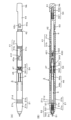
- FIG. 4(A) is a diagram showing a configuration example of the writing input cartridge 5 of the electronic pen 1 of this embodiment
- FIG. 4(B) is a diagram showing an example of the configuration of the writing input cartridge 5.
- FIG. 4(C) is an enlarged cross-sectional view of the elastic displacement portion 54 which is shown in FIG.
- the writing input cartridge 5 in the electronic pen 1 of this embodiment includes a core body 51, a signal transmission member 52, a cartridge housing 53, and, in this example, a cartridge housing 53. and an elastic displacement section 54 provided on the rear end side.
- the cartridge housing 53 includes a holder section 531 that holds the pen pressure detection section 55 and a circuit board 56 on which an electronic circuit is disposed, and a holder section 531 that holds the pen pressure detection section 55 and the circuit board 56 held by the holder section 531. and a protective cover part 532 that has the function of housing and protecting the.
- the core body 51 is made of a relatively hard and elastic resin material, such as POM (Polyoxymethylene). A portion 51a is formed.
- the signal transmission member 52 includes a coil 521 that constitutes a resonant circuit for transmitting and receiving signals to and from the position detection device using electromagnetic induction, and a magnetic core around which the coil 521 is wound, in this example a ferrite core 522. It is configured. A through hole 522a is formed in the ferrite core 522 in the axial direction.
- the diameter of the through hole 522a of this ferrite core 522 is made larger than the diameter of the axial center of the core 51, and the axial center of the core 51 is inserted through the through hole 522a to form a pen pressure detection section. 55 is fitted.
- the tip 51a of the core 51 is made to protrude beyond the ferrite core 522 as a pen tip, and the end 51b on the rear end side of the shaft center of the core 51 is configured to detect pen pressure. It is fitted into the section 55.
- the pressure (pen pressure) applied to the tip 51 a of the core 51 is applied to the pen pressure detection section 55 .
- the core body 51 is removably attached to the pen pressure detection section 55.
- the pen pressure detection unit 55 uses, for example, a mechanism that changes the capacitance of a variable capacitance capacitor according to the applied pressure (pen pressure) (see, for example, patent document (Japanese Patent Laid-Open No. 2011-186803)). configured.
- the pen pressure detection unit 55 may use a variable capacitor configured with a semiconductor chip made of a MEMS (Micro Electro Mechanical Systems) element (see, for example, patent document (Japanese Patent Application Laid-Open No. 2013-161307)).
- MEMS Micro Electro Mechanical Systems
- the circuit board 56 is mounted with electronic components such as a capacitor that forms a resonant circuit together with the coil 521, and in this example, a conductor pattern for connecting the pen pressure detection unit 55 configured as a variable capacitance capacitor to the resonant circuit. is formed.
- the holder portion 531 of the cartridge housing 53 is made of, for example, a resin material, and includes a cylindrical portion (not shown) that fits with the ferrite core 522 of the signal transmission member 52 and holds the pen pressure detection portion 55; It includes a circuit board mounting table (not shown) on which the circuit board 56 is mounted and held.
- the protective cover section 532 of the cartridge housing 53 is made of a pipe-shaped member made of a hard material, in this example, a pipe-shaped member made of metal.
- a circuit section protection member is configured to protect 56 electrical circuit components.
- the cartridge housing 53 is in such a state that a part of the cylindrical part that holds the pen pressure detection part 55 of the holder part 531 and the circuit board mounting base part are housed in the hollow part of the protective cover part 532. , a holder part 531 and a protective cover part 532 are coupled in the axial direction.
- the diameter of the cylindrical portion of the holder portion 531 and the diameter of the pipe-shaped member constituting the protective cover portion 532 are set to be the same diameter R0.
- the elastic displacement section 54 includes a coil spring 542 attached to a rod-shaped member 541 made of resin, for example, and which is thinner than the inner diameter of the protective cover section 532 of the cartridge housing 53.
- a rod-shaped member 541 made of resin, for example, and which is thinner than the inner diameter of the protective cover section 532 of the cartridge housing 53.
- one end 541a of the rod-shaped member 541 in the axial direction is inserted into the opening on the rear end side of the protective cover portion 532 of the cartridge housing 53. The sides are inserted and connected.
- the rod-shaped member 541 has a diameter that is smaller than the inner diameter of the protective cover portion 532 at one end 541a in the axial direction and slightly larger than the middle portion 541m into which the coil spring 542 is loosely fitted. Further, the other end 541b of the rod-shaped member 541 in the axial direction is configured to have a larger diameter than the intermediate portion 541m.
- a fitting protrusion 543 for fitting the writing input cartridge 5 into the recess 43c of the front shaft portion 43 is formed at the center of the circular end surface of the other end 541b.
- a ring-shaped member 544 is provided on one end 541a side of the middle portion 541m of the rod-shaped member 541.
- This ring-shaped member 544 has a portion whose outer diameter is approximately equal to or slightly smaller than the inner diameter of the opening on the rear end side of the protective cover portion 532 and a flange portion 544a that is equal to the outer diameter R0 of the protective cover portion 532. It is configured to be smaller than the outer diameter of one end 541a of the rod-shaped member 541 and larger than the middle portion 541m.
- the diameter of the coil spring 542 is selected to be larger than the diameter of the intermediate portion 541m of the rod-shaped member 541 and smaller than the diameter R0 of the protective cover portion 532 and the other end 541b of the rod-shaped member 541. Therefore, the coil spring 542 is attached to the intermediate portion 541m between the ring-shaped member 544 press-fitted into the opening on the rear end side of the protective cover portion 532 of the cartridge housing 53 and the other end 541b of the rod-shaped member 541. Retained. In this holding state, the coil spring 542 causes the ring-shaped member 544 on the rear end side of the protective cover portion 532 of the cartridge housing 53 and the other end 541b side of the rod-shaped member 541 to mutually move. It is in a state where it is elastically biased to separate them.
- the elastic displacement portion 54 configured as described above is inserted into the protective cover portion 532 from the opening on the rear end side of the protective cover portion 532 with one end portion 541a thereof, so that the elastic displacement portion 54 can be inserted into the protective cover portion 532 through the rear end side opening of the protective cover portion 532. Attached to the end. As a result, the elastic displacement portion 54 is attached in such a manner that the middle portion 541 m and the other end portion 541 b of the rod-shaped member 541 into which the coil spring 542 is loosely fitted are exposed to the outside of the protective cover portion 532 .
- the outer diameter of one end 541a of the rod-shaped member 541 is smaller than the inner diameter of the protective cover portion 532, and the middle portion 541m of the rod-shaped member 541 has a ring shape fixed to the protective cover portion 532.
- the member 544 is movable in the axial direction against the elastic biasing force of the coil spring 542.
- one end 541a side of the rod-shaped member 541 of the elastic displacement portion 54 is in a state where it can move toward the pen tip side within the hollow portion of the protective cover portion 532 against the elastic force of the coil spring 542.
- the writing input cartridge 5 as shown in FIG. 4(A) is formed. Then, a load of a predetermined value or more is applied to the writing input cartridge 5 to cause its length in the axial direction to contract against the elastic displacement force of the coil spring 542 of the elastic displacement section 54.
- the coil spring 542 of the elastic displacement part 54 is elastically contracted, one end 541a of the rod-shaped member 541 moves toward the pen tip inside the protective cover part 532, and the shaft of the writing input cartridge 5 is moved. It undergoes a displacement that causes the length in the cardiac direction to contract. When such a load disappears, the coil spring 542 returns elastically to expand, and the length of the writing input cartridge 5 in the axial direction returns to the original state shown in FIG. 4(A).
- the elastic characteristics of the coil spring 542 are insensitive to a load in the range of writing pressure applied to the tip 51a of the core body 51 when the electronic pen 1 is used. That is, the elastic characteristics of the coil spring 542 are insensitive to loads within the range of pen pressure values detected by the pen pressure detection section 55.
- the coil spring 542 is activated when the electronic pen 1 is used, and when a load due to a knocking operation by the user is applied, which is greater than the load in the writing pressure range applied to the tip 51a of the core body 51, or when the electronic pen 1 is used. It has elastic properties such that it expands and contracts as described above when an impact load or the like that is larger than the load in the writing pressure range is applied to 1. The latter expansion and contraction in response to an impact load means that the elastic displacement portion 54 plays the role of a so-called shock absorber for the writing input cartridge 5.
- the elastic displacement portion 54 is removable from the protective cover portion 532 of the writing input cartridge 5.
- the elastic characteristics of the coil spring 47 as the elastic return member in the knock cam mechanism described above are similar to those used in a general knock-type ballpoint pen, and the elastic force is higher than that of the coil spring 542 of the elastic displacement section 54. is small.
- a projecting portion 57 is provided that projects from the outer circumferential side of the cartridge housing 53 in a direction intersecting the axial direction, in this example, a direction perpendicular to the axial direction.
- the projecting portion 57 is provided on the holder portion 531 on the pen tip side of the cartridge housing 53.
- the projecting portion 57 is configured to project from the outer peripheral side surface of the holder portion 531 into a flange-like portion having a predetermined thickness.
- the projecting portion 57 may be configured integrally with the outer casing of the holder portion 531, or may be configured separately from the holder portion 531.
- the projecting portion 57 may be formed to project (protrude) over the entire circumference of the outer periphery of the holder portion 531 in a direction perpendicular to the axial direction; however, in this embodiment, as shown in FIG. 5, the holder portions 531 are shaped to protrude in a direction perpendicular to the axial direction from positions 180 degrees apart from each other by the width of the diameter of the holder portion 531.
- the tip of the overhanging portion 57 in the axial direction has an arcuate shape so as to follow the inner wall surface of the pen tip side housing portion 21 of the pen housing 2 .
- the contact area between the axial tip of the overhanging portion 57 and the inner wall surface of the pen tip side housing portion 21 of the pen housing 2 is minimized, so that it is possible to The writing input cartridge 5 can be easily moved in the axial direction within the pen housing 2 when receiving an impact load.
- the overhanging portion 57 is formed in the above-described shape, on the side of the overhanging portion 57 in the direction that intersects with the overhanging direction, the overhanging portion 57 and the pen tip side casing are A space is formed between the inner wall surface of the portion 21 and the inner wall surface of the portion 21 .
- a protrusion or a locking piece is provided in this space at the position of the protrusion 57 to prevent the writing input cartridge 5 from rotating around the axial direction within the pen housing 2. I have to.
- the end portion (lead portion) of the coil 521 is passed through this space to the holder portion 531 side without contacting the inner wall of the pen tip side housing portion 21. Note that the end portion of the coil 521 may be guided toward the holder portion 531 by providing a groove in the protruding portion 57 so as not to protrude outward from the groove portion.
- FIG. 6(A) is a sectional view of the pen tip side of the pen tip side housing part 21 of the pen housing 2
- FIG. 6(B) is a diagram showing the pen tip side of the writing input cartridge 5.
- the inner wall surface of the pen tip side housing part 21 is engaged with a protruding part 57 provided on the cartridge housing 53 of the writing input cartridge 5.
- a stepped portion 21s is formed as a stopper portion for preventing further movement of the writing input cartridge 5 toward the pen tip side of the pen tip side housing portion 21 of the pen housing 2. ing.
- the pen tip side of the writing input cartridge 5 protrudes to the outside from the opening 2a of the pen housing 2 (pen tip side opening of the pen tip side housing part 21).
- the desired length in the axial direction is predetermined in consideration of ease of input operation by the user.
- the projecting portion 57 provided on the cartridge housing 53 of the writing input cartridge 5 and the stepped portion 21s formed on the inner wall surface of the pen tip side housing portion 21 of the pen housing 2 are , the position in the axial direction so that when the protrusion length of the pen tip side of the writing input cartridge 5 from the opening 2a of the pen housing 2 reaches the above-mentioned prescribed protrusion length Lp, the two engage with each other. is defined and formed.
- the formation position of the protruding part 57 provided on the cartridge housing 53 of the writing input cartridge 5 in this embodiment and the formation position of the stepped part 21s formed on the inner wall surface of the pen tip side housing part 21 are as follows. The relationship will be further explained with reference to FIG.
- the writing input cartridge 5 includes a ferrite core 522 around which a coil 521 is wound around a holder portion 531 on the pen tip side of a cartridge housing 53 having an outer diameter of R0.
- the signal transmitting member 52 is attached, and the core body 51 is inserted through the through hole 522a of the ferrite core 522, and the pen pressure detection unit 55 (not shown in FIG. 6) is disposed in the holder part 531. is mated to.
- the outer diameter R1 of the ferrite core 522 is smaller than the outer diameter R0 of the cartridge housing 53.
- the outer diameter R2 of the portion around which the coil 521 is wound around the ferrite core 522 is equal to or smaller than the outer diameter R0 of the cartridge housing 53. That is, they are configured to have a relationship of R1 ⁇ R2 ⁇ R0.
- the diameter R3 of the opening 2a on the pen tip side of the pen tip side housing portion 21 is slightly larger than the outer diameter R1 of the ferrite core 522 of the writing input cartridge 5.
- the electronic pen 1 when used, not only the core body 51 but also a part of the ferrite core 522 is exposed to the outside through the opening 2a.
- the length from the tip of the tip part 51a of the core body 51 to a part of the ferrite core 522 on the pen tip side is the specified protrusion length Lp described above. It is determined that Further, as shown in FIG. 6(B), in the axial direction, from the tip of the tip 51a of the core 51, the pen tip of the protruding portion 57 of the holder portion 531 of the cartridge housing 53 of the writing input cartridge 5 is The length to the side end face is Lz.
- the inner diameter R4 of the hollow part of the pen tip communicating with the opening 2a of the pen tip side housing part 21 is slightly larger than the outer diameter R0 of the writing input cartridge 5.
- the coil 521 wound around the ferrite core 522 constituting the signal transmitting member 52 is configured so as not to come into contact with the inner wall surface of the pen tip side housing part 21 in the hollow part with the inner diameter R4.
- the hollow part 21e of the pen tip side housing part 21 has a diameter that gradually decreases from the part with the inner diameter R4 to the opening 2a with the diameter R3. It has a sharp taper. Therefore, if the coil 521 of the writing input cartridge 5 comes to be located in the tapered portion, there is a risk that the coil 521 may come into contact with the inner wall surface of the tapered portion.
- the length of the winding portion of 521 to the pen tip side end is the length from the tip of the opening 2a of the pen tip side housing section 21 to the pen tip side end of the inner diameter R4 via the tapered part. It is configured to be equal to L2.
- L3 the length of this diameter R4 of the hollow portion 21e of the pen tip side housing section 21 is exposed to the portion shown in FIG. 6(B).
- the coil 521 of the writing input cartridge 5 shown in FIG. Therefore, the coil 521 does not come into contact with the inner wall of the hollow portion 21e of the pen tip side housing portion 21. Therefore, the coil 521 is not subjected to unnecessary load due to contact, and can be coupled to the position detection sensor with stable magnetic flux by the signal transmission member 52.
- the diameter of the arcuate portion at the tip in the protruding direction of the protruding portion 57 formed on the holder portion 531 of the cartridge housing 53 of the writing input cartridge 5 is the same as that of the stepped portion 21s of the pen tip side housing portion 21.
- the diameter R6 is larger than the inner diameter R4 of the hollow portion on the pen tip side than the position, and is approximately equal to or slightly smaller than the inner diameter R5 of the pen tip side housing portion 21. In other words, they are configured to have the relationship R4 ⁇ R6 ⁇ R5.
- the protrusion 57 of the writing input cartridge 5 engages with the stepped portion 21s of the inner wall surface of the pen tip side housing 21, so that the writing input cartridge 5 , in the hollow portion of the pen housing 2, the pen tip is prevented from moving toward the pen tip side.
- a part of the pen tip-side core body 51 and ferrite core 522 of the writing input cartridge 5 extends from the opening 2a of the pen tip-side housing part 21 of the pen housing 2 by the specified protrusion length Lp. It can be in a state where it protrudes to the outside.
- the electronic pen 1 always maintains a state in which its pen tip side protrudes outward from the opening 2a by the prescribed protrusion length Lp, and the pen tip side of the writing input cartridge 5
- the coil 521 which is an example of a component that is not desired to come into contact with the inner wall surface of the side housing section 21, can be prevented from coming into contact with the inner wall surface of the pen tip side housing section 21.
- the diameter of the arc-shaped portion at the tip in the protruding direction of the protruding portion 57 provided on the writing input cartridge 5 is approximately equal to the inner diameter R5 of the pen tip side housing portion 21, or Since the diameter R6 is slightly small, displacement of the writing input cartridge 5 in the direction orthogonal to the axial direction is also suppressed. Therefore, even with this, the coil 521, which is an example of a component that should not be brought into contact with the inner wall surface of the pen tip side housing section 21 on the pen tip side of the writing input cartridge 5, can be removed from the inner wall surface of the pen tip side housing section 21. This can be done to prevent contact with the
- the protruding portion 57 of the writing input cartridge 5 engages with the stepped portion 21s of the inner wall surface of the pen tip side housing portion 21, so that the writing input cartridge 5
- the pen nib side is configured so that it does not protrude beyond the specified protrusion length Lp to the outside from the opening 2a of the pen nib side housing 21. Therefore, even when a knock operation is performed, the protrusion amount exceeding the specified protrusion length Lp does not protrude beyond the specified protrusion length Lp.
- the coil 521 which is an example of a component that should not be brought into contact with the inner wall surface of the pen tip side housing section 21 on the pen tip side of the writing input cartridge 5, is prevented from coming into contact with the inner wall surface of the pen tip side housing section 21. It can be prevented from coming into contact with the inner wall surface.
- FIG. 4(C) An example of the configuration of the erasing cartridge 6 in the electronic pen 1 of this embodiment is shown in FIG. 4(C).
- the erasing cartridge 6 of this example has the same configuration as the writing input cartridge 5 described above, except that the elastic displacement portion 54 on the rear end side and the projecting portion 57 are removed.
- the erasing cartridge 6 in the electronic pen 1 of this embodiment is explained by assigning reference numerals in the 60s to parts similar to the above-described writing input cartridge 5, as shown in FIG. 4(C). , a core body 61, a signal transmission member 62, and a cartridge housing 63.
- the cartridge housing 63 includes a holder section 631 that holds the pen pressure detection section 65 and a circuit board 66 on which an electronic circuit is arranged, and a holder section 631 that holds the pen pressure detection section 65 and the circuit board 66 held by the holder section 631. and a protective cover part 632 that has the function of housing and protecting the.
- the signal transmitting member 62 includes a coil 621 that constitutes a resonant circuit for transmitting and receiving signals to and from the position detection device using electromagnetic induction, and a magnetic core around which the coil 621 is wound, in this example a ferrite core 622. It is configured. A through hole 622a is formed in the ferrite core 622 in the axial direction. Then, the core body 61 is inserted through the through hole 522a and fitted into the pen pressure detection section 55. In this case, the tip 51a of the core 51 is made to protrude beyond the ferrite core 522 as a pen tip.
- the shaft part 42 is attached to the rear end side of the knock case part 41, and the front shaft part 43 is attached to the pen tip side. , respectively.
- the rear end shaft part 42 is housed in the knock case part 41 through the opening 41g on the rear end side of the knock case part 41, and the rear end shaft part 42 is
- the coupling protrusion 430 of the front shaft section 43 is fitted into the fitting section 420 of the front shaft section 43 to assemble the assembly part 101AS constituting the main part of the knock cam mechanism section, as shown in FIG. 7(B).
- the rear end shaft portion 42 is movable in the axial direction within the knock case portion 41 while being coupled to the front shaft portion 43.
- the length of the groove 41h of the knock case portion 41 in the axial direction is relatively long, and the protrusion 42a of the rear end shaft portion 42 is engaged with the groove 41a. In this state, it is configured to move in the axial direction at least by the stroke in the axial direction at the time of the knock operation.
- the writing input cartridge 5 is placed on the pen tip side of the gear holder section 46 in the axial direction, and the coil spring is placed on the rear end side. 47 and spacer 48 are arranged.
- FIG. 8(B) the rear end side of the writing input cartridge 5 is inserted into the hollow part of the gear holder part 46, and the ring-shaped gear part 45 is inserted. Then, the coil spring 47 is wound around the rear end side through which the gear part 45 is inserted, and the fitting protrusion 543 provided at the end of the elastic displacement part 54 is fitted into the fitting recess 48a of the spacer 48.
- FIG. 8C shows a state in which the fitting protrusion 543 of the elastic displacement part 54 of the writing input cartridge 5 and the spacer 48 are fitted.
- the outer circumferential portion of the small diameter portion 46b of the gear holder portion 46 has a ring-shaped convex portion 46c that fits into the groove of the pen tip side housing portion 21. and 46d are formed.
- the coil spring 47 for elastic return of the knock cam mechanism covers the elastic displacement part 54 of the writing input cartridge 5 and the rear end of the protective cover part 532, and the spacer 48 and gear It is arranged between the part where the part 45 is provided and the stepped part 46e of the inner wall of the gear holder part 46.
- the writing input cartridge 5 is movable in the axial direction within the hollow part of the gear holder part 46, but due to the presence of the coil spring 47 and the spacer 48, an assembly part 102AS is formed that does not fall off to the pen tip side. Ru.
- FIGS. 8(A), (B), and (C) are slightly different for convenience of explanation. The same applies to each of the following figures.
- an assembly part 101AS that constitutes the main part of the knock cam mechanism shown in FIG. 7B is placed on the rear end side of the assembly part 102AS shown in FIG. 8B. are arranged in the axial direction with the gear part 43b side of the front shaft part 43 facing the gear holder part 46 side.
- a pen nib side housing section is attached to the pen nib side of the assembled part 103AS shown in FIG. Place 21.
- the pen tip side of the assembly part 103AS is inserted into the pen tip side housing section 21, and the small diameter section 46b of the gear holder section 46 is further inserted.
- the ring-shaped convex parts 46c and 46d of the small diameter part 46b of the gear holder part 46 into the ring-shaped groove (not shown) formed on the inner wall surface of the pen tip side housing part 21. , and maintain the bonded state of both to form an assembled part 104AS shown in FIG. 10(B).
- the locked state between the ring-shaped convex parts 46c and 46d and the ring-shaped groove can be released by pulling the pen tip side housing part 21 in the direction of separating it from the assembly part 104AS in the axial direction.
- the erasing cartridge 6 and the rear end cap member 44 are arranged side by side on the rear end side of the assembly part 104AS shown in FIG. 10(B).
- the erasing cartridge 6 is inserted on the side opposite to the pen tip side into the rear end shaft portion 42 of the assembly part 104AS. Thereafter, the rear end cap member 44 is placed so as to cover the pen tip side of the erasing cartridge 6, and the engagement protrusion of the rear end shaft portion 42 is inserted into the through window portion 44a of the rear end cap member 44.
- the rear end cap member 44 is coupled to the rear end shaft portion 42 by fitting the portion 42c.
- the rear end side housing part 22 is combined with the pen tip side housing part 21 in a state where the rear end side of this electronic pen main body module 3 is stored.
- the electronic pen 1 of the embodiment is formed.
- This coupled state is maintained by fitting the fitting protrusions 22a and 22b on the inner wall of the rear end side housing part 22 into the ring-shaped grooves 21c and 21d of the pen tip side housing part 21.
- the state of connection between the pen tip side housing section 21 and the rear end side housing section 22 is achieved by separating them, so that the ring-shaped grooves 21c, 21d of the pen tip side housing section 21 and the rear end side housing section 21 are connected to each other.
- the fitting between the fitting protrusions 22a and 22b on the inner wall of the housing section 22 is released, and the housing section 22 can be separated.
- the rear end cap member 44 can be assembled by pulling it in the axial direction while releasing the fitting between the through window 44a of the rear end cap member 44 and the engagement protrusion 42c of the rear shaft part 42. It can be separated from component 104AS.
- the electronic pen 1 of the above-described embodiment can be manufactured by sequentially assembling each component for configuring the electronic pen 1 in the axial direction. Since no adhesive is used, it can be disassembled in the reverse order of the above steps. Therefore, if some parts, not just the writing cartridge 5 or the erasing cartridge 6, are damaged or have deteriorated over time, you can repair the electronic pen 1 by replacing only those parts. can do. That is, even if some parts fail, there is no need to replace the entire electronic pen 1, which is economical.
- the operation at the time of a knock operation is different from that of a writing instrument such as a knock-type ballpoint pen.
- the coil spring 542 of the elastic displacement section 54 works, and the projecting section 57 of the writing input cartridge 5 and the stepped section 21s inside the pen tip side housing section 21 are involved.
- the knock operation is possible in the electronic pen main body module 3 in a state where the rear end side housing part 22 is not attached, so in the following description, The operation of the electronic pen main body module 3 will be explained.
- FIG. 12A shows a state in which the pen tip side of the writing input cartridge 5 is housed in the pen tip side housing section 21 in the electronic pen main body module 3 of the electronic pen 1 of this embodiment.
- FIG. 12(B) shows a longitudinal sectional view thereof.
- the pen tip side of the writing input cartridge 5 is housed in the pen tip side housing section 21.
- the coil spring 47 for elastic return and the elastic displacement portion 54 are in the initial state, which is the most extended state.
- the projecting portion 57 of the writing input cartridge 5 and the stepped portion 21s of the inner wall surface of the pen tip side housing portion 21 are spaced apart from each other in the axial direction.
- FIG. 13A shows that in the electronic pen main body module 3 of the electronic pen 1 of this embodiment, the pen tip side of the writing input cartridge 5 protrudes outside from the opening 2a of the pen tip side housing section 21.
- FIG. 13(B) shows a longitudinal sectional view thereof.
- the wing portion 43a of the front shaft portion 43 of the electronic pen main body module 3 engages with the locking portion 41f of the small diameter portion 41b of the knock case portion 41, and as shown in FIG. 13(B), the pen tip side of the writing input cartridge 5 is held in a state protruding from the opening 2a of the pen tip side housing section 21.
- the elastic return coil spring 47 is in an elastically displaced state.
- the elastic displacement portion 54 is once elastically displaced during a knocking operation that causes the pen tip side of the writing input cartridge 5 to protrude from the opening 2a of the pen tip side housing portion 21. In the completed state, the original length has been restored.
- the projecting portion 57 of the writing input cartridge 5 and the stepped portion 21s of the inner wall surface of the pen tip side housing portion 21 are engaged, and the writing The amount by which the pen tip side of the input cartridge 5 protrudes from the opening 2a of the pen tip side housing portion 21 is a prescribed protrusion length Lp, which is a predetermined appropriate amount.
- the front shaft part 43 and the rear shaft part 42 are in a coupled state, so in the state where the pen tip side of the writing input cartridge 5 protrudes as shown in FIG. 13(B), , the rear end cap member 44 is in a locked state in the pushed state. Therefore, in this state, even when the rear end cap member 44 side is directed toward the position detection sensor side in order to use the erasing cartridge 6, the knock operation part Nk is free, as in a knock type ballpoint pen. It does not get stored away and is easy to use when instructing to erase.
- the pen tip side of the writing input cartridge 5 is inserted into the pen tip side housing part 21 by a knocking operation from the state shown in FIG. 13(B).
- the knock mechanism is designed not to operate at the pen pressure level in the case of . In this respect as well, it is easy to use the erase instruction using the erase cartridge 6.
- FIG. 14 is a diagram for explaining the movement of the pen tip side of the electronic pen main body 3PR during a knock operation of the conventional knock-type electronic pen 1PR.
- FIG. 14A shows a non-extended state in which the pen tip side of the electronic pen main body 3PR is housed in the pen housing 2PR.
- FIG. 14(B) shows that from the state of FIG. 14(A), the user of the electronic pen 1PR presses down the knock bar 12PR of the knock cam mechanism part 10PR and pushes the pen tip side of the electronic pen body part 3PR.
- FIG. 14 which shows a state in which the pen housing 2PR protrudes from the opening by a specified protrusion length Lp.
- the user further pushes in the knock bar 12PR to define the pen tip of the electronic pen body 3PR from the opening of the pen housing 2PR, as shown in FIG. 14(C).
- the protrusion length Lp or more is made to protrude.
- the rotor part of the knock cam mechanism part 10PR rotates, and as shown in FIG. 14(D), the pen tip part of the electronic pen body part 3PR protrudes from the opening of the pen housing 2A by a specified protrusion length Lp.
- the knock cam mechanism section 10PR is locked, and the feeding operation is completed.
- the knock bar 12PR is further pushed and the electronic pen 1PR is moved again as shown in FIG. 14(E).
- the rotor portion of the knock cam mechanism portion 10PR rotates to release the locked state of feeding, and the knock cam Due to the elastic displacement force of the return spring (not shown in FIG. 14, but corresponds to the coil spring 47) of the mechanism part 10PR, the electronic pen main body part 3PR moves as shown in FIG. 14(A), as shown in FIG. 14(F).
- the pen tip side of the electronic pen main body 3PR shown in 2 returns to the non-extended state stored in the pen housing 2PR.
- FIG. 15(A) shows a non-extended state in which the pen tip side of the writing input cartridge 5 is housed in the pen tip side housing section 21 of the pen housing 2 of the electronic pen main body module 3.
- the stepped portion 21s of the pen tip side housing portion 21 and the protruding portion 57 of the writing input cartridge 5 are spaced apart in the axial direction and are not in a state of engagement.
- the user of the electronic pen 1 moves the knock operation part Nk at the rear end of the rear end cap member 44 to the coil spring 47 as the return elastic member of the knock cam mechanism.
- the pen tip side of the writing input cartridge 5 was made to protrude by a specified protrusion length Lp from the opening 2a of the pen tip side housing section 21, as shown in FIG. 15(B).
- the stepped portion 21s of the pen nib side housing portion 21 and the protruding portion 57 of the writing input cartridge 5 engage with each other, and the pen nib side of the writing input cartridge 5 is no longer connected to the pen nib side housing. It is in a state in which it does not move within the body portion 21 in the direction of protruding from the opening 2a.
- the front shaft portion 43 constituting the rotor portion moves in the axial direction, and the wing portion 43a of the front shaft portion 43 moves toward the small diameter portion 41b of the knock case portion 41.
- the front shaft portion 43 and the gear portion 45 begin to engage with each other, and rotational force begins to be applied to the front shaft portion 43.
- the writing input cartridge 5 is in a state where the pen tip protrudes from the opening 2a of the pen tip side housing 21 by the specified protrusion length Lp. locked.
- the contracted elastic displacement portion 54 of the writing input cartridge 5 returns to its original length, and the electronic pen 1 extends the writing input cartridge 5 by the specified protrusion length Lp.
- the user enters a state in which writing input is performed by drawing out the pen tip, and the drawing out of the pen tip of the writing input cartridge 5 by the knocking operation is completed.
- the length in the axial direction that the pen tip side of the writing input cartridge 5 moves during the knocking operation is smaller than the length of the stroke in the axial direction (corresponding to the moving distance in the axial direction of the front shaft portion 43). . That is, the pen tip side of the writing input cartridge 5 moves by the same amount as the pushing amount of the knock operation part Nk until the protruding part 57 collides with the stepped part 21s of the pen tip side housing part 21. It will not move any further.
- the elastic displacement section 54 of the writing input cartridge 5 changes its length in the axial direction.
- the displacement of the length of the elastic displacement portion 54 becomes a part of the necessary stroke during the knock operation.
- the pen tip of this writing input cartridge 5 When the pen tip of this writing input cartridge 5 is extended from the opening 2a of the pen housing 2 (pen tip side housing part 21), for example, if the electronic pen 1 is accidentally dropped, the pen When an impact load is applied to the tip side, the impact load is absorbed by the elastic displacement of the elastic displacement portion 54, and damage to the writing input cartridge 5 can be avoided. That is, the elastic displacement portion 54 functions as a so-called shock absorber. Note that even when an impact load is applied to the rear end cap member 44 side, it similarly functions as a shock absorber.
- the front shaft part 43 rotates and moves away from the gear part 45.
- the wing portion 43a returns to the state shown in FIG. 15A in which it fits into the groove portion 41c of the knock case portion 41, and the tip of the writing input cartridge 5 returns to the state housed in the pen tip side housing portion 21. .
- the writing input cartridge 5 that is fed out by the knocking operation is prevented from being displaced in the direction perpendicular to the axial direction due to the presence of the protrusion 57.
- the coil 521 which is an example of a component that should not be brought into contact with the inner wall surface of the pen tip side housing section 21 on the side, can be prevented from coming into contact with the inner wall surface of the pen tip side housing section 21.
- the knock cam mechanism section is configured so that it does not operate unless pressure (load) resisting the elastic displacement force of the coil spring 542 of the elastic displacement section 54 is applied to the knock operation section Nk to push the rear end cap member 44. .
- the front shaft part 43 and the rear end shaft part 42 are in a coupled state, and the rear end cap member 44 including the knock operation part Nk is connected to the rear end shaft part 42. Since it is coupled to the side shaft portion 42, the rear end cap member 44 including the knock operation portion Nk is held at the position shown in FIG. 16(C). That is, the rear end cap member 44 does not move in the axial direction to freely go back and forth between the dotted line position and the solid line position like the knock bar 12PR in the state of the knock type ballpoint pen shown in FIG. 14(D). Therefore, it is possible to improve the inconvenience caused by the above-mentioned knock-type ballpoint pen.
- the electronic pen 1 of this embodiment can be assembled by sequentially fitting a plurality of parts in the axial direction, and can be easily disassembled by reversing the procedure. can. Therefore, each part can be replaced, which is highly economical.
- the front shaft portion 43 constituting the rotor portion and the rear end shaft portion 42 constituting the knock rod are connected to each other, but they do not have to be connected to each other as long as the rear end shaft portion 42 can press and move the front shaft portion 43 in the axial direction.
- the gear section 45 is used to rotate the front shaft section 43 as an example of the rotor section, but the structure for rotating the rotor section is limited to this example. Needless to say, it is not.
- the knock cam mechanism when using the erasing cartridge 6 of the electronic pen 1, the knock cam mechanism must be applied with a load greater than the load during a normal knock operation in the case of a conventional knock-type ballpoint pen, etc.
- the coil spring 47 of the knock cam mechanism and the coil spring 542 of the elastic displacement part 54 of the writing input cartridge 5 are used, and the protruding part 57 and the pen tip side housing part 21 are used.
- the configuration uses engagement with the step portion 21s, the configuration is not limited to this.
- the elastic displacement part 54 is removed from the writing input cartridge 5, and the overhang part 57 and the stepped part 21s are not provided.
- This structure also allows the knock cam mechanism to operate when using the erasing cartridge 6 of the electronic pen 1 unless a load greater than the load applied during normal knock operation in the case of a conventional knock-type ballpoint pen is applied. It is possible to configure a configuration that prevents this from occurring.
- the stopper part on the inner wall surface of the pen-nib side housing part 21 that engages with the overhang part 57 to prevent the writing input cartridge 5 from moving toward the pen-nib side is
- the stepped portion 21s is formed by changing the diameter of the hollow portion of the pen tip side housing portion 21, the present invention is not limited to such a stepped portion 21s. Any type of material may be used as long as it can prevent the writing input cartridge 5 from moving toward the pen tip.
- the stopper portion is a protrusion that engages with all or part of the protruding portion 57 on the inner wall surface of the pen tip side housing portion 21 to prevent the writing input cartridge 5 from moving toward the pen tip side. It may also be a configuration.
- the protruding portion 57 provided on the writing input cartridge 5 was arranged to protrude in a direction perpendicular to the axial direction of the cartridge housing 53, but it is limited to the perpendicular direction. Instead, it may be any direction as long as it is in a direction intersecting the axial direction and engages with the stepped portion 21s of the pen tip side housing portion 21. Considering this case, when determining the formation position of the step portion 21s and the formation position of the overhang portion 57, the selection is made based on the engagement position between the step portion 21s and the overhang portion 57.
- the projecting portions 57 are formed to protrude from the angular ranges that differ by 180 degrees from each other on the outer periphery of the cartridge housing 53; It may be formed so as to protrude in three directions from the corner range, or one projecting part may be formed over a predetermined corner range on the outer periphery of the cartridge housing 53.
- the protruding portion 57 may be formed over the entire circumference of the cartridge housing 53.
- FIG. 17 shows an example in which an overhang is formed around the entire circumference of the cartridge housing 53.
- the overhang is formed by devising the shape of the holder portion 531 of the cartridge housing 53. This is an example.
- FIG. 17(A) is an enlarged view of the holder portion 531A of the cartridge housing 53A in this example on the side connected to the signal transmitting member 52 made of a coil 521 wound around a ferrite core 522.
- FIG. 17(B) is an enlarged perspective view of the signal transmitting member 52 including the coil 521 wound around the ferrite core 522 and the holder portion 531A of the cartridge housing 53A.
- the holder portion 531A of the cartridge housing 53A has an outer diameter equal to the outer diameter R0 of the protective cover portion 532 at the position where it is connected to the pen tip side end portion of the protective cover portion 532.
- the outer diameter of the holder portion 531A gradually increases from the outer diameter R0 at the joining position with the protective cover portion 532 toward the pen tip side, and the maximum outer diameter is the hollow portion 21e of the pen tip side housing portion 21.
- It has an overhang-shaped portion 57A having a diameter R6 that is approximately equal to or slightly smaller than the inner diameter R5 of the inner diameter R5.
- a tip portion 531Aa having an outer diameter equal to the outer diameter R0 of the protective cover portion 532 is formed closer to the pen tip than the protruding portion 57A.
- a stepped portion is generated at the boundary between the end of the protruding shape portion 57A on the pen tip side and the tip portion 531Aa, and this stepped portion is An end surface 57Aa of the constituting projecting shape portion 57A engages with the step portion 21s of the pen tip side housing portion 21.
- the holder portion 531A is formed so as to have only the overhanging portion 57A without providing the tip portion 531Aa, and the end surface 57Aa of the overhanging portion 57A is a stopper portion on the inner wall surface of the pen tip side housing portion 21. It may be configured to engage with the stepped portion 21s, which is an example of the above.
- a recess 57Ab is provided at a predetermined angular position in the circumferential direction of the protruding portion 57A of the holder portion 531A.
- a protrusion that engages with the recess 57Ab is formed at a predetermined angular position in the circumferential direction of the inner wall surface near the stepped portion 21s of the pen tip side housing portion 21.
- a groove 57Ac is formed along the axial direction at a predetermined angular position in the circumferential direction on the outer peripheral surface of the protruding portion 57A of the holder portion 531A.
- the lead portions 521a and 521b at both ends of the coil 521 are housed in this groove 57Ac and are led into the protective cover portion 532.
- Inside the protective cover portion 532 is a circuit board held by the holder portion 531A, and the lead portions 521a and 521b of the coil 521 are connected to a capacitor arranged on this circuit board to form a resonant circuit.
- the elastic displacement portion 54 of the writing input cartridge 5 is provided on the rear end side of the cartridge housings 53 and 53A, but it may be provided in the middle of the cartridge housings 53.
- the protective cover portion 532 of the cartridge housing 53, 53A may be divided into two parts, and the protective cover part 532 may be provided in the middle thereof.
- the pen tip of the first position indicating section for writing input is configured to leave a writing mark on a writing medium such as paper
- the tip of the knock part NK on the rear end side is configured to leave a writing mark on a writing medium such as paper.
- An erasing function unit for erasing the handwritten marks may be provided.
- the core of the writing input cartridge 5 constituting the first position indicating part is made of a material containing graphite, for example, and the knock part NK on the rear end side is made of a material containing graphite.
- An eraser member may be provided at the tip of the graphite for erasing the handwritten marks made with the graphite.
- the first position indicating section was configured for writing input, and the second position indicating section was configured for erasing. Both of the instruction parts may be configured for written input.
- the first position indicating section and the second position indicating section are configured as electronic pen cartridges, but either or both may be configured as other than electronic pen cartridges.
- the electronic pen can be assembled by sequentially connecting multiple parts, and the assembled product can be uncoupled in the reverse order of the assembly process.
- a special configuration that can be easily separated into a plurality of parts has been adopted, but it goes without saying that the configuration is not limited to this.
- the invention is not limited to the electromagnetic induction type, and may also be applied to a capacitive type electronic pen such as an active capacitance type. , is similarly applicable.
- the first position indicating section and/or the second position indicating section can be configured as an electronic pen cartridge.
Landscapes
- Engineering & Computer Science (AREA)
- Theoretical Computer Science (AREA)
- General Engineering & Computer Science (AREA)
- Physics & Mathematics (AREA)
- Human Computer Interaction (AREA)
- General Physics & Mathematics (AREA)
- Electromagnetism (AREA)
- Mechanical Pencils And Projecting And Retracting Systems Therefor, And Multi-System Writing Instruments (AREA)
Abstract
Description
筒状のペン筐体と、
前記ペン筐体内の軸心方向の一端側に配設される第1の位置指示部と、
前記ペン筐体内の軸心方向の他端側に配設される第2の位置指示部と、
前記軸心方向の他端側から印加される前記軸心方向の荷重により駆動されるノックカム機構部と、
を備え、
前記第1の位置指示部は、位置指示を行う先端側が、前記ノックカム機構部により前記ペン筐体の軸心方向の前記一端側の開口から出没可能となるように配設されており、
前記第2の位置指示部は、位置指示を行う先端側が、前記軸心方向の前記他端側となる状態で配設されており、
前記第2の位置指示部の使用時に前記第2の位置指示部の前記先端側に印加される圧力よりも大きい圧力が、前記軸心方向の前記他端側から印加されたときに、前記ノックカム機構部により前記第1の位置指示部の前記先端側を前記開口から前記出没させるようにするための弾性部材を備える
ことを特徴とする電子ペンを提供する。
図1は、実施形態の電子ペン1の概要を説明するための図である。この例の電子ペン1は、第1の位置指示部が筆記入力用の第1の電子ペンカートリッジの構成を備えると共に、第2の位置指示部は、電子消しゴム機能が割り当てられた第2の電子ペンカートリッジの構成を備える。そして、この実施形態では、第1の位置指示部及び第2の位置指示部は、共に、電磁誘導方式の場合としている。
図2は、電子ペン本体部モジュール3の分解斜視図であり、ペン先側筐体部21と電子ペン本体構成部4を分離して示すと共に、電子ペン本体構成部4を構成する部品群を分解して示している。
図4(A)は、この実施形態の電子ペン1の筆記入力用カートリッジ5の構成例を示す図であり、また、図4(B)は、この筆記入力用カートリッジ5の後端側に設けられている弾性変位部54の拡大断面図であり、さらに、図4(C)は、消去用カートリッジ6の構成例を示す図である。
この実施形態の電子ペン1における筆記入力用カートリッジ5は、図4(A)に示すように、芯体51と、信号送信用部材52と、カートリッジ筐体53と、この例ではカートリッジ筐体53の後端側に設けられる弾性変位部54とからなる。カートリッジ筐体53は、筆圧検出部55を保持すると共に電子回路が配設される回路基板56を保持するホルダー部531と、ホルダー部531に保持される筆圧検出部55と回路基板56とを収納して保護する機能を備える保護カバー部532とからなる。
この実施形態の電子ペン1における消去用カートリッジ6の構成例を、図4(C)に示す。この例の消去用カートリッジ6は、上述した筆記入力用カートリッジ5から、後端側の弾性変位部54を取り除くと共に、張出部57を取り除いたものと同様の構成を有する。
以上のような構成を有する、この実施形態の電子ペン本体部モジュール3は、上述した部品を順次に組み上げてゆくことで、組み立てることができる。以下、この実施形態の電子ペン本体部モジュール3の組立手順について、図7~図11を参照して説明する。
この実施形態の電子ペン1においては、筆記具のノック式ボールペンなどと同様に、筆記入力用カートリッジ5による筆記入力を行うときには、後端キャップ部材44の後端部のノック操作部Nkを押下操作(ノック操作)して、筆記入力用カートリッジ5のペン先を、ペン筐体2のペン先側筐体部21の開口2aから突出させるようにする。そして、当該筆記入力用カートリッジ5のペン先がペン筐体2のペン先側筐体部21の開口2aから突出している状態から、さらにノック操作をすることで、筆記入力用カートリッジ5のペン先がペン先側筐体部21内に収容されて保護される元の状態に戻るように動作する。
以上説明したように、この実施形態の電子ペン1においては、電子ペン1におけるノック操作においては、ペン先側筐体部21の段部21sと筆記入力用カートリッジ5の張出部57とを係合させて、筆記入力用カートリッジ5のペン先側は、規定突出長Lpよりも突出しない状態を維持しつつ、弾性変位部54の弾性変位により、ノックカム機構部による筆記入力用カートリッジ5のペン先部の繰り出し及び復帰動作を可能としている。
なお、上述の実施形態の電子ペン1においては、回転子部を構成するフロントシャフト部43と、ノック棒を構成する後端側シャフト部42とを結合するようにしたが、フロントシャフト部43を後端側シャフト部42が軸心方向に押下移動させることができる構成であれば、結合しなくてもよい。
Claims (21)
- 筒状のペン筐体と、
前記ペン筐体内の軸心方向の一端側に配設される第1の位置指示部と、
前記ペン筐体内の軸心方向の他端側に配設される第2の位置指示部と、
前記軸心方向の他端側から印加される前記軸心方向の荷重により駆動されるノックカム機構部と、
を備え、
前記第1の位置指示部は、位置指示を行う先端側が、前記ノックカム機構部により前記ペン筐体の軸心方向の前記一端側の開口から出没可能となるように配設されており、
前記第2の位置指示部は、位置指示を行う先端側が、前記軸心方向の前記他端側となる状態で配設されており、
前記第2の位置指示部の使用時に前記第2の位置指示部の前記先端側に印加される圧力よりも大きい圧力が、前記軸心方向の前記他端側に印加されたときに、前記ノックカム機構部により前記第1の位置指示部の前記先端側を前記開口から前記出没させるようにするための弾性部材を備える
ことを特徴とする電子ペン。 - 前記ノックカム機構部は、前記第1の位置指示部の前記先端側が前記開口から突出する状態から、前記ペン筐体内に収納される状態に復帰するようにするための弾性復帰用部材を備え、
前記弾性部材は、前記弾性復帰用部材で構成されている
ことを特徴とする請求項1に記載の電子ペン。 - 前記ノックカム機構部は、カム本体部と、ノック棒部と、回転子部とを備え、
前記ノック棒部と前記回転子部とは、前記ペン筐体内において、軸心方向に結合されており、
前記第1の位置指示部の軸心方向の前記先端側とは反対側が前記回転子部に対して係止されると共に、前記ノック棒部に前記第2の位置指示部が配設されている
ことを特徴とする請求項1に記載の電子ペン。 - 前記ノックカム機構部は、前記第1の位置指示部の前記先端側が、前記開口から突出する状態から、前記ペン筐体内に収納される状態に復帰するようにするための弾性復帰用部材を備え、
前記第1の位置指示部は、使用時に前記先端側に印加される圧力の範囲では不感であって、前記圧力の範囲よりも大きい荷重が印加された場合に、前記印加された荷重に応じて、前記第1の位置指示部又は前記第2の位置指示部の軸心方向の長さを弾性的に収縮変位させる弾性変位部を備えており、
前記第1の位置指示部の前記軸心方向の所定位置には、前記軸心方向に交差する方向に突出する張出部が形成され、
前記ペン筐体の前記中空部の内壁面には、前記第1の位置指示部の前記先端側が前記ペン筐体の前記開口から外部に露出する状態において、前記張出部と係合して、前記ペン筐体内において、前記位置指示部の前記先端側への移動を阻止するストッパ部が形成され、
前記弾性部材は、前記弾性復帰用部材と前記弾性変位部とで構成される
ことを特徴とする請求項1に記載の電子ペン。 - 前記ノックカム機構部は、カム本体部と、ノック棒部と、回転子部とを備え、
前記ノック棒部と前記回転子部とは、前記ペン筐体内において、軸心方向に結合されており、
前記第1の位置指示部の軸心方向の前記先端側とは反対側が前記回転子部に対して係止されると共に、前記ノック棒部に前記第2の位置指示部が配設されている
ことを特徴とする請求項4に記載の電子ペン。 - 前記弾性復帰用部材は、前記ペン筐体内の前記第1の位置指示部が収納される中空部における前記軸心方向の所定の位置と、前記回転子との間に配設される
ことを特徴とする請求項5に記載の電子ペン。 - 前記弾性変位部は、前記第1の位置指示部に対して、前記軸心方向において、前記先端側とは反対側に設けられている
ことを特徴とする請求項4に記載の電子ペン。 - 前記弾性変位部は、前記第1の位置指示部に対して、前記軸心方向において、前記先端側とは反対側の端部に設けられ、
前記弾性変位部には、前記回転子部に対して嵌合されて係止する嵌合部が設けられている
ことを特徴とする請求項5に記載の電子ペン。 - 前記張出部は、前記第1の位置指示部の、前記先端側の先端位置から前記段部と係合する前記張出部の部分までの前記軸心方向における長さが、前記ペン筐体の前記先端側の先端位置から前記段部までの軸心方向の長さに、前記第1の位置指示部の前記先端側が、電子ペンの使用時に前記ペン筐体の前記開口から突出すべきとして設定された前記軸心方向の長さを加えた長さとなるように配設されている
ことを特徴とする請求項4に記載の電子ペン。 - 前記第1の位置指示部の前記先端側を、前記ペン筐体の前記第1の開口から突出させる際における前記ノックカム機構部のノック操作の際の前記軸心方向のストロークの長さよりも、前記第1の位置指示部の前記先端部が前記ノック操作の際に移動する前記軸心方向の長さが小さくされている
ことを特徴とする請求項4に記載の電子ペン。 - 前記第1の位置指示部の前記先端側を、前記ペン筐体の前記開口から突出させる際においては、前記第1の位置指示部の前記張出部が前記ペン筐体の前記ストッパ部と係合するまでは、前記弾性復帰用部材の弾性変位力に抗する圧力により前記ノックカム機構部は動作し、前記第1の位置指示部の前記張出部が前記ペン筐体の前記ストッパ部と係合した後には、前記弾性変位部の弾性変位力に抗する圧力により前記ノックカム機構部は動作する
ことを特徴とする請求項4に記載の電子ペン。 - 前記回転子部は、前記ノック棒部の前記第1の位置指示部の前記先端側への移動に応じて前記軸心方向に移動すると共に、前記カム本体部のカム片と係合するものであり、
前記ペン筐体内において、前記回転子部の前記第1の位置指示部の先端部側の端部と係合するような前記軸心方向の所定の位置には、前記回転子部が係合したときに、前記回転子部を所定の角度分回転させるギア部を備える
ことを特徴とする請求項4に記載の電子ペン。 - 前記ノックカム機構部は、カム本体部と、ノック棒部と、回転子部とを備え、
前記ノック棒部は、筒状体を備えており、前記第2の位置指示部の少なくとも前記先端側とは反対側の部分が前記筒状体内に収納されている、
ことを特徴とする請求項1に記載の電子ペン。 - 前記第2の位置指示部の前記先端側は、筒状部で覆われている
ことを特徴とする請求項13に記載の電子ペン。 - 前記第2の位置指示部の前記先端側は、キャップ状部材により覆われている
ことを特徴とする請求項1に記載の電子ペン。 - 前記第1の位置指示部は、筆記入力用あるいは描画入力用とされると共に、前記第2の位置指示部は、前記第1の位置指示部による筆記入力あるいは描画入力の消去用とされる
ことを特徴とする請求項1に記載の電子ペン。 - 前記第1の位置指示部及び前記第2の位置指示部は、電磁誘導方式の構成を備える
ことを特徴とする請求項1に記載の電子ペン。 - 前記第1の位置指示部及び前記第2の位置指示部は、アクティブ静電容量方式の構成を備える
ことを特徴とする請求項1に記載の電子ペン。 - 前記第1の位置指示部は、筒状の筐体内に配設されている電子回路と、位置検出センサとインタラクションを行うインタラクション部とがモジュール化されたカートリッジの構成とされている
ことを特徴とする請求項1に記載の電子ペン。 - 前記第2の位置指示部は、筒状の筐体内に配設されている電子回路と、位置検出センサとインタラクションを行うインタラクション部とがモジュール化されたカートリッジの構成とされている
ことを特徴とする請求項1に記載の電子ペン。 - 前記ストッパ部は、前記ペン筐体の内壁面に形成された段部の構成とされている
ことを特徴とする請求項4に記載の電子ペン。
Priority Applications (3)
| Application Number | Priority Date | Filing Date | Title |
|---|---|---|---|
| CN202380050915.0A CN119487482A (zh) | 2022-09-14 | 2023-08-15 | 电子笔 |
| JP2024546787A JPWO2024057804A1 (ja) | 2022-09-14 | 2023-08-15 | |
| US19/073,895 US20250208724A1 (en) | 2022-09-14 | 2025-03-07 | Electronic pen |
Applications Claiming Priority (2)
| Application Number | Priority Date | Filing Date | Title |
|---|---|---|---|
| JP2022146185 | 2022-09-14 | ||
| JP2022-146185 | 2022-09-14 |
Related Child Applications (1)
| Application Number | Title | Priority Date | Filing Date |
|---|---|---|---|
| US19/073,895 Continuation US20250208724A1 (en) | 2022-09-14 | 2025-03-07 | Electronic pen |
Publications (1)
| Publication Number | Publication Date |
|---|---|
| WO2024057804A1 true WO2024057804A1 (ja) | 2024-03-21 |
Family
ID=90274935
Family Applications (1)
| Application Number | Title | Priority Date | Filing Date |
|---|---|---|---|
| PCT/JP2023/029495 Ceased WO2024057804A1 (ja) | 2022-09-14 | 2023-08-15 | 電子ペン |
Country Status (4)
| Country | Link |
|---|---|
| US (1) | US20250208724A1 (ja) |
| JP (1) | JPWO2024057804A1 (ja) |
| CN (1) | CN119487482A (ja) |
| WO (1) | WO2024057804A1 (ja) |
Citations (3)
| Publication number | Priority date | Publication date | Assignee | Title |
|---|---|---|---|---|
| JP2018097458A (ja) * | 2016-12-09 | 2018-06-21 | 株式会社ワコム | 電子ペン |
| JP2019105907A (ja) * | 2017-12-11 | 2019-06-27 | 株式会社ワコム | 電子ペン及び電子ペン本体部 |
| WO2021200521A1 (ja) * | 2020-03-31 | 2021-10-07 | 株式会社ワコム | ノック式電子ペン |
Family Cites Families (2)
| Publication number | Priority date | Publication date | Assignee | Title |
|---|---|---|---|---|
| TWI736580B (zh) * | 2016-04-22 | 2021-08-21 | 日商和冠股份有限公司 | 電子筆及電子筆本體部 |
| JP7084127B2 (ja) * | 2017-09-01 | 2022-06-14 | 三菱鉛筆株式会社 | 入力タッチペン |
-
2023
- 2023-08-15 CN CN202380050915.0A patent/CN119487482A/zh active Pending
- 2023-08-15 WO PCT/JP2023/029495 patent/WO2024057804A1/ja not_active Ceased
- 2023-08-15 JP JP2024546787A patent/JPWO2024057804A1/ja active Pending
-
2025
- 2025-03-07 US US19/073,895 patent/US20250208724A1/en active Pending
Patent Citations (3)
| Publication number | Priority date | Publication date | Assignee | Title |
|---|---|---|---|---|
| JP2018097458A (ja) * | 2016-12-09 | 2018-06-21 | 株式会社ワコム | 電子ペン |
| JP2019105907A (ja) * | 2017-12-11 | 2019-06-27 | 株式会社ワコム | 電子ペン及び電子ペン本体部 |
| WO2021200521A1 (ja) * | 2020-03-31 | 2021-10-07 | 株式会社ワコム | ノック式電子ペン |
Also Published As
| Publication number | Publication date |
|---|---|
| CN119487482A (zh) | 2025-02-18 |
| US20250208724A1 (en) | 2025-06-26 |
| JPWO2024057804A1 (ja) | 2024-03-21 |
Similar Documents
| Publication | Publication Date | Title |
|---|---|---|
| JP7142129B2 (ja) | 電子ペン | |
| CN115298642B (zh) | 揿动式电子笔 | |
| JP7412058B2 (ja) | 電子ペン本体部に装着されるアダプタ | |
| CN106462262B (zh) | 位置指示器和位置指示器用芯状物 | |
| EP2123472B1 (en) | Knock type writing implement | |
| EP0600299B1 (en) | Writing instrument | |
| JP2009542466A (ja) | 緩衝デバイスを備えた筆記用具 | |
| JP7749083B2 (ja) | 筆記具 | |
| JP7747793B2 (ja) | 電子ペン及び電子ペン本体部 | |
| US9415625B2 (en) | Telescoping writing implement | |
| JP2019046429A (ja) | 入力タッチペン | |
| JPWO2021200521A5 (ja) | ||
| JP2026066305A (ja) | ノック式筆記具 | |
| JPH0215669Y2 (ja) | ||
| WO2024057804A1 (ja) | 電子ペン | |
| US12602120B2 (en) | Electronic pen having knock mechanism to push and retract electronic pen main body out of and into pen housing | |
| US20250138652A1 (en) | Electronic pen and electronic pen core body | |
| WO2019107023A1 (ja) | 多機能ペン | |
| JP7316919B2 (ja) | 電子ペン | |
| JP2024015944A (ja) | 電子ペン及び電子ペン本体部 | |
| CN117453053A (zh) | 电子笔及电子笔主体部 | |
| CN119789963A (zh) | 书写工具 | |
| WO2019045018A1 (ja) | 入力タッチペン | |
| JP2007050610A (ja) | 筆記具 | |
| JP6625172B2 (ja) | 多芯式筆記具 |
Legal Events
| Date | Code | Title | Description |
|---|---|---|---|
| 121 | Ep: the epo has been informed by wipo that ep was designated in this application |
Ref document number: 23865163 Country of ref document: EP Kind code of ref document: A1 |
|
| WWE | Wipo information: entry into national phase |
Ref document number: 2024546787 Country of ref document: JP |
|
| WWE | Wipo information: entry into national phase |
Ref document number: 202380050915.0 Country of ref document: CN |
|
| WWP | Wipo information: published in national office |
Ref document number: 202380050915.0 Country of ref document: CN |
|
| NENP | Non-entry into the national phase |
Ref country code: DE |
|
| 122 | Ep: pct application non-entry in european phase |
Ref document number: 23865163 Country of ref document: EP Kind code of ref document: A1 |