WO2024048342A1 - Drive device - Google Patents
Drive device Download PDFInfo
- Publication number
- WO2024048342A1 WO2024048342A1 PCT/JP2023/029968 JP2023029968W WO2024048342A1 WO 2024048342 A1 WO2024048342 A1 WO 2024048342A1 JP 2023029968 W JP2023029968 W JP 2023029968W WO 2024048342 A1 WO2024048342 A1 WO 2024048342A1
- Authority
- WO
- WIPO (PCT)
- Prior art keywords
- motor
- inverter
- refrigerant
- passage
- housing
- Prior art date
Links
Images


Classifications
-
- H—ELECTRICITY
- H02—GENERATION; CONVERSION OR DISTRIBUTION OF ELECTRIC POWER
- H02K—DYNAMO-ELECTRIC MACHINES
- H02K9/00—Arrangements for cooling or ventilating
- H02K9/19—Arrangements for cooling or ventilating for machines with closed casing and closed-circuit cooling using a liquid cooling medium, e.g. oil
-
- B—PERFORMING OPERATIONS; TRANSPORTING
- B64—AIRCRAFT; AVIATION; COSMONAUTICS
- B64D—EQUIPMENT FOR FITTING IN OR TO AIRCRAFT; FLIGHT SUITS; PARACHUTES; ARRANGEMENT OR MOUNTING OF POWER PLANTS OR PROPULSION TRANSMISSIONS IN AIRCRAFT
- B64D27/00—Arrangement or mounting of power plants in aircraft; Aircraft characterised by the type or position of power plants
- B64D27/02—Aircraft characterised by the type or position of power plants
- B64D27/24—Aircraft characterised by the type or position of power plants using steam or spring force
-
- B—PERFORMING OPERATIONS; TRANSPORTING
- B64—AIRCRAFT; AVIATION; COSMONAUTICS
- B64D—EQUIPMENT FOR FITTING IN OR TO AIRCRAFT; FLIGHT SUITS; PARACHUTES; ARRANGEMENT OR MOUNTING OF POWER PLANTS OR PROPULSION TRANSMISSIONS IN AIRCRAFT
- B64D33/00—Arrangement in aircraft of power plant parts or auxiliaries not otherwise provided for
- B64D33/08—Arrangement in aircraft of power plant parts or auxiliaries not otherwise provided for of power plant cooling systems
-
- H—ELECTRICITY
- H02—GENERATION; CONVERSION OR DISTRIBUTION OF ELECTRIC POWER
- H02K—DYNAMO-ELECTRIC MACHINES
- H02K11/00—Structural association of dynamo-electric machines with electric components or with devices for shielding, monitoring or protection
- H02K11/30—Structural association with control circuits or drive circuits
- H02K11/33—Drive circuits, e.g. power electronics
-
- H—ELECTRICITY
- H02—GENERATION; CONVERSION OR DISTRIBUTION OF ELECTRIC POWER
- H02K—DYNAMO-ELECTRIC MACHINES
- H02K5/00—Casings; Enclosures; Supports
- H02K5/04—Casings or enclosures characterised by the shape, form or construction thereof
- H02K5/18—Casings or enclosures characterised by the shape, form or construction thereof with ribs or fins for improving heat transfer
-
- H—ELECTRICITY
- H02—GENERATION; CONVERSION OR DISTRIBUTION OF ELECTRIC POWER
- H02K—DYNAMO-ELECTRIC MACHINES
- H02K5/00—Casings; Enclosures; Supports
- H02K5/04—Casings or enclosures characterised by the shape, form or construction thereof
- H02K5/20—Casings or enclosures characterised by the shape, form or construction thereof with channels or ducts for flow of cooling medium
- H02K5/203—Casings or enclosures characterised by the shape, form or construction thereof with channels or ducts for flow of cooling medium specially adapted for liquids, e.g. cooling jackets
-
- H—ELECTRICITY
- H02—GENERATION; CONVERSION OR DISTRIBUTION OF ELECTRIC POWER
- H02K—DYNAMO-ELECTRIC MACHINES
- H02K7/00—Arrangements for handling mechanical energy structurally associated with dynamo-electric machines, e.g. structural association with mechanical driving motors or auxiliary dynamo-electric machines
- H02K7/14—Structural association with mechanical loads, e.g. with hand-held machine tools or fans
-
- H—ELECTRICITY
- H02—GENERATION; CONVERSION OR DISTRIBUTION OF ELECTRIC POWER
- H02K—DYNAMO-ELECTRIC MACHINES
- H02K9/00—Arrangements for cooling or ventilating
- H02K9/02—Arrangements for cooling or ventilating by ambient air flowing through the machine
- H02K9/04—Arrangements for cooling or ventilating by ambient air flowing through the machine having means for generating a flow of cooling medium
- H02K9/06—Arrangements for cooling or ventilating by ambient air flowing through the machine having means for generating a flow of cooling medium with fans or impellers driven by the machine shaft
-
- H—ELECTRICITY
- H02—GENERATION; CONVERSION OR DISTRIBUTION OF ELECTRIC POWER
- H02M—APPARATUS FOR CONVERSION BETWEEN AC AND AC, BETWEEN AC AND DC, OR BETWEEN DC AND DC, AND FOR USE WITH MAINS OR SIMILAR POWER SUPPLY SYSTEMS; CONVERSION OF DC OR AC INPUT POWER INTO SURGE OUTPUT POWER; CONTROL OR REGULATION THEREOF
- H02M7/00—Conversion of AC power input into DC power output; Conversion of DC power input into AC power output
- H02M7/42—Conversion of DC power input into AC power output without possibility of reversal
- H02M7/44—Conversion of DC power input into AC power output without possibility of reversal by static converters
- H02M7/48—Conversion of DC power input into AC power output without possibility of reversal by static converters using discharge tubes with control electrode or semiconductor devices with control electrode
-
- H—ELECTRICITY
- H02—GENERATION; CONVERSION OR DISTRIBUTION OF ELECTRIC POWER
- H02P—CONTROL OR REGULATION OF ELECTRIC MOTORS, ELECTRIC GENERATORS OR DYNAMO-ELECTRIC CONVERTERS; CONTROLLING TRANSFORMERS, REACTORS OR CHOKE COILS
- H02P25/00—Arrangements or methods for the control of AC motors characterised by the kind of AC motor or by structural details
- H02P25/16—Arrangements or methods for the control of AC motors characterised by the kind of AC motor or by structural details characterised by the circuit arrangement or by the kind of wiring
-
- H—ELECTRICITY
- H02—GENERATION; CONVERSION OR DISTRIBUTION OF ELECTRIC POWER
- H02P—CONTROL OR REGULATION OF ELECTRIC MOTORS, ELECTRIC GENERATORS OR DYNAMO-ELECTRIC CONVERTERS; CONTROLLING TRANSFORMERS, REACTORS OR CHOKE COILS
- H02P27/00—Arrangements or methods for the control of AC motors characterised by the kind of supply voltage
- H02P27/04—Arrangements or methods for the control of AC motors characterised by the kind of supply voltage using variable-frequency supply voltage, e.g. inverter or converter supply voltage
- H02P27/06—Arrangements or methods for the control of AC motors characterised by the kind of supply voltage using variable-frequency supply voltage, e.g. inverter or converter supply voltage using DC to AC converters or inverters
Definitions
- the disclosure in this specification relates to a drive device.
- Patent Document 1 describes a drive device that drives an aircraft to fly.
- This drive device includes a motor, an inverter, and a case.
- the motor and inverter are housed in a case.
- the motor and inverter are cooled using air or liquid.
- Patent Document 1 states that an aircraft has a configuration that allows easy replacement of the drive device.
- Patent Document 1 there is a concern that the output density of the drive device may decrease because the drive device is configured to be easy to replace.
- the power density is, for example, the power per unit mass.
- One objective of the present disclosure is to provide a drive device that can improve power density.
- the disclosed aspects include: A drive device driven by electric power, a motor device having a motor to which electric power is supplied; an inverter device having an inverter that converts power supplied to the motor; an accommodation housing housing at least one of the motor and the inverter; A cooling device that has a refrigerant passage that circulates a refrigerant and a refrigerant pump that causes the refrigerant to flow through the refrigerant passage, and cools the inside of the accommodation housing with the refrigerant that flows through the refrigerant passage; refrigerant fins that are provided on the outer surface of the accommodation housing, which is the outer surface of the accommodation housing, and that release heat of the refrigerant; It is a drive device equipped with.
- the inside of the accommodation housing is cooled by the refrigerant circulating in the refrigerant passage.
- temperature increases in the motor and inverter can be suppressed by the refrigerant inside the accommodation housing. For this reason, it is less likely that the output of the motor or inverter, such as current, will decrease.
- the heat of the refrigerant is released to the outside by the refrigerant fins provided on the outer surface of the accommodation housing.
- the cooling effect of the refrigerant cooling the motor and the inverter can be enhanced by the refrigerant fins. Therefore, the output density of the drive device can be improved by the coolant fins.
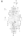
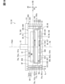
- FIG. 2 is a vertical cross-sectional view of the EPU in the first embodiment.
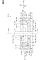
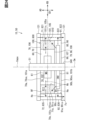
- FIG. 3 is a cross-sectional view of the inverter device.
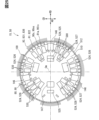
- FIG. 2 is a schematic cross-sectional view of the motor device.
- FIG. 3 is a diagram showing the configuration of an eVTOL.
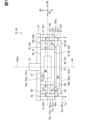
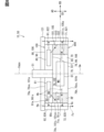
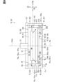
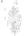
- FIG. 3 is a diagram showing the electrical configuration of the drive system.
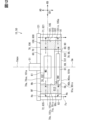
- FIG. 3 is a schematic vertical cross-sectional view of an EPU in a second embodiment.
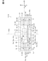
- FIG. 7 is a schematic vertical cross-sectional view of an EPU in a third embodiment.
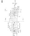
- FIG. 4 is a schematic vertical cross-sectional view of an EPU in a fourth embodiment.
- FIG. 7 is a schematic vertical cross-sectional view of an EPU in a fifth embodiment.
- FIG. 7 is a schematic vertical cross-sectional view of an EPU in a sixth embodiment.
- FIG. 7 is a schematic vertical cross-sectional view of an EPU in a seventh embodiment.
- FIG. 7 is a schematic vertical cross-sectional view of an EPU in an eighth embodiment.
- FIG. 7 is a schematic vertical cross-sectional view of an EPU in a ninth embodiment.
- FIG. 7 is a schematic cross-sectional view of an EPU in a tenth embodiment.
- FIG. 7 is a schematic vertical cross-sectional view of an EPU in an eleventh embodiment.
- FIG. 7 is a schematic vertical cross-sectional view of an EPU in a fifth embodiment.
- FIG. 7 is a schematic vertical cross-sectional view of an EPU in a sixth embodiment.
- FIG. 7
- FIG. 7 is a schematic vertical cross-sectional view of an EPU in a twelfth embodiment.
- FIG. 3 is a cross-sectional view of the inverter device.
- FIG. 7 is a schematic vertical cross-sectional view of an EPU in a thirteenth embodiment.
- FIG. 3 is a cross-sectional view of the inverter device.
- FIG. 7 is a schematic vertical cross-sectional view of an EPU in a fourteenth embodiment.
- FIG. 7 is a cross-sectional view of an inverter device in a fifteenth embodiment.
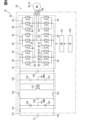
- the drive system 30 shown in FIG. 5 is installed in the eVTOL 10.
- the eVTOL 10 is an electric vertical takeoff and landing aircraft, and is capable of vertical takeoff and landing.
- eVTOL is an abbreviation for electric Vertical Take-Off and Landing aircraft.
- the eVTOL 10 is an aircraft that flies in the atmosphere and corresponds to a flying object.
- the eVTOL 10 is also an electric powered aircraft and is sometimes referred to as an electric flying vehicle.
- the eVTOL 10 is a manned aircraft on which a crew member rides.
- the drive system 30 is a system that drives the eVTOL 10 to fly.
- the eVTOL 10 has a fuselage 11 and a propeller 20.
- the fuselage 11 has a fuselage main body 12 and wings 13.
- the fuselage main body 12 is the fuselage of the fuselage 11, and has a shape that extends from front to back, for example.
- the fuselage main body 12 has a crew compartment for a crew member to ride.
- the wings 13 extend from the fuselage main body 12, and a plurality of wings 13 are provided in the fuselage main body 12.
- Wing 13 is a fixed wing.
- the plurality of wings 13 include a main wing, a tail wing, and the like.
- a plurality of propellers 20 are provided in the aircraft body 11.
- the eVTOL 10 is a multicopter having at least three propellers 20.
- at least four propellers 20 are provided in the aircraft body 11.
- the propeller 20 is provided on each of the fuselage main body 12 and the wings 13.
- the propeller 20 rotates around the propeller axis.
- the propeller axis is, for example, the centerline of the propeller 20.
- the propeller 20 can cause the eVTOL 10 to generate thrust and lift. Further, the propeller 20 is sometimes referred to as a rotor or a rotating blade.
- the propeller 20 has blades 21 and a boss 22.
- a plurality of blades 21 are arranged in the circumferential direction of the propeller axis.
- the boss 22 connects the plurality of blades 21.
- the blade 21 extends from the boss 22 in the radial direction of the propeller axis.
- the propeller 20 has a propeller shaft (not shown).
- the propeller shaft is a rotating shaft of the propeller 20 and extends from the boss 22 along the propeller axis.
- a propeller shaft is sometimes referred to as a propeller shaft.
- the eVTOL 10 is a tilt rotor machine.
- the propeller 20 can be tilted. That is, the tilt angle of the propeller 20 is adjustable.
- the orientation of the propeller 20 is set so that the propeller axis extends in the vertical direction.
- the propeller 20 functions as a lift rotor to generate lift on the eVTOL 10.
- the propeller 20 functions as a lift rotor, allowing the eVTOL 10 to hover and perform vertical takeoff and landing.
- the orientation of the propeller 20 is set so that the propeller axis extends in the front-rear direction. In this case, the propeller 20 functions as a cruise rotor for generating thrust in the eVTOL 10.
- the eVTOL 10 includes a battery 31, a distributor 32, a flight control device 40, and an EPU 50.
- a battery 31, a distributor 32, a flight control device 40, and an EPU 50 are included in the drive system 30.
- the battery 31 is electrically connected to the plurality of EPUs 50 .
- the battery 31 is a power supply section that supplies power to the EDS 50, and corresponds to a power supply section.
- the battery 31 is a DC voltage source that applies DC voltage to the EDS 50.
- the battery 31 has a secondary battery that can be charged and discharged. Battery 31 also supplies power to flight control device 40 . Note that, in addition to or in place of the battery 31, a fuel cell, a generator, or the like may be used as the power supply section.
- the distributor 32 is electrically connected to the battery 31 and the plurality of EPUs 50.
- Distributor 32 distributes power from battery 31 to a plurality of EPUs 50.
- the power distributed by the distributor 32 to the EPU 50 is driving power for driving the EPU 50.
- Flight control device 40 controls the drive system 30. Flight control device 40 performs flight control for causing eVTOL 10 to fly. Flight control device 40 is communicatively connected to a plurality of EPUs 50. Flight control device 40 individually controls a plurality of EPUs 50. Flight control device 40 controls EPU 50 via control circuit 160, which will be described later. Flight control device 40 controls control circuit 160.
- the EPU 50 is a device that drives the propeller 20 to drive and rotate it, and corresponds to a drive device.
- EPU is an abbreviation for Electric Propulsion Unit.
- the EPU 50 is sometimes referred to as an electric drive device or an electric drive system.
- the EPU 50 is provided individually for each of the plurality of propellers 20.
- the EPUs 50 are arranged on the propeller 20 along the propeller axis. All of the plurality of EPUs 50 are fixed to the aircraft body 11.
- the EPU 50 rotatably supports the propeller 20.
- EPU 50 is connected to propeller 20.
- the propeller 20 is fixed to the aircraft body 11 via the EPU 50. When the tilt angle of the propeller 20 is changed, the angle of the EPU 50 is also changed.
- the eVTOL 10 has a propulsion device 15.
- the propulsion device 15 is a device for propelling the eVTOL 10.
- the eVTOL 10 is propelled by the propulsion device 15 to be able to fly on a lift or the like.
- the propulsion device 15 has a propeller 20 and an EPU 50.
- the propeller 20 rotates as the EPU 50 is driven.
- the propeller 20 corresponds to a rotating body.
- the eVTOL 10 flies by rotation of the propeller 20. That is, the eVTOL 10 moves by the rotation of the propeller 20.
- the eVTOL 10 corresponds to a mobile object.
- the EPU 50 includes a motor device 60 and an inverter device 80.
- the EPU 50 includes one motor device 60 and one inverter device 80.
- the motor device 60 has a motor 61.
- Inverter device 80 has an inverter 81 .
- the motor 61 is electrically connected to the battery 31 via an inverter 81.
- the motor 61 is driven according to electric power supplied from the battery 31 via the inverter 81.
- the motor 61 is a multi-phase AC motor.
- the motor 61 is, for example, a three-phase AC motor, and has a U phase, a V phase, and a W phase.
- the motor 61 is a moving drive source for moving the moving body, and functions as an electric motor.
- As the motor 61 for example, a brushless motor is used.
- the motor 61 functions as a generator during regeneration.
- the motor 61 has multiple phase motor coils 211 (see FIG. 1).
- the motor coil 211 is a winding and forms an armature. Motor coils 211 are provided for each of the U phase, V phase, and W phase. Note that the motor 61 corresponds to a rotating electrical machine, and the EPU 50 corresponds to a rotating electrical machine unit.
- the inverter 81 drives the motor 61 by converting the electric power supplied to the motor 61.
- Inverter 81 converts the power supplied to motor 61 from direct current to alternating current.
- Inverter 81 is a power converter that converts power.
- the inverter 81 is a multi-phase power conversion unit, and performs power conversion for each of the multiple phases.
- the inverter 81 is, for example, a three-phase inverter, and performs power conversion for each of the U phase, V phase, and W phase.
- Inverter device 80 is sometimes referred to as a power converter device.
- the inverter device 80 has a P line 141 and an N line 142.
- P line 141 and N line 142 electrically connect battery 31 and inverter 81.
- P line 141 is electrically connected to the positive electrode of battery 31.
- N line 142 is electrically connected to the negative electrode of battery 31.
- the positive electrode is the electrode on the high potential side
- the negative electrode is the electrode on the low potential side.
- the P line 141 and the N line 142 are power lines for supplying power.
- the P line 141 is a power line on the high potential side, and is sometimes referred to as a high potential line.
- the N line 142 is a power line on the low potential side, and is sometimes referred to as a low potential line.
- the EPU 50 has an output line 143.
- Output line 143 is a power line for supplying power to motor 61.
- Output line 143 electrically connects motor 61 and inverter 81.
- the output line 143 is in a state where it is extended between the motor device 60 and the inverter device 80.
- the inverter device 80 includes a smoothing capacitor 145 and an EMI filter 150.
- Smoothing capacitor 145 is a capacitor that smoothes the DC voltage supplied from battery 31. Smoothing capacitor 145 is connected to P line 141 and N line 142 between battery 31 and inverter 81 . Smoothing capacitor 145 is connected in parallel to inverter 81 .
- the EMI filter 150 is a filter circuit that reduces electromagnetic noise.
- EMI filter 150 is connected to P line 141 and N line 142 between battery 31 and inverter 81 .
- EMI filter 150 is connected in parallel to smoothing capacitor 145 and inverter 81, for example.
- the EMI filter 150 includes a common mode coil 151, a normal mode coil 152, a Y capacitor 153, an X capacitor 154, and a varistor 155.
- the common mode coil 151 is a common mode choke coil and can reduce common mode noise.
- the normal mode coil 152 is a normal mode choke coil and is capable of reducing normal mode noise.
- Y capacitor 153 is a line bypass capacitor and can reduce common mode noise.
- the X capacitor 154 is an across-the-line capacitor and can reduce normal mode noise.
- the varistor 155 is capable of absorbing surge voltage and reduces the surge voltage. Note that the Y capacitor 153 and the varistor 155 are grounded to the ground GND.
- the inverter 81 is a power conversion circuit, for example, a DC-AC conversion circuit.
- the inverter 81 has upper and lower arm circuits 83 for multiple phases.
- the inverter 81 has upper and lower arm circuits 83 for each of the U phase, V phase, and W phase.
- the upper and lower arm circuits 83 are sometimes referred to as leg or arm circuits.
- the upper and lower arm circuit 83 has an upper arm 84 and a lower arm 85.
- the upper arm 84 and the lower arm 85 are connected in series to the battery 31.
- Upper arm 84 is connected to P line 141 and lower arm 85 is connected to N line 142.
- the output line 143 is connected to the upper and lower arm circuits 83 for each of the multiple phases. Output line 143 is connected between upper arm 84 and lower arm 85. The output line 143 connects the upper and lower arm circuits 83 and the coils in each of the plurality of phases. Output line 143 is connected to the opposite side of the coil from the neutral point.
- the upper arm 84 and the lower arm 85 have an arm switch 86 and a diode 87.
- the arm switch 86 is, for example, a transistor such as a MOSFET. MOSFET is an abbreviation for Metal-Oxide-Semiconductor Field-Effect Transistor.
- the arm switch 86 is a switching element, and can convert power by switching.
- the switch element may be a semiconductor element such as a power element.
- the arm switch 86 is a conversion switch for converting power.
- the drain of the arm switch 86 is connected to the P line 141.
- the source of the arm switch 86 is connected to the N line 142.
- the source of the arm switch 86 in the upper arm 84 and the drain of the arm switch 86 in the lower arm 85 are connected to each other.
- a diode 87 is connected in antiparallel to an arm switch 86 for circulation.
- the anode of the diode 87 is connected to the source of the corresponding arm switch 86, and the cathode is connected to the drain.
- the arm switch 86 can also be referred to as a semiconductor switch.
- Both the upper arm 84 and the lower arm 85 have a plurality of arm switches 86 and diodes 87.
- a plurality of arm switches 86 are connected in parallel, and a plurality of diodes 87 are connected in parallel.
- a plurality of sets including one arm switch 86 and one diode 87 are connected in parallel.
- six arm switches 86 and six diodes 87 are connected in parallel.
- the EPU 50 has a control circuit 160 and a drive circuit 161.
- Control circuit 160 and drive circuit 161 are included in inverter device 80.
- Control circuit 160 controls driving of inverter 81.
- Control circuit 160 controls driving of motor 61 via inverter 81.
- Control circuit 160 is sometimes referred to as a motor control section. In FIG. 6, the control circuit 160 is shown as CD, the drive circuit 161 as DD, and the motor 61 as MG.
- the control circuit 160 is a control device such as an ECU.
- ECU is an abbreviation for Electronic Control Unit.
- the control circuit 160 is mainly composed of a microcomputer including, for example, a processor, memory, I/O, and a bus connecting these.
- Memory is a non-transitory, tangible storage medium that non-temporarily stores computer-readable programs and data. Further, the non-transitory tangible storage medium is a non-transitory tangible storage medium, and is realized by a semiconductor memory, a magnetic disk, or the like.
- the control circuit 160 executes various processes related to driving the inverter 81 by executing a control program stored in the memory.
- Control circuit 160 is electrically connected to external devices, inverter 81, and various sensors.
- the external device is, for example, a higher-level ECU such as an integrated ECU mounted on a mobile object.
- Various sensors are provided in the EPU 50, for example.
- the control circuit 160 controls the inverter 81 by outputting a command signal to the inverter 81.
- the control circuit 160 generates command signals in response to control signals input from external devices, detection signals input from various sensors, and the like.
- Control circuit 160 controls inverter 81 via drive circuit 161.
- Control circuit 160 causes inverter 81 to perform power conversion.
- the drive circuit 161 is electrically connected to each of the plurality of arm switches 86 included in the inverter 81.
- Drive circuit 161 drives inverter 81 in response to a command signal from control circuit 160 .
- the drive circuit 161 drives the arm switch 86 by applying a drive voltage according to the command signal to the gate of the arm switch 86 .
- the drive circuit 161 can turn the arm switch 86 on and off.
- the drive circuit 161 is sometimes referred to as a driver.
- the inverter device 80 has a motor current sensor 146 and a battery current sensor 147.
- Motor current sensor 146 detects the current flowing through motor 61.
- a motor current sensor 146 is provided for the output line 143.
- Motor current sensor 146 detects the current flowing to motor 61 via output line 143.
- Motor current sensor 146 is provided, for example, for each of the U phase, V phase, and W phase.
- Motor current sensor 146 is electrically connected to control circuit 160 and outputs a detection signal to control circuit 160.
- the battery current sensor 147 detects the current flowing through the battery 31.
- a battery current sensor 147 is provided for the P line 141.
- Battery current sensor 147 detects the current flowing from battery 31 to inverter 81 via P line 141.
- Battery current sensor 147 is electrically connected to control circuit 160 and outputs a detection signal to control circuit 160.
- the EPU 50 has an EPU shaft 51.
- EPU shaft 51 connects motor 61 and propeller 20.
- the EPU shaft 51 rotates together with the propeller 20 as driven by the motor 61.
- the EPU shaft 51 rotates around the EPU axis Cepu.
- the EPU axis Cepu is the center line of the EPU shaft 51.
- the EPU axis Cepu coincides with the propeller axis.
- the propeller 20 and the EPU 50 are arranged along the EPU axis Cepu.
- propeller wind is generated as the propeller 20 rotates.
- the propeller wind is gas such as air flowing from the propeller 20 toward the EPU 50 along the EPU axis Cepu.
- Propeller wind corresponds to rotating wind.
- the EPU 50 is located on the leeward side of the propeller wind relative to the propeller 20.
- the motor device 60 and the inverter device 80 are arranged in the axial direction AD along the motor axis Cm.
- the motor device 60 is located on the windward side of the propeller wind with respect to the inverter device 80.
- the motor device 60 is provided between the propeller 20 and the inverter device 80 in the axial direction AD.
- the motor axis Cm is the center line of the motor 61, and is an imaginary line extending linearly.
- the motor axis Cm corresponds to the rotation axis.
- the axial direction AD is the direction in which the motor axis Cm extends.
- the axial direction AD, the radial direction RD, and the circumferential direction CD are orthogonal to each other.
- the circumferential direction CD is the rotation direction of the motor 61.
- the outer side is sometimes called the radially outer side or the outer peripheral side
- the inner side is sometimes called the radially inner side or the inner peripheral side.
- the motor axis Cm coincides with the EPU axis Cepu. Note that the motor axis Cm may be located at a position shifted from the EPU axis Cepu in the radial direction RD.
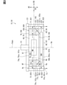
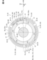
- FIG. 1 shows a longitudinal section of the EPU 50 taken along the motor axis Cm.
- the EPU 50 has a motor unit 100.
- the motor unit 100 includes a motor device 60 and an inverter device 80.
- the motor device 60 and the inverter device 80 are integrated into a unit.
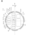
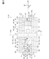
- FIG. 3 shows a cross section of the inverter device 80 taken perpendicular to the motor axis Cm.
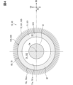
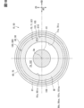
- FIG. 4 shows a cross section of the motor device 60 taken perpendicular to the motor axis Cm.
- the motor unit 100 has a unit housing 101.
- Unit housing 101 accommodates motor 61 and inverter 81.
- the unit housing 101 is formed into a cylindrical shape as a whole, and extends in the axial direction AD along the motor axis Cm.
- the motor 61 and the inverter 81 are housed in the unit housing 101, so that the motor device 60 and the inverter device 80 are integrated.
- the unit housing 101 corresponds to an accommodation housing.
- the unit housing 101 has a unit outer surface 101os and a unit inner surface 101is.
- the unit outer surface 101os is the outer surface of the unit housing 101.
- the unit inner surface 101is is the inner surface of the unit housing 101.
- the unit outer surface 101os and the unit inner surface 101is are formed by the flesh portion of the unit housing 101.
- the unit outer surface 101os corresponds to the outer surface of the accommodation housing.
- the motor unit 100 has a unit upstream wall surface 101a, a unit downstream wall surface 101b, and a unit outer peripheral wall surface 101c.
- the wall surfaces 101a to 101c are included in the unit outer surface 101os.
- the unit upstream wall surface 101a and the unit downstream wall surface 101b extend in a direction perpendicular to the motor axis Cm.
- the unit upstream wall surface 101a faces the upstream side of the propeller wind.
- the unit downstream wall surface 101b faces the downstream side of the propeller wind.
- the unit outer peripheral wall surface 101c extends in a direction perpendicular to the radial direction RD. Propeller wind tends to flow in the axial direction AD along the unit outer peripheral wall surface 101c.
- the unit housing 101 has a unit outer peripheral wall 105, an upstream plate 106, a downstream plate 107, and a partition plate 108.
- the unit outer peripheral wall 105 and the plates 106 to 108 are made of a metal material or the like and have thermal conductivity.
- the unit outer peripheral wall 105 forms a unit outer peripheral wall surface 101c.
- the unit outer peripheral wall 105 extends annularly in the circumferential direction CD.
- the upstream plate 106 forms a unit upstream wall surface 101a.
- the downstream plate 107 forms a unit downstream wall surface 101b.
- the upstream plate 106 and the downstream plate 107 extend in a plate shape in a direction perpendicular to the axial direction AD.
- the unit outer peripheral wall 105 is in a state where it spans an upstream plate 106 and a downstream plate 107.
- the unit housing 101 has a unit space 102.
- Unit space 102 is an internal space of unit housing 101.
- Partition plate 108 is provided inside unit housing 101.
- the partition plate 108 extends in a direction perpendicular to the axial direction AD.
- the partition plate 108 divides the unit space 102 in the axial direction AD.
- Partition plate 108 is provided between upstream plate 106 and downstream plate 107.
- the partition plate 108 is located away from both the upstream plate 106 and the downstream plate 107 in the axial direction AD.
- the plates 106 to 108 are members independent from the unit outer peripheral wall 105.
- the plates 106 to 108 are fixed to the unit outer peripheral wall 105 by bolts, welding, or the like. That is, the plates 106 to 108 are retrofitted to the unit outer peripheral wall 105.
- one of the plates 106 to 108 and the unit outer peripheral wall 105 may be integrally molded.
- the partition plate 108 and the unit outer peripheral wall 105 may be integrally formed.
- the unit housing 101 has a unit inner wall surface 105a.
- the unit inner wall surface 105a is included in the inner surface of the unit housing 101.
- the unit inner wall surface 105a is formed by the unit outer peripheral wall 105.
- the wall surface facing radially inward is the unit inner wall surface 105a
- the wall surface facing radially outside is the unit outer peripheral wall surface 101c.
- the motor device 60 includes a motor housing 70 in addition to the motor 61.
- Motor housing 70 accommodates motor 61.
- Motor housing 70 has a motor space 74 .
- Motor space 74 is an internal space of motor housing 70 .
- the motor space 74 is a space that accommodates the motor 61.
- the motor housing 70 has a motor outer peripheral wall 71.
- the motor outer peripheral wall 71 extends annularly in the circumferential direction CD.
- the motor space 74 is a space inside the motor outer peripheral wall 71.
- the motor 61 is housed inside the motor outer peripheral wall 71.
- the motor housing 70 has a motor upstream wall 78 and a motor downstream wall 79.
- the motor upstream wall 78 and the motor downstream wall 79 extend in a direction perpendicular to the axial direction AD.
- the motor upstream wall 78 and the motor downstream wall 79 are arranged in the axial direction AD with the motor outer circumferential wall 71 in between.
- the motor upstream wall 78 is provided on the windward side of the propeller wind with respect to the motor downstream wall 79.
- Motor upstream wall 78 is formed to include at least a portion of upstream plate 106.
- the motor downstream wall 79 is formed to include at least a portion of the partition plate 108.
- the motor housing 70 has a motor housing outer surface 70os and a motor housing inner surface 70is.
- Motor housing outer surface 70os is the outer surface of motor housing 70.
- Motor housing inner surface 70is is the inner surface of motor housing 70.
- the motor housing outer surface 70os and the motor housing inner surface 70is are formed by a motor outer peripheral wall 71, a motor upstream wall 78, and a motor downstream wall 79.
- the inverter device 80 includes an inverter housing 90 in addition to an inverter 81.
- Inverter housing 90 accommodates inverter 81.
- Inverter housing 90 has an inverter space 94 .
- Inverter space 94 is an internal space of inverter housing 90 .
- Inverter space 94 is a space that accommodates inverter 81.
- Inverter housing 90 has an inverter outer peripheral wall 91 .
- the inverter outer peripheral wall 91 extends annularly in the circumferential direction CD.
- the inverter space 94 is a space inside the inverter outer peripheral wall 91.
- the inverter 81 is housed inside the inverter outer peripheral wall 91.
- the inverter housing 90 has an inverter upstream wall 98 and an inverter downstream wall 99.
- the inverter upstream wall 98 and the inverter downstream wall 99 extend in a direction perpendicular to the axial direction AD.
- the inverter upstream wall 98 and the inverter downstream wall 99 are arranged in the axial direction AD with the inverter outer peripheral wall 91 in between.
- the inverter upstream wall 98 is provided on the windward side of the propeller wind with respect to the inverter downstream wall 99.
- the inverter upstream wall 98 is formed to include at least a portion of the partition plate 108.
- Inverter downstream wall 99 is formed to include at least a portion of downstream plate 107.
- the inverter housing 90 has an inverter housing outer surface 90os and an inverter housing inner surface 90is.
- Inverter housing outer surface 90os is the outer surface of inverter housing 90.
- Inverter housing inner surface 90is is the inner surface of inverter housing 90.
- the inverter housing outer surface 90os and the inverter housing inner surface 90is are formed by an inverter outer peripheral wall 91, an inverter upstream wall 98, and an inverter downstream wall 99.
- the motor housing 70 and the inverter housing 90 are integrated.
- Motor housing 70 and inverter housing 90 are included in unit housing 101.
- the motor outer peripheral wall 71 and the inverter outer peripheral wall 91 are included in the unit outer peripheral wall 105.
- the unit outer surface 101os includes a motor housing outer surface 70os and an inverter housing outer surface 90os.
- the unit inner surface 101is includes a motor housing inner surface 70is and an inverter housing inner surface 90is.
- the motor housing 70 and the inverter housing 90 are arranged in the axial direction AD.
- the inverter housing 90 is located on the leeward side of the propeller wind with respect to the motor housing 70.
- the part on the windward side is the motor housing 70
- the part on the leeward side is the inverter housing 90.
- the part that forms the motor space 74 is the motor housing 70.
- the motor outer peripheral wall 71, the upstream plate 106, and the partition plate 108 form the motor housing 70.
- the motor housing 70 has a motor upstream wall surface 70a, a motor outer peripheral wall surface 70c, and a motor inner wall surface 71a.
- the motor upstream wall surface 70a and the motor outer peripheral wall surface 70c are included in the motor housing outer surface 70os.
- the motor inner wall surface 71a is included in the motor housing inner surface 70is.
- Motor inner wall surface 71 a is an inner wall surface of motor housing 70 .
- the motor upstream wall surface 70a is included in the unit upstream wall surface 101a.
- the motor outer peripheral wall surface 70c is included in the unit outer peripheral wall surface 101c.
- the motor inner wall surface 71a is included in the unit inner wall surface 105a.
- the motor outer peripheral wall surface 70c and the motor inner wall surface 71a are formed by the motor outer peripheral wall 71.
- the part that forms the inverter space 94 is the inverter housing 90.
- the inverter outer peripheral wall 91, the downstream plate 107, and the partition plate 108 form the inverter housing 90.
- the inverter housing 90 has an inverter downstream wall surface 90b, an inverter outer peripheral wall surface 90c, and an inverter inner wall surface 91a.
- the inverter downstream wall surface 90b and the inverter outer peripheral wall surface 90c are included in the inverter housing outer surface 90os.
- the inverter inner wall surface 91a is included in the inverter housing inner surface 90is.
- Inverter inner wall surface 91 a is an inner wall surface of inverter housing 90 .
- the inverter downstream wall surface 90b is included in the unit downstream wall surface 101b.
- the inverter outer peripheral wall surface 90c is included in the unit outer peripheral wall surface 101c.
- the inverter inner wall surface 91a is included in the unit inner wall surface 105a.
- the inverter outer peripheral wall surface 90c and the inverter inner wall surface 91a are formed by the inverter outer peripheral wall 91.
- the inverter inner wall surface 91a corresponds to an inner wall surface.
- the motor space 74 and the inverter space 94 are arranged in the axial direction AD.
- Partition plate 108 is between motor space 74 and inverter space 94.
- the motor space 74 and the inverter space 94 are separated by a partition plate 108.
- Motor space 74 is a space between upstream plate 106 and partition plate 108.
- Inverter space 94 is a space between downstream plate 107 and partition plate 108.
- the motor 61 includes a stator 200, a first rotor 300a, a second rotor 300b, and a motor shaft 340.
- Stator 200 is a stator.
- the stator 200 has a motor coil 211 and a coil protector 250.
- the motor coil 211 extends in the circumferential direction CD along the motor inner wall surface 71a.
- the motor coil 211 is formed into an annular shape as a whole.
- the motor coil 211 corresponds to a coil.
- the coil protector 250 protects the motor coil 211.
- the coil protector 250 is made of a resin material or the like.
- the coil protector 250 is fixed to the motor housing 70 while covering the motor coil 211.
- the coil protection portion 250 is in close contact with the motor inner wall surface 71a.
- the coil protector 250 has thermal conductivity. The coil protector 250 easily transfers the heat of the motor coil 211 to the motor housing 70.
- the rotors 300a and 300b are rotors. Rotors 300a and 300b rotate relative to stator 200. The rotors 300a and 300b rotate around the motor axis Cm. The motor axis Cm is the center line of the rotors 300a, 300b. The stator 200 and the motor coil extend annularly in the circumferential direction CD. The centerline of stator 200 coincides with motor axis Cm.
- the motor device 60 is an axial gap type rotating electric machine.
- the motor 61 is an axial gap type motor.
- a stator 200 and rotors 300a, 300b are arranged in the axial direction AD along the motor axis Cm.
- the motor device 60 is a double rotor type rotating electric machine.
- the motor 61 is a double rotor type motor.
- the first rotor 300a and the second rotor 300b are arranged in the axial direction AD.
- the stator 200 is provided between two rotors, a first rotor 300a and a second rotor 300b.
- Stator 200 is located away from rotors 300a and 300b in the axial direction AD.
- the motor 61 of this embodiment is sometimes referred to as a double axial motor.
- the first rotor 300a is provided on the upstream plate 106 side.
- the first rotor 300a is located away from the upstream plate 106 toward the partition plate 108.
- the first rotor 300a extends in the circumferential direction CD along the upstream plate 106.
- the second rotor 300b is provided on the partition plate 108 side.
- the second rotor 300b is located away from the partition plate 108 toward the upstream plate 106.
- the second rotor 300b extends in the circumferential direction CD along the partition plate 108.
- the rotors 300a and 300b are located away from the motor outer peripheral wall 71 in the radial direction.
- the motor shaft 340 supports the rotors 300a and 300b. Motor shaft 340 rotates about motor axis Cm together with rotors 300a and 300b. The center line of the motor shaft 340 coincides with the motor axis Cm. The motor shaft 340 connects the rotors 300a, 300b and the EPU shaft 51. The motor shaft 340 and the EPU shaft 51 are arranged in the axial direction AD. The centerline of the motor shaft 340 coincides with the EPU axis Cepu. Note that the center line of the motor shaft 340 may be located at a position shifted from the EPU axis Cepu in the radial direction RD.
- the motor shaft 340 has a shaft body 341 and a shaft flange 342.
- the shaft body 341 is formed in a cylindrical shape and extends in the axial direction AD along the motor axis Cm.
- the shaft flange 342 extends radially outward from the shaft body 341.
- the shaft flange 342 is fixed to the rotors 300a, 300b.
- the shaft flange 342 divides the motor space 74 in the axial direction AD.
- the rotors 300a and 300b are located away from the shaft body 341 in the radial direction.
- the rotors 300a and 300b have magnets 310 and magnet holders 320.
- a plurality of magnets 310 are arranged in the circumferential direction CD in each of the rotors 300a and 300b.
- Magnet 310 is a permanent magnet and forms the disclosure.
- the magnets 310 of the first rotor 300a and the magnets 310 of the second rotor 300b are arranged in the axial direction AD with the stator 200 in between.
- the rotors 300a and 300b are provided with magnets 310 aligned with the motor coil 211 in the axial direction AD.
- Magnet holder 320 supports magnet 310.
- the magnet holder 320 forms the outer shell of the rotors 300a, 300b as a whole.
- Magnet holder 320 is fixed to shaft flange 342.
- the motor device 60 has an upstream bearing 360 and a downstream bearing 361. Bearings 360, 361 rotatably support motor shaft 340.
- the upstream bearing 360 and the downstream bearing 361 are arranged in the axial direction AD via the shaft flange 342.
- Upstream bearing 360 is fixed to upstream plate 106.
- the downstream bearing 361 is fixed to the downstream plate 107.
- the motor device 60 at least a portion of the motor 61 is housed in a motor space 74.
- the motor space 74 accommodates rotors 300a, 300b, stator 200, and bearings 360, 361. Furthermore, at least a portion of the motor shaft 340 is accommodated in the motor space 74 .
- the inverter device 80 includes a drive board 510, a filter component 524, an arm switch section 530, a control board 550, and a smoothing capacitor section 580.
- the drive board 510, filter component 524, arm switch section 530, control board 550, and smoothing capacitor 145 are housed in the inverter housing 90.
- the drive board 510, the arm switch section 530, and the like form an inverter 81.
- a microcomputer 165 is mounted on the control board 550.
- the control board 550, the microcomputer 165, and the like form a control circuit 160.
- the drive board 510 and the control board 550 are formed into plate shapes and extend in a direction perpendicular to the axial direction AD.
- the drive board 510 and the control board 550 are circuit boards having wiring patterns and the like.
- the drive board 510 and the control board 550 are arranged in the axial direction AD.
- Control board 550 is between drive board 510 and downstream plate 107. In the axial direction AD, the distance between the drive board 510 and the control board 550 is smaller than the distance between the drive board 510 and the partition plate 108.
- the drive board 510 partitions the inverter space 94 into a first drive space 94a and a second drive space 94b.
- the first drive space 94a and the second drive space 94b are included in the inverter space 94.
- the first drive space 94a and the second drive space 94b are lined up in the axial direction AD with the drive board 510 in between.
- the first drive space 94a is a space between the drive board 510 and the partition plate 108.
- the second drive space 94b is a space between the drive board 510 and the downstream plate 107.
- the control board 550 is provided in the second drive space 94b.
- the control board 550 has a board opening 553.
- the substrate opening 553 penetrates the control substrate 550 in the axial direction AD.
- a substrate opening 553 is provided at the center of the control substrate 550.
- the center of the substrate opening 553 is located at a position where the motor axis Cm passes.
- the inner diameter of the substrate opening 553 is larger than the outer diameter of the shaft body 341, for example.
- the drive outer peripheral end 512 extends in the circumferential direction CD along the inverter inner wall surface 91a.
- the drive outer peripheral end 512 is the outer peripheral end of the drive board 510.
- the drive outer peripheral end 512 is in a position in contact with or close to the inverter inner wall surface 91a.
- a control outer peripheral end 552 extends in the circumferential direction CD along the inverter inner wall surface 91a.
- the control outer peripheral end 552 is the outer peripheral end of the control board 550.
- the control outer peripheral end 552 is in contact with or close to the inverter inner wall surface 91a.
- the drive board 510 has a first drive surface 510a and a second drive surface 510b. Of the pair of plate surfaces of the drive board 510, the plate surface on the partition plate 108 side is the first drive surface 510a, and the plate surface on the downstream plate 107 side is the second drive surface 510b.
- the second drive surface 510b extends along the control board 550.
- the drive board 510 is a circuit board to which power for driving the motor 61 is supplied.
- Drive board 510 is sometimes referred to as a power board.
- a plurality of filter components 524 and a plurality of smoothing capacitor sections 580 are provided on the drive board 510.
- the filter component 524 and the smoothing capacitor section 580 are mounted on the drive board 510 in a state that they protrude from the first drive surface 510a.
- the smoothing capacitor section 580 is a component that includes the smoothing capacitor 145.
- the smoothing capacitor section 580 includes an element that forms the smoothing capacitor 145 and a protective part such as resin that protects this element.
- the plurality of filter components 524 include a common mode coil section 525, a normal mode coil section 526, a Y capacitor section 527, and an X capacitor section 528.
- the common mode coil section 525 includes a common mode coil 151.
- the common mode coil section 525 includes an element that forms the common mode coil 151 and a protective section such as resin that protects this element.
- a plurality of common mode coil sections 525 are provided on the drive board 510.
- the normal mode coil section 526 includes a normal mode coil 152.
- the normal mode coil section 526 includes an element that forms the normal mode coil 152 and a protective section made of resin or the like that protects this element.
- a plurality of normal mode coil sections 526 are provided on the drive board 510.
- the Y capacitor section 527 has a Y capacitor 153.
- the Y capacitor portion 527 includes an element forming the Y capacitor 153 and a protective portion such as resin that protects this element.
- a plurality of Y capacitor sections 527 are provided on the drive board 510.
- the X capacitor section 528 has an X capacitor 154.
- the X capacitor section 528 includes an element that forms the X capacitor 154 and a protective section such as resin that protects this element.
- a plurality of X capacitor sections 528 are provided on the drive board 510.
- the current sensors 146 and 147 are provided on the drive board 510 together with the smoothing capacitor section 580 and the like.
- the current sensors 146 and 147 are mounted on the drive board 510 in a state that they protrude from the first drive surface 510a.
- a plurality of motor current sensors 146 are provided according to the U phase, V phase, and W phase.
- One battery current sensor 147 is provided for each P line 141 .
- the inverter device 80 includes an arm switch section 530.
- the arm switch section 530 has an arm switch 86.
- the arm switch section 530 includes an element such as a MOSFET that forms the arm switch 86, and a protective section such as a resin that protects this element.
- a plurality of arm switch sections 530 are arranged in the circumferential direction CD along the inverter inner wall surface 91a.
- the arm switch section 530 is provided on the first drive surface 510a side with respect to the drive board 510. For example, the arm switch section 530 is located away from the drive board 510 toward the partition plate 108.
- the arm switch section 530 has a switch body and a switch terminal.
- the switch body includes elements such as MOSFETs and a protection section.
- the switch body is formed, for example, in the shape of a rectangular parallelepiped.
- the switch terminal is a terminal such as a drain terminal extending from the switch body.
- a plurality of arm switch sections 530 are provided on the drive board 510.
- the arm switch section 530 is mounted on the drive board 510 in a state protruding from the first drive surface 510a.
- the inverter space 94 accommodates a filter component 524, an arm switch section 530, and a smoothing capacitor section 580. Further, the inverter space 94 accommodates a drive board 510, a control board 550, and a microcomputer 165.
- the inverter space 94 accommodates heat-generating components that generate heat when energized. Examples of the heat generating components include the arm switch section 530, the smoothing capacitor section 580, and the filter component 524.
- the arm switch section 530, the filter component 524, and the smoothing capacitor section 580 are arranged in the radial direction RD.
- a plurality of smoothing capacitor sections 580 are provided between a plurality of filter components 524 and a plurality of arm switch sections 530.
- a plurality of smoothing capacitor sections 580 are arranged in a direction perpendicular to the direction in which filter component 524 and arm switch section 530 are arranged.
- the plurality of arm switch sections 530 are arranged in the radial direction RD.
- the plurality of filter parts 524 are also arranged in the radial direction RD.
- the inverter device 80 has a power connector 96 and a signal connector 97.
- the power connector 96 and the signal connector 97 are connector parts for connecting the inverter device 80 to external equipment.
- External devices to which the power connector 96 is connected include the battery 31 and the like.
- the power connector 96 is electrically connected to the battery 31 via a power cable or the like.
- External devices to which the signal connector 97 is connected include the flight control device 40 and the like.
- the signal connector 97 is communicably connected to the flight control device 40 via a signal cable or the like.
- a power connector 96 and a signal connector 97 are provided on the outer surface of the inverter housing 90.
- the power connector 96 is provided on the inverter outer peripheral wall surface 90c.
- the signal connector 97 is provided on the inverter downstream wall surface 90b.
- the output of the motor 61 is used as the output of the EPU 50.
- the output of the motor 61 is current, voltage, workload, energy, torque, motor rotation speed, and the like. There is a concern that the output of the motor 61 will decrease if the motor temperature becomes too high.
- the motor temperature is the temperature of the motor device 60 and the motor 61, and is the temperature of the motor coil 211, the coil protector 250, the motor space 74, and the like.
- current, voltage, etc. are output from the inverter 81.
- the inverter temperature is the temperature of the inverter device 80 and the inverter 81, and is the temperature of the arm switch section 530, the inverter space 94, and the like.
- the motor device 60 and the inverter device 80 are cooled, so that the output of the motor device 60 and the inverter device 80 is less likely to decrease. That is, the output density [kw/kg] of the EPU 50 is less likely to decrease.
- the power density is the power per unit mass of the EPU 50. In the EPU 50, the output density tends to increase by cooling the motor device 60 and the inverter device 80.
- the EPU 50 uses an air cooling system and a liquid cooling system as cooling systems for cooling the EPU 50.
- the EPU 50 uses an external cooling system that cools the EPU 50 from the outside as an air cooling system.
- the EPU 50 is cooled by the outside air Fo flowing outside the EPU 50.
- the outside air Fo is a gas such as outside air that exists outside the EPU 50.
- the motor 61 and the inverter 81 are cooled by discharging the heat from the motor 61 and the inverter 81 to the outside air Fo.
- the outside air Fo flows along the unit outer surface 101os.
- the outside air Fo flows in the axial direction AD along the unit outer peripheral wall surface 101c.
- the EPU 50 has outer peripheral wall fins 831.
- the outer peripheral wall fin 831 is included in the motor unit 100.
- the outer peripheral wall fin 831 is provided on the unit outer peripheral wall surface 101c.
- the outer peripheral wall fins 831 are heat radiation fins that radiate heat from the motor unit 100 to the outside.
- the outer peripheral wall fins 831 cool the motor unit 100 by heat radiation.
- the outer peripheral wall fin 831 is made of a metal material or the like and has thermal conductivity.
- the outer circumferential wall fins 831 protrude radially outward from the unit outer circumferential wall 105.
- the outer peripheral wall fin 831 is formed into a plate shape and extends in a direction perpendicular to the circumferential direction CD.
- the outer peripheral wall fin 831 extends in the axial direction AD.
- a plurality of outer peripheral wall fins 831 are arranged in the circumferential direction CD.
- the EPU 50 has a motor fin 72 and an inverter fin 92.
- the motor fins 72 and the inverter fins 92 are included in the outer peripheral wall fins 831.
- the portion provided on the motor outer circumferential wall surface 70c is the motor fin 72.
- Motor fins 72 are included in motor housing 70 .
- the portion provided on the inverter outer circumferential wall surface 90c is the inverter fin 92.
- Inverter fins 92 are included in inverter housing 90.
- the motor fin 72 and the inverter fin 92 may be provided integrally or may be provided apart from each other.
- the cooling effect of the motor unit 100 by the outside air Fo is enhanced by the outer peripheral wall fins 831. Since the outer peripheral wall fins 831 extend in the axial direction AD, the outside air Fo can easily flow along the outer peripheral wall fins 831. Therefore, the heat of the motor unit 100 is easily released from the outer peripheral wall fins 831 to the outside air Fo. For example, the heat of the motor device 60 is likely to be released from the motor fins 72 to the outside air Fo, and the heat of the inverter device 80 is likely to be released from the inverter fins 92 to the outside air Fo.
- the EPU 50 has a blower fan 121.
- the blower fans 121 are arranged in the motor unit 100 in the axial direction AD.
- the blower fan 121 is provided between the propeller 20 and the motor unit 100 in the axial direction AD.
- the blower fan 121 is located on the windward side of the propeller wind relative to the motor unit 100.
- the blower fan 121 blows outside air Fo to flow along the outer peripheral wall fins 831.
- the blower fan 121 blows outside air Fo toward the leeward side of the propeller wind.
- the blowing fan 121 forces the outside air Fo toward the motor unit 100.
- the ventilation fan 121 is sometimes referred to as a pressure fan.
- the blower fan 121 blows air as the motor 61 is driven.
- the blower fan 121 is provided on the EPU shaft 51.
- the blower fan 121 is connected to the motor shaft 340 via the EPU shaft 51.
- the blower fan 121 rotates together with the motor shaft 340 about the motor axis Cm.
- the blower fan 121 is an axial fan and blows air in the axial direction AD.
- the blower fan 121 is a mechanical fan rotated by a motor shaft 340.
- the blower fan 121 has a blower blade 122 and a blower boss 123.
- a plurality of blower blades 122 are arranged in the circumferential direction CD.
- the ventilation boss 123 connects the plurality of ventilation blades 122.
- the blower blade 122 extends radially outward from the blower boss 123.
- the blow boss 123 is fixed to the EPU shaft 51.
- the blow boss 123 extends in the circumferential direction CD along the outer peripheral surface of the EPU shaft 51. At least a portion of the blower blade 122 is located in line with the outer peripheral wall fin 831 in the axial direction AD.
- the EPU 50 has a cooling device 800.
- Cooling device 800 is included in a liquid cooling system. Cooling device 800 cools EPU 50 using refrigerant RF.
- refrigerant RF for example, a liquid such as a cooling liquid is used.
- Refrigerant RF is sometimes referred to as a liquid refrigerant.
- a cooling method using refrigerant RF is used as a cooling method.
- the motor 61 and the inverter 81 are cooled by releasing heat from the motor 61 and the inverter 81 to the refrigerant RF.
- the heat of the refrigerant RF is released to the outside air Fo, for example, via the outer peripheral wall fins 831.
- the cooling device 800 has a refrigerant pump 801 and a refrigerant passage 810.
- Refrigerant passage 810 is a passage through which refrigerant RF flows.
- Refrigerant passage 810 is a circulation passage that circulates refrigerant RF in cooling device 800.
- the refrigerant passage 810 is filled with refrigerant RF.
- the refrigerant passage 810 is included in the EPU 50 and circulates refrigerant RF in the EPU 50.
- Refrigerant passage 810 is provided so that refrigerant RF cools both motor device 60 and inverter device 80 .
- the EPU 50 has a passage forming portion in which a refrigerant passage 810 is formed.
- the passage forming portion is included in the unit housing 101 and the like.
- the passage forming part is included in the liquid cooling system together with the cooling device 800.
- the refrigerant pump 801 pumps the refrigerant RF in the refrigerant passage 810 so that the refrigerant RF flows through the refrigerant passage 810.
- Refrigerant pump 801 is a circulation pump that circulates refrigerant RF in refrigerant passage 810.
- Refrigerant pump 801 is, for example, an electric pump.
- Refrigerant pump 801 is driven by power from battery 31 .
- Refrigerant pump 801 is included in inverter device 80.
- Refrigerant pump 801 is provided, for example, on drive board 510.
- the refrigerant passage 810 has a motor outer peripheral path 811.
- the motor outer circumferential path 811 is provided so as to cover the motor 61 from the outer circumferential side.
- the motor outer circumferential path 811 is a water jacket for the motor 61.
- the motor outer circumferential path 811 is formed in an annular shape so as to extend in the circumferential direction CD.
- the motor outer peripheral path 811 is provided in the motor housing 70. On the other hand, the motor outer circumferential path 811 is not provided in the inverter housing 90.
- the motor outer circumferential path 811 is provided at a position that covers the motor coil 211 from the outer circumferential side.
- the motor outer circumferential path 811 extends along the outer circumferential surface of the motor coil 211.
- the motor outer circumferential path 811 is capable of cooling at least the motor coil 211 of the motor 61 .
- the motor outer circumferential path 811 cools the motor coil 211 from the outer circumferential side.
- the motor outer circumferential path 811 corresponds to a coil cooling path.
- the motor outer peripheral path 811 extends along the unit outer surface 101os so that the refrigerant RF flows along the unit outer surface 101os.
- the motor outer circumferential path 811 corresponds to an outer surface passage.
- the motor outer circumferential path 811 is built into the unit housing 101.
- the motor outer peripheral path 811 is provided inside the unit outer surface 101os in the unit housing 101.
- the motor outer circumferential path 811 corresponds to a built-in passage.
- the motor outer circumferential path 811 is provided in the unit housing 101 between the unit outer surface 101os and the unit inner surface 101is.
- the motor unit 100 has a unit liquid cooling section 821 and liquid cooling fins 835.
- the unit liquid cooling section 821 is a part of the unit housing 101 that performs liquid cooling using refrigerant RF.
- the unit liquid cooling section 821 is a passage forming section in which the motor outer peripheral path 811 is formed in the unit housing 101 .
- the unit liquid cooling section 821 forms a unit outer surface 101os and a unit inner surface 101is.
- the unit liquid cooling section 821 has a motor outer circumferential path 811 built therein.
- the unit liquid cooling section 821 corresponds to a built-in passage section.
- the liquid cooling fins 835 are heat radiation fins that radiate heat from the unit liquid cooling section 821 to the outside.
- the liquid cooling fins 835 are provided outside the unit liquid cooling section 821.
- the liquid cooling fins 835 are provided on the unit outer surface 101os in the unit liquid cooling section 821.
- a plurality of liquid cooling fins 835 are arranged along the unit outer surface 101os.
- the liquid cooling fins 835 extend outward from the unit liquid cooling section 821.
- the liquid cooling fins 835 release heat of the refrigerant RF flowing inside the unit liquid cooling section 821 to the outside.
- the liquid cooling fins 835 correspond to refrigerant fins and outer fins.
- the motor outer circumferential path 811 is included in the motor device 60.
- the motor outer circumferential path 811 extends along the motor housing outer surface 70os so that the refrigerant RF flows along the motor housing outer surface 70os.
- the motor outer circumferential path 811 is built into the motor housing 70 .
- the motor outer circumferential path 811 is provided in the motor housing 70 between the motor housing outer surface 70os and the motor housing inner surface 70is.
- Unit liquid cooling section 821 is included in motor housing 70 .
- the motor outer circumferential path 811 extends along the motor outer circumferential wall surface 70c so that the refrigerant RF flows along the motor outer circumferential wall surface 70c.
- the motor outer circumferential path 811 is built into the motor outer circumferential wall 71.
- the motor outer peripheral path 811 extends in the axial direction AD so as to span the motor upstream wall 78 and the motor downstream wall 79.
- the motor outer circumferential path 811 is provided on the motor outer circumferential wall 71 between the motor outer circumferential wall surface 70c and the motor inner wall surface 71a.
- the unit liquid cooling section 821 has at least a portion of the motor outer peripheral wall 71.
- the motor outer peripheral wall 71 is the unit liquid cooling section 821.
- the liquid cooling fins 835 are at least a portion of the outer peripheral wall fins 831. In this embodiment, the liquid cooling fins 835 are at least part of the motor fins 72.
- motor fins 72 are liquid cooling fins 835.
- the motor fins 72 act as liquid cooling fins 835 to release heat of the refrigerant RF flowing inside the motor outer peripheral wall 71 to the outside.
- the motor outer circumferential path 811 is provided at a position aligned with both the motor device 60 and the inverter device 80 in a direction perpendicular to the circumferential direction CD.
- the motor outer circumferential path 811 corresponds to a common path.
- the motor outer circumferential path 811 and the motor device 60 are lined up.
- the motor outer circumferential path 811 is located on the radially outer side of the motor housing 70, so that the motor outer circumferential path 811 and the motor device 60 are lined up in the radial direction RD.
- the motor outer circumferential path 811 is provided on the outer circumferential side of the motor device 60.
- the motor outer peripheral path 811 is lined up in the radial direction RD on the motor housing inner surface 70is.
- the refrigerant RF flowing through the motor outer circumferential path 811 cools the motor device 60 from the outside in the radial direction.
- the refrigerant RF flowing through the motor outer circumferential path 811 cools the motor coil 211 from the outer circumferential side.
- the motor outer circumferential path 811 and the inverter device 80 are lined up.
- the motor outer peripheral path 811 is provided between the inverter housing inner surface 90is and the motor upstream wall surface 70a in the axial direction AD. Since the motor outer peripheral wall 71 has the unit liquid cooling portion 821, the motor inner wall surface 71a is provided radially inward than the inverter inner wall surface 91a in the radial direction RD. At least a portion of the motor outer circumferential path 811 is located radially inner than the inverter inner wall surface 91a. The refrigerant RF flowing through the motor outer circumferential path 811 cools the inverter device 80 from the inverter upstream wall surface 90a side.
- the motor unit 100 has a unit air cooling section 822 and air cooling fins 836.
- the unit air cooling section 822 is a part of the unit housing 101 that performs air cooling.
- the unit air cooling section 822 is arranged in line with the unit liquid cooling section 821 along the unit outer surface 101os.
- the unit air cooling section 822 and the unit liquid cooling section 821 are arranged in the axial direction AD along the unit outer surface 101os.
- the unit air cooling section 822 is provided on the leeward side of the outside air Fo with respect to the unit liquid cooling section 821.
- the unit air cooling section 822 does not form the refrigerant passage 810.
- the air cooling fins 836 are radiation fins that radiate heat from the unit air cooling section 822 to the outside.
- the air cooling fins 836 are provided outside the unit air cooling section 822.
- the air cooling fins 836 are provided on the unit outer surface 101os in the unit air cooling section 822.
- a plurality of air cooling fins 836 are arranged along the unit outer surface 101os.
- the air cooling fins 836 extend outward from the unit air cooling section 822.
- the air cooling fins 836 are aligned with the liquid cooling fins 835 along the unit outer surface 101os.
- the air cooling fins 836 and the liquid cooling fins 835 are arranged in the axial direction AD along the unit outer surface 101os.
- the air cooling fins 836 are provided on the leeward side of the outside air Fo with respect to the liquid cooling fins 835.
- the air cooling fins 836 radiate heat from the unit housing 101 to the outside.
- Air cooling fins 836 correspond to housing fins. Note that the liquid cooling fins 835 and the air cooling fins 836 may be provided integrally or may be provided apart from each other.
- the unit air cooling section 822 is included in the inverter housing 90.
- the unit air cooling section 822 is at least a portion of the inverter outer peripheral wall 91.
- the inverter outer peripheral wall 91 is the unit air cooling section 822.
- the unit air cooling section 822 is arranged in the unit liquid cooling section 821 in the axial direction AD.
- the air cooling fins 836 are at least a portion of the outer peripheral wall fins 831.
- the air cooling fins 836 are at least part of the inverter fins 92.
- inverter fins 92 are air cooling fins 836.
- the inverter fins 92 serve as air cooling fins 836 to radiate heat from the inverter outer peripheral wall 91 to the outside.
- the heat transmitted to the unit air cooling section 822 in the inverter device 80 is released to the outside from the air cooling fins 836 as heat Ha.
- heat generated in the arm switch section 530 and the like is transmitted from the inverter space 94 to the inverter outer peripheral wall 91 as heat Ha, and then is released from the inverter fins 92 to the outside.
- the heat transmitted to the unit liquid cooling section 821 in the motor unit 100 is applied to the refrigerant RF as heat Hb.
- heat generated in the motor coil 211 and the like is transmitted from the motor space 74 to the refrigerant RF as heat Hb.
- heat generated in the arm switch section 530 and the like is transmitted from the inverter space 94 to the refrigerant RF as heat Hb.
- the heat Hb transferred to the refrigerant RF is released to the outside from the liquid cooling fins 835 in the unit liquid cooling section 821 as heat Hc.
- the heat Hc is transmitted from the refrigerant RF to the motor fins 72 on the motor outer peripheral wall 71, and is released from the motor fins 72 to the outside.
- heat is also released to the outside from parts different from the unit liquid cooling section 821 and the unit air cooling section 822.
- the heat of the motor device 60 and the inverter device 80 is also released to the outside from the upstream plate 106 and the downstream plate 107.
- the refrigerant RF circulates through the refrigerant passage 810 so as to pass through the motor outer peripheral path 811.
- the refrigerant RF circulates in the circumferential direction CD.
- the refrigerant RF absorbs the heat of the motor device 60 and the inverter device 80 in the motor outer peripheral path 811, and releases the heat to the outside from the liquid cooling fins 835. Further, the heat of the refrigerant RF is released to the outside not only from the liquid cooling fins 835 but also from the unit outer surface 101os and the air cooling fins 836.
- the outside air Fo flows along the outer peripheral wall fins 831.
- the outside air Fo flows along the liquid cooling fins 835 and then along the air cooling fins 836. That is, the outside air Fo flows along the motor fins 72 and then the inverter fins 92.
- the release of heat Hc from the inverter fins 92 to the outside air Fo is promoted by the outside air.
- the release of heat Ha from the motor fins 72 to the outside air Fo is promoted by the outside air.
- both the motor device 60 and the inverter device 80 are cooled by the refrigerant RF circulating in the refrigerant passage 810.
- both an increase in the temperature of the motor device 60 and an increase in the temperature of the inverter device 80 can be suppressed by the refrigerant RF. Therefore, in each of the motor device 60 and the inverter device 80, it is less likely that the output of current or the like will decrease due to a rise in temperature. Therefore, the output density of the EPU 50 can be improved.
- the refrigerant RF circulates through the refrigerant passage 810, there is no need to supply the refrigerant RF to the EPU 50 from the outside. Therefore, there is no need to mount a supply device for supplying refrigerant RF to the EPU 50 in the eVTOL 10. Therefore, the weight of the eVTOL 10 can be reduced by eliminating the need for a supply device. Further, there is no need to connect a supply pipe to the EPU 50 for supplying the refrigerant RF from the supply device to the EPU 50. Therefore, the weight of the EPU 50 can be reduced by eliminating the need for supply piping.
- a comparative example is assumed in which only one of the motor device 60 and the inverter device 80 is cooled by a liquid cooling system.
- the cooling performance required of the liquid cooling system is limited to a cooling performance that can cool only one of the motor device 60 and the inverter device 80.
- the required cooling performance is not high, so that the output is likely to decrease as the temperature of the EPU 50 increases.
- both the motor device 60 and the inverter device 80 are cooled by a liquid cooling system. Therefore, the cooling performance required of the liquid cooling system in this embodiment tends to increase compared to the comparative example.
- both the motor device 60 and the inverter device 80 can be effectively cooled by the refrigerant RF of the liquid cooling system. Therefore, even if the cooling performance required of the liquid cooling system increases, the cooling effect of the motor device 60 and the inverter device 80 is high, so that a decrease in output due to a rise in the temperature of the EPU 50 is unlikely to occur. Therefore, by increasing the cooling effect of the EPU 50, the output density of the EPU 50 can be improved.
- the motor outer circumferential path 811 is arranged in both the motor device 60 and the inverter device 80 in a direction perpendicular to the circumferential direction CD.
- both the motor device 60 and the inverter device 80 can be cooled by the motor outer circumferential path 811 that is at least a part of the refrigerant path 810. Therefore, it is not necessary to separately provide the motor outer circumferential path 811 for each of the motor device 60 and the inverter device 80. Therefore, it becomes possible to shorten the total length of the motor outer circumferential path 811.
- the weight of the EPU 50 can be reduced by downsizing the unit liquid cooling section 821 forming the motor outer circumferential path 811 and by reducing the amount of refrigerant RF flowing through the motor outer circumferential path 811. Can be done. By shortening the motor outer circumferential path 811 in this manner, the output density of the EPU 50 can be improved.
- the motor outer circumferential path 811 extends in the circumferential direction CD. Therefore, in the motor outer circumferential path 811, the refrigerant RF tends to flow in the circumferential direction CD. Therefore, the refrigerant RF flowing through the motor outer circumferential path 811 can cool both the motor device 60 and the inverter device 80 at once. This makes it difficult for the cooling effect of the refrigerant RF on one of the motor device 60 and the inverter device 80 to be lower than the cooling effect of the refrigerant RF on the other. Therefore, it is possible to prevent the cooling effect of one of the motor device 60 and the inverter device 80 from being insufficient.
- a configuration is assumed in which the refrigerant RF flowing through the motor outer peripheral path 811 cools the inverter device 80 after cooling the motor device 60.
- the refrigerant RF cools the inverter device 80 after the heat of the motor device 60 is applied. Therefore, there is a concern that the cooling effect of the refrigerant RF on the inverter device 80 will be lower than the cooling effect of the refrigerant RF on the motor device 60.
- the motor outer circumferential paths 811 are arranged in the axial direction AD in the inverter device 80 and provided on the outer circumferential side of the motor device 60. With this configuration, it is not necessary to provide the motor outer peripheral path 811 on the outer peripheral side of the inverter device 80. For this reason, the motor outer circumferential path 811 can be made shorter in the circumferential direction CD compared to, for example, a configuration in which the motor outer circumferential path 811 is provided on the outer circumferential side of the inverter device 80. As described above, by shortening the motor outer peripheral path 811, the weight of the EPU 50 can be reduced and the output density of the EPU 50 can be improved.
- the motor outer circumferential path 811 is arranged in a part of the inverter device 80 in the axial direction AD, so that the cooling effect of the motor outer circumferential path 811 on the inverter device 80 is lowered by the cooling effect of the motor outer circumferential path 811 on the motor device 60. It is conceivable that the cooling effect will be lower than that of the cooling effect.
- the weight of the EPU 50 can be reduced. As described above, the power density of the EPU 50 can be improved by reducing the weight of the EPU 50 without significantly reducing the cooling effect of the motor outer peripheral path 811 on the inverter device 80.
- the motor outer circumferential path 811 cools the motor coil 211.
- the motor coil 211 which is most likely to generate heat in the motor device 60
- the cooling effect of the motor outer circumferential path 811 on the motor device 60 can be effectively utilized.
- the motor device 60 in which the motor coil 211 is the component that generates the largest amount of heat among the components constituting the motor 61, it is most effective to cool the motor coil 211 by the motor outer circumferential passage 811 in order to cool the motor device 60. It is true.
- the liquid cooling fins 835 are provided on the unit outer surface 101os so as to release the heat of the refrigerant RF.
- the heat is easily released to the outside via the liquid cooling fins 835. That is, heat radiation from the refrigerant RF is promoted by the liquid cooling fins 835. Therefore, the liquid cooling fins 835 can suppress the accumulation of heat in the refrigerant RF. Therefore, it is possible to avoid a situation where heat is accumulated in the refrigerant RF and the cooling effect of the refrigerant RF is reduced.
- the weight of the EPU 50 increases by the amount of the liquid cooling fins 835.
- heat radiation from the refrigerant RF is promoted by the liquid cooling fins 835. Therefore, while maintaining the cooling effect of the refrigerant RF by the liquid cooling fins 835, it is possible to reduce the weight of the EPU 50 by downsizing the motor outer circumference path 811, reducing the amount of refrigerant RF, and downsizing the refrigerant pump 801. can. Therefore, the liquid cooling fins 835 can improve the output density of the EPU 50.
- the blower fan 121 blows the outside air Fo to flow along the liquid cooling fins 835.
- the heat of the refrigerant RF is easily released to the outside air Fo through the liquid cooling fins 835. That is, heat radiation from the refrigerant RF is promoted by the air blowing from the blower fan 121. Therefore, the cooling effect of the refrigerant RF due to heat accumulation in the refrigerant RF is reduced, which can be reliably suppressed by blowing air from the ventilation fan 121.
- the weight of the EPU 50 increases by the amount of the blower fan 121.
- heat radiation from the refrigerant RF is promoted by the air blowing from the blower fan 121. Therefore, while maintaining the cooling effect of the refrigerant RF by the ventilation fan 121, the weight of the EPU 50 can be reduced by downsizing the motor outer circumferential path 811, reducing the amount of refrigerant RF, and downsizing the refrigerant pump 801. . Therefore, the output density of the EPU 50 can be improved by the blower fan 121.
- the EPU 50 drives the eVTOL 10 to fly.
- the power density of the EPU 50 can be improved by the refrigerant RF circulating in the refrigerant passage 810 while the eVTOL 10 is in flight due to the drive of the EPU 50.
- the eVTOL 10 there are strict requirements to suppress concerns about malfunction, and there are also strict requirements regarding the output density of the EPU 50.
- the present embodiment in order to meet the severe requirements for the output density of the EPU 50, it is possible to effectively exhibit the effect of improving the output density of the EPU 50 using refrigerant RF.
- the inside of the unit housing 101 is cooled by the refrigerant RF circulating in the refrigerant passage 810.
- the refrigerant RF circulating in the refrigerant passage 810.
- the weight of the EPU 50 increases by the amount of the liquid cooling fins 835.
- the liquid cooling fins 835 can suppress the fact that heat accumulates in the refrigerant RF and the cooling effect of the refrigerant RF decreases. In this way, since the EPU 50 is efficiently cooled by the refrigerant RF and the liquid cooling fins 835, the output density of the EPU 50 can be improved by the liquid cooling fins 835.
- a plurality of liquid cooling fins 835 are arranged along the motor outer circumferential path 811 so as to release the heat of the refrigerant RF flowing through the motor outer circumferential path 811.
- heat of the refrigerant RF is easily transmitted to the liquid cooling fins 835 no matter where in the motor outer circumferential path 811 the refrigerant RF is flowing. That is, in the motor outer peripheral path 811, the heat of the refrigerant RF is likely to be released from the liquid cooling fins 835 to the outside regardless of the position of the refrigerant RF. Therefore, the liquid cooling fins 835 can reliably suppress the accumulation of heat in the refrigerant RF.
- the unit housing 101 includes a unit liquid cooling section 821 that incorporates the motor outer circumferential path 811.
- the unit housing 101 can be directly cooled by the refrigerant RF flowing through the motor outer circumferential path 811. Therefore, the unit liquid cooling section 821 can prevent heat from the motor device 60 and the inverter device 80 from accumulating in the unit housing 101.
- the liquid cooling fins 835 are provided outside the unit liquid cooling section 821. With this configuration, heat applied to the unit liquid cooling section 821 from the refrigerant RF is easily released from the liquid cooling fins 835 to the outside. Therefore, the cooling effect of the unit housing 101 by the refrigerant RF can be further enhanced by the liquid cooling fins 835.
- the air cooling fins 836 are aligned with the liquid cooling fins 835 along the unit outer surface 101os, and emit heat from the unit housing 101.
- the air cooling fins 836 can prevent heat from accumulating in parts of the unit housing 101, such as the unit air cooling section 822, where the cooling effect of the refrigerant RF is difficult to provide. Therefore, the air cooling fins 836 can prevent the cooling effect of the portions of the unit housing 101 other than the unit liquid cooling portion 821 from decreasing.
- the heat of the motor device 60 and the inverter device 80 is released to the outside from the liquid cooling fins 835 via the refrigerant RF, and this heat is released to the outside from the air cooling fins 836 without going through the refrigerant RF. Both of those things will be realized. Therefore, in the EPU 50, the liquid cooling fins 835 and the air cooling fins 836 can be selectively used depending on the object to be cooled. This makes it possible to finely optimize the output density of the EPU 50.
- the liquid cooling fins 835 and the air cooling fins 836 are arranged in the axial direction AD along the unit outer surface 101os.
- this outside air Fo tends to flow along both the liquid cooling fins 835 and the air cooling fins 836.
- the outside air Fo can promote heat radiation from each of the liquid cooling fins 835 and the air cooling fins 836. Therefore, by increasing the heat dissipation effect of the liquid cooling fins 835 and the air cooling fins 836, it is possible to reduce the size and number of the liquid cooling fins 835 and the air cooling fins 836 while maintaining the cooling effect of the EPU 50. By reducing the size and number of the liquid cooling fins 835 and the air cooling fins 836, the weight of the EPU 50 can be reduced, and the output density of the EPU 50 can be improved.
- the liquid cooling fins 835 and the air cooling fins 836 can share the outside air Fo. Therefore, the liquid cooling fins 835 and the air cooling fins 836 can be efficiently air-cooled together by the outside air Fo. Therefore, loss of outside air Fo to the liquid cooling fins 835 and the air cooling fins 836 can be reduced. By reducing the loss of the outside air Fo in this way, the liquid cooling fins 835 and the air cooling fins 836 can be made smaller and smaller in number.
- the motor unit 100 has motor fins 72 and liquid cooling fins 835, but does not have inverter fins 92 and air cooling fins 836.
- the outer peripheral wall fins 831 include the motor fins 72 and the liquid cooling fins 835, but do not include the inverter fins 92 and the air cooling fins 836.
- the outer circumferential wall fins 831 are provided on the motor outer circumferential wall surface 70c, but are not provided on the inverter outer circumferential wall surface 90c.
- the heat transferred to the unit air cooling section 822 in the inverter device 80 is directly released from the unit air cooling section 822 to the outside as heat Hb without passing through the air cooling fins 836.
- the motor device 60 was provided upwind of the outside air wind Fo with respect to the inverter device 80.
- the motor device 60 is provided on the leeward side. Configurations, operations, and effects that are not particularly described in the third embodiment are the same as those in the first embodiment.
- the third embodiment will be mainly described with respect to the points that are different from the first embodiment.
- the motor device 60 is located on the leeward side of the outside air Fo with respect to the inverter device 80.
- an inverter device 80 is provided between the motor device 60 and the propeller 20.
- the unit liquid cooling section 821 and the liquid cooling fins 835 are located on the leeward side of the outside air wind Fo with respect to the unit air cooling section 822 and the air cooling fins 836.
- the motor outer peripheral wall 71 and the motor fins 72 are located on the leeward side of the outside air Fo with respect to the inverter outer peripheral wall 91 and the inverter fins 92.
- the motor outer circumferential path 811 is provided on the outer circumferential side of the motor device 60 in the refrigerant passage 810 .
- the refrigerant passage 810 is provided on the outer peripheral side of the inverter device 80. Configurations, operations, and effects that are not particularly described in the fourth embodiment are the same as those in the first embodiment. The fourth embodiment will be explained mainly on points different from the first embodiment.
- the refrigerant passage 810 has an inverter outer peripheral path 812.
- the inverter outer circumferential path 812 is provided so as to cover the inverter 81 from the outer circumferential side.
- the inverter outer circumferential path 812 is provided at a position that covers the arm switch section 530 from the outer circumferential side.
- the inverter outer circumferential path 812 is a water jacket for the inverter 81.
- the inverter outer peripheral path 812 is formed in an annular shape so as to extend in the circumferential direction CD.
- Inverter outer circumferential path 812 is provided in inverter housing 90 .
- the inverter outer circumferential path 812 is not provided in the motor housing 70.
- the inverter outer peripheral path 812 extends along the unit outer surface 101os so that the refrigerant RF flows along the unit outer surface 101os.
- the inverter outer circumferential path 812 corresponds to an outer surface passage.
- the inverter outer circumferential path 812 is built into the unit housing 101.
- the inverter outer peripheral path 812 is provided inside the unit outer surface 101os in the unit housing 101.
- the inverter outer circumferential path 812 corresponds to a built-in path.
- the inverter outer peripheral path 812 is provided in the unit housing 101 between the unit outer surface 101os and the unit inner surface 101is.
- the inverter outer circumferential path 812 is included in the inverter device 80.
- Inverter outer circumferential path 812 extends along inverter housing outer surface 90os so that refrigerant RF flows along inverter housing outer surface 90os.
- the inverter outer circumferential path 812 is built into the inverter housing 90.
- Inverter outer circumferential path 812 is provided in inverter housing 90 between inverter housing outer surface 90os and inverter housing inner surface 90is.
- the inverter outer circumferential path 812 extends along the inverter outer circumferential wall surface 90c so that the refrigerant RF flows along the inverter outer circumferential wall surface 90c.
- the inverter outer peripheral path 812 is built into the inverter outer peripheral wall 91.
- the inverter outer peripheral path 812 extends in the axial direction AD so as to span the inverter upstream wall 98 and the inverter downstream wall 99.
- the inverter outer circumferential path 812 is provided in the inverter outer circumferential wall 91 between the inverter outer circumferential wall surface 90c and the inverter inner wall surface 91a.
- the unit liquid cooling section 821 forms the inverter outer peripheral path 812.
- Unit liquid cooling section 821 is included in inverter housing 90.
- the unit liquid cooling section 821 has at least a portion of the inverter outer peripheral wall 91.
- the inverter outer peripheral wall 91 is the unit liquid cooling section 821.
- the liquid cooling fins 835 are at least part of the inverter fins 92.
- the inverter fins 92 are liquid cooling fins 835.
- the inverter fins 92 act as liquid cooling fins 835 to release heat of the refrigerant RF flowing inside the inverter outer peripheral wall 91 to the outside.
- the inverter outer circumferential path 812 is provided at a position aligned with both the motor device 60 and the inverter device 80 in a direction orthogonal to the circumferential direction CD.
- the inverter outer circumferential path 812 corresponds to a common path.
- the inverter outer circumferential path 812 and the inverter device 80 are lined up.
- the inverter outer circumferential path 812 is located on the radially outer side of the inverter housing 90, so that the inverter outer circumferential path 812 and the inverter device 80 are lined up in the radial direction RD.
- the inverter outer peripheral path 812 is provided on the outer peripheral side of the inverter device 80.
- the inverter outer circumferential path 812 is lined up in the radial direction RD on the inverter housing inner surface 90is.
- the refrigerant RF flowing through the inverter outer circumferential path 812 cools the inverter device 80 from the outside in the radial direction.
- the refrigerant RF flowing through the inverter outer circumferential path 812 cools the arm switch section 530 from the outer circumferential side.
- the inverter outer circumferential path 812 and the motor device 60 are lined up.
- the inverter outer peripheral path 812 is provided between the motor housing inner surface 70is and the inverter downstream wall surface 90b in the axial direction AD. Since the inverter outer peripheral wall 91 has the unit liquid cooling portion 821, the inverter inner wall surface 91a is provided radially inward than the motor inner wall surface 71a in the radial direction RD. At least a portion of the inverter outer circumferential path 812 is located radially inner than the motor inner wall surface 71a.
- the refrigerant RF flowing through the inverter outer peripheral path 812 cools the motor device 60 from the motor downstream wall surface 70b side.
- the unit air cooling section 822 is included in the motor housing 70.
- the unit air cooling section 822 is at least a portion of the motor outer peripheral wall 71.
- the motor outer peripheral wall 71 is the unit air cooling section 822.
- the air cooling fins 836 are at least part of the motor fins 72.
- motor fins 72 are air cooling fins 836.
- the motor fins 72 function as air cooling fins 836 and radiate heat from the motor outer peripheral wall 71 to the outside.
- the heat transmitted to the unit air cooling section 822 in the motor device 60 is released to the outside from the air cooling fins 836 as heat Ha.
- heat generated by the motor 61 and the like is transmitted from the motor space 74 to the motor outer circumferential wall 71 as heat Ha, and then is released from the motor fins 72 to the outside.
- heat generated in the arm switch section 530 and the like is transmitted from the inverter space 94 to the refrigerant RF as heat Hb.
- heat generated in the motor coil 211 and the like is transmitted from the motor space 74 to the refrigerant RF as heat Hb.
- the heat Hb transmitted to the refrigerant RF is transmitted as heat Hc from the refrigerant RF to the inverter fins 92 on the inverter outer peripheral wall 91, and is released from the inverter fins 92 to the outside.
- the refrigerant RF circulates through the refrigerant passage 810 so as to pass through the inverter outer circumferential path 812.
- the refrigerant RF circulates in the circumferential direction CD.
- the inverter outer peripheral path 812 is arranged in the axial direction AD in the motor device 60 and provided on the outer peripheral side of the inverter device 80. With this configuration, there is no need to provide the inverter outer peripheral path 812 on the outer peripheral side of the motor device 60. For this reason, the inverter outer circumferential path 812 can be made shorter in the circumferential direction CD, compared to, for example, a configuration in which the inverter outer circumferential path 812 is provided on the outer circumferential side of the motor device 60. As described above, by shortening the inverter outer peripheral path 812, the weight of the EPU 50 can be reduced and the output density of the EPU 50 can be improved.
- the cooling effect of the inverter outer circumferential path 812 on the motor device 60 is reduced. It may be lower than the cooling effect.
- the weight of the EPU 50 can be reduced.
- the output density of the EPU 50 can be improved.
- the inverter device 80 is provided on the leeward side of the outside air Fo with respect to the motor device 60.
- the inverter device 80 is provided on the windward side of the outside air Fo with respect to the motor device 60. Configurations, operations, and effects that are not particularly described in the fifth embodiment are the same as those in the fourth embodiment. The fifth embodiment will be described with a focus on points that are different from the fourth embodiment.
- the inverter device 80 is located on the upwind side of the outside air Fo with respect to the motor device 60.
- an inverter device 80 is provided between the motor device 60 and the propeller 20.
- the unit liquid cooling section 821 and the liquid cooling fins 835 are located on the upwind side of the outside air wind Fo with respect to the unit air cooling section 822 and the air cooling fins 836.
- the inverter outer peripheral wall 91 and the inverter fins 92 are located on the windward side of the outside air Fo with respect to the motor outer peripheral wall 71 and the motor fins 72.
- the motor unit 100 has the motor fins 72 and the liquid cooling fins 835, but does not have the inverter fins 92 and the air cooling fins 836, as in the second embodiment.
- the outer peripheral wall fins 831 include the inverter fins 92 and the liquid cooling fins 835, but do not include the motor fins 72 and the air cooling fins 836.
- the outer circumferential wall fins 831 are provided on the inverter outer circumferential wall surface 90c, but are not provided on the motor outer circumferential wall surface 70c.
- the heat transmitted to the unit air cooling section 822 by the motor device 60 is directly released from the unit air cooling section 822 to the outside as heat Hb without passing through the air cooling fins 836.
- the motor outer circumferential path 811 was provided on the outer circumferential side of the motor device 60
- the inverter outer circumferential path 812 was provided on the outer circumferential side of the inverter device 80.
- a refrigerant passage 810 is provided on the outer circumferential side of both the motor device 60 and the inverter device 80. Configurations, operations, and effects that are not particularly described in the seventh embodiment are the same as those in the first embodiment. The seventh embodiment will be described with a focus on points that are different from the first embodiment.
- the refrigerant passage 810 has a common outer peripheral path 813.
- the common outer circumferential path 813 is provided so as to cover both the motor 61 and the inverter 81 from the outer circumferential side.
- the common outer circumferential path 813 is provided at a position that covers both the motor coil 211 and the arm switch section 530 from the outer circumferential side.
- Common circumferential path 813 is a water jacket for both motor 61 and inverter 81.
- the common outer circumferential path 813 is formed in an annular shape so as to extend in the circumferential direction CD.
- the common outer circumferential path 813 is provided in both the motor housing 70 and the inverter housing 90.
- the common outer circumferential path 813 extends between the motor housing 70 and the inverter housing 90.
- the common outer circumferential path 813 is provided at a position that covers the motor coil 211 from the outer circumferential side.
- the common outer circumferential path 813 extends along the outer circumferential surface of the motor coil 211.
- the common outer circumferential path 813 is capable of cooling at least the motor coil 211 of the motor 61 .
- the common outer circumferential path 813 cools the motor coil 211 from the outer circumferential side.
- the common outer circumferential path 813 corresponds to a coil cooling path.
- the common outer circumferential path 813 extends along the unit outer surface 101os so that the refrigerant RF flows along the unit outer surface 101os.
- the common outer circumferential path 813 corresponds to an outer surface passage.
- the common outer circumferential path 813 is built into the unit housing 101.
- the common outer peripheral path 813 is provided inside the unit outer surface 101os in the unit housing 101.
- the common outer circumferential path 813 corresponds to a built-in passage.
- the common outer peripheral path 813 is provided in the unit housing 101 between the unit outer surface 101os and the unit inner surface 101is.
- the common outer circumferential path 813 is included in both the motor device 60 and the inverter device 80.
- the common peripheral path 813 extends along the motor housing outer surface 70os and the inverter housing outer surface 90os such that the refrigerant RF flows along both the motor housing outer surface 70os and the inverter housing outer surface 90os.
- the common outer circumferential path 813 is built into the motor housing 70 and the inverter housing 90.
- the common outer circumferential path 813 is provided in the motor housing 70 between the motor housing outer surface 70os and the inverter housing outer surface 90os. Further, the common outer circumferential path 813 is provided in the inverter housing 90 between the inverter housing outer surface 90os and the inverter housing inner surface 90is.
- the common outer circumferential path 813 extends along both the motor outer circumferential wall surface 70c and the inverter outer circumferential wall surface 90c so that the refrigerant RF flows along both the motor outer circumferential wall surface 70c and the inverter outer circumferential wall surface 90c.
- the common outer circumferential path 813 is built into both the motor outer circumferential wall 71 and the inverter outer circumferential wall 91.
- the common outer circumferential path 813 straddles the boundary between the motor outer circumferential wall 71 and the inverter outer circumferential wall 91 in the axial direction AD.
- the common outer circumferential path 813 extends in the axial direction AD so as to span the upstream plate 106 and the downstream plate 107. For example, the common outer circumferential path 813 spans the motor upstream wall 78 and the inverter downstream wall 99.
- the common outer circumferential path 813 is provided on the motor outer circumferential wall 71 between the motor outer circumferential wall surface 70c and the motor inner wall surface 71a. Further, the common outer circumferential path 813 is provided in the inverter outer circumferential wall 91 between the inverter outer circumferential wall surface 90c and the inverter inner wall surface 91a.
- the unit liquid cooling section 821 forms a common outer peripheral path 813.
- Unit liquid cooling section 821 is included in both motor housing 70 and inverter housing 90.
- the unit liquid cooling section 821 includes at least a portion of the motor outer peripheral wall 71 and at least a portion of the inverter outer peripheral wall 91.
- both the motor outer circumferential wall 71 and the inverter outer circumferential wall 91 are the unit liquid cooling section 821.
- the motor unit 100 does not have the unit air cooling section 822.
- the liquid cooling fins 835 are at least part of the motor fins 72 and at least part of the inverter fins 92.
- both motor fins 72 and inverter fins 92 are liquid cooling fins 835.
- the motor fins 72 and the inverter fins 92 act as liquid cooling fins 835 to release heat of the refrigerant RF flowing inside the motor outer circumferential wall 71 and the inverter outer circumferential wall 91 to the outside.
- the motor unit 100 does not have the air cooling fins 836.
- the common outer circumferential path 813 is provided at a position aligned with both the motor device 60 and the inverter device 80 in a direction perpendicular to the circumferential direction CD.
- the common outer circumferential path 813 corresponds to a common passage.
- the common outer circumferential path 813 is lined up with both the motor device 60 and the inverter device 80 in the radial direction RD among the directions perpendicular to the circumferential direction CD.
- the common outer circumferential path 813 is located on the radially outer side of both the motor housing 70 and the inverter housing 90, so that the common outer circumferential path 813 is arranged in both the motor device 60 and the inverter device 80 in the radial direction RD.
- the common outer circumferential path 813 is provided on the outer circumferential side of both the motor device 60 and the inverter device 80.
- the common outer circumferential path 813 is arranged in the radial direction RD on both the motor housing inner surface 70is and the inverter housing inner surface 90is.
- the refrigerant RF flowing through the common outer circumferential path 813 cools the motor device 60 and the inverter device 80 from the outside in the radial direction.
- the refrigerant RF flowing through the common outer circumferential path 813 cools the motor coil 211 and the arm switch section 530 from the outer circumferential side.
- the heat transmitted to the unit liquid cooling section 821 is applied to the refrigerant RF as heat Hb.
- heat generated in the motor coil 211, the arm switch section 530, etc. is transmitted as heat Hb from the motor space 74 and the inverter space 94 to the refrigerant RF.
- the heat Hb transmitted to the refrigerant RF is transmitted as heat Hc from the refrigerant RF to the motor fins 72 and the inverter fins 92 at the motor outer peripheral wall 71 and the inverter outer peripheral wall 91, and is released from the motor fins 72 and the inverter fins 92 to the outside.
- the refrigerant RF circulates through the refrigerant passage 810 so as to pass through the common outer circumferential path 813.
- the refrigerant RF circulates in the circumferential direction CD.
- the common outer circumferential path 813 extends in the axial direction AD so as to span the motor device 60 and the inverter device 80, and is provided on the outer circumferential side of each of the motor device 60 and the inverter device 80.
- the cooling effect of the common outer circumferential path 813 on the motor device 60 and the cooling effect of the common outer circumferential path 813 on the inverter device 80 are unlikely to vary. That is, it is possible to prevent the cooling effect of the common outer circumferential path 813 from being insufficient for one of the motor device 60 and the inverter device 80. In this way, by suppressing insufficient cooling effect for both the motor device 60 and the inverter device 80, the output density of the EPU 50 can be improved.
- both the motor device 60 and the inverter device 80 are cooled from the outer peripheral side by the common outer circumferential path 813, a sufficient amount of heat radiation can be ensured for both the motor device 60 and the inverter device 80. Therefore, the output can be improved without increasing the size of the motor device 60 and the inverter device 80, and the output density can be improved.
- the refrigerant passage 810 was provided so that the refrigerant RF flows around the outer periphery of the motor device 60 and the inverter device 80.
- a refrigerant passage 810 is provided so that the refrigerant RF flows between the motor device 60 and the inverter device 80. Configurations, operations, and effects that are not particularly described in the eighth embodiment are the same as those in the seventh embodiment. The eighth embodiment will be described with a focus on the points that are different from the seventh embodiment.
- the refrigerant passage 810 has a shaft intervening passage 814 in addition to a common outer peripheral passage 813.
- the shaft intervening path 814 is provided between the motor 61 and the inverter 81 in the axial direction AD.
- the shaft intervening path 814 extends in a direction perpendicular to the axial direction AD.
- the shaft intervening passage 814 extends along both the motor housing inner surface 70is and the inverter housing inner surface 90is such that the refrigerant RF flows along both the motor housing inner surface 70is and the inverter housing inner surface 90is.
- the shaft intervening path 814 is provided in the partition plate 108 so as to extend along the partition plate 108.
- the shaft intervening path 814 is built into the partition plate 108.
- the shaft intervening path 814 extends along the boundary between the motor housing 70 and the inverter housing 90.
- the shaft intervening path 814 is built into at least one of the motor downstream wall 79 and the inverter upstream wall 98.
- the unit liquid cooling section 821 includes at least a portion of the partition plate 108.
- the partition plate 108 is the unit liquid cooling section 821.
- the shaft intervening path 814 is provided at a position aligned with both the motor device 60 and the inverter device 80 in the direction perpendicular to the circumferential direction CD.
- the shaft intervening path 814 corresponds to a common path.
- the shaft intervening path 814 is lined up in both the motor device 60 and the inverter device 80 in the axial direction AD of the directions perpendicular to the circumferential direction CD.
- the shaft intervening path 814 is located between the motor housing 70 and the inverter housing 90 in the axial direction AD, so that the shaft intervening path 814 is arranged in both the motor device 60 and the inverter device 80 in the axial direction AD. There is.
- the shaft intervening passages 814 are lined up in the axial direction AD on both the motor housing inner surface 70is and the inverter housing inner surface 90is.
- the shaft intervening path 814 cools the motor device 60 and the inverter device 80 in the axial direction AD.
- the shaft intervening path 814 cools the motor device 60 from the leeward side of the outside air Fo.
- the shaft intervening path 814 cools the inverter device 80 from the windward side of the outside air Fo.
- the partition plate 108 supports the downstream bearing 361.
- the downstream bearing 361 corresponds to a bearing section.
- the partition plate 108 corresponds to a bearing support section.
- the shaft intervening path 814 is built into the partition plate 108 and cools the partition plate 108 .
- the shaft intervening passage 814 corresponds to a support cooling passage.
- the shaft intervening path 814 is connected to the common outer peripheral path 813.
- the shaft intervening path 814 is provided on the radially inner side of the common outer circumferential path 813.
- the outer peripheral end of the shaft intervening path 814 and the inner peripheral end of the common outer peripheral path 813 are connected.
- the refrigerant RF circulates through both the common outer peripheral path 813 and the shaft intervening path 814.
- the partition plate 108 that supports the downstream bearing 361 is cooled by the shaft intervening path 814.
- the heat of the partition plate 108 is easily released to the refrigerant RF flowing through the shaft intervening path 814. Therefore, the shaft intervening path 814 can prevent heat from accumulating in the partition plate 108.
- the partition plate 108 In the configuration in which the partition plate 108 holds the downstream bearing 361 as a bearing holding member, the partition plate 108 has to be thick in order to obtain high strength and has a large volume. If the volume of the partition plate 108 is large in this way, the thermal mass of the partition plate 108 will increase. Therefore, in the motor unit 100, even if the motor load temporarily increases, the heat of the motor coil 211 can be absorbed by the partition plate 108. Therefore, because the heat mass of the partition plate 108 is large, it is possible to suppress the temperature of the motor coil 211 from increasing temporarily. Thermal mass is the volume that can absorb heat.
- the shaft intervening path 814 since the partition plate 108 is cooled by the shaft intervening path 814, the heat absorbed by the partition plate 108 from the motor coil 211 is likely to be released to the refrigerant RF. Even if the temperature of the partition plate 108 increases due to a temporary increase in motor load, the shaft intervening path 814 can quickly reduce the temperature of the partition plate 108. Therefore, even if a temporary increase in the motor load repeatedly occurs, the shaft intervening path 814 can prevent the function of the partition plate 108 as a thermal mass from deteriorating.
- the refrigerant passage 810 may include a motor outer circumferential passage 811 and an inverter outer circumferential passage 812 in addition to the shaft intervening passage 814.
- the shaft intervening path 814 may be connected to the motor outer circumferential path 811 or the inverter outer circumferential path 812.
- the shaft intervening path 814 does not need to be built into the partition plate 108 as long as it can cool the partition plate 108.
- a forming portion forming the shaft intervening path 814 may be attached to the partition plate 108.
- the upstream plate 106 supports an upstream bearing 360.
- a support cooling path may be provided for cooling the upstream plate 106, with the upstream bearing 360 serving as a bearing portion and the upstream plate 106 serving as a bearing support portion.
- This support cooling path may be built into the upstream plate 106, for example.
- the motor device 60 and the inverter device 80 are arranged in the axial direction AD.
- the motor device 60 and the inverter device 80 are arranged in the radial direction RD. Configurations, operations, and effects that are not particularly described in the ninth embodiment are the same as those in the first embodiment. The ninth embodiment will be described with a focus on points that are different from the first embodiment.
- the inverter device 80 is provided on the outer peripheral side of the motor device 60.
- the inverter device 80 extends in the circumferential direction CD along the motor outer peripheral wall 71.
- the motor housing 70 and the inverter housing 90 are arranged in the radial direction RD.
- the inverter housing 90 and the motor fins 72 are arranged in the circumferential direction CD.
- one inverter housing 90 extends in the circumferential direction CD along the motor outer peripheral wall 71.
- a plurality of motor housings 70 are arranged in the circumferential direction CD.
- the unit housing 101 has a diameter partition wall 109.
- the radial partition wall 109 partitions the unit space 102 in the radial direction RD.
- the radial partition wall 109 extends in a direction perpendicular to the radial direction RD.
- the motor space 74 and the inverter space 94 are lined up in the radial direction RD.
- the radial partition wall 109 is provided between the motor space 74 and the inverter space 94, and partitions the motor space 74 and the inverter space 94.
- Diameter partition wall 109 forms at least a portion of motor housing 70 and inverter housing 90 .
- the diameter partition wall 109 forms at least a portion of the motor outer peripheral wall 71.
- the refrigerant passage 810 has a radial intervening passage 815 and an intervening extension passage 816.
- the radial intervening path 815 and the intervening extension path 816 are provided on the outer circumferential side of the motor device 60 similarly to the motor outer circumferential path 811 of the first embodiment.
- the radial intervening path 815 and the intervening extension path 816 extend in the circumferential direction CD.
- the radial intervening passage 815 and the intervening extension passage 816 extend in the axial direction AD so as to span the motor upstream wall 78 and the motor downstream wall 79.
- the radial intervening passage 815 and the intervening extension passage 816 are arranged in the circumferential direction CD.
- the radial interposed path 815 and the interposed extension path 816 are connected to each other.
- the interposed extension path 816 extends from the radial interposed path 815 in the circumferential direction CD.
- the radial intervening path 815 and the intervening extension path 816 are provided at positions that cover the motor coil 211 from the outer circumferential side.
- the radial intervening path 815 and the intervening extension path 816 extend along the outer peripheral surface of the motor coil 211.
- the radial intervening passage 815 and the intervening extension passage 816 are capable of cooling at least the motor coil 211 of the motor 61 .
- the radial intervening passage 815 and the intervening extension passage 816 cool the motor coil 211 from the outer peripheral side.
- the radial intervening path 815 and the intervening extension path 816 correspond to a coil cooling path.
- the radial intervening path 815 is provided between the motor 61 and the inverter 81 in the radial direction RD.
- the radial intervening path 815 extends along both the motor inner wall surface 71a and the inverter inner wall surface 91a so that the refrigerant RF flows along both the motor inner wall surface 71a and the inverter inner wall surface 91a.
- the intervening extension path 816 is provided between the motor 61 and the motor fin 72 in the radial direction RD.
- the intervening extension path 816 extends along the motor inner wall surface 71a so that the refrigerant RF flows along the motor inner wall surface 71a. In the refrigerant passage 810, the refrigerant RF circulates through both the radial intervening passage 815 and the intervening extension passage 816.
- the unit liquid cooling section 821 forms a radial intervening path 815 and an intervening extension path 816.
- a portion in which the radial intervening path 815 is formed is included in the radial partition wall 109.
- the radial intervening path 815 is built into the radial partition wall 109.
- a portion where the intervening extension path 816 is formed is included in the motor outer peripheral wall 71.
- the intervening extension path 816 is built into the motor outer peripheral wall 71.
- the intervening extension passage 816 corresponds to an external passage and an internal passage.
- Motor fins 72 are provided as liquid cooling fins 835 on the outer peripheral side of the intervening extension path 816 .
- the radial intervening path 815 is provided at a position aligned with both the motor device 60 and the inverter device 80 in the direction perpendicular to the circumferential direction CD.
- the radial intervening passage 815 corresponds to a common passage.
- the radial intervening passages 815 are lined up in both the motor device 60 and the inverter device 80 in the radial direction RD of the directions perpendicular to the circumferential direction CD.
- the radial intervening passage 815 is located between the motor housing 70 and the inverter housing 90 in the radial direction RD, so that the radial intervening passage 815 is arranged in both the motor device 60 and the inverter device 80 in the radial direction RD. There is.
- the radial intervening path 815 is provided between the motor device 60 and the inverter device 80 in the radial direction RD.
- the intervening path 815 can restrict heat transfer between the motor device 60 and the inverter device 80 . Therefore, it is possible to prevent heat from being transferred from one of the motor device 60 and the inverter device 80 to the other, and the temperature of the other becoming excessively high.
- the radial intervening path 815 is provided on the inner peripheral side of the inverter device 80. With this configuration, there is no need to provide the radial intervening path 815 on the outer peripheral side of the inverter device 80. Furthermore, it is not necessary to provide the radial intervening passages 815 in the inverter device 80 at positions lined up in the radial direction RD. Therefore, the radial intervening path 815 can be shortened in the circumferential direction CD. By shortening the diameter intervening path 815 in this manner, it is possible to reduce the weight of the EPU 50, and the output density of the EPU 50 can be improved.
- the motor device 60 is considered to be more likely to reach a high temperature than the inverter device 80.
- the temperature of the inverter device 80 may become excessively high due to the heat of the motor device 60 being transferred to the inverter device 80.
- the heat of the motor device 60 is released to the refrigerant RF through the radial intervening path 815 before the heat of the motor device 60 is transmitted to the inverter device 80 . Therefore, it is possible to prevent the temperature of the inverter device 80 from becoming excessively high due to the heat of the motor device 60. Further, by promoting cooling of the inverter device 80 by the radial intervening path 815, the output density of the EPU 50 can be improved.
- the EPU 50 had one motor housing 70 and one inverter housing 90.
- the EPU 50 has a plurality of inverter housings 90 for one motor housing 70.
- the configuration, operation, and effects not particularly described in the tenth embodiment are the same as those in the ninth embodiment.
- the tenth embodiment will be described with a focus on the points that are different from the ninth embodiment.
- a plurality of inverter devices 80 are provided on the outer peripheral side of the motor device 60.
- a plurality of inverter devices 80 are arranged in the circumferential direction CD along the motor outer peripheral wall 71.
- Two inverter devices 80 adjacent in the circumferential direction CD are located apart from each other in the circumferential direction CD.
- a motor fin 72 is provided between two inverter devices 80 adjacent in the circumferential direction CD.
- a plurality of radial intervening passages 815 and a plurality of intervening extension passages 816 are arranged in the circumferential direction CD.
- the radial intervening passages 815 and the intervening extension passages 816 are arranged alternately in the circumferential direction CD.
- the portions in which the radial intervening passages 815 are formed and the portions in which the intervening extension passages 816 are formed are arranged alternately in the circumferential direction CD.
- the inverter device 80 is not formed in an annular shape on the outer peripheral side of the motor device 60.
- the inverter device 80 is formed in an annular shape. Configurations, operations, and effects that are not particularly described in the eleventh embodiment are the same as those in the ninth embodiment. The eleventh embodiment will be described with a focus on points that are different from the ninth embodiment.
- the inverter device 80 and the inverter housing 90 extend annularly in the circumferential direction CD along the motor outer peripheral wall 71.
- the radial intervening path 815, the unit liquid cooling section 821, and the unit air cooling section 822 extend annularly in the circumferential direction CD together with the inverter device 80.
- the unit liquid cooling section 821 and the unit air cooling section 822 are included in the upstream plate 106 and the downstream plate 107.
- the motor unit 100 does not have the motor fins 72 and the outer peripheral wall fins 831.
- the EPU 50 has upstream wall fins 832 and downstream wall fins 833.
- the upstream wall fin 832 and the downstream wall fin 833 are included in the motor unit 100.
- the upstream wall fins 832 and the downstream wall fins 833 are heat radiation fins like the outer peripheral wall fins 831 of the first embodiment.
- the upstream wall fin 832 is provided on the unit upstream wall surface 101a.
- the downstream wall fin 833 is provided on the unit downstream wall surface 101b.
- the upstream wall fins 832 and the downstream wall fins 833 extend in a direction perpendicular to the circumferential direction CD.
- the upstream wall fins 832 and the downstream wall fins 833 extend in the radial direction RD.
- the upstream wall fins 832 and the downstream wall fins 833 extend across the motor housing 70 and the inverter housing 90 via the radial intervening path 815 in the radial direction RD.
- a plurality of upstream wall fins 832 and downstream wall fins 833 are arranged in the circumferential direction CD.
- the upstream wall fins 832 and the downstream wall fins 833 include liquid cooling fins 835 and air cooling fins 836.
- the portions provided in the unit liquid cooling section 821 are liquid cooling fins 835
- the portions provided in the unit air cooling section 822 are air cooling fins 836.
- the blower fan 121 is provided on each of the upstream and downstream sides of the motor unit 100.
- the upstream blower fan 121 is provided so that the outside air Fo flows in the radial direction RD along the upstream wall fins 832.
- the downstream blower fan 121 is provided so that the outside air Fo flows in the radial direction RD along the downstream wall fins 833.
- the downstream blower fan 121 is driven, the heat of the downstream wall fins 833 is released radially outward together with the outside air Fo.
- the refrigerant passage 810 was not provided outside the unit housing 101.
- a part of the refrigerant passage 810 is provided outside the unit housing 101. Configurations, operations, and effects that are not particularly described in the twelfth embodiment are the same as those in the first embodiment.
- the twelfth embodiment will be described with a focus on points that are different from the first embodiment.
- the EPU 50 includes a radiator 850.
- Radiator 850 is included in cooling device 800.
- the radiator 850 is a heat radiator that radiates heat of the refrigerant RF to the outside.
- the radiator 850 is provided on the outer peripheral side of the unit housing 101.
- the radiator 850 extends annularly in the circumferential direction CD along the unit outer surface 101os.
- the radiator 850 has radiator fins 851, radiator pipes 852, and radiator passages 853.
- the radiator fins 851 are provided on the unit outer circumferential wall surface 101c similarly to the outer circumferential wall fins 831 of the first embodiment.
- the radiator fins 851 are heat radiation fins that radiate heat of the refrigerant RF to the outside.
- the radiator fins 851 are made of a metal material or the like and have thermal conductivity.
- the radiator fins 851 extend radially outward from the unit outer peripheral wall surface 101c.
- the radiator fin 851 is formed into a plate shape and extends in a direction perpendicular to the circumferential direction CD.
- the radiator fins 851 extend in the axial direction AD.
- a plurality of radiator fins 851 are arranged in the circumferential direction CD. Radiator fins 851 are fixed to unit housing 101.
- the radiator pipe 852 is provided at a position away from the unit outer surface 101os.
- the radiator pipe 852 corresponds to a separate pipe section.
- the radiator pipe 852 is provided at a position radially outwardly away from the unit outer peripheral wall surface 101c.
- the radiator pipe 852 extends annularly in the circumferential direction CD along the unit outer peripheral wall surface 101c.
- the radiator tube 852 is made of a metal material or the like and has thermal conductivity.
- the radiator pipe 852 penetrates the radiator fin 851 in the circumferential direction CD.
- the radiator pipe 852 is in a state where it spans over a plurality of radiator fins 851.
- the radiator pipe 852 is formed in a flat shape and extends in a direction perpendicular to the radial direction RD.
- the radiator passage 853 is included in the refrigerant passage 810. Radiator passage 853 is formed by radiator pipe 852. Radiator passage 853 extends along unit outer surface 101os. Radiator passage 853 corresponds to an outer surface passage. The radiator passage 853 is provided at a position outwardly away from the unit outer surface 101os. Radiator passage 853 corresponds to a separation passage. The radiator passage 853 extends in a direction perpendicular to the radial direction RD. The radiator passage 853 extends annularly in the circumferential direction CD along the unit outer peripheral wall surface 101c. Radiator passage 853 extends in the axial direction AD.
- the radiator fins 851 release the heat of the refrigerant RF flowing through the refrigerant passage 810 to the outside.
- the radiator fins 851 correspond to refrigerant fins.
- Radiator fins 851 support radiator tubes 852.
- the radiator fins 851 correspond to support fins.
- the radiator fin 851 has an inner circumferential fin 851a and an outer circumferential fin 851b.
- the inner circumferential fins 851a and the outer circumferential fins 851b are arranged in the radial direction RD via the radiator pipe 852.
- the inner circumferential fin 851a is provided on the inner circumferential side of the radiator pipe 852.
- the inner circumferential fin 851a extends radially outward from the unit outer circumferential wall surface 101c.
- the inner circumferential fin 851a supports the radiator pipe 852.
- the inner circumferential fin 851a corresponds to a support fin portion.
- the outer circumferential fin 851b is provided on the outer circumferential side of the radiator pipe 852.
- the outer circumferential fin 851b extends radially outward from the radiator pipe 852.
- the outer circumferential fin 851b corresponds to an extending fin.
- the outer fin 851b is connected to the inner fin 851a via a radiator pipe 852.
- the inner circumferential fin 851a and the outer circumferential fin 851b may be integrally formed.
- the inner circumferential fins 851a and the outer circumferential fins 851b may be formed independently from each other.
- the refrigerant passage 810 has an internal passage 855.
- Internal passage 855 is connected to radiator passage 853.
- Internal passage 855 is provided so that refrigerant RF flows inside unit housing 101 .
- the internal passage 855 is provided inside the unit inner surface 101is.
- the motor unit 100 has a passage forming portion that forms an internal passage 855. Examples of the passage forming portion include the unit housing 101 and piping members.
- Internal passage 855 is provided to cool motor 61 and inverter 81.
- Internal passage 855 is a portion of refrigerant passage 810 accommodated in unit space 102 .
- the internal passage 855 has a motor passage 856 and an inverter passage 857.
- Motor passage 856 is a portion of refrigerant passage 810 that cools motor device 60.
- the motor passage 856 is provided inside the motor housing inner surface 70is.
- Motor passage 856 is a portion of internal passage 855 accommodated in motor space 74 .
- Motor passage 856 is provided to cool motor 61.
- motor passage 856 extends along motor coil 211 to cool motor coil 211.
- Motor passage 856 corresponds to a coil cooling path.
- the inverter passage 857 is a part of the refrigerant passage 810 that cools the inverter device 80.
- the inverter passage 857 is provided inside the inverter housing inner surface 90is.
- Inverter passage 857 is a portion of internal passage 855 accommodated in inverter space 94 .
- Inverter passage 857 is provided to cool inverter 81.
- the inverter passage 857 extends along the filter component 524, the arm switch section 530, and the smoothing capacitor section 580 so as to cool the filter component 524, the arm switch section 530, and the smoothing capacitor section 580.
- the refrigerant RF circulates through both the radiator passage 853 and the internal passage 855.
- refrigerant RF flows through both motor passage 856 and inverter passage 857.
- the refrigerant RF cooled in the radiator passage 853 passes through the inverter passage 857, reaches the motor passage 856, passes through the motor passage 856, and returns to the radiator passage 853.
- the refrigerant RF After absorbing heat in the inverter passage 857, the refrigerant RF further absorbs heat in the motor passage 856, and then releases the heat in the radiator passage 853.
- the internal passage 855 is provided so that the refrigerant RF flows inside the unit housing 101.
- heat-generating components such as the arm switch section 530 can be directly cooled by the refrigerant RF flowing through the internal passage 855. Therefore, heat dissipation from the heat generating components can be promoted.
- there is a high degree of freedom regarding the position of the internal passage 855 inside the unit housing 101 there is also a high degree of freedom regarding the position where the refrigerant RF flows. Therefore, it is possible to set the position of the internal passage 855 according to the position of the heat generating component. That is, the degree of freedom regarding the position of the heat generating component can be increased.
- the internal passage 855 is provided at a position where the arm switch section 530 can be cooled, it is not necessary to arrange a plurality of arm switch sections 530 along the unit inner wall surface 105a so that the arm switch sections 530 are cooled by the outside air Fo. . Therefore, the degree of freedom in layout of heat generating components such as the arm switch section 530 can be improved.
- the refrigerant RF flows through the inverter passage 857 and then the motor passage 856.
- the refrigerant RF can cool the inverter device 80 in a state where the heat of the motor device 60 is not applied. Therefore, the cooling effect of the refrigerant RF on the inverter device 80 can be enhanced.
- the motor device 60 tends to reach a higher temperature than the inverter device 80.
- the inverter device 80 can be cooled by the refrigerant RF that is not heated by the motor device 60.
- the motor device 60 can be cooled with the refrigerant RF that is not heated that much. In this way, both the motor device 60 and the inverter device 80 can be efficiently cooled, and the circulation flow rate of the refrigerant RF can be reduced. Therefore, the weight of the refrigerant RF and the refrigerant pump 801 can be reduced, and the output density of the EPU 50 can be improved.
- the radiator fins 851 support the radiator pipe 852 so as to release the heat of the refrigerant RF flowing through the radiator passage 853.
- the position of the radiator passage 853 can be maintained using the radiator fins 851.
- the radiator passage 853 is provided at a position away from the unit outer surface 101os. With this configuration, there is no need to incorporate the radiator passage 853 into the unit housing 101 such as the unit outer peripheral wall 105. Therefore, the degree of freedom in designing the unit housing 101 can be increased. Therefore, the unit housing 101 that can improve the output density of the EPU 50 can be employed.
- the inner circumferential fins 851a are provided inside the radiator tube 852, and the outer circumferential fins 851b are provided outside the radiator tube 852.
- the inner circumferential fins 851a and the outer circumferential fins 851b can be arranged to surround the radiator pipe 852. Therefore, the heat of the refrigerant RF flowing through the radiator pipe 852 is easily released from the inner circumferential fins 851a and the outer circumferential fins 851b.
- the inner circumferential fins 851a and the outer circumferential fins 851b allow heat to be released from the radiator pipe 852 in all directions in a direction perpendicular to the circumferential direction CD. Therefore, the cooling effect of the EPU 50 can be enhanced by the inner circumferential fins 851a and the outer circumferential fins 851b.
- the radiator fins 851 may have only one of the inner circumferential fins 851a and the outer circumferential fins 851b. That is, the radiator fins 851 should just have at least one of the inner circumferential fins 851a and the outer circumferential fins 851b.
- a plurality of radiators 850 may be arranged in the circumferential direction CD. In this configuration, it is preferable that the radiator passages 853 of each of the plurality of radiators 850 are connected to each other.
- the EPU 50 included the radiator 850.
- the EPU 50 has a common passage. Configurations, operations, and effects that are not particularly described in the thirteenth embodiment are the same as those in the twelfth embodiment.
- the thirteenth embodiment will be described with a focus on points different from the twelfth embodiment.
- the EPU 50 has a common outer circumferential path 813 as a common path, similar to the seventh embodiment.
- the EPU 50 does not have a radiator 850.
- Refrigerant passage 810 has a common outer circumferential passage 813 and an internal passage 855.
- the refrigerant passage 810 the common outer circumferential passage 813 and the internal passage 855 are connected.
- the refrigerant RF circulates through both the common outer circumferential passage 813 and the internal passage 855.
- the motor unit 100 is cooled from both the outside and the inside by the refrigerant RF flowing through the common outer circumferential path 813 and the internal path 855.
- the EPU 50 does not have liquid cooling fins 835. That is, the liquid cooling fins 835 are not provided in the unit liquid cooling section 821 having the common outer peripheral path 813. Even in this configuration, the heat of the refrigerant RF flowing through the common outer peripheral path 813 is released to the outside at the unit liquid cooling section 821.
- the blower fan 121 is provided on the upwind side of the outside air Fo with respect to the motor unit 100.
- the blower fan 121 is provided on the leeward side of the outside air Fo with respect to the motor unit 100. Configurations, operations, and effects that are not particularly described in the fourteenth embodiment are the same as those in the first embodiment. The fourteenth embodiment will be described with a focus on points that are different from the first embodiment.
- the blower fan 121 is provided only on the leeward side of the outside air Fo with respect to the motor unit 100.
- This blower fan 121 is provided on the opposite side of the propeller 20 via the motor unit 100 in the axial direction AD.
- This blower fan 121 blows air toward the side opposite to the motor unit 100.
- the outside air Fo flows in the axial direction AD by sucking the outside air Fo by the blower fan 121 on the leeward side.
- the blower fan 121 on the leeward side is sometimes referred to as a suction fan.
- the blower fan 121 is not provided on the upwind side of the outside air Fo with respect to the motor unit 100.
- the blower fan 121 may be provided on the upwind side of the motor unit 100 in addition to the leeward side of the outside air Fo.
- two blower fans 121 are arranged in the axial direction AD via the motor unit 100.
- the windward blowing fan 121 blows air toward the motor unit 100, similarly to the first embodiment.
- the blower fan 121 on the leeward side blows air toward the side opposite to the motor unit 100, similarly to the blower fan 121 shown in FIG.
- the plurality of arm switch sections 530 are arranged in the radial direction RD.
- a plurality of arm switch sections 530 are arranged in the circumferential direction CD. Configurations, operations, and effects that are not particularly described in the fifteenth embodiment are the same as those in the first embodiment. The fifteenth embodiment will be described with a focus on the points that are different from the first embodiment.
- a plurality of arm switch sections 530 are arranged in the circumferential direction CD along the drive outer peripheral end 512.
- the arm switch section 530 is provided on the inverter inner wall surface 91a.
- the arm switch section 530 is provided on the inverter inner wall surface 91a so that the heat of the arm switch section 530 is transmitted to the inverter outer peripheral wall 91.
- the arm switch section 530 and the inverter outer peripheral wall 91 directly exchange heat.
- the arm switch section 530 is in contact with the inverter inner wall surface 91a.
- the arm switch section 530 is fixed to the inverter outer peripheral wall 91 with a fixing device such as a screw.
- a heat transfer member such as a heat transfer gel may be provided between the arm switch section 530 and the inverter inner wall surface 91a.
- the arm switch section 530 includes a diode 87 in addition to the arm switch 86.
- the element forming the diode 87 is protected by a protection section.
- the smoothing capacitor section 580 is provided at a position away from the arm switch section 530 in the radial direction.
- the smoothing capacitor portion 580 is located at a position radially inwardly away from the drive outer peripheral end 512.
- a plurality of smoothing capacitor sections 580 are arranged in the circumferential direction CD along the drive outer peripheral end 512.
- the smoothing capacitor portion 580 is formed into a rectangular parallelepiped shape as a whole so as to extend in the radial direction RD.
- the long side portion extends in the radial direction RD
- the short side portion extends in the circumferential direction CD.
- the filter component 524 is provided at a position away from the arm switch section 530 in the radial direction. Filter component 524 is located radially inwardly away from smoothing capacitor section 580. Similar to the smoothing capacitor section 580, a plurality of filter components 524 are arranged in the circumferential direction CD. At least some of the filter components 524 are formed into a rectangular parallelepiped shape as a whole so as to extend in the radial direction RD. At least some of the filter components 524 have long sides extending in the radial direction RD, and short sides extending in the circumferential direction CD.
- a plurality of Y capacitor portions 527 and a plurality of X capacitor portions 528 are arranged in the circumferential direction CD.
- the Y capacitor section 527 and the X capacitor section 528 are generally formed into a rectangular parallelepiped shape so as to extend in the radial direction RD.
- long side portions extend in the radial direction RD, and short side portions extend in the circumferential direction CD.
- the arm switch section 530, the smoothing capacitor section 580, and the filter component 524 are heat generating components that generate heat when energized.
- components that are more likely to generate heat when energized are provided on the outer side in the radial direction.
- the arm switch section 530 generates more heat than the smoothing capacitor section 580 and the filter component 524. Therefore, the arm switch section 530 is provided radially outward from both the smoothing capacitor section 580 and the filter component 524.
- the arm switch section 530 generates a larger amount of heat than both the smoothing capacitor section 580 and the filter component 524, and easily becomes hot.
- the filter component 524 is less likely to generate heat than either the arm switch section 530 or the smoothing capacitor section 580. Therefore, the filter component 524 is provided radially inward of both the arm switch section 530 and the smoothing capacitor section 580. For example, the filter component 524 is less likely to reach a high temperature than either the arm switch section 530 or the smoothing capacitor section 580.
- the X capacitor section 528 and the Y capacitor section 527 are located radially inward than the smoothing capacitor section 580.
- the X capacitor section 528 and the Y capacitor section 527, together with the smoothing capacitor section 580, are located inside the arm switch section 530 in the radial direction.
- the X capacitor section 528 and the Y capacitor section 527 generate less heat than the arm switch section 530.
- the arm switch section 530 corresponds to a switch component.
- the smoothing capacitor section 580, the X capacitor section 528, and the Y capacitor section 527 correspond to capacitor components.
- the arm switch section 530 is provided between the smoothing capacitor section 580 and the filter component 524 and the inverter inner wall surface 91a in the radial direction RD.
- the heat of the arm switch section 530 is easily released from the inverter outer circumferential wall 91 to the outside.
- the smoothing capacitor section 580 and the filter component 524 are not present in the path through which the heat of the arm switch section 530 is transmitted to the inverter inner wall surface 91a.
- the heat of the arm switch section 530 from accumulating in the smoothing capacitor section 580 and the filter component 524 before being released from the inverter outer peripheral wall 91 to the outside. Therefore, the heat dissipation effect of the arm switch section 530, the smoothing capacitor section 580, and the filter component 524 can be enhanced by the positional relationship among the arm switch section 530, the smoothing capacitor section 580, and the filter component 524.
- the arm switch section 530 is provided on the inverter inner wall surface 91a so that the heat of the arm switch section 530 is transmitted to the inverter inner wall surface 91a.
- the heat of the arm switch section 530 is easily released to the outside via the inverter outer peripheral wall 91. Therefore, the cooling effect of the arm switch section 530 can be enhanced.
- a common passage may be provided in the inverter outer peripheral wall 91, like the inverter outer peripheral path 812 of the fourth embodiment and the common outer peripheral path 813 of the seventh embodiment.
- the arm switch section 530 is provided at a position close to the common passage, the cooling effect of the arm switch section 530 by the refrigerant RF flowing through the common passage can be enhanced.
- the refrigerant passage 810 may have any configuration as long as both the motor device 60 and the inverter device 80 are cooled by the refrigerant passage 810.
- the refrigerant passage 810 may include all of the motor outer circumferential path 811, the inverter outer circumferential path 812, and the common outer circumferential path 813, or may include at least one of them.
- the internal passage 855 may be provided in any manner.
- the unit space 102 itself may serve as the internal passage 855. That is, the unit inner surface 101is may form the internal passage 855.
- the refrigerant RF flows directly into the unit space 102.
- the motor 61 and the inverter 81 may be immersed in the refrigerant RF.
- the motor coil 211 may be immersed in refrigerant RF.
- the arm switch section 530, bus bar, power card, condenser, etc. may be immersed in the refrigerant RF.
- the EPU 50 does not need to have heat radiation fins such as the outer peripheral wall fins 831.
- the liquid cooling fins 835 may not be provided for the unit liquid cooling section 821. In this way, even if the EPU 50 does not have the liquid cooling fins 835, the motor device 60 and the inverter device 80 can be cooled by the refrigerant RF flowing through the unit liquid cooling section 821.
- the refrigerant passage 810 may cool at least one of the motor device 60 and the inverter device 80 if the inside of the unit housing 101 is to be cooled.
- refrigerant passage 810 may cool only one of motor device 60 and inverter device 80.
- the internal passage 855 may be provided only in one of the motor space 74 and the inverter device 80.
- At least one of the motor 61 and the inverter 81 may be housed in the housing such as the unit housing 101.
- unit housing 101 may house only one of motor 61 and inverter 81.
- the internal passage 855 only needs to be capable of cooling at least one of the motor device 60 and the inverter device 80.
- the internal passage 855 may be provided to cool the motor device 60 and the inverter device 80 together. Further, the internal passage 855 may be provided to cool the inverter device 80 after cooling the motor device 60.
- components such as the smoothing capacitor section 580 and the arm switch section 530 may be arranged in any manner inside the inverter housing 90.
- the plurality of arm switch sections 530 may be arranged in the radial direction RD as in the first embodiment, or may be arranged in the circumferential direction CD as in the fifteenth embodiment.
- the arm switch section 530, the smoothing capacitor section 580, and the filter component 524 may be arranged in the circumferential direction CD.
- the motor 61 does not have to be a double rotor type motor.
- the motor 61 may be a single rotor type motor having one rotor.
- the motor 61 does not have to be an axial gap type motor.
- the motor 61 may be a radial gap type motor.
- a stator is provided on the radially outer side of the rotor.
- the refrigerant pump 801 does not need to be an electric pump.
- the refrigerant pump 801 may be a mechanical pump such as a centrifugal pump.
- the refrigerant pump 801 flows refrigerant RF as the motor 61 is driven.
- This refrigerant pump 801 is provided, for example, on the motor shaft 340.
- the blower fan 121 does not need to be a mechanical fan.
- the blower fan 121 may be an electric fan having an electric motor. In this configuration, the blower fan 121 is driven by power supplied from the battery 31 or the like. This ventilation fan 121 can blow air regardless of the driving state of the motor 61.
- the EPU 50 does not need to have the blower fan 121. Even with this configuration, the propeller wind can be used as the outside air Fo to cool the EPU 50.
- the unit space 102 does not need to be partitioned into the motor space 74 and the inverter space 94. That is, the motor space 74 and the inverter space 94 may be a continuous space.
- the unit housing 101 does not need to have the partition plate 108.
- the eVTOL 10 may have a configuration in which at least one propeller 20 is driven by at least one EPU 50.
- one propeller 20 may be driven by a plurality of EPUs 50, or a plurality of propellers 20 may be driven by one EPU 50.
- the eVTOL 10 does not need to be a tilt rotor machine.
- the plurality of propellers 20 may include a lift propeller 20 and a cruise propeller 20, respectively.
- the lift propeller 20 is driven when the vehicle is going up, and the cruise propeller 20 is driven when the vehicle is moving forward.
- the aircraft on which the EPU 50 is mounted does not need to be a vertical takeoff and landing aircraft as long as it is electrically powered.
- the flying object may be an electric aircraft capable of taking off and landing while gliding.
- the flying vehicle may be a rotary wing aircraft or a fixed wing aircraft.
- the flying vehicle may be an unmanned flying vehicle with no humans on board.
- the moving body on which the EPU 50 is mounted does not have to be a flying body as long as it can be moved by rotation of a rotating body.
- the mobile object may be a vehicle, a ship, a construction machine, or an agricultural machine.
- the rotating body is a moving wheel or the like, and the output shaft is an axle or the like.
- the rotating body is a propeller, such as a screw propeller, and the output shaft is a propeller shaft.
- the refrigerant passage is Extending in the circumferential direction (CD) with respect to the rotational axis (Cm) of the motor, in a direction (AD, RD) perpendicular to the circumferential direction so that the refrigerant cools both the motor device and the inverter device.
- the drive device according to technical idea A1 which has common passages (811, 812, 813, 814, 815) arranged in both the motor device and the inverter device.
- the refrigerant passage as the common passage, extends across the motor device and the inverter device in the axial direction (AD) of the rotation axis, and is provided on the outer peripheral side of each of the motor device and the inverter device.
- the drive device according to any one of technical ideas A2 to A4, having a common peripheral path (813).
- the internal passage includes a motor passage (856) that cools the motor device, and an inverter passage (857) that cools the inverter device, and the refrigerant flows through the inverter passage and then passes through the motor passage.
- the drive device according to technical concept A7, which is provided to flow through the drive device.
- the motor device includes: a motor shaft (340) that rotates as the motor is driven; a bearing portion (361) that rotatably supports the motor shaft; a bearing support part (108) that supports the bearing part; It has The drive device according to any one of technical ideas A1 to A8, wherein the coolant passage has a support cooling passage (814) that cools the bearing support part.
- an inverter device 80 having the inverter and an inverter housing (90) included in the accommodation housing and accommodating the inverter;
- the inverter device includes: a switch component (530) for converting the power; a capacitor component (527, 528, 580) electrically connected to the switch component; It has The switch component is provided between the capacitor component and the inner wall surface (91a) of the inverter housing in the radial direction (RD) of the rotational axis (Cm) of the motor.
- the drive device according to any one of the above.
- the drive device according to technical concept A13, further comprising a blower fan (121) that is provided in the accommodation housing and blows air so that gas (Fo) flows along the refrigerant fins.
- a blower fan (121) that is provided in the accommodation housing and blows air so that gas (Fo) flows along the refrigerant fins.
- a device (800) refrigerant fins (835, 851) that are provided on the outer surface (101os) of the accommodation housing, which is the outer surface of the accommodation housing, and that release heat of the refrigerant; A drive device equipped with.
- the refrigerant passage is an outer surface passage (811, 812, 813, 816, 853) extending along the outer surface of the accommodation housing so that the refrigerant flows along the outer surface of the accommodation housing;
- the drive device according to technical concept B1 wherein a plurality of the refrigerant fins are arranged along the outer surface passage so as to release heat of the refrigerant flowing through the outer surface passage.
- the support fins are an inner circumferential fin (851a) provided inside the separation tube portion in the radial direction (RD) of the rotation axis (Cm) of the motor; an outer circumferential fin (851b) provided on the outside of the spaced tube portion in the radial direction;
- the drive device according to technical idea B4.
- the internal passage includes a motor passage (856) that cools the motor device, and an inverter passage (857) that cools the inverter device, and the refrigerant flows through the inverter passage and then passes through the motor passage.
- the drive device according to technical idea B8, which is provided to flow through the drive device.
- the motor device includes: a motor shaft (340) that rotates as the motor is driven; a bearing portion (361) that rotatably supports the motor shaft; a bearing support part (108) that supports the bearing part; It has The drive device according to any one of technical ideas B1 to B9, wherein the coolant passage has a support cooling passage (814) that cools the bearing support part.
- an inverter device including the inverter and an inverter housing (90) included in the accommodation housing and accommodating the inverter;
- the inverter device includes: a switch component (530) for converting the power; a capacitor component (527, 528, 580) connected to the switch component in a energized manner; It has The switch component is provided between the capacitor component and the inner wall surface (91a) of the inverter housing in the radial direction (RD) of the rotational axis (Cm) of the motor, according to technical ideas B1 to B10.
- the drive device according to any one of the above.
Landscapes
- Engineering & Computer Science (AREA)
- Power Engineering (AREA)
- Physics & Mathematics (AREA)
- Thermal Sciences (AREA)
- Microelectronics & Electronic Packaging (AREA)
- Aviation & Aerospace Engineering (AREA)
- Chemical & Material Sciences (AREA)
- Combustion & Propulsion (AREA)
- Mechanical Engineering (AREA)
- Inverter Devices (AREA)
- Motor Or Generator Cooling System (AREA)
- Control Of Ac Motors In General (AREA)
Abstract
Description
この出願は、2022年9月1日に日本に出願された特許出願第2022-139555号を基礎としており、基礎の出願の内容を、全体的に、参照により援用している。 This application is based on Patent Application No. 2022-139555 filed in Japan on September 1, 2022, and the content of the basic application is incorporated by reference in its entirety.
この明細書における開示は、駆動装置に関する。 The disclosure in this specification relates to a drive device.
特許文献1には、航空機を飛行させるために駆動する駆動装置について記載されている。この駆動装置は、モータ、インバータ及びケースを有している。モータ及びインバータは、ケースに収容されている。この駆動装置では、空気や液体を用いてモータやインバータの冷却が行われる。特許文献1では、航空機において駆動装置の交換作業が容易な構成になっている、とされている。 Patent Document 1 describes a drive device that drives an aircraft to fly. This drive device includes a motor, an inverter, and a case. The motor and inverter are housed in a case. In this drive device, the motor and inverter are cooled using air or liquid. Patent Document 1 states that an aircraft has a configuration that allows easy replacement of the drive device.
しかしながら、上記特許文献1では、駆動装置の交換作業が容易な構成になっていることなどにより、駆動装置の出力密度が低下することが懸念される。出力密度は、例えば単位質量当たりの出力である。 However, in Patent Document 1, there is a concern that the output density of the drive device may decrease because the drive device is configured to be easy to replace. The power density is, for example, the power per unit mass.
本開示の1つの目的は、出力密度を向上させることができる駆動装置を提供することである。 One objective of the present disclosure is to provide a drive device that can improve power density.
この明細書に開示された複数の態様は、それぞれの目的を達成するために、互いに異なる技術的手段を採用する。また、請求の範囲及びこの項に記載した括弧内の符号は、一つの態様として後述する実施形態に記載の具体的手段との対応関係を示す一例であって、技術的範囲を限定するものではない。 The multiple embodiments disclosed in this specification employ different technical means to achieve their respective objectives. Furthermore, the symbols in parentheses described in the claims and this section are examples showing correspondence with specific means described in the embodiments described later as one aspect, and do not limit the technical scope. do not have.
上記目的を達成するため、開示された態様は、
電力により駆動する駆動装置であって、
電力が供給されるモータを有するモータ装置と、
モータに供給される電力を変換するインバータを有するインバータ装置と、
モータ及びインバータの少なくとも一方を収容している収容ハウジングと、
冷媒を循環させる冷媒通路と、冷媒を冷媒通路に流す冷媒ポンプと、を有し、冷媒通路を流れる冷媒により収容ハウジングの内部を冷却する冷却装置と、
収容ハウジングの外面である収容ハウジング外面に設けられ、冷媒の熱を放出する冷媒フィンと、
を備えている駆動装置である。
To achieve the above objectives, the disclosed aspects include:
A drive device driven by electric power,
a motor device having a motor to which electric power is supplied;
an inverter device having an inverter that converts power supplied to the motor;
an accommodation housing housing at least one of the motor and the inverter;
A cooling device that has a refrigerant passage that circulates a refrigerant and a refrigerant pump that causes the refrigerant to flow through the refrigerant passage, and cools the inside of the accommodation housing with the refrigerant that flows through the refrigerant passage;
refrigerant fins that are provided on the outer surface of the accommodation housing, which is the outer surface of the accommodation housing, and that release heat of the refrigerant;
It is a drive device equipped with.
上記態様によれば、冷媒通路を循環する冷媒により収容ハウジングの内部が冷却される。この構成では、収容ハウジングの内部においてモータやインバータの温度上昇を冷媒により抑制できる。このため、モータやインバータについて電流等の出力が低下する、ということが生じにくくなっている。しかも、収容ハウジング外面に設けられた冷媒フィンにより冷媒の熱が外部に放出される。この構成では、冷媒がモータやインバータを冷却する冷却効果を冷媒フィンにより高めることができる。したがって、駆動装置の出力密度を冷媒フィンにより向上させることができる。 According to the above aspect, the inside of the accommodation housing is cooled by the refrigerant circulating in the refrigerant passage. With this configuration, temperature increases in the motor and inverter can be suppressed by the refrigerant inside the accommodation housing. For this reason, it is less likely that the output of the motor or inverter, such as current, will decrease. Moreover, the heat of the refrigerant is released to the outside by the refrigerant fins provided on the outer surface of the accommodation housing. With this configuration, the cooling effect of the refrigerant cooling the motor and the inverter can be enhanced by the refrigerant fins. Therefore, the output density of the drive device can be improved by the coolant fins.
以下に、図面を参照しながら本開示を実施するための複数の形態を説明する。各形態において先行する形態で説明した事項に対応する部分には同一の参照符号を付して重複する説明を省略する場合がある。各形態において構成の一部のみを説明している場合は、構成の他の部分については先行して説明した他の形態を適用することができる。各実施形態で具体的に組み合わせが可能であることを明示している部分同士の組み合わせばかりではなく、特に組み合わせに支障が生じなければ、明示していなくても実施形態同士を部分的に組み合せることも可能である。 Hereinafter, multiple embodiments for carrying out the present disclosure will be described with reference to the drawings. In each form, parts corresponding to matters explained in the preceding form may be given the same reference numerals and redundant explanation may be omitted. When only a part of the configuration is described in each form, the other forms previously described can be applied to other parts of the structure. Not only combinations of parts that specifically indicate that combinations are possible in each embodiment, but also partial combinations of embodiments even if it is not explicitly stated, as long as there is no particular problem with the combination. It is also possible.
<第1実施形態>
図5に示す駆動システム30は、eVTOL10に搭載されている。eVTOL10は、電動垂直離着陸機であり、垂直方向に離着陸することが可能である。eVTOLは、electric Vertical Take-Off and Landing aircraftの略称である。eVTOL10は、大気中を飛行する航空機であり、飛行体に相当する。eVTOL10は、電動式の電動航空機でもあり、電動飛行体と称されることがある。eVTOL10は、乗員が乗る有人航空機である。駆動システム30は、eVTOL10を飛行させるために駆動するシステムである。
<First embodiment>
The
eVTOL10は、機体11及びプロペラ20を有している。機体11は、機体本体12及び翼13を有している。機体本体12は、機体11の胴体であり、例えば前後に延びた形状になっている。機体本体12は、乗員が乗るための乗員室を有している。翼13は、機体本体12から延びており、機体本体12に複数設けられている。翼13は固定翼である。複数の翼13には、主翼、尾翼などが含まれている。
The
プロペラ20は、機体11に複数設けられている。eVTOL10は、少なくとも3つのプロペラ20を有するマルチコプタである。例えばプロペラ20は、機体11に少なくとも4つ設けられている。プロペラ20は、機体本体12及び翼13のそれぞれに設けられている。プロペラ20は、プロペラ軸線を中心に回転する。プロペラ軸線は、例えばプロペラ20の中心線である。プロペラ20は、eVTOL10に推力や揚力を生じさせることが可能である。また、プロペラ20は、ロータや回転翼と称されることがある。
A plurality of
プロペラ20は、ブレード21及びボス22を有している。ブレード21は、プロペラ軸線の周方向に複数並べられている。ボス22は、複数のブレード21を連結している。ブレード21は、ボス22からプロペラ軸線の径方向に延びている。プロペラ20は、図示しないプロペラシャフトを有している。プロペラシャフトは、プロペラ20の回転軸であり、ボス22からプロペラ軸線に沿って延びている。プロペラシャフトは、プロペラ軸と称されることがある。
The
eVTOL10は、チルトロータ機である。eVTOL10においては、プロペラ20を傾けることが可能になっている。すなわち、プロペラ20のチルト角が調整可能になっている。例えば、eVTOL10が上昇する場合には、プロペラ軸線が上下方向に延びるようにプロペラ20の向きが設定される。この場合、プロペラ20は、eVTOL10に揚力を生じさせるためのリフト用ロータとして機能する。プロペラ20がリフト用ロータとして機能することで、eVTOL10のホバーや垂直離着陸が可能になる。eVTOL10が前方に進む場合には、プロペラ軸線が前後方向に延びるようにプロペラ20の向きが設定される。この場合、プロペラ20は、eVTOL10に推力を生じさせるためのクルーズ用ロータとして機能する。
The
eVTOL10は、バッテリ31、分配器32、飛行制御装置40及びEPU50を有している。バッテリ31、分配器32、飛行制御装置40及びEPU50は、駆動システム30に含まれている。バッテリ31は、複数のEPU50に通電可能に接続されている。バッテリ31は、EDS50に電力を供給する電力供給部であり、電源部に相当する。バッテリ31は、EDS50に直流電圧を印加する直流電圧源である。バッテリ31は、充放電可能な2次電池を有している。バッテリ31は、飛行制御装置40にも電力を供給する。なお、電源部としては、バッテリ31に加えて又は代えて、燃料電池や発電機などが用いられてもよい。
The
分配器32は、バッテリ31及び複数のEPU50に電気的に接続されている。分配器32は、バッテリ31からの電力を複数のEPU50に分配する。分配器32がEPU50に分配する電力は、EPU50を駆動させるための駆動電力である。
The
飛行制御装置40は、駆動システム30を制御する。飛行制御装置40は、eVTOL10を飛行させるための飛行制御を行う。飛行制御装置40は、複数のEPU50に通信可能に接続されている。飛行制御装置40は、複数のEPU50を個別に制御する。飛行制御装置40は、後述する制御回路160を介してEPU50の制御を行う。飛行制御装置40は、制御回路160の制御を行う。
The
EPU50は、プロペラ20を駆動回転させるために駆動する装置であり、駆動装置に相当する。EPUは、Electric Propulsion Unitの略称である。EPU50は、電駆動装置や電駆動システムと称されることがある。EPU50は、複数のプロペラ20のそれぞれに対して個別に設けられている。EPU50は、プロペラ軸線に沿ってプロペラ20に並べられている。複数のEPU50はいずれも、機体11に固定されている。EPU50は、プロペラ20を回転可能に支持している。EPU50は、プロペラ20に接続されている。プロペラ20は、EPU50を介して機体11に固定されている。プロペラ20のチルト角が変更される場合、EPU50の角度も変更される。
The
eVTOL10は、推進装置15を有している。推進装置15は、eVTOL10を推進させるための装置である。eVTOL10は、推進装置15による推進によりリフト等の飛行が可能になる。推進装置15は、プロペラ20及びEPU50を有している。推進装置15では、EPU50の駆動に伴ってプロペラ20が回転する。プロペラ20は回転体に相当する。eVTOL10は、プロペラ20の回転により飛行する。すなわち、eVTOL10は、プロペラ20の回転により移動する。eVTOL10は、移動体に相当する。
The
図5、図6に示すように、EPU50は、モータ装置60及びインバータ装置80を有している。例えば、EPU50は、モータ装置60及びインバータ装置80を1つずつ有している。モータ装置60はモータ61を有している。インバータ装置80はインバータ81を有している。モータ61は、インバータ81を介してバッテリ31に通電可能に接続されている。モータ61は、インバータ81を介してバッテリ31から供給される電力に応じて駆動する。
As shown in FIGS. 5 and 6, the
モータ61は、複数相の交流モータである。モータ61は、例えば3相交流方式のモータであり、U相、V相、W相を有している。モータ61は、移動体が移動するための移動駆動源であり、電動機として機能する。モータ61としては、例えばブラシレスモータが用いられている。モータ61は、回生時に発電機として機能する。モータ61は、複数相のモータコイル211(図1参照)を有している。モータコイル211は、巻線であり、電機子を形成している。モータコイル211は、U相、V相、W相のそれぞれに設けられている。なお、モータ61が回転電機に相当し、EPU50が回転電機ユニットに相当する。
The
図6において、インバータ81は、モータ61に供給する電力を変換することでモータ61を駆動する。インバータ81は、モータ61に供給される電力を直流から交流に変換する。インバータ81は、電力を変換する電力変換部である。インバータ81は、複数相の電力変換部であり、複数相のそれぞれについて電力変換を行う。インバータ81は、例えば3相インバータであり、U相、V相、W相のそれぞれについて電力変換を行う。インバータ装置80は、電力変換装置と称されることがある。
In FIG. 6, the
インバータ装置80は、Pライン141、Nライン142を有している。Pライン141及びNライン142は、バッテリ31とインバータ81とを電気的に接続している。Pライン141は、バッテリ31の正極に電気的に接続されている。Nライン142は、バッテリ31の負極に電気的に接続されている。バッテリ31においては、正極が高電位側の電極であり、負極が低電位側の電極である。Pライン141及びNライン142は、電力を供給するための電力ラインである。Pライン141は、高電位側の電力ラインであり、高電位ラインと称されることがある。Nライン142は、低電位側の電力ラインであり、低電位ラインと称されることがある。
The
EPU50は、出力ライン143を有している。出力ライン143は、モータ61に電力を供給するための電力ラインである。出力ライン143は、モータ61とインバータ81とを電気的に接続している。出力ライン143は、モータ装置60とインバータ装置80とにかけ渡された状態になっている。
The
インバータ装置80は、平滑コンデンサ145及びEMIフィルタ150を有している。平滑コンデンサ145は、バッテリ31から供給される直流電圧を平滑化するコンデンサである。平滑コンデンサ145は、バッテリ31とインバータ81との間において、Pライン141とNライン142とに接続されている。平滑コンデンサ145は、インバータ81に対して並列に接続されている。
The
EMIフィルタ150は、電磁ノイズを低減するフィルタ回路である。EMIフィルタ150は、バッテリ31とインバータ81との間において、Pライン141とNライン142とに接続されている。EMIフィルタ150は、例えば平滑コンデンサ145及びインバータ81に対して並列に接続されている。
The
EMIフィルタ150は、コモンモードコイル151、ノーマルモードコイル152、Yコンデンサ153、Xコンデンサ154及びバリスタ155を有している。コモンモードコイル151は、コモンモードチョークコイルであり、コモンモードノイズを低減可能である。ノーマルモードコイル152は、ノーマルモードチョークコイルであり、ノーマルモードノイズを低減可能である。Yコンデンサ153は、ラインバイパスコンデンサであり、コモンモードノイズを低減可能である。Xコンデンサ154は、アクロスザラインコンデンサであり、ノーマルモードノイズを低減可能である。バリスタ155は、サージ電圧を吸収可能であり、サージ電圧を低減する。なお、Yコンデンサ153及びバリスタ155は、グランドGNDに接地されている。
The
インバータ81は、電力変換回路であり、例えばDC-AC変換回路である。インバータ81は、複数相分の上下アーム回路83を有している。例えば、インバータ81は、U相、V相、W相のそれぞれについて上下アーム回路83を有している。上下アーム回路83は、レグやアーム回路と称されることがある。上下アーム回路83は、上アーム84と、下アーム85を有している。上アーム84及び下アーム85は、バッテリ31に対して直列に接続されている。上アーム84はPライン141に接続され、下アーム85はNライン142に接続されている。
The
出力ライン143は、複数相分のそれぞれについて上下アーム回路83に接続されている。出力ライン143は、上アーム84と下アーム85との間に接続されている。出力ライン143は、複数相のそれぞれにおいて、上下アーム回路83とコイルとを接続している。出力ライン143は、コイルにおいて中性点とは反対側に接続されている。
The
上アーム84及び下アーム85は、アームスイッチ86及びダイオード87を有している。アームスイッチ86は、例えばMOSFET等のトランジスタである。MOSFETは、Metal-Oxide-Semiconductor Field-Effect Transistorの略称である。アームスイッチ86は、スイッチ素子であり、スイッチングにより電力を変換することが可能である。スイッチ素子は、パワー素子等の半導体素子であればよい。アームスイッチ86は、電力を変換するための変換スイッチである。
The
上アーム84においては、アームスイッチ86のドレインがPライン141に接続されている。下アーム85においては、アームスイッチ86のソースがNライン142に接続されている。そして、上アーム84におけるアームスイッチ86のソースと、下アーム85におけるアームスイッチ86のドレインが相互に接続されている。上アーム84及び下アーム85のそれぞれにおいて、ダイオード87が還流用としてアームスイッチ86に逆並列に接続されている。ダイオード87のアノードは対応するアームスイッチ86のソースに接続され、カソードはドレインに接続されている。なお、アームスイッチ86を半導体スイッチと称することもできる。
In the
上アーム84及び下アーム85はいずれも、アームスイッチ86及びダイオード87を複数有している。上アーム84及び下アーム85のそれぞれにおいては、複数のアームスイッチ86が並列に接続され、且つ複数のダイオード87が並列に接続されている。アーム84,85においては、1つのアームスイッチ86と1つのダイオード87とを1セットとして、複数セットが並列に接続されている。例えば、上アーム84及び下アーム85のそれぞれにおいて、アームスイッチ86とダイオード87とが6個ずつ並列に接続されている。
Both the
EPU50は、制御回路160及び駆動回路161を有している。制御回路160及び駆動回路161は、インバータ装置80に含まれている。制御回路160は、インバータ81の駆動を制御する。制御回路160は、インバータ81を介してモータ61の駆動を制御する。制御回路160は、モータ制御部と称されることがある。図6では、制御回路160をCD、駆動回路161をDD、モータ61をMG、と図示している。
The
制御回路160は、ECU等の制御装置である。ECUは、Electronic Control Unitの略称である。制御回路160は、例えばプロセッサ、メモリ、I/O、これらを接続するバスを備えるマイクロコンピュータを主体として構成される。メモリは、コンピュータによって読み取り可能なプログラム及びデータを非一時的に格納する非遷移的実体的記憶媒体である。また、非遷移的実体的記憶媒体は、non-transitory tangible storage mediumであり、半導体メモリ又は磁気ディスクなどによって実現される。
The
制御回路160は、メモリに記憶された制御プログラムを実行することで、インバータ81の駆動に関する各種の処理を実行する。制御回路160は、外部装置、インバータ81及び各種センサに電気的に接続されている。外部装置は、例えば移動体に搭載された統合ECUなどの上位ECUである。各種センサは、例えばEPU50に設けられている。制御回路160は、インバータ81に対して指令信号を出力することでインバータ81の制御を行う。制御回路160は、外部装置から入力される制御信号、及び各種センサから入力される検出信号、などに応じて指令信号を生成する。制御回路160は、駆動回路161を介してインバータ81を制御する。制御回路160は、インバータ81に電力変換を行わせる。
The
駆動回路161は、インバータ81が有する複数のアームスイッチ86のそれぞれに電気的に接続されている。駆動回路161は、制御回路160からの指令信号に応じてインバータ81を駆動させる。駆動回路161は、指令信号に応じた駆動電圧をアームスイッチ86のゲートに印加することで、アームスイッチ86を駆動させる。駆動回路161は、アームスイッチ86をオン駆動させること及びオフ駆動させることが可能である。駆動回路161は、ドライバと称されることがある。
The
インバータ装置80は、モータ電流センサ146及びバッテリ電流センサ147を有している。モータ電流センサ146は、モータ61に流れる電流を検出する。モータ電流センサ146は、出力ライン143に対して設けられている。モータ電流センサ146は、出力ライン143を介してモータ61に流れる電流を検出する。モータ電流センサ146は、例えばU相、V相、W相のそれぞれに対して設けられている。モータ電流センサ146は、制御回路160に電気的に接続されており、制御回路160に対して検出信号を出力する。
The
バッテリ電流センサ147は、バッテリ31に流れる電流を検出する。バッテリ電流センサ147は、Pライン141に対して設けられている。バッテリ電流センサ147は、バッテリ31からPライン141を介してインバータ81に流れる電流を検出する。バッテリ電流センサ147は、制御回路160に電気的に接続されており、制御回路160に対して検出信号を出力する。
The
図1に示すように、EPU50は、EPUシャフト51を有している。EPUシャフト51は、モータ61とプロペラ20とを接続している。EPUシャフト51は、モータ61に駆動に伴ってプロペラ20と共に回転する。EPUシャフト51は、EPU軸線Cepuを中心に回転する。EPU軸線Cepuは、EPUシャフト51の中心線である。EPU軸線Cepuは、プロペラ軸線に一致している。
As shown in FIG. 1, the
推進装置15では、プロペラ20とEPU50とがEPU軸線Cepuに沿って並べられている。推進装置15では、プロペラ20の回転に伴ってプロペラ風が生じる。プロペラ風は、プロペラ20からEPU50に向けてEPU軸線Cepuに沿うように流れる空気等の気体である。プロペラ風は回転風に相当する。EPU50は、プロペラ20よりもプロペラ風の風下側にある。
In the propulsion device 15, the
EPU50では、モータ装置60とインバータ装置80とがモータ軸線Cmに沿って軸方向ADに並べられている。モータ装置60は、インバータ装置80に対してプロペラ風の風上側にある。モータ装置60は、軸方向ADにおいてプロペラ20とインバータ装置80との間に設けられている。モータ軸線Cmは、モータ61の中心線であり、直線状に延びる仮想線である。モータ軸線Cmは、回転軸線に相当する。軸方向ADは、モータ軸線Cmが延びた方向である。
In the
モータ軸線Cmについては、軸方向ADと径方向RDと周方向CDとが互いに直交している。周方向CDは、モータ61の回転方向である。径方向RDについては、外側が径方向外側や外周側と称され、内側が径方向内側や内周側と称されることがある。モータ軸線Cmは、EPU軸線Cepuに一致している。なお、モータ軸線Cmは、EPU軸線Cepuから径方向RDにずれた位置にあってもよい。図1には、EPU50をモータ軸線Cmに沿って切断した縦断面が図示されている。
Regarding the motor axis Cm, the axial direction AD, the radial direction RD, and the circumferential direction CD are orthogonal to each other. The circumferential direction CD is the rotation direction of the
EPU50は、モータユニット100を有している。モータユニット100は、モータ装置60及びインバータ装置80を有している。モータユニット100では、モータ装置60とインバータ装置80とが一体的にユニット化されている。図3には、インバータ装置80をモータ軸線Cmに直交するように切断した横断面が図示されている。図4には、モータ装置60をモータ軸線Cmに直交するように切断した横断面が図示されている。
The
モータユニット100は、ユニットハウジング101を有している。ユニットハウジング101は、モータ61及びインバータ81を収容している。ユニットハウジング101は、全体として筒状に形成されており、モータ軸線Cmに沿って軸方向ADに延びている。モータユニット100では、モータ61及びインバータ81がユニットハウジング101に収容されていることで、モータ装置60とインバータ装置80とが一体化されている。ユニットハウジング101は収容ハウジングに相当する。
The
ユニットハウジング101は、ユニット外面101os及びユニット内面101isを有している。ユニット外面101osは、ユニットハウジング101の外面である。ユニット内面101isは、ユニットハウジング101の内面である。ユニット外面101os及びユニット内面101isは、ユニットハウジング101の肉部分により形成されている。ユニット外面101osは収容ハウジング外面に相当する。
The
モータユニット100は、ユニット上流壁面101a、ユニット下流壁面101b及びユニット外周壁面101cを有している。壁面101a~101cは、ユニット外面101osに含まれている。ユニット上流壁面101a及びユニット下流壁面101bは、モータ軸線Cmに直交する方向に延びている。ユニット上流壁面101aは、プロペラ風にとっての上流側を向いている。ユニット下流壁面101bは、プロペラ風にとっての下流側を向いている。ユニット外周壁面101cは、径方向RDに直交する方向に延びている。プロペラ風は、ユニット外周壁面101cに沿って軸方向ADに流れやすい。
The
ユニットハウジング101は、ユニット外周壁105、上流プレート106、下流プレート107及び仕切プレート108を有している。ユニット外周壁105及びプレート106~108は、金属材料等により形成されており、熱伝導性を有している。ユニット外周壁105は、ユニット外周壁面101cを形成している。ユニット外周壁105は、周方向CDに環状に延びている。上流プレート106は、ユニット上流壁面101aを形成している。下流プレート107は、ユニット下流壁面101bを形成している。上流プレート106及び下流プレート107は、軸方向ADに直交する方向に板状に延びている。ユニット外周壁105は、上流プレート106と下流プレート107とにかけ渡された状態になっている。
The
ユニットハウジング101は、ユニット空間102を有している。ユニット空間102は、ユニットハウジング101の内部空間である。仕切プレート108は、ユニットハウジング101の内部に設けられている。仕切プレート108は、軸方向ADに直交する方向に延びている。仕切プレート108は、ユニット空間102を軸方向ADに分割するように仕切っている。仕切プレート108は、上流プレート106と下流プレート107との間に設けられている。仕切プレート108は、上流プレート106及び下流プレート107のいずれからも軸方向ADに離れた位置にある。
The
プレート106~108は、ユニット外周壁105から独立した部材である。プレート106~108は、ボルトや溶接等によりユニット外周壁105に固定されている。すなわち、プレート106~108は、ユニット外周壁105に後付けされている。なお、プレート106~108のうち1つとユニット外周壁105とが一体成形されていてもよい。例えば、仕切プレート108とユニット外周壁105とは一体成形されていてもよい。
The
ユニットハウジング101は、ユニット内壁面105aを有している。ユニット内壁面105aは、ユニットハウジング101の内面に含まれている。ユニット内壁面105aは、ユニット外周壁105により形成されている。ユニット外周壁105が有する一対の壁面のうち、径方向内側を向いた壁面がユニット内壁面105aであり、径方向外側を向いた壁面がユニット外周壁面101cである。
The
モータ装置60は、モータ61に加えてモータハウジング70を有している。モータハウジング70は、モータ61を収容している。モータハウジング70は、モータ空間74を有している。モータ空間74は、モータハウジング70の内部空間である。モータ空間74は、モータ61を収容した空間である。モータハウジング70は、モータ外周壁71を有している。モータ外周壁71は、周方向CDに環状に延びている。モータ空間74は、モータ外周壁71の内側空間である。モータ61は、モータ外周壁71の内側に収容されている。
The
モータハウジング70は、モータ上流壁78及びモータ下流壁79を有している。モータ上流壁78及びモータ下流壁79は、軸方向ADに直交する方向に延びている。モータ上流壁78とモータ下流壁79とは、モータ外周壁71を介して軸方向ADに並べられている。モータ上流壁78は、モータ下流壁79に対してプロペラ風の風上側に設けられている。モータ上流壁78は、上流プレート106の少なくとも一部を含んで形成されている。モータ下流壁79は、仕切プレート108の少なくとも一部を含んで形成されている。
The motor housing 70 has a motor
モータハウジング70は、モータハウジング外面70os及びモータハウジング内面70isを有している。モータハウジング外面70osは、モータハウジング70の外面である。モータハウジング内面70isは、モータハウジング70の内面である。モータハウジング外面70os及びモータハウジング内面70isは、モータ外周壁71、モータ上流壁78及びモータ下流壁79により形成されている。
The motor housing 70 has a motor housing outer surface 70os and a motor housing inner surface 70is. Motor housing outer surface 70os is the outer surface of motor housing 70. Motor housing inner surface 70is is the inner surface of motor housing 70. The motor housing outer surface 70os and the motor housing inner surface 70is are formed by a motor outer peripheral wall 71, a motor
インバータ装置80は、インバータ81に加えてインバータハウジング90を有している。インバータハウジング90は、インバータ81を収容している。インバータハウジング90は、インバータ空間94を有している。インバータ空間94は、インバータハウジング90の内部空間である。インバータ空間94は、インバータ81を収容した空間である。インバータハウジング90は、インバータ外周壁91を有している。インバータ外周壁91は、周方向CDに環状に延びている。インバータ空間94は、インバータ外周壁91の内側空間である。インバータ81は、インバータ外周壁91の内側に収容されている。
The
インバータハウジング90は、インバータ上流壁98及びインバータ下流壁99を有している。インバータ上流壁98及びインバータ下流壁99は、軸方向ADに直交する方向に延びている。インバータ上流壁98とインバータ下流壁99とは、インバータ外周壁91を介して軸方向ADに並べられている。インバータ上流壁98は、インバータ下流壁99に対してプロペラ風の風上側に設けられている。インバータ上流壁98は、仕切プレート108の少なくとも一部を含んで形成されている。インバータ下流壁99は、下流プレート107の少なくとも一部を含んで形成されている。
The inverter housing 90 has an inverter
インバータハウジング90は、インバータハウジング外面90os及びインバータハウジング内面90isを有している。インバータハウジング外面90osは、インバータハウジング90の外面である。インバータハウジング内面90isは、インバータハウジング90の内面である。インバータハウジング外面90os及びインバータハウジング内面90isは、インバータ外周壁91、インバータ上流壁98及びインバータ下流壁99により形成されている。
The inverter housing 90 has an inverter housing outer surface 90os and an inverter housing inner surface 90is. Inverter housing outer surface 90os is the outer surface of inverter housing 90. Inverter housing inner surface 90is is the inner surface of inverter housing 90. The inverter housing outer surface 90os and the inverter housing inner surface 90is are formed by an inverter outer
ユニットハウジング101では、モータハウジング70とインバータハウジング90とが一体化されている。モータハウジング70及びインバータハウジング90は、ユニットハウジング101に含まれている。例えば、モータ外周壁71及びインバータ外周壁91は、ユニット外周壁105に含まれている。また、ユニット外面101osには、モータハウジング外面70os及びインバータハウジング外面90osが含まれている。ユニット内面101isには、モータハウジング内面70is及びインバータハウジング内面90isが含まれている。
In the
ユニットハウジング101では、モータハウジング70とインバータハウジング90とが軸方向ADに並べられている。インバータハウジング90は、モータハウジング70に対してプロペラ風の風下側にある。例えば、ユニット外周壁105では、風上側の部位がモータハウジング70であり、風下側の部位がインバータハウジング90である。
In the
ユニットハウジング101では、モータ空間74を形成する部位がモータハウジング70である。例えば、ユニットハウジング101では、モータ外周壁71、上流プレート106及び仕切プレート108がモータハウジング70を形成している。モータハウジング70は、モータ上流壁面70a、モータ外周壁面70c及びモータ内壁面71aを有している。モータ上流壁面70a及びモータ外周壁面70cは、モータハウジング外面70osに含まれている。モータ内壁面71aは、モータハウジング内面70isに含まれている。モータ内壁面71aは、モータハウジング70の内壁面である。
In the
また、モータ上流壁面70aは、ユニット上流壁面101aに含まれている。モータ外周壁面70cは、ユニット外周壁面101cに含まれている。モータ内壁面71aは、ユニット内壁面105aに含まれている。モータ外周壁面70c及びモータ内壁面71aは、モータ外周壁71により形成されている。
Furthermore, the motor
ユニットハウジング101では、インバータ空間94を形成している部位がインバータハウジング90である。例えば、ユニットハウジング101では、インバータ外周壁91、下流プレート107及び仕切プレート108がインバータハウジング90を形成している。インバータハウジング90は、インバータ下流壁面90b、インバータ外周壁面90c及びインバータ内壁面91aを有している。インバータ下流壁面90b及びインバータ外周壁面90cは、インバータハウジング外面90osに含まれている。インバータ内壁面91aは、インバータハウジング内面90isに含まれている。インバータ内壁面91aは、インバータハウジング90の内壁面である。
In the
また、インバータ下流壁面90bは、ユニット下流壁面101bに含まれている。インバータ外周壁面90cは、ユニット外周壁面101cに含まれている。インバータ内壁面91aは、ユニット内壁面105aに含まれている。インバータ外周壁面90c及びインバータ内壁面91aは、インバータ外周壁91により形成されている。インバータ内壁面91aが内壁面に相当する。
Furthermore, the inverter
モータ空間74とインバータ空間94とは、軸方向ADに並べられている。仕切プレート108は、モータ空間74とインバータ空間94との間にある。モータ空間74とインバータ空間94とは、仕切プレート108により仕切られている。モータ空間74は、上流プレート106と仕切プレート108との間の空間である。インバータ空間94は、下流プレート107と仕切プレート108との間の空間である。
The motor space 74 and the
モータ61は、ステータ200、第1ロータ300a、第2ロータ300b及びモータシャフト340を有している。ステータ200は固定子である。ステータ200は、モータコイル211及びコイル保護部250を有している。モータコイル211は、モータ内壁面71aに沿って周方向CDに延びている。モータコイル211は、全体として環状に形成されている。モータコイル211はコイルに相当する。
The
コイル保護部250は、モータコイル211を保護している。コイル保護部250は、樹脂材料等により形成されている。コイル保護部250は、モータコイル211を覆った状態でモータハウジング70に固定されている。例えば、コイル保護部250は、モータ内壁面71aに密着した状態になっている。コイル保護部250は、熱伝導性を有している。コイル保護部250は、モータコイル211の熱をモータハウジング70に伝えやすくなっている。
The coil protector 250 protects the
ロータ300a,300bは回転子である。ロータ300a,300bは、ステータ200に対して相対的に回転する。ロータ300a,300bは、モータ軸線Cmを中心に回転する。モータ軸線Cmは、ロータ300a,300bの中心線である。ステータ200及びモータコイルは、周方向CDに環状に延びている。ステータ200の中心線は、モータ軸線Cmに一致している。
The
モータ装置60は、アキシャルギャップ式の回転電機である。モータ61は、アキシャルギャップ式のモータである。モータ61では、ステータ200とロータ300a,300bとがモータ軸線Cmに沿って軸方向ADに並べられている。モータ装置60は、ダブルロータ式の回転電機である。モータ61は、ダブルロータ式のモータである。第1ロータ300aと第2ロータ300bとは、軸方向ADに並べられている。ステータ200は、第1ロータ300a及び第2ロータ300bという2つのロータの間に設けられている。ステータ200は、ロータ300a,300bから軸方向ADに離れた位置にある。本実施形態のモータ61は、ダブルアキシャルモータと称されることがある。
The
軸方向ADでは、第1ロータ300aが上流プレート106側に設けられている。第1ロータ300aは、上流プレート106から仕切プレート108側に離れた位置にある。第1ロータ300aは、上流プレート106に沿って周方向CDに延びている。軸方向ADでは、第2ロータ300bが仕切プレート108側に設けられている。第2ロータ300bは、仕切プレート108から上流プレート106側に離れた位置にある。第2ロータ300bは、仕切プレート108に沿って周方向CDに延びている。ロータ300a,300bは、モータ外周壁71から径方向内側に離れた位置にある。
In the axial direction AD, the
モータシャフト340は、ロータ300a,300bを支持している。モータシャフト340は、ロータ300a,300bと共にモータ軸線Cmを中心に回転する。モータシャフト340の中心線は、モータ軸線Cmに一致している。モータシャフト340は、ロータ300a,300bとEPUシャフト51とを接続している。モータシャフト340とEPUシャフト51とは軸方向ADに並べられている。モータシャフト340の中心線は、EPU軸線Cepuに一致している。なお、モータシャフト340の中心線は、EPU軸線Cepuから径方向RDにずれた位置にあってもよい。
The
モータシャフト340は、シャフト本体341及びシャフトフランジ342を有している。シャフト本体341は、筒状に形成されており、モータ軸線Cmに沿って軸方向ADに延びている。シャフトフランジ342は、シャフト本体341から径方向外側に向けて延びている。シャフトフランジ342は、ロータ300a,300bに固定されている。シャフトフランジ342は、モータ空間74を軸方向ADに分割するように仕切っている。ロータ300a,300bは、シャフト本体341から径方向外側に離れた位置にある。
The
ロータ300a,300bは、磁石310及び磁石ホルダ320を有している。磁石310は、ロータ300a,300bのそれぞれにおいて周方向CDに複数並べられている。磁石310は、永久磁石であり、開示を形成している。第1ロータ300aの磁石310と第2ロータ300bの磁石310とは、ステータ200を介して軸方向ADに並べられている。ロータ300a,300bは、磁石310がモータコイル211に軸方向ADに並ぶように設けられている。磁石ホルダ320は、磁石310を支持している。磁石ホルダ320は、全体としてロータ300a,300bの外郭を形成している。磁石ホルダ320は、シャフトフランジ342に固定されている。
The
モータ装置60は、上流ベアリング360及び下流ベアリング361を有している。ベアリング360,361は、モータシャフト340を回転可能に支持している。上流ベアリング360と下流ベアリング361とは、シャフトフランジ342を介して軸方向ADに並べられている。上流ベアリング360は、上流プレート106に固定されている。下流ベアリング361は、下流プレート107に固定されている。
The
モータ装置60では、モータ61の少なくとも一部がモータ空間74に収容されている。モータ空間74には、ロータ300a,300b、ステータ200及びベアリング360,361が収容されている。また、モータ空間74には、モータシャフト340の少なくとも一部が収容されている。
In the
インバータ装置80は、駆動基板510、フィルタ部品524、アームスイッチ部530、制御基板550及び平滑コンデンサ部580を有している。駆動基板510、フィルタ部品524、アームスイッチ部530、制御基板550及び平滑コンデンサ145は、インバータハウジング90に収容されている。駆動基板510及びアームスイッチ部530等は、インバータ81を形成している。制御基板550には、マイコン165が実装されている。制御基板550及びマイコン165等は、制御回路160を形成している。
The
駆動基板510及び制御基板550は、板状に形成されており、軸方向ADに直交する方向に延びている。駆動基板510及び制御基板550は、配線パターン等を有する回路基板である。駆動基板510と制御基板550とは、軸方向ADに並べられている。制御基板550は、駆動基板510と下流プレート107との間にある。軸方向ADでは、駆動基板510と制御基板550との距離が、駆動基板510と仕切プレート108との距離よりも小さい。
The
駆動基板510は、インバータ空間94を第1駆動空間94aと第2駆動空間94bとに仕切っている。第1駆動空間94a及び第2駆動空間94bは、インバータ空間94に含まれている。第1駆動空間94aと第2駆動空間94bとは、駆動基板510を介して軸方向ADに並んでいる。第1駆動空間94aは、駆動基板510と仕切プレート108との間の空間である。第2駆動空間94bは、駆動基板510と下流プレート107との間の空間である。制御基板550は、第2駆動空間94bに設けられている。
The
制御基板550は、基板開口553を有している。基板開口553は、制御基板550を軸方向ADに貫通している。基板開口553は、制御基板550の中央に設けられている。基板開口553の中心は、モータ軸線Cmが通る位置にある。基板開口553の内径は、例えばシャフト本体341の外径よりも大きい。
The
図1、図3に示すように、駆動基板510では、駆動外周端512がインバータ内壁面91aに沿って周方向CDに延びている。駆動外周端512は、駆動基板510の外周端である。駆動外周端512は、インバータ内壁面91aに接触又は接近した位置にある。制御基板550では、制御外周端552がインバータ内壁面91aに沿って周方向CDに延びている。制御外周端552は、制御基板550の外周端である。制御外周端552は、インバータ内壁面91aに接触又は接近した位置にある。
As shown in FIGS. 1 and 3, in the
駆動基板510は、第1駆動面510a及び第2駆動面510bを有している。駆動基板510が有する一対の板面のうち、仕切プレート108側の板面が第1駆動面510aであり、下流プレート107側の板面が第2駆動面510bである。第2駆動面510bは、制御基板550に沿って延びている。
The
駆動基板510は、モータ61を駆動するための電力が供給される回路基板である。駆動基板510は、電力基板と称されることがある。フィルタ部品524及び平滑コンデンサ部580は、駆動基板510に複数ずつ設けられている。フィルタ部品524及び平滑コンデンサ部580は、第1駆動面510aから突出した状態で駆動基板510に実装されている。
The
平滑コンデンサ部580は、平滑コンデンサ145を有する部品である。平滑コンデンサ部580は、平滑コンデンサ145を形成する素子と、この素子を保護する樹脂等の保護部と、を有している。
The smoothing
図3に示すように、複数のフィルタ部品524には、コモンモードコイル部525、ノーマルモードコイル部526、Yコンデンサ部527、Xコンデンサ部528が含まれている。コモンモードコイル部525は、コモンモードコイル151を有している。コモンモードコイル部525は、コモンモードコイル151を形成する素子と、この素子を保護する樹脂等の保護部とを有している。コモンモードコイル部525は、駆動基板510に複数設けられている。ノーマルモードコイル部526は、ノーマルモードコイル152を有している。ノーマルモードコイル部526は、ノーマルモードコイル152を形成する素子と、この素子を保護する樹脂等の保護部とを有している。ノーマルモードコイル部526は、駆動基板510に複数設けられている。
As shown in FIG. 3, the plurality of
Yコンデンサ部527は、Yコンデンサ153を有している。Yコンデンサ部527は、Yコンデンサ153を形成する素子と、この素子を保護する樹脂等の保護部とを有している。Yコンデンサ部527は、駆動基板510に複数設けられている。Xコンデンサ部528は、Xコンデンサ154を有している。Xコンデンサ部528は、Xコンデンサ154を形成する素子と、この素子を保護する樹脂等の保護部とを有している。Xコンデンサ部528は、駆動基板510に複数設けられている。
The Y capacitor section 527 has a
電流センサ146,147は、平滑コンデンサ部580等と共に駆動基板510に設けられている。電流センサ146、147は、第1駆動面510aから突出した状態で駆動基板510に実装されている。モータ電流センサ146は、U相、V相、W相に合わせて複数設けられている。バッテリ電流センサ147は、Pライン141に合わせて1つ設けられている。
The
図1、図3に示すように、インバータ装置80は、アームスイッチ部530を有している。アームスイッチ部530は、アームスイッチ86を有している。アームスイッチ部530は、アームスイッチ86を形成するMOSFET等の素子と、この素子を保護する樹脂等の保護部とを有している。アームスイッチ部530は、インバータ内壁面91aに沿って周方向CDに複数並べられている。アームスイッチ部530は、駆動基板510に対して第1駆動面510a側に設けられている。例えば、アームスイッチ部530は、駆動基板510から仕切プレート108側に離れた位置にある。
As shown in FIGS. 1 and 3, the
アームスイッチ部530は、スイッチ本体及びスイッチ端子を有している。スイッチ本体は、MOSFET等の素子及び保護部を有している。スイッチ本体は、例えば直方体状に形成されている。スイッチ端子は、スイッチ本体から延びたドレイン端子等の端子である。アームスイッチ部530は、駆動基板510に複数設けられている。アームスイッチ部530は、第1駆動面510aから突出した状態で駆動基板510に実装されている。
The
インバータ装置80では、インバータ81の少なくとも一部がインバータ空間94に収容されている。インバータ空間94には、フィルタ部品524、アームスイッチ部530及び平滑コンデンサ部580が収容されている。また、インバータ空間94には、駆動基板510、制御基板550及びマイコン165が収容されている。インバータ空間94には、通電に伴って発熱する発熱部品が収容されている。発熱部品としては、アームスイッチ部530、平滑コンデンサ部580及びフィルタ部品524などがある。
In the
図3に示すように、駆動基板510では、アームスイッチ部530とフィルタ部品524と平滑コンデンサ部580とが径方向RDに並べられている。例えば、径方向RDにおいて、複数のフィルタ部品524と複数のアームスイッチ部530との間に、複数の平滑コンデンサ部580が設けられている。平滑コンデンサ部580は、フィルタ部品524とアームスイッチ部530との並び方向に直交する方向に複数並べられている。複数のアームスイッチ部530は、径方向RDに並べられている。複数のフィルタ部品524も、径方向RDに並べられている。
As shown in FIG. 3, on the
図1に示すように、インバータ装置80は、電力コネクタ96及び信号コネクタ97を有している。電力コネクタ96及び信号コネクタ97は、インバータ装置80を外部機器に接続するためのコネクタ部である。電力コネクタ96が接続される外部機器としては、バッテリ31などがある。例えば、電力コネクタ96は、電力ケーブル等を介してバッテリ31に通電可能に接続されている。信号コネクタ97が接続される外部機器としては、飛行制御装置40などがある。例えば、信号コネクタ97は、信号ケーブル等を介して飛行制御装置40に通信可能に接続されている。
As shown in FIG. 1, the
電力コネクタ96及び信号コネクタ97は、インバータハウジング90の外面に設けられている。例えば、電力コネクタ96は、インバータ外周壁面90cに設けられている。信号コネクタ97は、インバータ下流壁面90bに設けられている。
A
EPU50では、モータ61の出力がEPU50の出力とされる。モータ装置60では、電流や電圧、仕事量、エネルギ、トルク、モータ回転数などがモータ61の出力とされる。モータ61では、モータ温度が高くなりすぎると出力が低下することが懸念される。モータ温度は、モータ装置60やモータ61の温度であり、モータコイル211やコイル保護部250、モータ空間74などの温度である。インバータ装置80では、電流や電圧などがインバータ81の出力とされる。インバータ81では、インバータ温度が高くなりすぎると出力が低下することが懸念される。インバータ温度は、インバータ装置80やインバータ81の温度であり、アームスイッチ部530やインバータ空間94などの温度である。
In the
EPU50では、モータ装置60やインバータ装置80が冷却されることで、モータ装置60やインバータ装置80の出力が低下しにくくなっている。すなわち、EPU50の出力密度[kw/kg]が低下しにくくなっている。出力密度は、EPU50での単位質量当たりの出力である。EPU50では、モータ装置60やインバータ装置80が冷却されることで出力密度が上昇しやすくなっている。
In the
図1、図2において、EPU50では、EPU50を冷却する冷却システムとして、空冷システム及び液冷システムが用いられている。EPU50では、空冷システムとして、外部からEPU50を冷却する外部冷却システムが用いられている。この外部冷却システムでは、EPU50の外部を流れる外気風FoによりEPU50が冷却される。外気風Foは、EPU50の外部に存在する外気等の気体である。EPU50では、モータ61やインバータ81の熱が外気風Foに放出されることでモータ61やインバータ81が冷却される。外気風Foは、ユニット外面101osに沿って流れる。例えば、外気風Foは、ユニット外周壁面101cに沿って軸方向ADに流れる。
In FIGS. 1 and 2, the
EPU50は、外周壁フィン831を有している。外周壁フィン831は、モータユニット100に含まれている。外周壁フィン831は、ユニット外周壁面101cに設けられている。外周壁フィン831は、モータユニット100の熱を外部に放出する放熱フィンである。外周壁フィン831は、放熱によりモータユニット100を冷却する。外周壁フィン831は、金属材料等により形成されており、熱伝導性を有している。外周壁フィン831は、ユニット外周壁105から径方向外側に向けて突出している。外周壁フィン831は、板状に形成されており、周方向CDに直交する方向に延びている。外周壁フィン831は、軸方向ADに延びている。外周壁フィン831は、周方向CDに複数並べられている。
The
EPU50は、モータフィン72及びインバータフィン92を有している。モータフィン72及びインバータフィン92は、外周壁フィン831に含まれている。外周壁フィン831では、モータ外周壁面70cに設けられた部位がモータフィン72である。モータフィン72は、モータハウジング70に含まれている。外周壁フィン831では、インバータ外周壁面90cに設けられた部位がインバータフィン92である。インバータフィン92は、インバータハウジング90に含まれている。なお、外周壁フィン831では、モータフィン72とインバータフィン92とが一体的に設けられていてもよく、互いに離れて設けられていてもよい。
The
EPU50では、外気風Foによるモータユニット100の冷却効果が外周壁フィン831により高められている。外周壁フィン831が軸方向ADに延びていることで、外気風Foが外周壁フィン831に沿って流れやすくなっている。このため、モータユニット100の熱が外周壁フィン831から外気風Foに放出されやすくなっている。例えば、モータ装置60の熱がモータフィン72から外気風Foに放出されやすく、インバータ装置80の熱がインバータフィン92から外気風Foに放出されやすい。
In the
EPU50は、送風ファン121を有している。送風ファン121は、モータユニット100に軸方向ADに並べられている。送風ファン121は、軸方向ADにおいてプロペラ20をモータユニット100との間に設けられている。送風ファン121は、モータユニット100に対してプロペラ風の風上側にある。送風ファン121は、外周壁フィン831に沿って外気風Foが流れるように送風する。例えば、送風ファン121は、プロペラ風の風下側に向けて送風することで外気風Foを流す。送風ファン121は、モータユニット100に向けて外気風Foを圧送する。送風ファン121は、圧送ファンと称されることがある。
The
送風ファン121は、モータ61の駆動に伴って送風を行う。送風ファン121は、EPUシャフト51に設けられている。送風ファン121は、EPUシャフト51を介してモータシャフト340に接続されている。送風ファン121は、モータシャフト340と共にモータ軸線Cmを中心に回転する。送風ファン121は、軸流ファンであり、軸方向ADに送風する。送風ファン121は、モータシャフト340により回転する機械式のファンである。
The
送風ファン121は、送風ブレード122及び送風ボス123を有している。送風ブレード122は、周方向CDに複数並べられている。送風ボス123は、複数の送風ブレード122を連結している。送風ブレード122は、送風ボス123から径方向外側に向けて延びている。送風ボス123は、EPUシャフト51に固定されている。送風ボス123は、EPUシャフト51の外周面に沿って周方向CDに延びている。送風ブレード122の少なくとも一部は、外周壁フィン831に軸方向ADに並ぶ位置にある。
The
EPU50は、冷却装置800を有している。冷却装置800は、液冷システムに含まれている。冷却装置800は、冷媒RFを用いてEPU50を冷却する。冷媒RFとしては、例えば冷却液などの液体が用いられる。冷媒RFは液冷媒と称されることがある。EPU50では、冷却式として、冷媒RFを用いた冷却方式が用いられている。冷却装置800では、モータ61やインバータ81の熱が冷媒RFに放出されることでモータ61やインバータ81が冷却される。冷媒RFの熱は、例えば外周壁フィン831を介して外気風Foに放出される。
The
冷却装置800は、冷媒ポンプ801及び冷媒通路810を有している。冷媒通路810は、冷媒RFが流れる通路である。冷媒通路810は、冷却装置800において冷媒RFを循環させる循環通路である。冷媒通路810は、冷媒RFで満たれた状態になっている。冷媒通路810は、EPU50に含まれており、EPU50にて冷媒RFを循環させる。冷媒通路810は、冷媒RFがモータ装置60及びインバータ装置80の両方を冷却するように設けられている。EPU50は、冷媒通路810を形成した通路形成部を有している。通路形成部は、ユニットハウジング101等に含まれている。通路形成部は、冷却装置800と共に液冷システムに含まれている。
The
冷媒ポンプ801は、冷媒RFが冷媒通路810を流れるように、冷媒通路810内の冷媒RFを圧送する。冷媒ポンプ801は、冷媒通路810にて冷媒RFを循環させる循環ポンプである。冷媒ポンプ801は、例えば電動ポンプである。冷媒ポンプ801は、バッテリ31からの電力により駆動する。冷媒ポンプ801は、インバータ装置80に含まれている。冷媒ポンプ801は、例えば駆動基板510に設けられている。
The refrigerant pump 801 pumps the refrigerant RF in the
図1、図2、図4に示すように、冷媒通路810は、モータ外周路811を有している。モータ外周路811は、モータ61を外周側から覆うように設けられている。モータ外周路811は、モータ61にとってのウォータジャケットである。モータ外周路811は、周方向CDに延びるように環状に形成されている。モータ外周路811は、モータハウジング70に設けられている。その一方で、モータ外周路811は、インバータハウジング90には設けられていない。
As shown in FIGS. 1, 2, and 4, the
モータ外周路811は、モータコイル211を外周側から覆う位置に設けられている。モータ外周路811は、モータコイル211の外周面に沿って延びている。モータ外周路811は、モータ61の少なくともモータコイル211を冷却可能である。モータ外周路811は、モータコイル211を外周側から冷却する。モータ外周路811は、コイル冷却路に相当する。
The motor outer
モータ外周路811は、冷媒RFがユニット外面101osに沿って流れるように、ユニット外面101osに沿って延びている。モータ外周路811は、外面通路に相当する。モータ外周路811は、ユニットハウジング101に内蔵されている。モータ外周路811は、ユニットハウジング101においてユニット外面101osの内側に設けられている。モータ外周路811は、内蔵通路に相当する。モータ外周路811は、ユニットハウジング101においてユニット外面101osとユニット内面101isとの間に設けられている。
The motor outer
モータユニット100は、ユニット液冷部821及び液冷フィン835を有している。ユニット液冷部821は、ユニットハウジング101において冷媒RFによる液冷を行う部位である。ユニット液冷部821は、ユニットハウジング101においてモータ外周路811を形成した通路形成部である。ユニット液冷部821は、ユニット外面101os及びユニット内面101isを形成している。ユニット液冷部821は、モータ外周路811を内蔵している。ユニット液冷部821は、通路内蔵部に相当する。
The
液冷フィン835は、ユニット液冷部821の熱を外部に放出する放熱フィンである。液冷フィン835は、ユニット液冷部821の外側に設けられている。液冷フィン835は、ユニット液冷部821においてユニット外面101osに設けられている。液冷フィン835は、ユニット外面101osに沿って複数並べられている。液冷フィン835は、ユニット液冷部821から外側に向けて延びている。液冷フィン835は、ユニット液冷部821の内部を流れる冷媒RFの熱を外部に放出する。液冷フィン835は、冷媒フィン及び外側フィンに相当する。
The
本実施形態では、モータ外周路811は、モータ装置60に含まれている。モータ外周路811は、冷媒RFがモータハウジング外面70osに沿って流れるように、モータハウジング外面70osに沿って延びている。モータ外周路811は、モータハウジング70に内蔵されている。モータ外周路811は、モータハウジング70においてモータハウジング外面70osとモータハウジング内面70isとの間に設けられている。ユニット液冷部821は、モータハウジング70に含まれている。
In this embodiment, the motor outer
モータ外周路811は、冷媒RFがモータ外周壁面70cに沿って流れるように、モータ外周壁面70cに沿って延びている。モータ外周路811は、モータ外周壁71に内蔵されている。モータ外周路811は、モータ上流壁78とモータ下流壁79とにかけ渡されるように軸方向ADに延びている。モータ外周路811は、モータ外周壁71においてモータ外周壁面70cとモータ内壁面71aとの間に設けられている。ユニット液冷部821は、モータ外周壁71の少なくとも一部を有している。例えば、モータ外周壁71がユニット液冷部821である。
The motor outer
液冷フィン835は、外周壁フィン831の少なくとも一部である。本実施形態では、液冷フィン835は、モータフィン72の少なくとも一部である。例えば、モータフィン72が液冷フィン835である。モータフィン72は、液冷フィン835として、モータ外周壁71の内部を流れる冷媒RFの熱を外部に放出する。
The
図1、図2に示すように、モータ外周路811は、周方向CDに直交する方向においてモータ装置60及びインバータ装置80の両方に並ぶ位置に設けられている。モータ外周路811は、共通通路に相当する。周方向CDに直交する方向のうち径方向RDでは、モータ外周路811とモータ装置60とが並んでいる。本実施形態では、モータ外周路811がモータハウジング70の径方向外側にあることで、モータ外周路811とモータ装置60とが径方向RDに並んでいる。モータ外周路811は、モータ装置60の外周側に設けられている。モータ外周路811は、モータハウジング内面70isに径方向RDに並んでいる。モータ外周路811を流れる冷媒RFは、モータ装置60を径方向外側から冷却する。例えば、モータ外周路811を流れる冷媒RFは、モータコイル211を外周側から冷却する。
As shown in FIGS. 1 and 2, the motor outer
周方向CDに直交する方向のうち軸方向ADでは、モータ外周路811とインバータ装置80とが並んでいる。モータ外周路811は、軸方向ADにおいてインバータハウジング内面90isとモータ上流壁面70aとの間に設けられている。モータ外周壁71がユニット液冷部821を有していることで、径方向RDでは、モータ内壁面71aがインバータ内壁面91aよりも径方向内側に設けられている。モータ外周路811の少なくとも一部は、インバータ内壁面91aよりも径方向内側にある。モータ外周路811を流れる冷媒RFは、インバータ装置80をインバータ上流壁面90a側から冷却する。
In the axial direction AD of the directions perpendicular to the circumferential direction CD, the motor outer
モータユニット100は、ユニット空冷部822及び空冷フィン836を有している。ユニット空冷部822は、ユニットハウジング101において空冷を行う部位である。ユニット空冷部822は、ユニット外面101osに沿ってユニット液冷部821に並べられている。例えば、ユニット空冷部822とユニット液冷部821とは、ユニット外面101osに沿って軸方向ADに並べられている。ユニット空冷部822は、ユニット液冷部821に対して外気風Foの風下側に設けられている。ユニット空冷部822は、冷媒通路810を形成していない。
The
空冷フィン836は、ユニット空冷部822の熱を外部に放出する放熱フィンである。空冷フィン836は、ユニット空冷部822の外側に設けられている。空冷フィン836は、ユニット空冷部822においてユニット外面101osに設けられている。空冷フィン836は、ユニット外面101osに沿って複数並べられている。空冷フィン836は、ユニット空冷部822から外側に向けて延びている。空冷フィン836は、ユニット外面101osに沿って液冷フィン835に並べられている。例えば、空冷フィン836と液冷フィン835とは、ユニット外面101osに沿って軸方向ADに並べられている。空冷フィン836は、液冷フィン835に対して外気風Foの風下側に設けられている。空冷フィン836は、ユニットハウジング101の熱を外部に放出する。空冷フィン836はハウジングフィンに相当する。なお、液冷フィン835と空冷フィン836とは、一体的に設けられていてもよく、互いに離れて設けられていてもよい。
The
ユニット空冷部822は、インバータハウジング90に含まれている。ユニット空冷部822は、インバータ外周壁91の少なくとも一部である。例えば、インバータ外周壁91がユニット空冷部822である。ユニット空冷部822は、ユニット液冷部821に軸方向ADに並べられている。空冷フィン836は、外周壁フィン831の少なくとも一部である。本実施形態では、空冷フィン836は、インバータフィン92の少なくとも一部である。例えば、インバータフィン92が空冷フィン836である。インバータフィン92は、空冷フィン836として、インバータ外周壁91の熱を外部に放出する。
The unit
図1、図2に示すように、インバータ装置80にてユニット空冷部822に伝わった熱は、熱Haとして空冷フィン836から外部に放出される。例えば、アームスイッチ部530等で発生した熱は、熱Haとしてインバータ空間94からインバータ外周壁91に伝わった後、インバータフィン92から外部に放出される。
As shown in FIGS. 1 and 2, the heat transmitted to the unit
モータユニット100にてユニット液冷部821に伝わった熱は、熱Hbとして冷媒RFに付与される。例えば、モータコイル211等で発生した熱は、熱Hbとしてモータ空間74から冷媒RFに伝わる。また、アームスイッチ部530等で発生した熱は、熱Hbとしてインバータ空間94から冷媒RFに伝わる。冷媒RFに伝わった熱Hbは、熱Hcとして、ユニット液冷部821にて液冷フィン835から外部に放出される。例えば、熱Hcは、モータ外周壁71において冷媒RFからモータフィン72に伝わり、モータフィン72から外部に放出される。
The heat transmitted to the unit
なお、モータユニット100では、ユニット液冷部821及びユニット空冷部822とは異なる部位からも熱が外部に放出される。例えば、モータ装置60やインバータ装置80の熱は、上流プレート106及び下流プレート107からも外部に放出される。
Note that in the
冷媒ポンプ801が駆動すると、冷媒RFがモータ外周路811を通過するように冷媒通路810を循環する。モータ外周路811では、冷媒RFが周方向CDに循環するように流れる。冷媒RFは、モータ外周路811においてモータ装置60やインバータ装置80の熱を吸収するとともに、その熱を液冷フィン835から外部に放出する。また、冷媒RFの熱は、液冷フィン835に加えて、ユニット外面101osや空冷フィン836からも外部に放出される。
When the refrigerant pump 801 is driven, the refrigerant RF circulates through the
送風ファン121が送風を行った場合、外気風Foが外周壁フィン831に沿って流れる。例えば、外気風Foは、液冷フィン835に沿って流れた後に空冷フィン836に沿って流れる。すなわち、外気風Foは、モータフィン72に沿って流れた後にインバータフィン92に沿って流れる。この場合、インバータフィン92から外気風Foへの熱Hcの放出が外気風Foにより促進される。また、モータフィン72から外気風Foへの熱Haの放出が外気風Foにより促進される。
When the
ここまで説明した本実施形態によれば、冷媒通路810を循環する冷媒RFによりモータ装置60及びインバータ装置80の両方が冷却される。この構成では、モータ装置60の温度が上昇すること及びインバータ装置80の温度が上昇することの両方を冷媒RFにより抑制できる。このため、モータ装置60及びインバータ装置80のそれぞれにおいて、温度が上昇することで電流等の出力が低下する、ということが生じにくくなっている。したがって、EPU50の出力密度を向上させることができる。
According to this embodiment described so far, both the
しかも、冷媒RFは冷媒通路810を循環するため、冷媒RFを外部からEPU50に供給する必要がない。このため、EPU50に冷媒RFを供給する供給装置をeVTOL10に搭載する必要がない。したがって、供給装置を不要にできる分だけeVTOL10を軽量化できる。また、供給装置からEPU50に冷媒RFを供給するための供給配管をEPU50に接続する必要がない。したがって、供給配管を不要にできる分だけEPU50を軽量化できる。
Furthermore, since the refrigerant RF circulates through the
例えば本実施形態とは異なり、モータ装置60及びインバータ装置80の一方だけが液冷システムにより冷却される比較例を想定する。この比較例では、液冷システムに要求される冷却性能は、モータ装置60及びインバータ装置80の一方だけを冷却できる冷却性能にとどまる。このように、比較例の液冷システムでは要求される冷却性能が高くないことで、EPU50の温度上昇に伴う出力低下が生じやすい。
For example, unlike this embodiment, a comparative example is assumed in which only one of the
これに対して、本実施形態では、モータ装置60及びインバータ装置80の両方が液冷システムにより冷却される。このため、本実施形態において液冷システムに要求される冷却性能は、比較例に比べて増大しやすい。ところが、本実施形態では、液冷システムの冷媒RFによりモータ装置60及びインバータ装置80の両方を効果的に冷却できる。このため、仮に液冷システムに要求される冷却性能が増大したとしても、モータ装置60及びインバータ装置80の冷却効果が高いことで、EPU50の温度上昇に伴う出力低下が生じにくい。したがって、EPU50の冷却効果を高めることによりEPU50の出力密度を向上させることができる。
In contrast, in this embodiment, both the
本実施形態によれば、モータ外周路811は、周方向CDに直交する方向においてモータ装置60及びインバータ装置80の両方に並べられている。この構成では、冷媒通路810の少なくとも一部であるモータ外周路811により、モータ装置60及びインバータ装置80の両方を冷却できる。このため、モータ装置60及びインバータ装置80のそれぞれに個別にモータ外周路811を設ける必要がない。したがって、モータ外周路811の全長を短くすることが可能になる。モータ外周路811が短尺化されると、モータ外周路811を形成するユニット液冷部821などの小型化や、モータ外周路811を流れる冷媒RFの少量化などにより、EPU50の軽量化を図ることができる。このようにモータ外周路811の短尺化を図ることで、EPU50の出力密度を向上させることができる。
According to this embodiment, the motor outer
しかも、モータ外周路811が周方向CDに延びている。このため、モータ外周路811では、冷媒RFが周方向CDに流れやすい。したがって、モータ外周路811を流れる冷媒RFがモータ装置60及びインバータ装置80の両方をまとめて冷却できる。これにより、モータ装置60及びインバータ装置80のうち一方に対する冷媒RFの冷却効果が、他方に対する冷媒RFの冷却効果よりも低い、ということが生じにくい。したがって、モータ装置60及びインバータ装置80のうち一方の冷却効果が不足するということを抑制できる。
Additionally, the motor outer
例えば本実施形態とは異なり、モータ外周路811を流れる冷媒RFがモータ装置60を冷却した後にインバータ装置80を冷却する構成を想定する。この構成では、冷媒RFは、モータ装置60の熱が付与された後にインバータ装置80を冷却することになる。このため、インバータ装置80に対する冷媒RFの冷却効果がモータ装置60に対する冷媒RFの冷却効果より低下することが懸念される。
For example, unlike this embodiment, a configuration is assumed in which the refrigerant RF flowing through the motor outer
本実施形態によれば、モータ外周路811は、インバータ装置80に軸方向ADに並べられ、且つモータ装置60の外周側に設けられている。この構成では、モータ外周路811をインバータ装置80の外周側に設ける必要がない。このため、例えばモータ外周路811がインバータ装置80の外周側に設けられた構成に比べて、周方向CDにおいてモータ外周路811を短くできる。上述したように、モータ外周路811の短尺化を図ることで、EPU50の軽量化によりEPU50の出力密度を向上させることができる。
According to this embodiment, the motor outer
本実施形態では、モータ外周路811がインバータ装置80の一部に軸方向ADに並べられていることで、インバータ装置80に対するモータ外周路811の冷却効果が、モータ装置60に対するモータ外周路811の冷却効果より低めになることが考えられる。その一方で、上述したようにモータ外周路811の短尺化によりEPU50の軽量化を図ることができる。これらのように、インバータ装置80に対するモータ外周路811の冷却効果を大きく低減させることなくEPU50の軽量化を図ることで、EPU50の出力密度を向上させることができる。
In this embodiment, the motor outer
本実施形態によれば、モータ外周路811はモータコイル211を冷却する。この構成では、モータ装置60において最も熱が発生しやすいモータコイル211がモータ外周路811により冷却されるため、モータ装置60に対するモータ外周路811の冷却効果を有効に利用することができる。例えばモータ61を構成する部品のうち最も発熱量が大きい部品がモータコイル211であるモータ装置60では、モータ装置60を冷却する上で、モータ外周路811によりモータコイル211を冷却することが最も効果的である。
According to this embodiment, the motor outer
本実施形態によれば、液冷フィン835は、冷媒RFの熱を放出するようにユニット外面101osに設けられている。この構成では、モータ装置60やインバータ装置80の熱が冷媒RFに付与されても、その熱が液冷フィン835を介して外部に放出されやすい。すなわち、冷媒RFからの放熱が液冷フィン835により促進される。このため、冷媒RFに熱が溜まるということを液冷フィン835により抑制できる。したがって、冷媒RFに熱が溜まって冷媒RFの冷却効果が低下するということを回避できる。
According to this embodiment, the
本実施形態では、EPU50が液冷フィン835を有していることで、液冷フィン835の分だけEPU50の重量が増加することになる。その一方で、上述したように冷媒RFからの放熱が液冷フィン835により促進される。このため、液冷フィン835により冷媒RFの冷却効果を維持しつつ、モータ外周路811の小型化や、冷媒RFの少量化、冷媒ポンプ801の小型化などにより、EPU50の軽量化を図ることができる。したがって、液冷フィン835によりEPU50の出力密度を向上させることができる。
In this embodiment, since the
本実施形態によれば、送風ファン121は、液冷フィン835に沿って外気風Foが流れるように送風する。この構成では、冷媒RFの熱が液冷フィン835を介して外気風Foに放出されやすくなる。すなわち、冷媒RFからの放熱が送風ファン121の送風により促進される。このため、冷媒RFに熱が溜まって冷媒RFの冷却効果が低下するということを送風ファン121の送風により確実に抑制できる。
According to the present embodiment, the
本実施形態では、EPU50が送風ファン121を有していることで、送風ファン121の分だけEPU50の重量が増加することになる。その一方で、上述したように冷媒RFからの放熱が送風ファン121の送風により促進される。このため、送風ファン121により冷媒RFの冷却効果を維持しつつ、モータ外周路811の小型化や、冷媒RFの少量化、冷媒ポンプ801の小型化などにより、EPU50の軽量化を図ることができる。したがって、送風ファン121によりEPU50の出力密度を向上させることができる。
In this embodiment, since the
本実施形態によれば、EPU50は、eVTOL10を飛行させるために駆動する。この構成では、EPU50の駆動によりeVTOL10が飛行している状態で、冷媒通路810を循環する冷媒RFによりEPU50の出力密度を向上させることができる。eVTOL10等の航空機では、作動不良の懸念抑制の要求がシビアであるとともに、EPU50の出力密度に対する要求もシビアである。これに対して、本実施形態では、EPU50の出力密度に対するシビアな要求を実現する上で、冷媒RFによるEPU50の出力密度向上の効果を有効に発揮することができる。
According to this embodiment, the
本実施形態によれば、例浴び冷媒通路810を循環する冷媒RFによりユニットハウジング101の内部が冷却される。この構成では、ユニットハウジング101の内部においてモータ61やインバータ81の温度上昇を冷媒RFにより抑制できる。このため、モータ61やインバータ81について電流等の出力が低下する、ということが生じにくくなっている。しかも、ユニット外面101osに設けられた液冷フィン835により冷媒RFの熱が外部に放出される。この構成では、冷媒RFがモータ61やインバータ81を冷却する冷却効果を液冷フィン835により高めることができる。したがって、EPU50の出力密度を液冷フィン835により向上させることができる。
According to this embodiment, the inside of the
しかも、上述したように、冷媒RFは冷媒通路810を循環するため、冷媒RFを外部からEPU50に供給する必要がない。これにより、供給装置を不要にできる分だけeVTOL10を軽量化することや、供給配管を不要にできる分だけEPU50を軽量化することが可能になる。
Moreover, as described above, since the refrigerant RF circulates through the
本実施形態では、液冷フィン835の分だけEPU50の重量が増加することになる。その一方で、EPU50では、冷媒RFに熱が溜まって冷媒RFの冷却効果が低下するということを液冷フィン835により抑制できる。このように冷媒RF及び液冷フィン835により効率的にEPU50が冷却されるため、EPU50の出力密度を液冷フィン835により向上させることができる。
In this embodiment, the weight of the
本実施形態によれば、液冷フィン835は、モータ外周路811を流れる冷媒RFの熱を放出するようにモータ外周路811に沿って複数並べられている。この構成では、冷媒RFがモータ外周路811のどの位置を流れている場合でも、冷媒RFの熱が液冷フィン835に伝わりやすい。すなわち、モータ外周路811では、冷媒RFの位置に関係なく冷媒RFの熱が液冷フィン835から外部に放出されやすい。このため、冷媒RFに熱が溜まるということを液冷フィン835により確実に抑制できる。
According to the present embodiment, a plurality of
本実施形態によれば、モータ外周路811を内蔵したユニット液冷部821がユニットハウジング101に含まれている。この構成では、モータ外周路811を流れる冷媒RFによりユニットハウジング101を直接的に冷却することができる。このため、モータ装置60やインバータ装置80の熱がユニットハウジング101に溜まるということをユニット液冷部821により抑制できる。しかも、液冷フィン835は、ユニット液冷部821の外側に設けられている。この構成では、冷媒RFからユニット液冷部821に付与された熱が液冷フィン835から外部に放出されやすい。このため、冷媒RFによるユニットハウジング101の冷却効果を液冷フィン835により更に高めることができる。
According to the present embodiment, the
本実施形態によれば、空冷フィン836は、ユニット外面101osに沿って液冷フィン835に並べられ、ユニットハウジング101の熱を放出する。この構成では、ユニットハウジング101において、冷媒RFによる冷却効果が付与されにくいユニット空冷部822などの部位に熱が溜まることを空冷フィン836により抑制できる。このため、ユニットハウジング101においてユニット液冷部821ではない部位の冷却効果が低下する、ということを空冷フィン836により抑制できる。
According to this embodiment, the
また、この構成では、モータ装置60やインバータ装置80の熱が冷媒RFを介して液冷フィン835から外部に放出されること、及びこの熱が冷媒RFを介さずに空冷フィン836から外部に放出されることの両方が実現される。このため、EPU50では、冷却したい対象物に応じて液冷フィン835と空冷フィン836とを使い分けることができる。これにより、EPU50の出力密度の最適化をきめ細かく図ることができる。
Further, in this configuration, the heat of the
本実施形態によれば、液冷フィン835と空冷フィン836とは、ユニット外面101osに沿って軸方向ADに並べられている。この構成では、例えば気体が外気風Foとしてユニット外面101osに沿って軸方向ADに流れている場合、この外気風Foは液冷フィン835及び空冷フィン836の両方に沿って流れやすい。この場合、外気風Foは、液冷フィン835及び空冷フィン836のそれぞれからの放熱を促進できる。このため、液冷フィン835及び空冷フィン836の放熱効果を高めることで、EPU50の冷却効果を維持しつつ、液冷フィン835や空冷フィン836の小型化や少数化を実現できる。このような液冷フィン835や空冷フィン836の小型化や少数化により、EPU50の軽量化を図ることでEPU50の出力密度を向上させることができる。
According to this embodiment, the
また、この構成では、液冷フィン835と空冷フィン836とで外気風Foを共用できる。このため、外気風Foにより液冷フィン835及び空冷フィン836をまとめて効率よく空冷できる。したがって、液冷フィン835及び空冷フィン836に対する外気風Foのロスを低減することができる。このように外気風Foのロスを低減することで、液冷フィン835及び空冷フィン836の小型化や少数化を実現できる。
Furthermore, with this configuration, the
<第2実施形態>
上記第1実施形態では、モータユニット100が空冷フィン836を有していた。これに対して、第2実施形態では、モータユニット100が空冷フィン836を有していない。第2実施形態で特に説明しない構成、作用、効果については上記第1実施形態と同様である。第2本実施形態では、上記第1実施形態と異なる点を中心に説明する。
<Second embodiment>
In the first embodiment described above, the
図7に示すように、モータユニット100は、モータフィン72及び液冷フィン835を有している一方で、インバータフィン92及び空冷フィン836を有していない。外周壁フィン831には、モータフィン72及び液冷フィン835が含まれている一方で、インバータフィン92及び空冷フィン836が含まれていない。外周壁フィン831は、モータ外周壁面70cに設けられている一方で、インバータ外周壁面90cに設けられていない。本実施形態では、インバータ装置80にてユニット空冷部822に伝わった熱は、熱Hbとして空冷フィン836を介さずにユニット空冷部822から直接的に外部に放出される。
As shown in FIG. 7, the
<第3実施形態>
上記第1実施形態では、モータ装置60がインバータ装置80に対して外気風Foの風上に設けられていた。これに対して、第3実施形態では、モータ装置60が風下側に設けられている。第3実施形態で特に説明しない構成、作用、効果については上記第1実施形態と同様である。第3本実施形態では、上記第1実施形態と異なる点を中心に説明する。
<Third embodiment>
In the first embodiment described above, the
図8に示すように、モータ装置60は、インバータ装置80に対して外気風Foの風下側にある。軸方向ADでは、モータ装置60とプロペラ20との間にインバータ装置80が設けられている。ユニット液冷部821及び液冷フィン835は、ユニット空冷部822及び空冷フィン836に対して外気風Foの風下側にある。モータ外周壁71及びモータフィン72は、インバータ外周壁91及びインバータフィン92に対して外気風Foの風下側にある。
As shown in FIG. 8, the
<第4実施形態>
上記第1実施形態では、冷媒通路810においてモータ外周路811がモータ装置60の外周側に設けられていた。これに対して、第4実施形態では、冷媒通路810がインバータ装置80の外周側に設けられている。第4実施形態で特に説明しない構成、作用、効果については上記第1実施形態と同様である。第4本実施形態では、上記第1実施形態と異なる点を中心に説明する。
<Fourth embodiment>
In the first embodiment, the motor outer
図9に示すように、冷媒通路810は、インバータ外周路812を有している。インバータ外周路812は、インバータ81を外周側から覆うように設けられている。例えば、インバータ外周路812は、アームスイッチ部530を外周側から覆う位置に設けられている。インバータ外周路812は、インバータ81にとってのウォータジャケットである。インバータ外周路812は、周方向CDに延びるように環状に形成されている。インバータ外周路812は、インバータハウジング90に設けられている。その一方で、インバータ外周路812は、モータハウジング70には設けられていない。
As shown in FIG. 9, the
インバータ外周路812は、冷媒RFがユニット外面101osに沿って流れるように、ユニット外面101osに沿って延びている。インバータ外周路812は、外面通路に相当する。インバータ外周路812は、ユニットハウジング101に内蔵されている。インバータ外周路812は、ユニットハウジング101においてユニット外面101osの内側に設けられている。インバータ外周路812は、内蔵通路に相当する。インバータ外周路812は、ユニットハウジング101においてユニット外面101osとユニット内面101isとの間に設けられている。
The inverter outer
本実施形態では、インバータ外周路812は、インバータ装置80に含まれている。インバータ外周路812は、冷媒RFがインバータハウジング外面90osに沿って流れるように、インバータハウジング外面90osに沿って延びている。インバータ外周路812は、インバータハウジング90に内蔵されている。インバータ外周路812は、インバータハウジング90においてインバータハウジング外面90osとインバータハウジング内面90isとの間に設けられている。
In this embodiment, the inverter outer
インバータ外周路812は、冷媒RFがインバータ外周壁面90cに沿って流れるように、インバータ外周壁面90cに沿って延びている。インバータ外周路812は、インバータ外周壁91に内蔵されている。インバータ外周路812は、インバータ上流壁98とインバータ下流壁99とにかけ渡されるように軸方向ADに延びている。インバータ外周路812は、インバータ外周壁91においてインバータ外周壁面90cとインバータ内壁面91aとの間に設けられている。
The inverter outer
本実施形態では、ユニット液冷部821がインバータ外周路812を形成している。ユニット液冷部821は、インバータハウジング90に含まれている。ユニット液冷部821は、インバータ外周壁91の少なくとも一部を有している。例えば、インバータ外周壁91がユニット液冷部821である。
In this embodiment, the unit
本実施形態では、液冷フィン835は、インバータフィン92の少なくとも一部である。例えば、インバータフィン92が液冷フィン835である。インバータフィン92は、液冷フィン835として、インバータ外周壁91の内部を流れる冷媒RFの熱を外部に放出する。
In this embodiment, the
インバータ外周路812は、周方向CDに直交する方向においてモータ装置60及びインバータ装置80の両方に並ぶ位置に設けられている。インバータ外周路812は、共通通路に相当する。周方向CDに直交する方向のうち径方向RDでは、インバータ外周路812とインバータ装置80とが並んでいる。本実施形態では、インバータ外周路812がインバータハウジング90の径方向外側にあることで、インバータ外周路812とインバータ装置80とが径方向RDに並んでいる。インバータ外周路812は、インバータ装置80の外周側に設けられている。インバータ外周路812は、インバータハウジング内面90isに径方向RDに並んでいる。インバータ外周路812を流れる冷媒RFは、インバータ装置80を径方向外側から冷却する。例えば、インバータ外周路812を流れる冷媒RFは、アームスイッチ部530を外周側から冷却する。
The inverter outer
周方向CDに直交する方向のうち軸方向ADでは、インバータ外周路812とモータ装置60とが並んでいる。インバータ外周路812は、軸方向ADにおいてモータハウジング内面70isとインバータ下流壁面90bとの間に設けられている。インバータ外周壁91がユニット液冷部821を有していることで、径方向RDでは、インバータ内壁面91aがモータ内壁面71aよりも径方向内側に設けられている。インバータ外周路812の少なくとも一部は、モータ内壁面71aよりも径方向内側にある。インバータ外周路812を流れる冷媒RFは、モータ装置60をモータ下流壁面70b側から冷却する。
In the axial direction AD of the directions orthogonal to the circumferential direction CD, the inverter outer
ユニット空冷部822は、モータハウジング70に含まれている。ユニット空冷部822は、モータ外周壁71の少なくとも一部である。例えば、モータ外周壁71がユニット空冷部822である。本実施形態では、空冷フィン836は、モータフィン72の少なくとも一部である。例えば、モータフィン72が空冷フィン836である。モータフィン72は、空冷フィン836として、モータ外周壁71の熱を外部に放出する。
The unit
図9に示すように、モータ装置60にてユニット空冷部822に伝わった熱は、熱Haとして空冷フィン836から外部に放出される。例えば、モータ61等で発生した熱は、熱Haとしてモータ空間74からモータ外周壁71に伝わった後、モータフィン72から外部に放出される。
As shown in FIG. 9, the heat transmitted to the unit
例えば、アームスイッチ部530等で発生した熱は、熱Hbとしてインバータ空間94から冷媒RFに伝わる。また、モータコイル211等で発生した熱は、熱Hbとしてモータ空間74から冷媒RFに伝わる。冷媒RFに伝わった熱Hbは、熱Hcとして、インバータ外周壁91において冷媒RFからインバータフィン92に伝わり、インバータフィン92から外部に放出される。
For example, heat generated in the
本実施形態では、冷媒ポンプ801が駆動すると、冷媒RFがインバータ外周路812を通過するように冷媒通路810を循環する。インバータ外周路812では、冷媒RFが周方向CDに循環するように流れる。
In this embodiment, when the refrigerant pump 801 is driven, the refrigerant RF circulates through the
本実施形態によれば、インバータ外周路812は、モータ装置60に軸方向ADに並べられ、且つインバータ装置80の外周側に設けられている。この構成では、インバータ外周路812をモータ装置60の外周側に設ける必要がない。このため、例えばインバータ外周路812がモータ装置60の外周側に設けられた構成に比べて、周方向CDにおいてインバータ外周路812を短くできる。上述したように、インバータ外周路812の短尺化を図ることで、EPU50の軽量化によりEPU50の出力密度を向上させることができる。
According to the present embodiment, the inverter outer
本実施形態では、インバータ外周路812がモータ装置60の一部に軸方向ADに並べられていることで、モータ装置60に対するインバータ外周路812の冷却効果が、インバータ装置80に対するインバータ外周路812の冷却効果より低めになることがある。その一方で、上述したようにインバータ外周路812の短尺化によりEPU50の軽量化を図ることができる。これらのように、モータ装置60に対するインバータ外周路812の冷却効果を大きく低減させることなくEPU50の軽量化を図ることで、EPU50の出力密度を向上させることができる。
In this embodiment, by arranging the inverter outer
<第5実施形態>
上記第4実施形態では、インバータ装置80がモータ装置60に対して外気風Foの風下側に設けられていた。これに対して、第5実施形態では、インバータ装置80がモータ装置60に対して外気風Foの風上側に設けられている。第5実施形態で特に説明しない構成、作用、効果については上記第4実施形態と同様である。第5本実施形態では、上記第4実施形態と異なる点を中心に説明する。
<Fifth embodiment>
In the fourth embodiment, the
図10に示すように、インバータ装置80は、モータ装置60に対して外気風Foの風上側にある。軸方向ADでは、上記第3実施形態と同様に、モータ装置60とプロペラ20との間にインバータ装置80が設けられている。ユニット液冷部821及び液冷フィン835は、ユニット空冷部822及び空冷フィン836に対して外気風Foの風上側にある。インバータ外周壁91及びインバータフィン92は、モータ外周壁71及びモータフィン72に対して外気風Foの風上側にある。
As shown in FIG. 10, the
<第6実施形態>
上記第5実施形態では、モータユニット100が空冷フィン836を有していた。これに対して、第6実施形態では、モータユニット100が空冷フィン836を有していない。第6実施形態で特に説明しない構成、作用、効果については上記第5実施形態と同様である。第6本実施形態では、上記第5実施形態と異なる点を中心に説明する。
<Sixth embodiment>
In the fifth embodiment described above, the
本実施形態では、上記第2実施形態と同様に、モータユニット100は、モータフィン72及び液冷フィン835を有している一方で、インバータフィン92及び空冷フィン836を有していない。図11に示すように、外周壁フィン831には、インバータフィン92及び液冷フィン835が含まれている一方で、モータフィン72及び空冷フィン836が含まれていない。外周壁フィン831は、インバータ外周壁面90cに設けられている一方で、モータ外周壁面70cに設けられていない。本実施形態では、モータ装置60にてユニット空冷部822に伝わった熱は、熱Hbとして空冷フィン836を介さずにユニット空冷部822から直接的に外部に放出される。
In this embodiment, the
<第7実施形態>
上記第1実施形態では、モータ外周路811がモータ装置60の外周側に設けられ、上記第4実施形態では、インバータ外周路812がインバータ装置80の外周側に設けられていた。これに対して、第7実施形態では、冷媒通路810がモータ装置60及びインバータ装置80の両方の外周側に設けられている。第7実施形態で特に説明しない構成、作用、効果については上記第1実施形態と同様である。第7本実施形態では、上記第1実施形態と異なる点を中心に説明する。
<Seventh embodiment>
In the first embodiment, the motor outer
図12に示すように、冷媒通路810は、共通外周路813を有している。共通外周路813は、モータ61及びインバータ81の両方を外周側から覆うように設けられている。例えば、共通外周路813は、モータコイル211及びアームスイッチ部530の両方を外周側から覆う位置に設けられている。共通外周路813は、モータ61及びインバータ81の両方にとってのウォータジャケットである。共通外周路813は、周方向CDに延びるように環状に形成されている。共通外周路813は、モータハウジング70及びインバータハウジング90の両方に設けられている。共通外周路813は、モータハウジング70とインバータハウジング90とにかけ渡された状態になっている。
As shown in FIG. 12, the
共通外周路813は、モータコイル211を外周側から覆う位置に設けられている。共通外周路813は、モータコイル211の外周面に沿って延びている。共通外周路813は、モータ61の少なくともモータコイル211を冷却可能である。共通外周路813は、モータコイル211を外周側から冷却する。共通外周路813は、コイル冷却路に相当する。
The common outer
共通外周路813は、冷媒RFがユニット外面101osに沿って流れるように、ユニット外面101osに沿って延びている。共通外周路813は、外面通路に相当する。共通外周路813は、ユニットハウジング101に内蔵されている。共通外周路813は、ユニットハウジング101においてユニット外面101osの内側に設けられている。共通外周路813は、内蔵通路に相当する。共通外周路813は、ユニットハウジング101においてユニット外面101osとユニット内面101isとの間に設けられている。
The common outer
本実施形態では、共通外周路813は、モータ装置60及びインバータ装置80の両方に含まれている。共通外周路813は、冷媒RFがモータハウジング外面70os及びインバータハウジング外面90osの両方に沿って流れるように、モータハウジング外面70os及びインバータハウジング外面90osに沿って延びている。共通外周路813は、モータハウジング70及びインバータハウジング90に内蔵されている。共通外周路813は、モータハウジング70においてモータハウジング外面70osとインバータハウジング外面90osとの間に設けられている。また、共通外周路813は、インバータハウジング90においてインバータハウジング外面90osとインバータハウジング内面90isとの間に設けられている。
In this embodiment, the common outer
共通外周路813は、冷媒RFがモータ外周壁面70c及びインバータ外周壁面90cの両方に沿って流れるように、モータ外周壁面70c及びインバータ外周壁面90cの両方に沿って延びている。共通外周路813は、モータ外周壁71及びインバータ外周壁91の両方に内蔵されている。共通外周路813は、モータ外周壁71とインバータ外周壁91との境界部を軸方向ADに跨いだ状態になっている。共通外周路813は、上流プレート106と下流プレート107とにかけ渡されるように軸方向ADに延びている。例えば、共通外周路813は、モータ上流壁78とインバータ下流壁99とにかけ渡された状態になっている。
The common outer
共通外周路813は、モータ外周壁71においてモータ外周壁面70cとモータ内壁面71aとの間に設けられている。また、共通外周路813は、インバータ外周壁91においてインバータ外周壁面90cとインバータ内壁面91aとの間に設けられている。
The common outer
本実施形態では、ユニット液冷部821が共通外周路813を形成している。ユニット液冷部821は、モータハウジング70及びインバータハウジング90の両方に含まれている。ユニット液冷部821は、モータ外周壁71の少なくとも一部と、インバータ外周壁91の少なくとも一部とを有している。例えば、モータ外周壁71及びインバータ外周壁91の両方がユニット液冷部821である。本実施形態では、モータユニット100がユニット空冷部822を有していない。
In this embodiment, the unit
本実施形態では、液冷フィン835は、モータフィン72の少なくとも一部であるとともに、インバータフィン92の少なくとも一部である。例えば、モータフィン72及びインバータフィン92の両方が液冷フィン835である。モータフィン72及びインバータフィン92は、液冷フィン835として、モータ外周壁71及びインバータ外周壁91の内部を流れる冷媒RFの熱を外部に放出する。なお、本実施形態では、モータユニット100が空冷フィン836を有していない。
In this embodiment, the
共通外周路813は、周方向CDに直交する方向においてモータ装置60及びインバータ装置80の両方に並ぶ位置に設けられている。共通外周路813は、共通通路に相当する。共通外周路813は、周方向CDに直交する方向のうち径方向RDにおいて、モータ装置60及びインバータ装置80の両方に並んでいる。本実施形態では、共通外周路813がモータハウジング70及びインバータハウジング90の両方の径方向外側にあることで、共通外周路813がモータ装置60及びインバータ装置80の両方に径方向RDに並んでいる。共通外周路813は、モータ装置60及びインバータ装置80の両方の外周側に設けられている。
The common outer
共通外周路813は、モータハウジング内面70is及びインバータハウジング内面90isの両方に径方向RDに並んでいる。共通外周路813を流れる冷媒RFは、モータ装置60及びインバータ装置80を径方向外側から冷却する。例えば、共通外周路813を流れる冷媒RFは、モータコイル211及びアームスイッチ部530を外周側から冷却する。
The common outer
図12に示すように、モータ装置60及びインバータ装置80のそれぞれにおいて、ユニット液冷部821に伝わった熱は、熱Hbとして冷媒RFに付与される。例えば、モータコイル211及びアームスイッチ部530等で発生した熱は、熱Hbとしてモータ空間74及びインバータ空間94から冷媒RFに伝わる。冷媒RFに伝わった熱Hbは、熱Hcとして、モータ外周壁71及びインバータ外周壁91において冷媒RFからモータフィン72及びインバータフィン92に伝わり、モータフィン72及びインバータフィン92から外部に放出される。
As shown in FIG. 12, in each of the
本実施形態では、冷媒ポンプ801が駆動すると、冷媒RFが共通外周路813を通過するように冷媒通路810を循環する。共通外周路813では、冷媒RFが周方向CDに循環するように流れる。
In this embodiment, when the refrigerant pump 801 is driven, the refrigerant RF circulates through the
本実施形態によれば、共通外周路813は、モータ装置60とインバータ装置80とにかけ渡されるように軸方向ADに延び、モータ装置60及びインバータ装置80のそれぞれの外周側に設けられている。この構成では、モータ装置60に対する共通外周路813の冷却効果と、インバータ装置80に対する共通外周路813の冷却効果とがばらつくということが生じにくい。すなわち、モータ装置60及びインバータ装置80のうち一方に対する共通外周路813の冷却効果が不足する、ということを抑制できる。このようにモータ装置60及びインバータ装置80の両方について冷却効果の不足を抑制することで、EPU50の出力密度を向上させることができる。
According to this embodiment, the common outer
本実施形態では、モータ装置60及びインバータ装置80の両方が共通外周路813により外周側から冷却されるため、モータ装置60及びインバータ装置80の両方について放熱量を十分に確保できる。したがって、モータ装置60及びインバータ装置80を大型化させることなく出力を向上させることができ、出力密度の向上を実現できる。
In this embodiment, since both the
<第8実施形態>
上記第7実施形態では、冷媒RFがモータ装置60及びインバータ装置80の外周側を流れるように冷媒通路810が設けられていた。これに対して、第8実施形態では、冷媒RFがモータ装置60とインバータ装置80との間を流れるように冷媒通路810が設けられている。第8実施形態で特に説明しない構成、作用、効果については上記第7実施形態と同様である。第8本実施形態では、上記第7実施形態と異なる点を中心に説明する。
<Eighth embodiment>
In the seventh embodiment, the
図13に示すように、冷媒通路810は、共通外周路813に加えて軸介在路814を有している。軸介在路814は、軸方向ADにおいてモータ61とインバータ81との間に設けられている。軸介在路814は、軸方向ADに直交する方向に延びている。軸介在路814は、冷媒RFがモータハウジング内面70is及びインバータハウジング内面90isの両方に沿って流れるように、モータハウジング内面70is及びインバータハウジング内面90isの両方に沿って延びている。
As shown in FIG. 13, the
軸介在路814は、仕切プレート108に沿って延びるように仕切プレート108に設けられている。軸介在路814は、仕切プレート108に内蔵されている。軸介在路814は、モータハウジング70とインバータハウジング90との境界部に沿って延びている。例えば、軸介在路814は、モータ下流壁79及びインバータ上流壁98の少なくとも一方に内蔵されている。ユニット液冷部821は、仕切プレート108の少なくとも一部を有している。例えば、仕切プレート108がユニット液冷部821である。
The
軸介在路814は、周方向CDに直交する方向においてモータ装置60及びインバータ装置80の両方に並ぶ位置に設けられている。軸介在路814は、共通通路に相当する。軸介在路814は、周方向CDに直交する方向のうち軸方向ADにおいて、モータ装置60及びインバータ装置80の両方に並んでいる。本実施形態では、軸介在路814が軸方向ADにおいてモータハウジング70とインバータハウジング90との間にあることで、軸介在路814がモータ装置60及びインバータ装置80の両方に軸方向ADに並んでいる。
The
軸介在路814は、モータハウジング内面70is及びインバータハウジング内面90isの両方に軸方向ADに並んでいる。軸介在路814は、モータ装置60及びインバータ装置80を軸方向ADに冷却する。例えば、軸介在路814は、モータ装置60を外気風Foの風下側から冷却する。また、軸介在路814は、インバータ装置80を外気風Foの風上側から冷却する。
The
仕切プレート108は、下流ベアリング361を支持している。下流ベアリング361は軸受部に相当する。仕切プレート108は、軸受支持部に相当する。軸介在路814は、仕切プレート108に内蔵されていることで仕切プレート108を冷却する。軸介在路814は支持冷却路に相当する。
The
軸介在路814は、共通外周路813に接続されている。軸介在路814は、共通外周路813の径方向内側に設けられている。軸介在路814の外周端と共通外周路813の内周端とが接続されている。冷媒通路810では、冷媒RFが共通外周路813及び軸介在路814の両方を流れるように循環する。
The
本実施形態によれば、下流ベアリング361を支持する仕切プレート108が、軸介在路814により冷却される。この構成では、仕切プレート108の熱が、軸介在路814を流れる冷媒RFに放出されやすい。このため、仕切プレート108に熱が溜まることを軸介在路814により抑制できる。
According to this embodiment, the
仕切プレート108がベアリング保持部材として下流ベアリング361を保持した構成では、仕切プレート108は、高強度を得るために肉厚にならざるを得ず、ボリュームが大きい。このように仕切プレート108のボリュームが大きいと、仕切プレート108の熱マスが増加することになる。このため、モータユニット100では、モータ負荷が一時的に上昇した場合であっても、モータコイル211の熱を仕切プレート108で吸収することが可能である。したがって、仕切プレート108の熱マスが大きいことで、モータコイル211の温度が一時的に上昇することを抑制できる。熱マスは、熱を吸収できる容積である。
In the configuration in which the
しかも、本実施形態では、仕切プレート108が軸介在路814により冷却されるため、仕切プレート108がモータコイル211から吸収した熱が冷媒RFに放出されやすい。モータ負荷の一時的な上昇に伴って仕切プレート108の温度が上昇しても、軸介在路814により仕切プレート108の温度を速やかに低下させることができる。このため、モータ負荷の一時的な上昇が繰り返し発生しても、仕切プレート108の熱マスとしての機能が低下することを軸介在路814により抑制できる。
Moreover, in this embodiment, since the
なお、冷媒通路810は、軸介在路814に加えて、モータ外周路811やインバータ外周路812を有していてもよい。例えば、軸介在路814は、モータ外周路811やインバータ外周路812に接続されていてもよい。また、軸介在路814は、仕切プレート108を冷却可能であれば、仕切プレート108に内蔵されていなくてもよい。例えば、軸介在路814を形成する形成部が仕切プレート108に取り付けられていてもよい。
Note that the
また、上流プレート106は、上流ベアリング360を支持している。このため、上流ベアリング360を軸受部とし、上流プレート106を軸受支持部として、上流プレート106を冷却する支持冷却路が設けられていてもよい。この支持冷却路は、例えば上流プレート106に内蔵されていてもよい。
Additionally, the
<第9実施形態>
上記第1実施形態では、モータ装置60とインバータ装置80とが軸方向ADに並べられていた。これに対して、第9実施形態では、モータ装置60とインバータ装置80とが径方向RDに並べられている。第9実施形態で特に説明しない構成、作用、効果については上記第1実施形態と同様である。第9本実施形態では、上記第1実施形態と異なる点を中心に説明する。
<Ninth embodiment>
In the first embodiment, the
図14、図15に示すように、インバータ装置80は、モータ装置60の外周側に設けられている。インバータ装置80は、モータ外周壁71に沿って周方向CDに延びている。ユニットハウジング101では、モータハウジング70とインバータハウジング90とが径方向RDに並べられている。モータハウジング70の外周側では、インバータハウジング90とモータフィン72とが周方向CDに並べられている。例えば、モータハウジング70の外周側には、1つのインバータハウジング90がモータ外周壁71に沿って周方向CDに延びている。モータハウジング70の外周側においてインバータハウジング90が設けられていない領域では、複数のモータハウジング70が周方向CDに並べられている。
As shown in FIGS. 14 and 15, the
ユニットハウジング101は、径仕切壁109を有している。径仕切壁109は、ユニット空間102を径方向RDに仕切っている。径仕切壁109は、径方向RDに直交する方向に延びている。ユニット空間102では、モータ空間74とインバータ空間94とが径方向RDに並んでいる。径仕切壁109は、モータ空間74とインバータ空間94との間に設けられており、モータ空間74とインバータ空間94とを仕切っている。径仕切壁109は、モータハウジング70及びインバータハウジング90の少なくとも一部を形成している。例えば、径仕切壁109は、モータ外周壁71の少なくとも一部を形成している。
The
冷媒通路810は、径介在路815及び介在延出路816を有している。径介在路815及び介在延出路816は、上記第1実施形態のモータ外周路811と同様に、モータ装置60の外周側に設けられている。径介在路815及び介在延出路816は、周方向CDに延びている。径介在路815及び介在延出路816は、モータ上流壁78とモータ下流壁79とにかけ渡されるように軸方向ADに延びている。径介在路815と介在延出路816とは、周方向CDに並べられている。径介在路815と介在延出路816とは、互いに接続されている。介在延出路816は、径介在路815から周方向CDに延出した状態になっている。
The
径介在路815及び介在延出路816は、モータコイル211を外周側から覆う位置に設けられている。径介在路815及び介在延出路816は、モータコイル211の外周面に沿って延びている。径介在路815及び介在延出路816は、モータ61の少なくともモータコイル211を冷却可能である。径介在路815及び介在延出路816は、モータコイル211を外周側から冷却する。径介在路815及び介在延出路816は、コイル冷却路に相当する。
The
径介在路815は、径方向RDにおいてモータ61とインバータ81との間に設けられている。径介在路815は、冷媒RFがモータ内壁面71a及びインバータ内壁面91aの両方に沿って流れるように、モータ内壁面71a及びインバータ内壁面91aの両方に沿って延びている。介在延出路816は、径方向RDにおいてモータ61とモータフィン72との間に設けられている。介在延出路816は、冷媒RFがモータ内壁面71aに沿って流れるように、モータ内壁面71aに沿って延びている。冷媒通路810では、冷媒RFが径介在路815及び介在延出路816の両方を流れるように循環する。
The
本実施形態では、ユニット液冷部821が径介在路815及び介在延出路816を形成している。ユニット液冷部821では、径介在路815を形成した部位が径仕切壁109に含まれている。径介在路815は、径仕切壁109に内蔵されている。ユニット液冷部821では、介在延出路816を形成した部位がモータ外周壁71に含まれている。介在延出路816は、モータ外周壁71に内蔵されている。介在延出路816は、外面通路及び内蔵通路に相当する。介在延出路816の外周側には、液冷フィン835としてモータフィン72が設けられている。
In this embodiment, the unit
径介在路815は、周方向CDに直交する方向においてモータ装置60及びインバータ装置80の両方に並ぶ位置に設けられている。径介在路815は、共通通路に相当する。径介在路815は、周方向CDに直交する方向のうち径方向RDにおいて、モータ装置60及びインバータ装置80の両方に並んでいる。本実施形態では、径介在路815が径方向RDにおいてモータハウジング70とインバータハウジング90との間にあることで、径介在路815がモータ装置60及びインバータ装置80の両方に径方向RDに並んでいる。
The
本実施形態によれば、径介在路815は、径方向RDにおいてモータ装置60とインバータ装置80との間に設けられている。この構成では、モータ装置60とインバータ装置80との間で熱が授受されることを径介在路815により規制できる。このため、モータ装置60及びインバータ装置80のうち一方から他方に熱が伝わって他方の温度が過剰に高くなる、ということを抑制できる。
According to this embodiment, the
本実施形態では、径介在路815がインバータ装置80の内周側に設けられている。この構成では、径介在路815をインバータ装置80の外周側に設ける必要がない。また、径介在路815をインバータ装置80に径方向RDに並ぶ位置に設ける必要がない。したがって、周方向CDにおいて径介在路815を短くできる。このように、径介在路815の短尺化を図ることで、EPU50の軽量化が可能になり、EPU50の出力密度を向上させることができる。
In this embodiment, the
また、EPU50では、モータ装置60がインバータ装置80よりも高温になりやすいと考えられる。この場合、モータ装置60の熱がインバータ装置80に伝わることで、インバータ装置80の温度が過剰に高くなることが懸念される。これに対して、本実施形態では、モータ装置60の熱がインバータ装置80に伝わる前に、モータ装置60の熱が径介在路815にて冷媒RFに放出される。このため、モータ装置60の熱によりインバータ装置80の温度が過剰に高くなるということを抑制できる。また、インバータ装置80の冷却を径介在路815により促進することで、EPU50の出力密度を向上させることができる。
Furthermore, in the
<第10実施形態>
上記第9実施形態では、EPU50がモータハウジング70及びインバータハウジング90を1つずつ有していた。これに対して、第10実施形態では、EPU50が1つのモータハウジング70に対して複数のインバータハウジング90を有している。第10実施形態で特に説明しない構成、作用、効果については上記第9実施形態と同様である。第10本実施形態では、上記第9実施形態と異なる点を中心に説明する。
<Tenth embodiment>
In the ninth embodiment, the
図16に示すように、モータ装置60の外周側には、インバータ装置80が複数設けられている。インバータ装置80は、モータ外周壁71に沿って周方向CDに複数並べられている。周方向CDに隣り合う2つのインバータ装置80は、互いに周方向CDに離れた位置にある。周方向CDに隣り合う2つのインバータ装置80の間には、モータフィン72が設けられている。
As shown in FIG. 16, a plurality of
冷媒通路810では、径介在路815及び介在延出路816が周方向CDに複数ずつ並べられている。径介在路815と介在延出路816とは、周方向CDに交互に並べられている。ユニット液冷部821では、径介在路815を形成した部位と、介在延出路816を形成した部位とが、周方向CDに交互に並べられている。
In the
<第11実施形態>
上記第9実施形態では、モータ装置60の外周側において、インバータ装置80が環状に形成されていなかった。これに対して、第11実施形態では、インバータ装置80が環状に形成されている。第11実施形態で特に説明しない構成、作用、効果については上記第9実施形態と同様である。第11本実施形態では、上記第9実施形態と異なる点を中心に説明する。
<Eleventh embodiment>
In the ninth embodiment, the
図17、図18に示すように、インバータ装置80及びインバータハウジング90は、モータ外周壁71に沿って周方向CDに環状に延びている。モータユニット100では、径介在路815、ユニット液冷部821及びユニット空冷部822が、インバータ装置80と共に周方向CDに環状に延びている。ユニット液冷部821及びユニット空冷部822は、上流プレート106及び下流プレート107に含まれている。上流プレート106及び下流プレート107では、径仕切壁109に軸方向ADに並んだ部位がユニット液冷部821であり、径仕切壁109から径方向RDにずれた位置にある部位がユニット空冷部822である。なお、モータユニット100は、モータフィン72及び外周壁フィン831を有していない。
As shown in FIGS. 17 and 18, the
図17に示すように、EPU50は、上流壁フィン832及び下流壁フィン833を有している。上流壁フィン832及び下流壁フィン833は、モータユニット100に含まれている。上流壁フィン832及び下流壁フィン833は、上記第1実施形態の外周壁フィン831と同様に、放熱フィンである。上流壁フィン832は、ユニット上流壁面101aに設けられている。下流壁フィン833は、ユニット下流壁面101bに設けられている。
As shown in FIG. 17, the
上流壁フィン832及び下流壁フィン833は、周方向CDに直交する方向に延びている。上流壁フィン832及び下流壁フィン833は、径方向RDに延びている。上流壁フィン832及び下流壁フィン833は、径方向RDにおいて、径介在路815を介してモータハウジング70とインバータハウジング90とにかけ渡された状態になっている。上流壁フィン832及び下流壁フィン833は、周方向CDに複数並べられている。
The upstream wall fins 832 and the downstream wall fins 833 extend in a direction perpendicular to the circumferential direction CD. The upstream wall fins 832 and the downstream wall fins 833 extend in the radial direction RD. The upstream wall fins 832 and the downstream wall fins 833 extend across the motor housing 70 and the inverter housing 90 via the
上流壁フィン832及び下流壁フィン833には、液冷フィン835及び空冷フィン836が含まれている。上流壁フィン832及び下流壁フィン833では、ユニット液冷部821に設けられた部位が液冷フィン835であり、ユニット空冷部822に設けられた部位が空冷フィン836である。
The upstream wall fins 832 and the downstream wall fins 833 include
本実施形態では、送風ファン121がモータユニット100の上流側及び下流側のそれぞれに設けられている。上流側の送風ファン121は、外気風Foが上流壁フィン832に沿って径方向RDに流れるように設けられている。上流側の送風ファン121が駆動した場合、上流壁フィン832の熱は、外気風Foと共に径方向外側に向けて放出される。下流側の送風ファン121は、外気風Foが下流壁フィン833に沿って径方向RDに流れるように設けられている。下流側の送風ファン121が駆動した場合、下流壁フィン833の熱は、外気風Foと共に径方向外側に向けて放出される。
In this embodiment, the
<第12実施形態>
上記第1実施形態では、冷媒通路810がユニットハウジング101の外側には設けられていなかった。これに対して、第12実施形態では、冷媒通路810の一部がユニットハウジング101の外側に設けられている。第12実施形態で特に説明しない構成、作用、効果については上記第1実施形態と同様である。第12本実施形態では、上記第1実施形態と異なる点を中心に説明する。
<Twelfth embodiment>
In the first embodiment, the
図19、図20に示すように、EPU50は、ラジエータ850を有している。ラジエータ850は、冷却装置800に含まれている。ラジエータ850は、冷媒RFの熱を外部に放出するための放熱部である。ラジエータ850は、ユニットハウジング101の外周側に設けられている。ラジエータ850は、ユニット外面101osに沿って周方向CDに環状に延びている。
As shown in FIGS. 19 and 20, the
ラジエータ850は、ラジエータフィン851、ラジエータ管852及びラジエータ通路853を有している。ラジエータフィン851は、上記第1実施形態の外周壁フィン831と同様に、ユニット外周壁面101cに設けられている。ラジエータフィン851は、冷媒RFの熱を外部に放出する放熱フィンである。ラジエータフィン851は、金属材料等により形成されており、熱伝導性を有している。ラジエータフィン851は、ユニット外周壁面101cから径方向外側に向けて延びている。ラジエータフィン851は、板状に形成されており、周方向CDに直交する方向に延びている。ラジエータフィン851は、軸方向ADに延びている。ラジエータフィン851は、周方向CDに複数並べられている。ラジエータフィン851は、ユニットハウジング101に固定されている。
The
ラジエータ管852は、ユニット外面101osから外側に離れた位置に設けられている。ラジエータ管852は、離間管部に相当する。ラジエータ管852は、ユニット外周壁面101cから径方向外側に離れた位置に設けられている。ラジエータ管852は、ユニット外周壁面101cに沿って周方向CDに環状に延びている。ラジエータ管852は、金属材料等により形成されており、熱伝導性を有している。ラジエータ管852は、ラジエータフィン851を周方向CDに貫通した状態になっている。ラジエータ管852は、複数のラジエータフィン851にかけ渡された状態になっている。ラジエータ管852は、扁平状に形成されており、径方向RDに直交する方向に延びている。
The
ラジエータ通路853は、冷媒通路810に含まれている。ラジエータ通路853は、ラジエータ管852により形成されている。ラジエータ通路853は、ユニット外面101osに沿って延びている。ラジエータ通路853は、外面通路に相当する。ラジエータ通路853は、ユニット外面101osから外側に離れた位置に設けられている。ラジエータ通路853は、離間通路に相当する。ラジエータ通路853は、径方向RDに直交する方向に延びている。ラジエータ通路853は、ユニット外周壁面101cに沿って周方向CDに環状に延びている。ラジエータ通路853は、軸方向ADに延びている。
The
ラジエータフィン851は、冷媒通路810を流れる冷媒RFの熱を外部に放出する。ラジエータフィン851は、冷媒フィンに相当する。ラジエータフィン851は、ラジエータ管852を支持している。ラジエータフィン851は、支持フィンに相当する。
The
ラジエータフィン851は、内周フィン851a及び外周フィン851bを有している。内周フィン851aと外周フィン851bとは、ラジエータ管852を介して径方向RDに並べられている。内周フィン851aは、ラジエータ管852の内周側に設けられている。内周フィン851aは、ユニット外周壁面101cから径方向外側に向けて延びている。内周フィン851aは、ラジエータ管852を支持している。内周フィン851aは、支持フィン部に相当する。
The
外周フィン851bは、ラジエータ管852の外周側に設けられている。外周フィン851bは、ラジエータ管852から径方向外側に向けて延びている。外周フィン851bは、延出フィンに相当する。外周フィン851bは、ラジエータ管852を介して内周フィン851aに接続されている。なお、ラジエータフィン851では、内周フィン851aと外周フィン851bとが一体的に形成されていてもよい。また、内周フィン851aと外周フィン851bとは互いに独立して形成されていてもよい。
The outer
図19に示すように、冷媒通路810は、内部通路855を有している。内部通路855は、ラジエータ通路853に接続されている。内部通路855は、冷媒RFがユニットハウジング101の内部を流れるように設けられている。内部通路855は、ユニット内面101isの内側に設けられている。モータユニット100は、内部通路855を形成する通路形成部を有している。この通路形成部としては、ユニットハウジング101や配管部材などがある。内部通路855は、モータ61やインバータ81を冷却するように設けられている。内部通路855は、冷媒通路810においてユニット空間102に収容された部位である。
As shown in FIG. 19, the
内部通路855は、モータ通路856及びインバータ通路857を有している。モータ通路856は、冷媒通路810においてモータ装置60を冷却する部位である。モータ通路856は、モータハウジング内面70isの内側に設けられている。モータ通路856は、内部通路855においてモータ空間74に収容された部位である。モータ通路856は、モータ61を冷却するように設けられている。例えば、モータ通路856は、モータコイル211を冷却するようにモータコイル211に沿って延びている。モータ通路856は、コイル冷却路に相当する。
The internal passage 855 has a
インバータ通路857は、冷媒通路810においてインバータ装置80を冷却する部位である。インバータ通路857は、インバータハウジング内面90isの内側に設けられている。インバータ通路857は、内部通路855においてインバータ空間94に収容された部位である。インバータ通路857は、インバータ81を冷却するように設けられている。例えば、インバータ通路857は、フィルタ部品524、アームスイッチ部530及び平滑コンデンサ部580を冷却するように、フィルタ部品524、アームスイッチ部530及び平滑コンデンサ部580に沿って延びている。
The inverter passage 857 is a part of the
冷媒通路810では、冷媒RFがラジエータ通路853及び内部通路855の両方を流れるように循環する。内部通路855では、冷媒RFがモータ通路856及びインバータ通路857の両方を流れる。冷媒通路810では、ラジエータ通路853で冷却された冷媒RFが、インバータ通路857を通過してからモータ通路856に到達し、モータ通路856を通過してラジエータ通路853に戻る。冷媒RFは、インバータ通路857にて熱を吸収した後に、更にモータ通路856にて熱を吸収し、その後、ラジエータ通路853にて熱を放出する。
In the
本実施形態によれば、内部通路855は、冷媒RFがユニットハウジング101の内部を流れるように設けられている。この構成では、ユニットハウジング101の内部において、内部通路855を流れる冷媒RFによりアームスイッチ部530等の発熱部品を直接的に冷却できる。このため、発熱部品の放熱を促進できる。しかも、ユニットハウジング101の内部では、内部通路855の位置に関する自由度が高いため、冷媒RFが流れる位置に関する自由度も高い。このため、発熱部品の位置に合わせて内部通路855の位置を設定することが可能である。すなわち、発熱部品の位置に関する自由度を高めることができる。例えば、内部通路855がアームスイッチ部530を冷却できる位置に設けられているため、アームスイッチ部530を外気風Foにより冷却されるようにユニット内壁面105aに沿って複数並べるということが不要になる。したがって、アームスイッチ部530等の発熱部品についてレイアウト自由度を向上させることができる。
According to this embodiment, the internal passage 855 is provided so that the refrigerant RF flows inside the
本実施形態によれば、内部通路855では、冷媒RFがインバータ通路857を流れてからモータ通路856を流れる。この構成では、冷媒RFは、モータ装置60の熱が付与されていない状態でインバータ装置80を冷却することができる。このため、インバータ装置80に対する冷媒RFの冷却効果を高めることができる。
According to this embodiment, in the internal passage 855, the refrigerant RF flows through the inverter passage 857 and then the
EPU50では、モータ装置60がインバータ装置80よりも高温になりやすい。これに対して、本実施形態では、モータ装置60で加熱されていない状態の冷媒RFによりインバータ装置80を冷却できる。それでいて、それほど加熱されていない状態の冷媒RFでモータ装置60を冷却できる。このように、モータ装置60及びインバータ装置80の両方を効率よく冷却でき、冷媒RFの循環流量を低減できる。よって、冷媒RF及び冷媒ポンプ801の重量を軽量化でき、EPU50の出力密度を向上させることができる。
In the
本実施形態によれば、ラジエータフィン851は、ラジエータ通路853を流れる冷媒RFの熱を放出するようにラジエータ管852を支持している。この構成では、ラジエータフィン851を利用してラジエータ通路853の位置を保持できる。しかも、ラジエータ通路853は、ユニット外面101osから外側に離れた位置に設けられている。この構成では、ラジエータ通路853をユニット外周壁105などユニットハウジング101に内蔵する必要がない。このため、ユニットハウジング101の設計自由度を高めることができる。したがって、EPU50の出力密度を向上させることができるユニットハウジング101を採用することができる。
According to this embodiment, the
本実施形態によれば、径方向RDでは、内周フィン851aがラジエータ管852の内側に設けられ、外周フィン851bがラジエータ管852の外側に設けられている。この構成では、内周フィン851a及び外周フィン851bをラジエータ管852の周囲を囲むように配置できる。このため、ラジエータ管852を流れる冷媒RFの熱が内周フィン851a及び外周フィン851bから放出されやすくなる。例えば、内周フィン851a及び外周フィン851bにより、周方向CDに直交する方向においてラジエータ管852から四方に熱を放出させることができる。したがって、EPU50の冷却効果を内周フィン851a及び外周フィン851bにより高めることができる。
According to this embodiment, in the radial direction RD, the inner
なお、ラジエータフィン851は、内周フィン851a及び外周フィン851bのうち一方だけを有していてもよい。すなわち、ラジエータフィン851は、内周フィン851a及び外周フィン851bの少なくとも一方を有していればよい。また、ラジエータ850は、周方向CDに複数並べられていてもよい。この構成では、複数のラジエータ850のそれぞれが有するラジエータ通路853が互いに接続されていることが好ましい。
Note that the
<第13実施形態>
上記第12実施形態では、EPU50がラジエータ850を有していた。これに対して、第13実施形態では、EPU50が共通通路を有している。第13実施形態で特に説明しない構成、作用、効果については上記第12実施形態と同様である。第13本実施形態では、上記第12実施形態と異なる点を中心に説明する。
<13th embodiment>
In the twelfth embodiment described above, the
図21、図22に示すように、EPU50は、上記第7実施形態と同様に、共通通路としての共通外周路813を有している。一方で、EPU50は、ラジエータ850を有していない。冷媒通路810は、共通外周路813及び内部通路855を有している。冷媒通路810では、共通外周路813と内部通路855とが接続されている。冷媒通路810では、冷媒RFが共通外周路813及び内部通路855の両方を流れるように循環する。EPU50では、共通外周路813及び内部通路855を流れる冷媒RFにより、モータユニット100が外側及び内側の両方から冷却される。
As shown in FIGS. 21 and 22, the
本実施形態では、上記第7実施形態とは異なり、EPU50が液冷フィン835を有していない。すなわち、共通外周路813を有するユニット液冷部821に液冷フィン835が設けられていない。この構成でも、共通外周路813を流れる冷媒RFの熱は、ユニット液冷部821にて外部に放出される。
In this embodiment, unlike the seventh embodiment, the
<第14実施形態>
上記第1実施形態では、送風ファン121がモータユニット100に対して外気風Foの風上側に設けられていた。これに対して、第14実施形態では、送風ファン121がモータユニット100に対して外気風Foの風下側に設けられている。第14実施形態で特に説明しない構成、作用、効果については上記第1実施形態と同様である。第14本実施形態では、上記第1実施形態と異なる点を中心に説明する。
<Fourteenth embodiment>
In the first embodiment, the
図23に示すように、送風ファン121は、モータユニット100に対して外気風Foの風下側だけに設けられている。この送風ファン121は、軸方向ADにおいてモータユニット100を介してプロペラ20とは反対側に設けられている。この送風ファン121は、モータユニット100とは反対側に向けて送風する。本実施形態では、風下側の送風ファン121により外気風Foが吸引されることで、外気風Foが軸方向ADに流れる。風下側の送風ファン121は、吸引ファンと称されることがある。送風ファン121は、モータユニット100に対して外気風Foの風上側には設けられていない。
As shown in FIG. 23, the
また、図24に示すように、送風ファン121は、モータユニット100に対して外気風Foの風下側に加えて、風上側に設けられていてもよい。この構成では、2つの送風ファン121がモータユニット100を介して軸方向ADに並べられている。2つの送風ファン121のうち、風上側の送風ファン121は、上記第1実施形態と同様に、モータユニット100に向けて送風する。一方、風下側の送風ファン121は、図23に示した送風ファン121と同様に、モータユニット100とは反対側に向けて送風する。
Furthermore, as shown in FIG. 24, the
<第15実施形態>
上記第1実施形態では、複数のアームスイッチ部530が径方向RDに並べられていた。これに対して、第15実施形態では、複数のアームスイッチ部530が周方向CDに並べられている。第15実施形態で特に説明しない構成、作用、効果については上記第1施形態と同様である。第15本実施形態では、上記第1実施形態と異なる点を中心に説明する。
<15th embodiment>
In the first embodiment, the plurality of
図25に示すように、アームスイッチ部530は、駆動外周端512に沿って周方向CDに複数並べられている。アームスイッチ部530は、インバータ内壁面91aに設けられている。アームスイッチ部530は、アームスイッチ部530の熱がインバータ外周壁91に伝わるようにインバータ内壁面91aに設けられている。アームスイッチ部530とインバータ外周壁91とは、直接的に熱交換が行われるようになっている。例えば、アームスイッチ部530は、インバータ内壁面91aに接触している。アームスイッチ部530は、ネジ等の固定具によりインバータ外周壁91に固定されている。
As shown in FIG. 25, a plurality of
なお、アームスイッチ部530の熱がインバータ外周壁91に伝わるのであれば、アームスイッチ部530とインバータ内壁面91aとは接触していなくてもよい。例えば、伝熱ゲル等の伝熱部材がアームスイッチ部530とインバータ内壁面91aとの間に設けられていてもよい。
Note that as long as the heat of the
アームスイッチ部530は、アームスイッチ86に加えてダイオード87を有している。アームスイッチ部530では、ダイオード87を形成する素子が保護部により保護されている。
The
インバータ装置80では、平滑コンデンサ部580がアームスイッチ部530から径方向内側に離れた位置に設けられている。平滑コンデンサ部580は、駆動外周端512から径方向内側に離れた位置にある。平滑コンデンサ部580は、駆動外周端512に沿って周方向CDに複数並べられている。平滑コンデンサ部580は、径方向RDに延びるように全体として直方体状に形成されている。平滑コンデンサ部580では、長辺部が径方向RDに延びており、短辺部が周方向CDに延びている。
In the
フィルタ部品524は、平滑コンデンサ部580と同様に、アームスイッチ部530から径方向内側に離れた位置に設けられている。フィルタ部品524は、平滑コンデンサ部580から径方向内側に離れた位置にある。フィルタ部品524は、平滑コンデンサ部580と同様に、周方向CDに複数並べられている。少なくとも一部のフィルタ部品524は、径方向RDに延びるように全体として直方体状に形成されている。少なくとも一部のフィルタ部品524は、長辺部が径方向RDに延びており、短辺部が周方向CDに延びている。
Similar to the smoothing
複数のフィルタ部品524では、Yコンデンサ部527及びXコンデンサ部528が周方向CDに複数ずつ並べられている。Yコンデンサ部527及びXコンデンサ部528は、径方向RDに延びるように全体として直方体状に形成されている。Yコンデンサ部527及びXコンデンサ部528では、長辺部が径方向RDに延びており、短辺部が周方向CDに延びている。
In the plurality of
インバータ装置80では、径方向外側の部位ほど熱が発生しやすくなっている。アームスイッチ部530、平滑コンデンサ部580及びフィルタ部品524は、通電に伴って発熱する発熱部品である。インバータ装置80は、通電に伴って発熱しやすい部品ほど径方向外側に設けられている。アームスイッチ部530は、平滑コンデンサ部580及びフィルタ部品524よりも発熱しやすい。そこで、アームスイッチ部530は、平滑コンデンサ部580及びフィルタ部品524のいずれよりも径方向外側に設けられている。例えば、アームスイッチ部530は、平滑コンデンサ部580及びフィルタ部品524のいずれよりも発熱量が大きく、高温になりやすい。
In the
フィルタ部品524は、アームスイッチ部530及び平滑コンデンサ部580のいずれよりも発熱しにくい。このため、フィルタ部品524は、アームスイッチ部530及び平滑コンデンサ部580のいずれよりも径方向内側に設けられている。例えば、フィルタ部品524は、アームスイッチ部530及び平滑コンデンサ部580のいずれよりも高温になりにくい。
The
複数のフィルタ部品524では、Xコンデンサ部528及びYコンデンサ部527が平滑コンデンサ部580よりも径方向内側にある。Xコンデンサ部528及びYコンデンサ部527は、平滑コンデンサ部580と共に、アームスイッチ部530よりも径方向内側にある。Xコンデンサ部528及びYコンデンサ部527は、平滑コンデンサ部580と同様に、アームスイッチ部530よりも発熱しにくい。アームスイッチ部530はスイッチ部品に相当する。平滑コンデンサ部580、Xコンデンサ部528及びYコンデンサ部527は、コンデンサ部品に相当する。
In the plurality of
本実施形態によれば、アームスイッチ部530は、径方向RDにおいて平滑コンデンサ部580及びフィルタ部品524とインバータ内壁面91aとの間に設けられている。この構成では、アームスイッチ部530がインバータ外周壁91に近い位置にあるため、アームスイッチ部530の熱がインバータ外周壁91から外部に放出されやすい。また、この構成では、アームスイッチ部530の熱がインバータ内壁面91aに伝わる経路に、平滑コンデンサ部580及びフィルタ部品524が存在しない。このため、アームスイッチ部530の熱が、インバータ外周壁91から外部に放出される前に平滑コンデンサ部580及びフィルタ部品524にたまる、ということを抑制できる。したがって、アームスイッチ部530と平滑コンデンサ部580とフィルタ部品524との位置関係により、アームスイッチ部530、平滑コンデンサ部580及びフィルタ部品524の放熱効果を高めることができる。
According to this embodiment, the
本実施形態によれば、アームスイッチ部530は、アームスイッチ部530の熱がインバータ内壁面91aに伝わるようにインバータ内壁面91aに設けられている。この構成では、アームスイッチ部530の熱がインバータ外周壁91を介して外部に放出されやすい。このため、アームスイッチ部530の冷却効果を高めることができる。
According to this embodiment, the
なお、本実施形態では、上記第4実施形態のインバータ外周路812や、上記第7実施形態の共通外周路813のように、インバータ外周壁91に共通通路が設けられていてもよい。この構成では、共通通路に近い位置にアームスイッチ部530が設けられるため、共通通路を流れる冷媒RFによるアームスイッチ部530の冷却効果を高めることができる。
Note that in this embodiment, a common passage may be provided in the inverter outer
<他の実施形態>
この明細書の開示は、例示された実施形態に制限されない。開示は、例示された実施形態と、それらに基づく当業者による変形態様を包含する。例えば、開示は、実施形態において示された部品、要素の組み合わせに限定されず、種々変形して実施することが可能である。開示は、多様な組み合わせによって実施可能である。開示は、実施形態に追加可能な追加的な部分をもつことができる。開示は、実施形態の部品、要素が省略されたものを包含する。開示は、一つの実施形態と他の実施形態との間における部品、要素の置き換え、又は組み合わせを包含する。開示される技術的範囲は、実施形態の記載に限定されない。開示される技術的範囲は、請求の範囲の記載によって示され、さらに請求の範囲の記載と均等の意味及び範囲内での全ての変更を含むものと解されるべきである。
<Other embodiments>
The disclosure in this specification is not limited to the illustrated embodiments. The disclosure includes the illustrated embodiments and variations thereon by those skilled in the art. For example, the disclosure is not limited to the combinations of parts and elements shown in the embodiments, and can be implemented with various modifications. The disclosure can be implemented in various combinations. The disclosure may have additional parts that can be added to the embodiments. The disclosure includes embodiments in which parts and elements of the embodiments are omitted. The disclosure encompasses any substitutions, or combinations of parts, elements between one embodiment and another. The disclosed technical scope is not limited to the description of the embodiments. The disclosed technical scope is indicated by the description of the claims, and should be understood to include all changes within the meaning and scope equivalent to the description of the claims.
上記各実施形態において、冷媒通路810によりモータ装置60及びインバータ装置80の両方が冷却されるのであれば、冷媒通路810はどのような構成になっていてもよい。例えば、冷媒通路810は、モータ外周路811、インバータ外周路812及び共通外周路813の全てを有していてもよく、少なくとも1つを有していてもよい。
In each of the above embodiments, the
また、冷媒通路810では、内部通路855がどのように設けられていてもよい。例えば、内部通路855を形成する通路形成部がユニット空間102に設けられているのではなく、ユニット空間102そのものが内部通路855になっていてもよい。すなわち、ユニット内面101isが内部通路855を形成していてもよい。この構成では、冷媒RFがユニット空間102に直接的に流入する。このユニット空間102では、モータ61やインバータ81が冷媒RFに浸された状態になっていてもよい。例えば、モータ装置60では、モータコイル211が冷媒RFに浸されていてもよい。インバータ装置80では、アームスイッチ部530やバスバ、パワーカード、コンデンサなどが冷媒RFに浸されていてもよい。
Further, in the
上記各実施形態において、EPU50は、外周壁フィン831等の放熱フィンを有していなくてもよい。例えば、上記第13実施形態のように、ユニット液冷部821に対して液冷フィン835が設けられていなくてもよい。このようにEPU50が液冷フィン835を有していなくても、ユニット液冷部821を流れる冷媒RFによりモータ装置60及びインバータ装置80を冷却することが可能である。
In each of the above embodiments, the
上記各実施形態において、冷媒通路810は、ユニットハウジング101の内部を冷却するのであれば、モータ装置60及びインバータ装置80の少なくとも一方を冷却すればよい。例えば、冷媒通路810は、モータ装置60及びインバータ装置80のうち一方だけを冷却してもよい。冷媒通路810では、内部通路855がモータ空間74及びインバータ装置80の一方だけに設けられていてもよい。
In each of the above embodiments, the
上記各実施形態において、ユニットハウジング101等の収容ハウジングには、モータ61及びインバータ81の少なくとも一方が収容されていればよい。例えば、ユニットハウジング101は、モータ61及びインバータ81のうち一方だけを収容していてもよい。
In each of the above embodiments, at least one of the
上記各実施形態において、内部通路855は、モータ装置60及びインバータ装置80の少なくとも一方を冷却可能であればよい。例えば、内部通路855は、モータ装置60とインバータ装置80とをまとめて冷却するように設けられていてもよい。また、内部通路855は、モータ装置60を冷却してからインバータ装置80を冷却するように設けられていてもよい。
In each of the above embodiments, the internal passage 855 only needs to be capable of cooling at least one of the
上記各実施形態において、インバータハウジング90の内部では、平滑コンデンサ部580やアームスイッチ部530等の部品がどのように配置されていてもよい。例えば、複数のアームスイッチ部530は、上記第1実施形態のように径方向RDに並べられていてもよく、上記第15実施形態のように周方向CDに並べられていてもよい。また、アームスイッチ部530と平滑コンデンサ部580とフィルタ部品524とが周方向CDに並べられていてもよい。
In each of the above embodiments, components such as the smoothing
上記各実施形態において、モータ61は、ダブルロータ式のモータでなくてもよい。例えば、モータ61は、1つのロータを有するシングルロータ式のモータでもよい。また、モータ61は、アキシャルギャップ式のモータでなくてもよい。例えば、モータ61は、ラジアルギャップ式のモータでもよい。このモータ61では、例えばロータの径方向外側にステータが設けられている。
In each of the above embodiments, the
上記各実施形態において、冷媒ポンプ801は、電動ポンプでなくてもよい。例えば、冷媒ポンプ801は、遠心ポンプ等の機械式ポンプであってもよい。この構成では、冷媒ポンプ801がモータ61の駆動に伴って冷媒RFを流す。この冷媒ポンプ801は、例えばモータシャフト340に設けられている。
In each of the above embodiments, the refrigerant pump 801 does not need to be an electric pump. For example, the refrigerant pump 801 may be a mechanical pump such as a centrifugal pump. In this configuration, the refrigerant pump 801 flows refrigerant RF as the
上記各実施形態において、送風ファン121は、機械式のファンでなくてもよい。例えば、送風ファン121は、電動モータを有する電動式の電動ファンであってもよい。この構成では、送風ファン121は、バッテリ31等から供給される電力により駆動する。この送風ファン121は、モータ61の駆動状態に関係なく送風することが可能である。
In each of the above embodiments, the
上記各実施形態において、EPU50は送風ファン121を有していなくてもよい。この構成でも、プロペラ風を外気風FoとしてEPU50の冷却に利用することが可能である。
In each of the above embodiments, the
上記各実施形態において、ユニットハウジング101では、ユニット空間102がモータ空間74とインバータ空間94とに仕切られていなくてもよい。すなわち、モータ空間74とインバータ空間94とが連続した空間になっていてもよい。例えば上記第1実施形態において、ユニットハウジング101は仕切プレート108を有していなくてもよい。
In each of the above embodiments, in the
上記各実施形態において、eVTOL10では、少なくとも1つのプロペラ20が少なくとも1つのEPU50により駆動される構成であればよい。例えば、1つのプロペラ20が複数のEPU50により駆動される構成でもよく、複数のプロペラ20が1つのEPU50により駆動される構成でもよい。
In each of the above embodiments, the
上記各実施形態において、eVTOL10は、チルトロータ機でなくてもよい。例えば、eVTOL10において、複数のプロペラ20に、リフト用のプロペラ20とクルーズ用のプロペラ20とがそれぞれ含まれていてもよい。このeVTOL10では、例えば、上昇する場合にはリフト用のプロペラ20が駆動し、前方に進む場合にはクルーズ用のプロペラ20が駆動する。
In each of the above embodiments, the
上記各実施形態において、EPU50が搭載される飛行体は、電動式であれば、垂直離着陸機でなくてもよい。例えば、飛行体は、電動航空機として、滑走を伴う離着陸が可能な飛行体でもよい。さらに、飛行体は、回転翼機又は固定翼機でもよい。飛行体は、人が乗らない無人飛行体でもよい。
In each of the above embodiments, the aircraft on which the
上記各実施形態において、EPU50が搭載される移動体は、回転体の回転により移動可能であれば、飛行体でなくてもよい。例えば、移動体は、車両、船舶、建設機械、農業機械であってもよい。例えば、移動体が車両や建設機械などである場合、回転体は移動用の車輪などであり、出力軸部は車軸などである。移動体が船舶である場合、回転体は推進用のスクリュープロペラなどであり、出力軸部はプロペラ軸などである。
In each of the above embodiments, the moving body on which the
(技術的思想の開示)
この明細書は、以下に列挙する複数の項に記載された複数の技術的思想を開示している。いくつかの項は、後続の項において先行する項を択一的に引用する多項従属形式(a multiple dependent form)により記載されている場合がある。さらに、いくつかの項は、他の多項従属形式の項を引用する多項従属形式(a multiple dependent form referring to another multiple dependent form)により記載されている場合がある。これらの多項従属形式で記載された項は、複数の技術的思想を定義している。
(Disclosure of technical ideas)
This specification discloses multiple technical ideas described in multiple sections listed below. Some sections may be written in a multiple dependent form, in which subsequent sections alternatively cite preceding sections. Additionally, some terms may be written in a multiple dependent form referring to another multiple dependent form. The terms written in these multiple dependent forms define multiple technical ideas.
(技術的思想A1)
電力により駆動する駆動装置(50)であって、
電力が供給されるモータ(61)を有するモータ装置(60)と、
前記モータに供給される電力を変換するインバータ(81)を有するインバータ装置(80)と、
前記モータ及び前記インバータを収容している収容ハウジング(101)と、
冷媒(RF)を循環させる冷媒通路(810)と、前記冷媒を前記冷媒通路に流す冷媒ポンプ(801)と、を有し、前記冷媒通路を流れる前記冷媒により前記モータ装置及び前記インバータ装置の両方を冷却する冷却装置(800)と、
を備えている駆動装置。
(Technical philosophy A1)
A drive device (50) driven by electric power,
a motor device (60) having a motor (61) to which electric power is supplied;
an inverter device (80) having an inverter (81) that converts power supplied to the motor;
an accommodation housing (101) that accommodates the motor and the inverter;
It has a refrigerant passage (810) that circulates a refrigerant (RF), and a refrigerant pump (801) that causes the refrigerant to flow through the refrigerant passage, and the refrigerant flowing through the refrigerant passage operates both the motor device and the inverter device. a cooling device (800) that cools the
A drive device equipped with.
(技術的思想A2)
前記冷媒通路は、
前記モータの回転軸線(Cm)に対して周方向(CD)に延び、前記冷媒が前記モータ装置及び前記インバータ装置の両方を冷却するように、前記周方向に直交する方向(AD,RD)において前記モータ装置及びインバータ装置の両方に並べられた共通通路(811,812,813,814,815)、を有している技術的思想A1に記載の駆動装置。
(Technical philosophy A2)
The refrigerant passage is
Extending in the circumferential direction (CD) with respect to the rotational axis (Cm) of the motor, in a direction (AD, RD) perpendicular to the circumferential direction so that the refrigerant cools both the motor device and the inverter device. The drive device according to technical idea A1, which has common passages (811, 812, 813, 814, 815) arranged in both the motor device and the inverter device.
(技術的思想A3)
前記冷媒通路は、前記共通通路として、前記回転軸線の軸方向(AD)において前記インバータ装置に並べられ、前記モータ装置の外周側に設けられたモータ外周路(811)、を有している技術的思想A2に記載の駆動装置。
(Technical philosophy A3)
A technique in which the refrigerant passage includes, as the common passage, a motor outer circumferential passage (811) arranged in the inverter device in the axial direction (AD) of the rotational axis and provided on the outer circumferential side of the motor device. The driving device according to concept A2.
(技術的思想A4)
前記冷媒通路は、前記共通通路として、前記回転軸線の軸方向(AD)において前記モータ装置に並べられ、前記インバータ装置の外周側に設けられたインバータ外周路(812)、を有している技術的思想A2又はA3に記載の駆動装置。
(Technical philosophy A4)
A technique in which the refrigerant passage includes, as the common passage, an inverter outer circumferential passage (812) arranged in the motor apparatus in the axial direction (AD) of the rotational axis and provided on the outer circumferential side of the inverter apparatus. The drive device according to concept A2 or A3.
(技術的思想A5)
前記冷媒通路は、前記共通通路として、前記回転軸線の軸方向(AD)において前記モータ装置と前記インバータ装置とにかけ渡されるように延び、前記モータ装置及び前記インバータ装置のそれぞれの外周側に設けられた共通外周路(813)、を有している技術的思想A2~A4のいずれか1つに記載の駆動装置。
(Technical philosophy A5)
The refrigerant passage, as the common passage, extends across the motor device and the inverter device in the axial direction (AD) of the rotation axis, and is provided on the outer peripheral side of each of the motor device and the inverter device. The drive device according to any one of technical ideas A2 to A4, having a common peripheral path (813).
(技術的思想A6)
前記冷媒通路は、前記共通通路として、前記回転軸線の径方向(RD)において前記モータ装置と前記インバータ装置との間に設けられた径介在路(815)、を有している技術的思想A2~A5のいずれか1つに記載の駆動装置。
(Technical philosophy A6)
Technical idea A2, wherein the refrigerant passage has, as the common passage, a radial intervening passage (815) provided between the motor device and the inverter device in the radial direction (RD) of the rotation axis. - The drive device according to any one of A5.
(技術的思想A7)
前記冷媒通路は、前記冷媒が前記収容ハウジングの内部を流れるように設けられた内部通路(855,856,857)、を有している技術的思想A1~A6のいずれか1つに記載の駆動装置。
(Technical philosophy A7)
The drive according to any one of technical ideas A1 to A6, wherein the refrigerant passage has an internal passage (855, 856, 857) provided so that the refrigerant flows inside the accommodation housing. Device.
(技術的思想A8)
前記内部通路は、前記モータ装置を冷却するモータ通路(856)と、前記インバータ装置を冷却するインバータ通路(857)と、を有しており、前記冷媒が前記インバータ通路を流れてから前記モータ通路を流れるように設けられている、技術的思想A7に記載の駆動装置。
(Technical philosophy A8)
The internal passage includes a motor passage (856) that cools the motor device, and an inverter passage (857) that cools the inverter device, and the refrigerant flows through the inverter passage and then passes through the motor passage. The drive device according to technical concept A7, which is provided to flow through the drive device.
(技術的思想A9)
前記モータ装置は、
前記モータの駆動に伴って回転するモータシャフト(340)と、
前記モータシャフトを回転可能に支持する軸受部(361)と、
前記軸受部を支持する軸受支持部(108)と、
を有しており、
前記冷媒通路は、前記軸受支持部を冷却する支持冷却路(814)を有している、技術的思想A1~A8のいずれか1つに記載の駆動装置。
(Technical philosophy A9)
The motor device includes:
a motor shaft (340) that rotates as the motor is driven;
a bearing portion (361) that rotatably supports the motor shaft;
a bearing support part (108) that supports the bearing part;
It has
The drive device according to any one of technical ideas A1 to A8, wherein the coolant passage has a support cooling passage (814) that cools the bearing support part.
(技術的思想A10)
前記冷媒通路は、前記モータのコイル(211)を冷却するコイル冷却路(811,813,815,816,856)を有している、技術的思想A1~A9のいずれか1つに記載の駆動装置。
(Technical philosophy A10)
The drive according to any one of technical ideas A1 to A9, wherein the refrigerant passage has a coil cooling passage (811, 813, 815, 816, 856) that cools the coil (211) of the motor. Device.
(技術的思想A11)
前記インバータと、前記収容ハウジングに含まれ且つ前記インバータを収容したインバータハウジング(90)と、を有するインバータ装置(80)、を備え、
前記インバータ装置は、
前記電力を変換するためのスイッチ部品(530)と、
前記スイッチ部品に通電可能に接続されたコンデンサ部品(527,528,580)と、
を有しており、
前記スイッチ部品は、前記モータの回転軸線(Cm)の径方向(RD)において、前記コンデンサ部品と前記インバータハウジングの内壁面(91a)との間に設けられている、技術的思想A1~A10のいずれか1つに記載の駆動装置。
(Technical philosophy A11)
an inverter device (80) having the inverter and an inverter housing (90) included in the accommodation housing and accommodating the inverter;
The inverter device includes:
a switch component (530) for converting the power;
a capacitor component (527, 528, 580) electrically connected to the switch component;
It has
The switch component is provided between the capacitor component and the inner wall surface (91a) of the inverter housing in the radial direction (RD) of the rotational axis (Cm) of the motor. The drive device according to any one of the above.
(技術的思想A12)
前記スイッチ部品は、前記スイッチ部品の熱が前記内壁面に伝わるように前記内壁面に設けられている、技術的思想A11に記載の駆動装置。
(Technical philosophy A12)
The drive device according to technical idea A11, wherein the switch component is provided on the inner wall surface so that heat of the switch component is transmitted to the inner wall surface.
(技術的思想A13)
前記収容ハウジングの外面(101os)に設けられ、前記冷媒の熱を放出する冷媒フィン(835,851)、を備えている技術的思想A1~A12のいずれか1つに記載の駆動装置。
(Technical philosophy A13)
The drive device according to any one of technical ideas A1 to A12, further comprising refrigerant fins (835, 851) provided on the outer surface (101os) of the accommodation housing and discharging heat of the refrigerant.
(技術的思想A14)
前記収容ハウジングに設けられ、前記冷媒フィンに沿って気体(Fo)が流れるように送風する送風ファン(121)、を備えている技術的思想A13に記載の駆動装置。
(Technical philosophy A14)
The drive device according to technical concept A13, further comprising a blower fan (121) that is provided in the accommodation housing and blows air so that gas (Fo) flows along the refrigerant fins.
(技術的思想A15)
飛行体(10)に設けられ、前記飛行体を飛行させるために電力により駆動する駆動装置である、技術的思想A1~A14のいずれか1つに記載の駆動装置。
(Technical philosophy A15)
The drive device according to any one of technical ideas A1 to A14, which is a drive device that is provided on an aircraft (10) and driven by electric power to make the aircraft fly.
(技術的思想B1)
電力により駆動する駆動装置(50)であって、
電力が供給されるモータ(61)を有するモータ装置(60)と、
前記モータに供給される電力を変換するインバータ(81)を有するインバータ装置(80)と、
前記モータ及び前記インバータの少なくとも一方を収容している収容ハウジング(101)と、
冷媒(RF)を循環させる冷媒通路(810)と、前記冷媒を前記冷媒通路に流す冷媒ポンプ(801)と、を有し、前記冷媒通路を流れる前記冷媒により前記収容ハウジングの内部を冷却する冷却装置(800)と、
前記収容ハウジングの外面である収容ハウジング外面(101os)に設けられ、前記冷媒の熱を放出する冷媒フィン(835,851)と、
を備えている駆動装置。
(Technical philosophy B1)
A drive device (50) driven by electric power,
a motor device (60) having a motor (61) to which electric power is supplied;
an inverter device (80) having an inverter (81) that converts power supplied to the motor;
an accommodation housing (101) that accommodates at least one of the motor and the inverter;
A cooling system that includes a refrigerant passage (810) that circulates a refrigerant (RF) and a refrigerant pump (801) that causes the refrigerant to flow through the refrigerant passage, and cools the inside of the housing housing with the refrigerant that flows through the refrigerant passage. a device (800);
refrigerant fins (835, 851) that are provided on the outer surface (101os) of the accommodation housing, which is the outer surface of the accommodation housing, and that release heat of the refrigerant;
A drive device equipped with.
(技術的思想B2)
前記冷媒通路は、
前記冷媒が前記収容ハウジング外面に沿って流れるように、前記収容ハウジング外面に沿って延びた外面通路(811,812,813,816,853)、を有しており、
前記冷媒フィンは、前記外面通路を流れる前記冷媒の熱を放出するように前記外面通路に沿って複数並べられている、技術的思想B1に記載の駆動装置。
(Technical philosophy B2)
The refrigerant passage is
an outer surface passage (811, 812, 813, 816, 853) extending along the outer surface of the accommodation housing so that the refrigerant flows along the outer surface of the accommodation housing;
The drive device according to technical concept B1, wherein a plurality of the refrigerant fins are arranged along the outer surface passage so as to release heat of the refrigerant flowing through the outer surface passage.
(技術的思想B3)
前記収容ハウジングに含まれ、前記収容ハウジングに内蔵された内蔵通路(811,812,813,816)を前記外面通路として形成している通路内蔵部(821)と、
前記冷媒フィンとして、前記通路内蔵部の外側に設けられた外側フィン(835)と、
を備えている技術的思想B2に記載の駆動装置。
(Technical philosophy B3)
a passage built-in part (821) included in the accommodation housing and forming a built-in passage (811, 812, 813, 816) built into the accommodation housing as the external passage;
an outer fin (835) provided on the outside of the passage built-in part as the refrigerant fin;
The drive device according to technical idea B2.
(技術的思想B4)
前記収容ハウジング外面から外側に離れた位置に設けられた離間通路(853)を前記外面通路として形成している離間管部(852)と、
前記冷媒フィンとして、前記離間管部を支持し、前記離間通路を流れる前記冷媒の熱を放出する支持フィン(851)と、
を備えている技術的思想B2又はB3に記載の駆動装置。
(Technical philosophy B4)
a separation tube portion (852) forming a separation passage (853) provided at a position outwardly away from the outer surface of the accommodation housing as the outer surface passage;
Support fins (851) as the refrigerant fins that support the separation tube portion and release heat of the refrigerant flowing through the separation passage;
The drive device according to technical idea B2 or B3.
(技術的思想B5)
前記支持フィンは、
前記モータの回転軸線(Cm)の径方向(RD)において前記離間管部の内側に設けられた内周フィン(851a)と、
前記径方向において前記離間管部の外側に設けられた外周フィン(851b)と、
を有している技術的思想B4に記載の駆動装置。
(Technical philosophy B5)
The support fins are
an inner circumferential fin (851a) provided inside the separation tube portion in the radial direction (RD) of the rotation axis (Cm) of the motor;
an outer circumferential fin (851b) provided on the outside of the spaced tube portion in the radial direction;
The drive device according to technical idea B4.
(技術的思想B6)
前記収容ハウジング外面に沿って前記冷媒フィンに並べられ、前記収容ハウジングの熱を放出するハウジングフィン(836)、を備えている技術的思想B1~B5のいずれか1つに記載の駆動装置。
(Technical philosophy B6)
The drive device according to any one of technical ideas B1 to B5, further comprising housing fins (836) that are arranged along the outer surface of the accommodation housing with the coolant fins and emit heat from the accommodation housing.
(技術的思想B7)
前記冷媒フィンと前記ハウジングフィンとは、前記モータの回転軸線(Cm)が延びる軸方向(AD)に前記収容ハウジング外面に沿って並べられている、技術的思想B6に記載の駆動装置。
(Technical philosophy B7)
The drive device according to technical idea B6, wherein the refrigerant fins and the housing fins are arranged along the outer surface of the accommodation housing in an axial direction (AD) in which the rotational axis (Cm) of the motor extends.
(技術的思想B8)
前記冷媒通路は、前記冷媒が前記収容ハウジングの内部を流れるように設けられた内部通路(855,856,857)、を有している技術的思想B1~B7のいずれか1つに記載の駆動装置。
(Technical philosophy B8)
The drive according to any one of technical ideas B1 to B7, wherein the refrigerant passage has an internal passage (855, 856, 857) provided so that the refrigerant flows inside the accommodation housing. Device.
(技術的思想B9)
前記内部通路は、前記モータ装置を冷却するモータ通路(856)と、前記インバータ装置を冷却するインバータ通路(857)と、を有しており、前記冷媒が前記インバータ通路を流れてから前記モータ通路を流れるように設けられている、技術的思想B8に記載の駆動装置。
(Technical philosophy B9)
The internal passage includes a motor passage (856) that cools the motor device, and an inverter passage (857) that cools the inverter device, and the refrigerant flows through the inverter passage and then passes through the motor passage. The drive device according to technical idea B8, which is provided to flow through the drive device.
(技術的思想B10)
前記モータ装置は、
前記モータの駆動に伴って回転するモータシャフト(340)と、
前記モータシャフトを回転可能に支持する軸受部(361)と、
前記軸受部を支持する軸受支持部(108)と、
を有しており、
前記冷媒通路は、前記軸受支持部を冷却する支持冷却路(814)を有している、技術的思想B1~B9のいずれか1つに記載の駆動装置。
(Technical philosophy B10)
The motor device includes:
a motor shaft (340) that rotates as the motor is driven;
a bearing portion (361) that rotatably supports the motor shaft;
a bearing support part (108) that supports the bearing part;
It has
The drive device according to any one of technical ideas B1 to B9, wherein the coolant passage has a support cooling passage (814) that cools the bearing support part.
(技術的思想B11)
前記冷媒通路は、前記モータのコイル(211)を冷却するコイル冷却路(811,813、815,816,856)を有している、技術的思想B1~B10のいずれか1つに記載の駆動装置。
(Technical philosophy B11)
The drive according to any one of technical ideas B1 to B10, wherein the refrigerant passage has a coil cooling passage (811, 813, 815, 816, 856) that cools the coil (211) of the motor. Device.
(技術的思想B12)
前記インバータと、前記収容ハウジングに含まれ且つ前記インバータを収容したインバータハウジング(90)と、を有するインバータ装置(80)、を備え、
前記インバータ装置は、
前記電力を変換するためのスイッチ部品(530)と、
前記スイッチ部品に通電可能に接続されたコンデンサ部品(527,528,580)と、
を有しており、
前記スイッチ部品は、前記モータの回転軸線(Cm)の径方向(RD)において、前記コンデンサ部品と前記インバータハウジングの内壁面(91a)との間に設けられている、技術的思想B1~B10のいずれか1つに記載の駆動装置。
(Technical philosophy B12)
an inverter device (80) including the inverter and an inverter housing (90) included in the accommodation housing and accommodating the inverter;
The inverter device includes:
a switch component (530) for converting the power;
a capacitor component (527, 528, 580) connected to the switch component in a energized manner;
It has
The switch component is provided between the capacitor component and the inner wall surface (91a) of the inverter housing in the radial direction (RD) of the rotational axis (Cm) of the motor, according to technical ideas B1 to B10. The drive device according to any one of the above.
(技術的思想B13)
前記スイッチ部品は、前記スイッチ部品の熱が前記インバータハウジングの内壁面(91a)に伝わるように前記内壁面に設けられている、技術的思想B12に記載の駆動装置。
(Technical philosophy B13)
The drive device according to technical concept B12, wherein the switch component is provided on the inner wall surface (91a) of the inverter housing so that heat of the switch component is transmitted to the inner wall surface (91a) of the inverter housing.
(技術的思想B14)
前記収容ハウジングに設けられ、前記冷媒フィンに沿って気体(Fo)が流れるように送風する送風ファン(121)、を備えている技術的思想B1~B13のいずれか1つに記載の駆動装置。
(Technical philosophy B14)
The drive device according to any one of technical ideas B1 to B13, further comprising a blower fan (121) that is provided in the storage housing and blows air so that the gas (Fo) flows along the refrigerant fins.
(技術的思想B15)
飛行体(10)に設けられ、前記飛行体を飛行させるために電力により駆動する駆動装置である、技術的思想B1~B14のいずれか1つに記載の駆動装置。
(Technical philosophy B15)
The drive device according to any one of technical ideas B1 to B14, which is a drive device that is provided on a flying object (10) and driven by electric power to make the flying object fly.
Claims (15)
電力が供給されるモータ(61)を有するモータ装置(60)と、
前記モータに供給される電力を変換するインバータ(81)を有するインバータ装置(80)と、
前記モータ及び前記インバータの少なくとも一方を収容している収容ハウジング(101)と、
冷媒(RF)を循環させる冷媒通路(810)と、前記冷媒を前記冷媒通路に流す冷媒ポンプ(801)と、を有し、前記冷媒通路を流れる前記冷媒により前記収容ハウジングの内部を冷却する冷却装置(800)と、
前記収容ハウジングの外面である収容ハウジング外面(101os)に設けられ、前記冷媒の熱を放出する冷媒フィン(835,851)と、
を備えている駆動装置。 A drive device (50) driven by electric power,
a motor device (60) having a motor (61) to which electric power is supplied;
an inverter device (80) having an inverter (81) that converts power supplied to the motor;
an accommodation housing (101) that accommodates at least one of the motor and the inverter;
A cooling system that includes a refrigerant passage (810) that circulates a refrigerant (RF), and a refrigerant pump (801) that causes the refrigerant to flow through the refrigerant passage, and cools the inside of the accommodation housing with the refrigerant that flows through the refrigerant passage. a device (800);
refrigerant fins (835, 851) that are provided on an outer surface (101os) of the accommodation housing that is the outer surface of the accommodation housing and release heat of the refrigerant;
A drive device equipped with.
前記冷媒が前記収容ハウジング外面に沿って流れるように、前記収容ハウジング外面に沿って延びた外面通路(811,812,813,816,853)、を有しており、
前記冷媒フィンは、前記外面通路を流れる前記冷媒の熱を放出するように前記外面通路に沿って複数並べられている、請求項1に記載の駆動装置。 The refrigerant passage is
an outer surface passage (811, 812, 813, 816, 853) extending along the outer surface of the accommodation housing so that the refrigerant flows along the outer surface of the accommodation housing;
The drive device according to claim 1, wherein a plurality of the refrigerant fins are arranged along the outer surface passage so as to release heat of the refrigerant flowing through the outer surface passage.
前記冷媒フィンとして、前記通路内蔵部の外側に設けられた外側フィン(835)と、
を備えている請求項2に記載の駆動装置。 a built-in passage part (821) included in the accommodation housing and forming a built-in passageway (811, 812, 813, 816) built into the accommodation housing as the external passage;
an outer fin (835) provided on the outside of the passage built-in part as the refrigerant fin;
The drive device according to claim 2, comprising:
前記冷媒フィンとして、前記離間管部を支持し、前記離間通路を流れる前記冷媒の熱を放出する支持フィン(851)と、
を備えている請求項2又は3に記載の駆動装置。 a separation tube portion (852) forming a separation passage (853) provided at a position outwardly away from the outer surface of the accommodation housing as the outer surface passage;
Support fins (851) as the refrigerant fins that support the separation tube portion and release heat of the refrigerant flowing through the separation passage;
The drive device according to claim 2 or 3, comprising:
前記モータの回転軸線(Cm)の径方向(RD)において前記離間管部の内側に設けられた内周フィン(851a)と、
前記径方向において前記離間管部の外側に設けられた外周フィン(851b)と、
を有している請求項4に記載の駆動装置。 The support fins are
an inner circumferential fin (851a) provided inside the spaced tube portion in the radial direction (RD) of the rotation axis (Cm) of the motor;
an outer circumferential fin (851b) provided on the outside of the spaced tube portion in the radial direction;
The drive device according to claim 4, comprising:
前記モータの駆動に伴って回転するモータシャフト(340)と、
前記モータシャフトを回転可能に支持する軸受部(361)と、
前記軸受部を支持する軸受支持部(108)と、
を有しており、
前記冷媒通路は、前記軸受支持部を冷却する支持冷却路(814)を有している、請求項1~3のいずれか1つに記載の駆動装置。 The motor device includes:
a motor shaft (340) that rotates as the motor is driven;
a bearing portion (361) that rotatably supports the motor shaft;
a bearing support part (108) that supports the bearing part;
It has
The drive device according to any one of claims 1 to 3, wherein the coolant passage has a support cooling passage (814) that cools the bearing support part.
前記インバータ装置は、
前記電力を変換するためのスイッチ部品(530)と、
前記スイッチ部品に通電可能に接続されたコンデンサ部品(527,528,580)と、
を有しており、
前記スイッチ部品は、前記モータの回転軸線(Cm)の径方向(RD)において、前記コンデンサ部品と前記インバータハウジングの内壁面(91a)との間に設けられている、請求項1~3のいずれか1つに記載の駆動装置。 an inverter device (80) including the inverter and an inverter housing (90) included in the accommodation housing and accommodating the inverter;
The inverter device includes:
a switch component (530) for converting the power;
a capacitor component (527, 528, 580) connected to the switch component in a energized manner;
It has
The switch component according to any one of claims 1 to 3, wherein the switch component is provided between the capacitor component and the inner wall surface (91a) of the inverter housing in the radial direction (RD) of the rotational axis (Cm) of the motor. The drive device according to any one of the above.
Priority Applications (3)
| Application Number | Priority Date | Filing Date | Title |
|---|---|---|---|
| EP23860105.8A EP4583392A1 (en) | 2022-09-01 | 2023-08-21 | Drive device |
| CN202380062063.7A CN119817031A (en) | 2022-09-01 | 2023-08-21 | Drive device |
| US18/971,405 US20250105704A1 (en) | 2022-09-01 | 2024-12-06 | Drive device |
Applications Claiming Priority (2)
| Application Number | Priority Date | Filing Date | Title |
|---|---|---|---|
| JP2022-139555 | 2022-09-01 | ||
| JP2022139555A JP2024034955A (en) | 2022-09-01 | 2022-09-01 | drive device |
Related Child Applications (1)
| Application Number | Title | Priority Date | Filing Date |
|---|---|---|---|
| US18/971,405 Continuation US20250105704A1 (en) | 2022-09-01 | 2024-12-06 | Drive device |
Publications (1)
| Publication Number | Publication Date |
|---|---|
| WO2024048342A1 true WO2024048342A1 (en) | 2024-03-07 |
Family
ID=90099702
Family Applications (1)
| Application Number | Title | Priority Date | Filing Date |
|---|---|---|---|
| PCT/JP2023/029968 WO2024048342A1 (en) | 2022-09-01 | 2023-08-21 | Drive device |
Country Status (5)
| Country | Link |
|---|---|
| US (1) | US20250105704A1 (en) |
| EP (1) | EP4583392A1 (en) |
| JP (1) | JP2024034955A (en) |
| CN (1) | CN119817031A (en) |
| WO (1) | WO2024048342A1 (en) |
Citations (6)
| Publication number | Priority date | Publication date | Assignee | Title |
|---|---|---|---|---|
| JP2010148272A (en) * | 2008-12-19 | 2010-07-01 | Nissan Motor Co Ltd | Inverter and device for cooling motor |
| JP2012075217A (en) * | 2010-09-28 | 2012-04-12 | Sinfonia Technology Co Ltd | Dynamo apparatus, test device for vehicle |
| JP2017229134A (en) * | 2016-06-21 | 2017-12-28 | 株式会社ジェイテクト | Mechatronic motor unit |
| US20210276707A1 (en) * | 2020-03-04 | 2021-09-09 | Bell Textron Inc. | Electric drive system line replaceable unit with integrated cyclic actuation |
| WO2021246216A1 (en) * | 2020-06-05 | 2021-12-09 | 住友ベークライト株式会社 | Dynamo-electric machine and cooling structure for dynamo-electric machine |
| JP2022101830A (en) * | 2020-12-25 | 2022-07-07 | 日立Astemo株式会社 | How to assemble the drive device and drive device |
-
2022
- 2022-09-01 JP JP2022139555A patent/JP2024034955A/en active Pending
-
2023
- 2023-08-21 WO PCT/JP2023/029968 patent/WO2024048342A1/en active Application Filing
- 2023-08-21 CN CN202380062063.7A patent/CN119817031A/en active Pending
- 2023-08-21 EP EP23860105.8A patent/EP4583392A1/en active Pending
-
2024
- 2024-12-06 US US18/971,405 patent/US20250105704A1/en active Pending
Patent Citations (6)
| Publication number | Priority date | Publication date | Assignee | Title |
|---|---|---|---|---|
| JP2010148272A (en) * | 2008-12-19 | 2010-07-01 | Nissan Motor Co Ltd | Inverter and device for cooling motor |
| JP2012075217A (en) * | 2010-09-28 | 2012-04-12 | Sinfonia Technology Co Ltd | Dynamo apparatus, test device for vehicle |
| JP2017229134A (en) * | 2016-06-21 | 2017-12-28 | 株式会社ジェイテクト | Mechatronic motor unit |
| US20210276707A1 (en) * | 2020-03-04 | 2021-09-09 | Bell Textron Inc. | Electric drive system line replaceable unit with integrated cyclic actuation |
| WO2021246216A1 (en) * | 2020-06-05 | 2021-12-09 | 住友ベークライト株式会社 | Dynamo-electric machine and cooling structure for dynamo-electric machine |
| JP2022101830A (en) * | 2020-12-25 | 2022-07-07 | 日立Astemo株式会社 | How to assemble the drive device and drive device |
Also Published As
| Publication number | Publication date |
|---|---|
| US20250105704A1 (en) | 2025-03-27 |
| JP2024034955A (en) | 2024-03-13 |
| CN119817031A (en) | 2025-04-11 |
| EP4583392A1 (en) | 2025-07-09 |
Similar Documents
| Publication | Publication Date | Title |
|---|---|---|
| KR20230142777A (en) | aircraft propulsion unit | |
| WO2024048342A1 (en) | Drive device | |
| WO2024048341A1 (en) | Drive device | |
| CN213846460U (en) | An inner rotor cantilever aeromotor | |
| US20230354563A1 (en) | Power conversion apparatus | |
| WO2023210348A1 (en) | Power conversion device | |
| WO2022138115A1 (en) | Aircraft | |
| US20250096646A1 (en) | Drive device | |
| US20240405633A1 (en) | Driving device and driving device unit | |
| WO2024171865A1 (en) | Rotary electric machine | |
| US20250202306A1 (en) | Rotary electric machine | |
| WO2023210347A1 (en) | Power conversion device and rotating electric machine unit | |
| EP4450394A1 (en) | Electric aircraft engine, and method of manufacturing a vane for an electric aircraft engine | |
| WO2023210350A1 (en) | Power conversion device | |
| CN119840849B (en) | Integrated electric bypass power device and cooling method thereof | |
| WO2023210349A1 (en) | Power conversion device | |
| CN111114800B (en) | High-altitude aircraft electric propulsion system | |
| WO2025047559A1 (en) | Drive device |
Legal Events
| Date | Code | Title | Description |
|---|---|---|---|
| 121 | Ep: the epo has been informed by wipo that ep was designated in this application |
Ref document number: 23860105 Country of ref document: EP Kind code of ref document: A1 |
|
| WWE | Wipo information: entry into national phase |
Ref document number: 2023860105 Country of ref document: EP |
|
| NENP | Non-entry into the national phase |
Ref country code: DE |
|
| ENP | Entry into the national phase |
Ref document number: 2023860105 Country of ref document: EP Effective date: 20250401 |
|
| WWP | Wipo information: published in national office |
Ref document number: 2023860105 Country of ref document: EP |