WO2024043318A1 - ハニカムサンドイッチ構造体の製造方法およびその構造体 - Google Patents
ハニカムサンドイッチ構造体の製造方法およびその構造体 Download PDFInfo
- Publication number
- WO2024043318A1 WO2024043318A1 PCT/JP2023/030582 JP2023030582W WO2024043318A1 WO 2024043318 A1 WO2024043318 A1 WO 2024043318A1 JP 2023030582 W JP2023030582 W JP 2023030582W WO 2024043318 A1 WO2024043318 A1 WO 2024043318A1
- Authority
- WO
- WIPO (PCT)
- Prior art keywords
- layer
- honeycomb
- honeycomb core
- mold
- sandwich structure
- Prior art date
- Legal status (The legal status is an assumption and is not a legal conclusion. Google has not performed a legal analysis and makes no representation as to the accuracy of the status listed.)
- Ceased
Links
Images


Classifications
-
- B—PERFORMING OPERATIONS; TRANSPORTING
- B29—WORKING OF PLASTICS; WORKING OF SUBSTANCES IN A PLASTIC STATE IN GENERAL
- B29C—SHAPING OR JOINING OF PLASTICS; SHAPING OF MATERIAL IN A PLASTIC STATE, NOT OTHERWISE PROVIDED FOR; AFTER-TREATMENT OF THE SHAPED PRODUCTS, e.g. REPAIRING
- B29C43/00—Compression moulding, i.e. applying external pressure to flow the moulding material; Apparatus therefor
- B29C43/02—Compression moulding, i.e. applying external pressure to flow the moulding material; Apparatus therefor of articles of definite length, i.e. discrete articles
- B29C43/14—Compression moulding, i.e. applying external pressure to flow the moulding material; Apparatus therefor of articles of definite length, i.e. discrete articles in several steps
-
- B—PERFORMING OPERATIONS; TRANSPORTING
- B29—WORKING OF PLASTICS; WORKING OF SUBSTANCES IN A PLASTIC STATE IN GENERAL
- B29C—SHAPING OR JOINING OF PLASTICS; SHAPING OF MATERIAL IN A PLASTIC STATE, NOT OTHERWISE PROVIDED FOR; AFTER-TREATMENT OF THE SHAPED PRODUCTS, e.g. REPAIRING
- B29C43/00—Compression moulding, i.e. applying external pressure to flow the moulding material; Apparatus therefor
- B29C43/02—Compression moulding, i.e. applying external pressure to flow the moulding material; Apparatus therefor of articles of definite length, i.e. discrete articles
- B29C43/18—Compression moulding, i.e. applying external pressure to flow the moulding material; Apparatus therefor of articles of definite length, i.e. discrete articles incorporating preformed parts or layers, e.g. compression moulding around inserts or for coating articles
-
- B—PERFORMING OPERATIONS; TRANSPORTING
- B29—WORKING OF PLASTICS; WORKING OF SUBSTANCES IN A PLASTIC STATE IN GENERAL
- B29C—SHAPING OR JOINING OF PLASTICS; SHAPING OF MATERIAL IN A PLASTIC STATE, NOT OTHERWISE PROVIDED FOR; AFTER-TREATMENT OF THE SHAPED PRODUCTS, e.g. REPAIRING
- B29C43/00—Compression moulding, i.e. applying external pressure to flow the moulding material; Apparatus therefor
- B29C43/02—Compression moulding, i.e. applying external pressure to flow the moulding material; Apparatus therefor of articles of definite length, i.e. discrete articles
- B29C43/20—Making multilayered or multicoloured articles
-
- B—PERFORMING OPERATIONS; TRANSPORTING
- B29—WORKING OF PLASTICS; WORKING OF SUBSTANCES IN A PLASTIC STATE IN GENERAL
- B29C—SHAPING OR JOINING OF PLASTICS; SHAPING OF MATERIAL IN A PLASTIC STATE, NOT OTHERWISE PROVIDED FOR; AFTER-TREATMENT OF THE SHAPED PRODUCTS, e.g. REPAIRING
- B29C70/00—Shaping composites, i.e. plastics material comprising reinforcements, fillers or preformed parts, e.g. inserts
- B29C70/04—Shaping composites, i.e. plastics material comprising reinforcements, fillers or preformed parts, e.g. inserts comprising reinforcements only, e.g. self-reinforcing plastics
- B29C70/28—Shaping operations therefor
- B29C70/30—Shaping by lay-up, i.e. applying fibres, tape or broadsheet on a mould, former or core; Shaping by spray-up, i.e. spraying of fibres on a mould, former or core
- B29C70/34—Shaping by lay-up, i.e. applying fibres, tape or broadsheet on a mould, former or core; Shaping by spray-up, i.e. spraying of fibres on a mould, former or core and shaping or impregnating by compression, i.e. combined with compressing after the lay-up operation
-
- B—PERFORMING OPERATIONS; TRANSPORTING
- B29—WORKING OF PLASTICS; WORKING OF SUBSTANCES IN A PLASTIC STATE IN GENERAL
- B29C—SHAPING OR JOINING OF PLASTICS; SHAPING OF MATERIAL IN A PLASTIC STATE, NOT OTHERWISE PROVIDED FOR; AFTER-TREATMENT OF THE SHAPED PRODUCTS, e.g. REPAIRING
- B29C70/00—Shaping composites, i.e. plastics material comprising reinforcements, fillers or preformed parts, e.g. inserts
- B29C70/04—Shaping composites, i.e. plastics material comprising reinforcements, fillers or preformed parts, e.g. inserts comprising reinforcements only, e.g. self-reinforcing plastics
- B29C70/28—Shaping operations therefor
- B29C70/40—Shaping or impregnating by compression not applied
- B29C70/42—Shaping or impregnating by compression not applied for producing articles of definite length, i.e. discrete articles
- B29C70/46—Shaping or impregnating by compression not applied for producing articles of definite length, i.e. discrete articles using matched moulds, e.g. for deforming sheet moulding compounds [SMC] or prepregs
-
- B—PERFORMING OPERATIONS; TRANSPORTING
- B29—WORKING OF PLASTICS; WORKING OF SUBSTANCES IN A PLASTIC STATE IN GENERAL
- B29C—SHAPING OR JOINING OF PLASTICS; SHAPING OF MATERIAL IN A PLASTIC STATE, NOT OTHERWISE PROVIDED FOR; AFTER-TREATMENT OF THE SHAPED PRODUCTS, e.g. REPAIRING
- B29C70/00—Shaping composites, i.e. plastics material comprising reinforcements, fillers or preformed parts, e.g. inserts
- B29C70/68—Shaping composites, i.e. plastics material comprising reinforcements, fillers or preformed parts, e.g. inserts by incorporating or moulding on preformed parts, e.g. inserts or layers, e.g. foam blocks
- B29C70/86—Incorporated in coherent impregnated reinforcing layers, e.g. by winding
- B29C70/865—Incorporated in coherent impregnated reinforcing layers, e.g. by winding completely encapsulated
-
- B—PERFORMING OPERATIONS; TRANSPORTING
- B29—WORKING OF PLASTICS; WORKING OF SUBSTANCES IN A PLASTIC STATE IN GENERAL
- B29D—PRODUCING PARTICULAR ARTICLES FROM PLASTICS OR FROM SUBSTANCES IN A PLASTIC STATE
- B29D24/00—Producing articles with hollow walls
- B29D24/002—Producing articles with hollow walls formed with structures, e.g. cores placed between two plates or sheets, e.g. partially filled
- B29D24/005—Producing articles with hollow walls formed with structures, e.g. cores placed between two plates or sheets, e.g. partially filled the structure having joined ribs, e.g. honeycomb
-
- B—PERFORMING OPERATIONS; TRANSPORTING
- B32—LAYERED PRODUCTS
- B32B—LAYERED PRODUCTS, i.e. PRODUCTS BUILT-UP OF STRATA OF FLAT OR NON-FLAT, e.g. CELLULAR OR HONEYCOMB, FORM
- B32B3/00—Layered products comprising a layer with external or internal discontinuities or unevennesses, or a layer of non-planar shape; Layered products comprising a layer having particular features of form
- B32B3/10—Layered products comprising a layer with external or internal discontinuities or unevennesses, or a layer of non-planar shape; Layered products comprising a layer having particular features of form characterised by a discontinuous layer, i.e. formed of separate pieces of material
- B32B3/12—Layered products comprising a layer with external or internal discontinuities or unevennesses, or a layer of non-planar shape; Layered products comprising a layer having particular features of form characterised by a discontinuous layer, i.e. formed of separate pieces of material characterised by a layer of regularly- arranged cells, e.g. a honeycomb structure
-
- B—PERFORMING OPERATIONS; TRANSPORTING
- B32—LAYERED PRODUCTS
- B32B—LAYERED PRODUCTS, i.e. PRODUCTS BUILT-UP OF STRATA OF FLAT OR NON-FLAT, e.g. CELLULAR OR HONEYCOMB, FORM
- B32B5/00—Layered products characterised by the non- homogeneity or physical structure, i.e. comprising a fibrous, filamentary, particulate or foam layer; Layered products characterised by having a layer differing constitutionally or physically in different parts
- B32B5/02—Layered products characterised by the non- homogeneity or physical structure, i.e. comprising a fibrous, filamentary, particulate or foam layer; Layered products characterised by having a layer differing constitutionally or physically in different parts characterised by structural features of a fibrous or filamentary layer
- B32B5/024—Woven fabric
-
- B—PERFORMING OPERATIONS; TRANSPORTING
- B32—LAYERED PRODUCTS
- B32B—LAYERED PRODUCTS, i.e. PRODUCTS BUILT-UP OF STRATA OF FLAT OR NON-FLAT, e.g. CELLULAR OR HONEYCOMB, FORM
- B32B5/00—Layered products characterised by the non- homogeneity or physical structure, i.e. comprising a fibrous, filamentary, particulate or foam layer; Layered products characterised by having a layer differing constitutionally or physically in different parts
- B32B5/22—Layered products characterised by the non- homogeneity or physical structure, i.e. comprising a fibrous, filamentary, particulate or foam layer; Layered products characterised by having a layer differing constitutionally or physically in different parts characterised by the presence of two or more layers which are next to each other and are fibrous, filamentary, formed of particles or foamed
- B32B5/24—Layered products characterised by the non- homogeneity or physical structure, i.e. comprising a fibrous, filamentary, particulate or foam layer; Layered products characterised by having a layer differing constitutionally or physically in different parts characterised by the presence of two or more layers which are next to each other and are fibrous, filamentary, formed of particles or foamed one layer being a fibrous or filamentary layer
- B32B5/26—Layered products characterised by the non- homogeneity or physical structure, i.e. comprising a fibrous, filamentary, particulate or foam layer; Layered products characterised by having a layer differing constitutionally or physically in different parts characterised by the presence of two or more layers which are next to each other and are fibrous, filamentary, formed of particles or foamed one layer being a fibrous or filamentary layer another layer next to it also being fibrous or filamentary
- B32B5/262—Layered products characterised by the non- homogeneity or physical structure, i.e. comprising a fibrous, filamentary, particulate or foam layer; Layered products characterised by having a layer differing constitutionally or physically in different parts characterised by the presence of two or more layers which are next to each other and are fibrous, filamentary, formed of particles or foamed one layer being a fibrous or filamentary layer another layer next to it also being fibrous or filamentary characterised by one fibrous or filamentary layer being a woven fabric layer
-
- B—PERFORMING OPERATIONS; TRANSPORTING
- B29—WORKING OF PLASTICS; WORKING OF SUBSTANCES IN A PLASTIC STATE IN GENERAL
- B29L—INDEXING SCHEME ASSOCIATED WITH SUBCLASS B29C, RELATING TO PARTICULAR ARTICLES
- B29L2031/00—Other particular articles
- B29L2031/30—Vehicles, e.g. ships or aircraft, or body parts thereof
- B29L2031/3076—Aircrafts
- B29L2031/3085—Wings
-
- B—PERFORMING OPERATIONS; TRANSPORTING
- B32—LAYERED PRODUCTS
- B32B—LAYERED PRODUCTS, i.e. PRODUCTS BUILT-UP OF STRATA OF FLAT OR NON-FLAT, e.g. CELLULAR OR HONEYCOMB, FORM
- B32B2250/00—Layers arrangement
- B32B2250/05—5 or more layers
-
- B—PERFORMING OPERATIONS; TRANSPORTING
- B32—LAYERED PRODUCTS
- B32B—LAYERED PRODUCTS, i.e. PRODUCTS BUILT-UP OF STRATA OF FLAT OR NON-FLAT, e.g. CELLULAR OR HONEYCOMB, FORM
- B32B2260/00—Layered product comprising an impregnated, embedded, or bonded layer wherein the layer comprises an impregnation, embedding, or binder material
- B32B2260/02—Composition of the impregnated, bonded or embedded layer
- B32B2260/021—Fibrous or filamentary layer
- B32B2260/023—Two or more layers
-
- B—PERFORMING OPERATIONS; TRANSPORTING
- B32—LAYERED PRODUCTS
- B32B—LAYERED PRODUCTS, i.e. PRODUCTS BUILT-UP OF STRATA OF FLAT OR NON-FLAT, e.g. CELLULAR OR HONEYCOMB, FORM
- B32B2260/00—Layered product comprising an impregnated, embedded, or bonded layer wherein the layer comprises an impregnation, embedding, or binder material
- B32B2260/04—Impregnation, embedding, or binder material
- B32B2260/046—Synthetic resin
-
- B—PERFORMING OPERATIONS; TRANSPORTING
- B32—LAYERED PRODUCTS
- B32B—LAYERED PRODUCTS, i.e. PRODUCTS BUILT-UP OF STRATA OF FLAT OR NON-FLAT, e.g. CELLULAR OR HONEYCOMB, FORM
- B32B2262/00—Composition or structural features of fibres which form a fibrous or filamentary layer or are present as additives
- B32B2262/10—Inorganic fibres
- B32B2262/106—Carbon fibres, e.g. graphite fibres
-
- B—PERFORMING OPERATIONS; TRANSPORTING
- B32—LAYERED PRODUCTS
- B32B—LAYERED PRODUCTS, i.e. PRODUCTS BUILT-UP OF STRATA OF FLAT OR NON-FLAT, e.g. CELLULAR OR HONEYCOMB, FORM
- B32B2305/00—Condition, form or state of the layers or laminate
- B32B2305/07—Parts immersed or impregnated in a matrix
- B32B2305/076—Prepregs
-
- B—PERFORMING OPERATIONS; TRANSPORTING
- B32—LAYERED PRODUCTS
- B32B—LAYERED PRODUCTS, i.e. PRODUCTS BUILT-UP OF STRATA OF FLAT OR NON-FLAT, e.g. CELLULAR OR HONEYCOMB, FORM
- B32B2605/00—Vehicles
- B32B2605/18—Aircraft
Definitions
- the present invention relates to a method for manufacturing a honeycomb sandwich structure and its structure.
- This application claims priority based on Japanese Patent Application No. 2022-133293 filed in Japan on August 24, 2022 and Japanese Patent Application No. 2023-070926 filed in Japan on April 24, 2023. The contents are incorporated herein.
- Unmanned aircraft which have been actively developed in recent years, are required to be able to fly at higher altitudes, that is, to fly in spaces with lower air density.
- One way to make this possible is to rotate the wings faster and generate more lift, which requires increasing the stiffness of the wings.
- the noise increases when the blades are rotated at high speed, in order to avoid this and achieve the above objective, it is possible to thicken the blades and increase the lift per rotation speed.
- the increased weight associated with thickening the wing cancels out the lift improvement effect. Therefore, it is required to make the blade thicker without significantly increasing the weight.
- a wing with a honeycomb sandwich structure in which a honeycomb core is sandwiched between CFRP (Carbon Fiber Reinforced Plastics) layers has been proposed (Patent Document 1).
- Patent Document 1 discloses a first step of manufacturing a punched honeycomb structure by pressing a punching mold from a direction intersecting the opening surface of cells of a honeycomb material, and a honeycomb structure in which a honeycomb core is punched.
- a first skin layer before hardening or solidification and a second skin layer before hardening or solidification are laminated on the structure, the first skin layer before hardening or solidification and the second skin layer before hardening or solidification. and a second step of curing or solidifying the laminate.
- the first skin layer and the second skin layer are laminated on the honeycomb structure obtained in advance, so depending on the shape of the honeycomb structure, the first skin layer and the second skin layer may wrinkle when laminated.
- the pressure applied to the surface of the laminate may not be uniform.
- a hardened or solidified third skin layer and a fourth skin layer and a punched honeycomb core are prepared in advance, and the honeycomb core, prepreg, third skin layer, and fourth skin layer are prepared in advance.
- a method of manufacturing a laminate is described in which the layers are charged into a mold, compressed and heated to obtain a honeycomb sandwich structure. This method allows the third and fourth skin layers to have fewer surface voids, but between the third or fourth skin layer and the prepreg, voids generated from the prepreg can be formed in the third skin layer. Or, it cannot pass through the fourth epidermal layer, so voids tend to accumulate.
- Thickness spots may occur in the first and second epidermal layers.
- a third skin layer manufacturing process a fourth skin layer manufacturing process, a honeycomb core punching process, and a honeycomb sandwich structure manufacturing process, which takes time and effort, and productivity is poor. Therefore, the production cost also increases.
- the present invention aims to provide a novel method for manufacturing a honeycomb sandwich structure in which a honeycomb core is sandwiched between CFRP layers. Another object of the present invention is to provide a honeycomb sandwich structure with excellent rigidity. Another objective is to provide a honeycomb sandwich structure with good appearance.
- One aspect of the present invention includes (i) charging a primary molding mold with a honeycomb core and at least two first prepregs, and (ii) processing the charged primary molding mold with a press machine. (iii) obtaining a primary molded product with a honeycomb sandwich structure in which the honeycomb core is sandwiched between two first CFRP layers by applying pressure and heating; By charging a mold for secondary forming and (iv) pressurizing and heating the charged mold for secondary forming with a press machine, the honeycomb core is sandwiched between the two first CFRP layers. and obtaining a secondary molded product of a honeycomb sandwich structure in which a second CFRP layer is laminated on each of the two first CFRP layers.
- Another aspect of the present invention is a structure in which a honeycomb core is sandwiched between CFRP layers,
- the honeycomb sandwich structure has a value A determined by the following measurement method of 0.01 or more and 0.10 or less. (Method of measuring value A)
- a cross section of the thickest part of the honeycomb sandwich structure is taken in parallel to the thickness direction of the honeycomb core.
- image processing software ImageJ the outer surface coordinates of the honeycomb sandwich structure and the innermost inner surface coordinates of the CFRP layer were determined for each pixel in a 20 mm range in the direction perpendicular to the thickness direction of the honeycomb core in the cross-sectional image. get.
- the UD layer is disposed closer to the outer surface of the honeycomb sandwich structure than the textile layer, and the value B determined by the following measurement method is 0.01 or more. 0.10 or less, the honeycomb sandwich structure described above.
- Method of measuring value B A cross section of the thickest part of the honeycomb sandwich structure is taken in parallel to the thickness direction of the honeycomb core.
- image processing software ImageJ the outer surface coordinates of the honeycomb sandwich structure and the interface coordinates between the fabric layer and the UD layer are determined in a 20 mm range in the direction perpendicular to the thickness direction of the honeycomb core in the image of the cross section. and is obtained for each pixel.
- Another aspect of the present invention is a structure in which a honeycomb core is sandwiched between CFRP layers, wherein the CFRP layer includes a woven fabric layer having a woven fiber reinforcement material, and the woven fabric layer is measured by the following measurement method.
- the desired honeycomb sandwich structure has a standard deviation of the distances for the textile threads of each divided layer of 30 ⁇ m or less. (Measurement method of standard deviation of distance)
- a cross section cut in the orthogonal direction of the thread B in the CFRP layer is imaged, and the cross section is converted into a binary value using image processing software ImageJ. , and calculate the center of gravity position of the cross section of each yarn B.
- Another aspect of the present invention is a structure in which a honeycomb core is sandwiched between CFRP layers, and at least one of the CFRP layers sandwiching the honeycomb core includes a CFRP layer closest to the honeycomb core side.
- Another aspect of the present invention is a structure in which a honeycomb core is sandwiched between CFRP layers, wherein the CFRP layer includes a woven layer having a woven fiber reinforcement material, and the woven yarn of the woven layer has the following:
- the honeycomb sandwich structure has a standard deviation of angles determined by a measurement method of 1.5 degrees or less. (Measurement method of standard deviation of angle)
- a cross section cut in the orthogonal direction of the thread B in the CFRP layer is imaged, and the cross section is converted into a binary value using image processing software ImageJ. , and calculate the center of gravity position of the cross section of each yarn B.
- the outer surface at the closest point between the major axis direction of the yarn B, which approximates the cross section of the yarn B to an ellipse, and the yarn B on the outer surface curve of the honeycomb sandwich structure is determined, and its standard deviation is calculated.
- a novel method for manufacturing a honeycomb sandwich structure in which a honeycomb core is sandwiched between CFRP layers is provided. Moreover, a honeycomb sandwich structure with excellent rigidity is provided. Furthermore, a honeycomb sandwich structure with good appearance is provided.
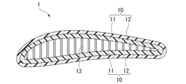
- FIG. 1 is a cross-sectional view of an unmanned aircraft wing that can be manufactured using a manufacturing method according to an embodiment.
- FIG. 2 shows a honeycomb core that can be used in the manufacturing method according to the embodiment.
- FIG. 2(A) is a perspective view
- FIG. 2(B) is a plan view.
- FIG. 3 is a cross-sectional view showing an example of how a mold for primary molding is charged with a honeycomb core and a first prepreg.
- FIG. 4 is a cross-sectional view showing an example of how a mold for primary molding is charged with a honeycomb core and a first prepreg.
- FIG. 5 is a cross-sectional view showing how a mold for secondary molding is charged with the primary molded product and the second prepreg.
- FIG. 1 is a cross-sectional view of an unmanned aircraft wing that can be manufactured using a manufacturing method according to an embodiment.
- FIG. 2 shows a honeycomb core that can be used in the manufacturing method according to
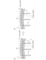
- FIG. 6 is a cross-sectional view schematically showing the inside of the mold during primary molding.
- FIG. 7 is a cross-sectional view schematically showing the inside of the mold during secondary molding.
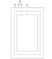
- FIG. 8 is a cross-sectional view showing an example of a portable mold that can be used in the manufacturing method according to the embodiment.
- FIG. 9 is a sectional view showing an example of a press machine that can be used in the manufacturing method according to the embodiment.
- FIG. 10 is a plan view showing the lower plate part of the press.
- FIG. 11 is a plan view (viewed from below) of the upper plate of the press.
- FIG. 12 is a cross-sectional view showing how the charged portable mold is pressurized by a press machine.
- FIG. 13 is a cross-sectional view showing an example of a press machine that can be used in the manufacturing method according to the embodiment.
- FIG. 14 is a cross-sectional view showing an example of a press machine that can be used in the manufacturing method according to the embodiment.
- FIG. 15 is an example of a binarized cross-sectional view of the fabric layer cross-section of the honeycomb sandwich structure according to Experimental Example 1.
- FIG. 16 is an example of a binarized cross-sectional view of the fabric layer cross-section of the honeycomb sandwich structure according to Experimental Example 2.
- FIG. 17 is an explanatory diagram showing the angle between the longitudinal direction of the fiber bundle cross section (the cross section of yarn B) and the reference line.
- FIG. 18 is an explanatory diagram of a CFRP layer including a fabric layer.
- FIG. 1 is a cross-sectional view of an unmanned aircraft wing that can be manufactured using a manufacturing method according to an embodiment.
- the blade 1 is a honeycomb sandwich structure, and has a structure in which a honeycomb core 13 is sandwiched between two CFRP layers 10, each consisting of a first CFRP layer 11 and a second CFRP layer 12.
- the honeycomb core 13 is processed into a predetermined shape by cutting or by a press disclosed in JP-A-2021-112849.
- the material of the metal foil constituting the honeycomb core 13 is an aluminum alloy (typically A5052, which is an Al-Mg aluminum alloy, or A3003, which is an Al-Mn aluminum alloy), but other metals, such as stainless steel. It may be.
- the cell size and thickness of the honeycomb core are defined as shown in FIG.
- the cell size d of the honeycomb core 13 is preferably 2 to 20 mm.
- the thickness of the metal foil constituting the honeycomb core 13 is preferably 20 to 120 ⁇ m.
- the maximum thickness C of the honeycomb core 13 is, for example, 1 to 50 mm, preferably 2 to 10 mm, and more preferably 2 to 7 mm.
- CFRP The material of the first CFRP layer 11 and the second CFRP layer 12 is CFRP.
- CFRP is a composite material in which a fiber reinforcement containing carbon fibers is impregnated with a cured thermosetting resin composition.
- the honeycomb core 13 may bite into the first CFRP layer 11, and in that case, the carbon fibers may be cut at the biting location.
- the honeycomb core 13 does not dig into the second CFRP layer 12, and the honeycomb core 13 does not cut the carbon fibers in the second CFRP layer 12.
- the first CFRP layer 11 may contain more voids than the second CFRP layer 12.
- the second CFRP layer 12 does not include voids, or if it does, the number of voids is small.
- honeycomb sandwich structure that can be manufactured using the manufacturing method according to the embodiment is not limited to wings for unmanned aircraft.
- the manufacturing method according to the embodiment can also be preferably used for manufacturing honeycomb sandwich structures used as parts and building materials for space equipment, home appliances, automobiles, ships, etc.
- specifications such as the material of the honeycomb core, cell size, foil thickness, maximum thickness, etc. are determined as appropriate depending on the use thereof.
- Honeycomb cores include not only metal honeycomb cores made of metals such as aluminum alloys and stainless steel, but also FRP (Fiber Reinforced Plastics) such as paper honeycomb cores and aramid honeycomb cores made of aramid fiber paper impregnated with phenolic resin.
- a honeycomb core fiber-reinforced resin
- the honeycomb core is charged into a mold together with the first prepreg in a flat plate shape, and then molded together with the first prepreg into a desired shape by pressing. After processing the honeycomb core into a desired shape or a state close to the desired shape in advance, the first prepreg and the mold may be charged.
- the first prepreg is hardened by primary molding, and then the second prepreg is hardened by secondary molding.
- primary molding the first prepreg is pressed against the mold by the honeycomb core, so there are parts of the first prepreg that are pressed against the mold and parts that are not pressed.
- secondary molding the second prepreg is pressed against the mold with the entire surface of the cured first molded product, so that disturbances in the orientation of the fiber reinforcing material can be reduced.
- a honeycomb sandwich structure manufactured using the manufacturing method according to an example of the embodiment is a structure in which a honeycomb core is sandwiched between CFRP layers, and the CFRP layer includes a woven fabric layer having a woven fiber reinforcement material.
- the standard deviation of the distance between the textile threads of each divided layer which is determined by the following measuring method for the textile layer, is 30 ⁇ m or less. (Measurement method of standard deviation of distance)
- a cross section cut in the orthogonal direction of the thread B in the CFRP layer is imaged, and the cross section is converted into a binary value using image processing software ImageJ. , and calculate the center of gravity position of the cross section of each yarn B.
- the shortest distance from the center of gravity to the outer surface of the honeycomb sandwich structure for each of the five adjacent yarns B finds the distance and calculate its standard deviation. Note that it is usually not known which of the orthogonal textile threads in the fabric in the CFRP layer is the warp and which is the weft, but either the warp or the weft may be used as thread A or thread B, and in either case, the above-mentioned distance
- the standard deviation is 30 ⁇ m or less.
- the standard deviation of the distances measured for the fabric yarns of each divided layer of each fabric layer is all 30 ⁇ m or less. If the standard deviation of the distance is 30 ⁇ m or less, the textile threads are arranged along the outer surface of the honeycomb sandwich structure, and the strength of the honeycomb sandwich structure tends to be uniform. From these viewpoints, the standard deviation of the distance is preferably 25 ⁇ m or less, more preferably 20 ⁇ m or less.
- the fabric layer may be provided on at least one of the CFRP layers sandwiching the honeycomb core. Moreover, it is preferable that the fabric layer is located in the CFRP layer closest to the honeycomb core side in the CFRP layer. Since the fabric layer disposed on the CFRP layer closest to the honeycomb core side is pressed against the mold in the thickness direction of the honeycomb core, disorder of the fibers tends to be reduced. Apart from the position closest to the honeycomb core, the textile layer is also preferably the outermost layer of the CFRP layer. It is easy to improve the appearance by placing it on the outermost layer. In a CFRP layer including a woven fabric layer, the woven fiber reinforcement may be combined with a unidirectional (UD) fibrous reinforcement or a nonwoven fibrous reinforcement. It may be used depending on the desired physical properties.
- UD unidirectional
- FIG. 18 is an explanatory diagram showing a CFRP layer including four fabric layers as an example of a CFRP layer including fabric layers.
- the divided layer of the fabric layer means each layer when, in each fabric layer, the yarn B on the surface layer side of the yarn A is used as the A layer, and the yarn B on the honeycomb core side of the yarn A is divided as the B layer.
- Each fabric layer in FIG. 18 is 1st layer, 2nd layer, 3rd layer, and 4th layer from the surface layer side, "1A” means A layer in 1st layer, "1B” means B layer in 1st layer, 2A, 2B, The same applies to 3A, 3B, 4A, and 4B.
- a small piece is cut out from the honeycomb sandwich structure, in which a cross section of the structure including the fabric layer can be observed, perpendicular to the yarn B of the fabric. After embedding it in epoxy resin, the cross section is cut out using a rotary polishing machine (Struers Co., Ltd.). A sample was prepared by polishing with Degramin-25, #4000 (manufactured by Degramin Co., Ltd.). The polished cross section is imaged using a laser microscope (manufactured by Keyence Corporation, VHX-8000) at a magnification of 80 times.
- the distance per pixel is obtained from the scale bar of the cross-sectional observation image using image processing software, and the coordinates are converted from pixel number to length scale, and then the honeycomb sandwich structure is The outer surface of is approximated by a line or spline curve to obtain the outer surface curve.
- the contour of the fiber bundle (thread B) oriented in a direction perpendicular to the image plane is approximated by a spline curve, and a cross section of the fiber bundle (thread B) is extracted by binarization processing. From the cross sections of all the extracted yarns B, the standard deviation of the shortest distance from the center of gravity coordinates (center of gravity position) to the outer surface is obtained for five adjacent yarns B of each divided layer.
- the method of converting coordinates from pixel numbers to length scales using the image processing software ImageJ and the method of obtaining the outer surface curve of the honeycomb sandwich structure are also employed in the measurement method described below.
- a honeycomb sandwich structure manufactured using the manufacturing method according to an example of the embodiment is a structure in which a honeycomb core is sandwiched between CFRP layers, and at least one of the CFRP layers sandwiching the honeycomb core has a honeycomb structure.
- a fabric layer having a fabric fiber reinforcement is arranged in the CFRP layer closest to the core side, and the standard deviation of the distance for the fabric yarns of each divided layer is determined for the fabric layer by the following measurement method. is 30 ⁇ m or less.
- the standard deviation of the distance determined for the fabric yarns of the fabric layer closest to the honeycomb core side is 30 ⁇ m or less, the fabric located in the fabric layer closest to the honeycomb core side will be uniform along the outer surface of the honeycomb sandwich structure.
- the honeycomb sandwich structure tends to have uniform strength. From these viewpoints, the standard deviation of the distance in the fabric layer closest to the honeycomb core side is preferably 25 ⁇ m or less, more preferably 20 ⁇ m or less.
- a honeycomb sandwich structure manufactured using the manufacturing method according to an example of the embodiment is a structure in which a honeycomb core is sandwiched between CFRP layers, and the CFRP layer includes a woven fabric layer having a woven fiber reinforcement material. and the standard deviation of the angle determined by the following measuring method for the textile yarns of the textile layer is 1.5 degrees or less. If the CFRP layer includes multiple fabric layers, the standard deviation of the angles measured for the fabric yarns of each fabric layer are all 1.5 degrees or less. If the standard deviation of the angle is 1.5 degrees or less, the surface of the fabric is arranged along the outer surface of the honeycomb sandwich structure, and the strength of the honeycomb sandwich structure is likely to be uniform. From these viewpoints, the standard deviation of the angle is preferably 1.2 degrees or less, more preferably 1.0 degrees or less.
- a honeycomb sandwich structure manufactured using the manufacturing method according to an example of the embodiment is a structure in which a honeycomb core is sandwiched between CFRP layers, and the outer surface of the honeycomb sandwich structure is determined by the following measurement method.
- a value A obtained by dividing the standard deviation D A ( ⁇ m) of the distance between and the innermost surface of the CFRP layer by the average value D B ( ⁇ m) of the distance is 0.01 or more and 0.10 or less.
- Method for measuring the standard deviation and average value of the distance between the outer surface and the innermost surface A cross section of the thickest part of the honeycomb sandwich structure is taken in parallel to the thickness direction of the honeycomb core, and the cross section is binarized using image processing software ImageJ.
- the outer surface coordinates of the honeycomb sandwich structure and the innermost surface coordinates of the CFRP layer are acquired for each pixel. For each point on the outer surface coordinates, measure the distance between the outer surface coordinates and the innermost coordinate located in the normal direction to the outer surface in the outer surface coordinates, and calculate the standard deviation DA of the distance and the Calculate the average distance value DB .
- the thickness of the prepreg in the first stage can be reduced, so even when the prepreg is pressed by the honeycomb core, the straightness of the prepreg is easily maintained. , the value A can be made smaller. Due to the small variation in the thickness of the CFRP layer, the rigidity of the honeycomb sandwich structure is high. It is a characteristic of two-stage molding that the value A is 0.01 or more and 0.10 or less.
- a honeycomb sandwich structure manufactured using a manufacturing method includes a CFRP layer (fabric layer) having a woven fiber reinforcement, and a CFRP layer (a UD) having a unidirectional (UD) fiber reinforcement. layer). Including the fabric layer can prevent the honeycomb sandwich structure from cracking, and including the UD layer can increase the rigidity in a specific direction.
- the UD layer is arranged adjacent to the outer surface side of the honeycomb sandwich structure rather than the textile layer, and the following measurement method is used.
- the value obtained by dividing the standard deviation D C ( ⁇ m) of the distance from the outer surface of the honeycomb sandwich structure to the interface between the textile layer and the UD layer by the average value D D ( ⁇ m) of the distance, which is calculated by B is 0.01 or more and 0.10 or less.
- a cross section of the thickest part of the honeycomb sandwich structure is taken in parallel to the thickness direction of the honeycomb core, and the cross section is binarized using image processing software ImageJ.
- ImageJ image processing software
- the outer surface coordinates of the honeycomb sandwich structure and the interface coordinates between the textile layer and the UD layer are acquired for each pixel. do.
- For each point on the outer surface coordinates measure the distance between the outer surface coordinates and the interface coordinate located in the normal direction to the outer surface at the outer surface coordinates, and calculate the standard deviation of the distance D C and the Calculate the average distance value D.
- the straightness of each layer is improved, so the rigidity of the honeycomb sandwich structure is increased. It is a characteristic of two-stage molding that the value B is 0.01 or more and 0.10 or less.
- the materials include a honeycomb core that is flat or processed into a predetermined shape by cutting or pressing (method disclosed in JP-A-2021-112849), and at least two first prepregs.
- the first prepreg is a sheet made of a reinforcing material made of carbon fiber and a thermosetting resin matrix.
- the resin matrix is preferably an epoxy resin composition.
- first prepregs include, but are not limited to, UD prepregs, woven prepregs, nonwoven prepregs, and sheet molding compounds (SMC).
- the at least two first prepregs include at least one of a UD prepreg and a textile prepreg.
- a primary molding mold 20 is charged with a honeycomb core 13 and at least two first prepregs 14.
- the honeycomb core 13 and at least two first prepregs 14 are placed in the molding cavity formed when the primary molding mold 20 consisting of the lower mold 21 and the upper mold 22 is closed. put.
- the honeycomb core 13 is arranged in the molding cavity so that the thickness direction is the vertical direction, and at least one first prepreg 14 is arranged above and below the honeycomb core 13, that is, on each of both sides of the honeycomb surface.
- FIG. 3 shows an embodiment using a honeycomb core 13 that has been processed in advance into a desired shape or a state close to the desired shape
- FIG. 4 shows an embodiment using a flat honeycomb core 13.
- a mold release agent it is preferable to apply a mold release agent to the portion of the mold 20 for primary molding that will form the molding cavity. By applying a mold release agent, the primary molded product can be easily taken out from the mold 20 for primary molding.
- the number of first prepregs arranged above and below the honeycomb core is preferably 1 or more and 5 or less, more preferably 3 or less.
- the number of first prepregs is preferably three or less.
- the number of first prepregs is preferably 5 or more and 30 or less.
- the end portion of the first prepreg 14 disposed below the honeycomb core 13 may wrap around the top of the honeycomb core 13.
- the end portion of the first prepreg 14 disposed on the honeycomb core 13 may wrap under the honeycomb core 13.
- the thickness direction of the honeycomb core 13 refers to the height direction of a plurality of hexagonal columnar cells included in the honeycomb core 13.
- the type and number of the first prepregs 14 arranged below the honeycomb core 13 and the first prepregs 14 arranged above the honeycomb core 13 may be the same or different.
- two or more UD prepregs are stacked as the first prepreg 14 under the honeycomb core 13, they may be stacked so that the fiber directions match, or they may be cross-ply or angle-ply stacked. .
- An adhesive film can be placed between the honeycomb core 13 and the first prepreg 14.
- the partially arranged prepreg is preferably a UD prepreg, and it is preferable from the viewpoint of bending rigidity that the fiber direction of the UD prepreg is oriented in the longer direction of the structure.
- the first prepreg is cured and a primary molded product is obtained.
- the charged primary forming mold 20 is pressurized and heated using a press machine to shape the honeycomb core into the desired shape. While curing the first prepreg, a primary molded product is obtained.
- the first prepreg can be arranged with the honeycomb core in a flat state, the first prepreg is easy to arrange and is less likely to wrinkle.
- the first prepreg can also be uniformly pressurized by the honeycomb core.
- the primary molded product is a honeycomb sandwich structure in which a honeycomb core is sandwiched between two first CFRP layers.
- the first CFRP layer is a cured product of the first prepreg.
- the molding temperature may be 110°C or more and 120°C or less, 120°C or more and 135°C or less, 135°C or more and 145°C or less, 145°C or more and 150°C or less, 150°C or more and 180°C or less.
- the second prepreg is a sheet made of a reinforcing material made of carbon fiber and a thermosetting resin matrix.
- the resin matrix is preferably an epoxy resin composition.
- second prepregs include, but are not limited to, UD prepregs, woven prepregs, nonwoven prepregs, and sheet molding compounds (SMC).
- the at least two second prepregs include at least one of a UD prepreg and a textile prepreg.
- the outermost prepreg is preferably a woven prepreg because the fibers at the ends are less likely to be disturbed.
- a mold 30 for secondary molding is charged with the primary molded product 2 and at least two second prepregs 15.
- the primary molded product 2 and at least two second prepregs 15 are placed in the molding cavity formed when the secondary molding mold 30 consisting of the lower mold 31 and the upper mold 32 is closed.
- the mold 30 for secondary molding is different from the mold 20 for primary molding in that it is larger than the mold 20 for primary molding because it is thicker due to the laminated second prepreg.
- a mold release agent is applied to the mold during primary molding, the release agent adheres to the primary molded product and the adhesion with the second prepreg deteriorates. It is necessary to remove the molding agent.
- polishing by sandblasting or the like or degreasing treatment is performed.
- the primary molded product 2 is arranged in the molding cavity so that the thickness direction of the honeycomb core 13 included in the primary molded product 2 is in the vertical direction, and at least one sheet of second prepreg 15 is provided on each of the upper and lower sides of the primary molded product 2. is placed.
- the end of the second prepreg 15 disposed below the primary molded product 2 may wrap around onto the primary molded product 2.
- the end of the second prepreg 15 disposed on the primary molded product 2 may wrap under the primary molded product 2.
- the fiber reinforcing material of the second prepreg 15 is connected to the top and bottom of the primary molded product 2, so the strength of the molded product can be increased and a good appearance with no border between the top and bottom can be obtained. can.
- the type and number of the second prepreg 15 placed under the primary molded product 2 and the second prepreg 15 placed on the primary molded product 2 may be the same or different.
- they When arranging two or more UD prepregs as the second prepreg 15 under the primary molded product 2, they may be laminated so that the fiber directions match, or they may be cross-ply laminated or angle-ply laminated. good. The same applies when two or more UD prepregs are stacked and arranged on the primary molded product 2 as the second prepreg 15.
- the second prepreg is cured and a secondary molded product, that is, a desired molded product is obtained.
- the secondary molded product is a honeycomb sandwich structure in which a honeycomb core 13 is sandwiched between two first CFRP layers 11 and a second CFRP layer 12 laminated on each of them.
- the second CFRP layer is a cured product of the second prepreg.
- the press be heated to the molding temperature before charging of the secondary molding die is completed.
- the molding temperature may be 110°C or more and 130°C or less, 130°C or more and 135°C or less, 135°C or more and 145°C or less, 145°C or more and 150°C or less, 150°C or more and 180°C or less.
- the first prepreg 14 is placed between the honeycomb core 13 and the mold 20, as shown in FIG. 6 (left).
- the mold 20 is pressurized with a press machine, the first prepreg 14 is pressed against the surface of the mold 20 by the honeycomb core 13.
- FIG. 5 (right) only the edges of the metal foil constituting the honeycomb core 13 are in contact with the first prepreg 14, so the entire first prepreg 14 is not evenly pressed against the surface of the mold 20. . Therefore, the shape of the mold 20 (the shapes of the surfaces 21a and 22a of the lower mold 21 and the upper mold 22, respectively) is not sufficiently reflected in the surface shape of the first CFRP layer 11.
- the honeycomb core 13 may dig into the first CFRP layer 11, and the carbon fibers may be cut accordingly.
- the second prepreg 15 is placed between the primary molded product 2 and the mold 30, as shown in FIG. 7 (left). As shown in FIG. 7 (right), when the mold 30 is pressurized with a press machine, the second prepreg 15 is pressed against the surface of the mold 30 by the first CFRP layer 11 of the primary molded product 2. Since the entire surface of the first CFRP layer 11 is in contact with the second prepreg 15, the entire second prepreg 15 is uniformly pressurized. As a result, the shape of the mold 30 (the shapes of the surfaces 31a and 32a of the lower mold 31 and the upper mold 32, respectively) is sufficiently reflected in the surface shape of the second CFRP layer 12. Furthermore, voids are less likely to occur inside the second CFRP layer 12. Furthermore, in the second CFRP layer 12, cutting of the carbon fibers due to biting of the honeycomb core does not occur.
- a honeycomb sandwich structure can be obtained in two steps and can be efficiently produced. Furthermore, since the second prepreg can be uniformly pressed between the cured first CFRP layer and the mold, it is possible to reduce thickness unevenness and distortion of the second CFRP layer, and increase rigidity.
- Preferred embodiment (1) Use of portable mold 2.
- a portable mold at least in the secondary forming, preferably in both the primary forming and the secondary forming.
- the portable mold can be charged outside the press machine, for example, in a room at a temperature of 17 to 28°C.
- the temperature of the portable mold during charging is preferably the same as the working environment temperature.
- a portable mold that has been heated for the purpose of drying after cleaning may be charged before the temperature drops to the working environment temperature, but even in that case, the prepreg should not wrinkle during handling. Therefore, it is preferable to wait until the temperature of the portable mold becomes 40° C. or less before charging.
- the temperature of the portable mold is low, below 40°C or even below 28°C, even if it takes a long time to charge, the temperature of the prepreg will not rise during that time and the surface tackiness will not become strong. Therefore, wrinkles are less likely to occur in the prepreg.
- the temperature of the portable mold after preheating is preferably 40°C or more and 80°C or less, more preferably 60°C or more and 80°C or less. If the temperature of the portable mold is 80° C. or lower, it can be touched with gloved hands, so there is no problem in transporting it.
- the material of the portable mold is carbon steel or alloy steel (steel to which chromium, molybdenum, tungsten, vanadium, etc. are added), which are conventionally used as steel materials for plastic molding. Good too.
- more preferable materials are aluminum alloy or beryllium copper. These alloys have a high thermal conductivity of 100 W/(m ⁇ K) or more at 20°C.
- Aluminum alloys are particularly preferred because they have high thermal conductivity and are lightweight.
- the specific gravity at 20°C is around 7.9 for steel and over 8 for beryllium copper, whereas it is usually 2.7 to 2.8 for aluminum alloy.
- Examples of aluminum alloys include 7000 series aluminum alloy (Al-Zn-Mg alloy), which is said to have the highest strength among aluminum alloys, and 2000 series aluminum alloy (Al-Cu alloy), which has strength comparable to steel. ), including but not limited to.
- the thermal conductivity of aluminum alloys varies depending on tempering, but the thermal conductivity at 20°C is 130 to 190 W/(m ⁇ K) for A2017 (duralumin), 150 W/(m ⁇ K) for A7003, and 150 W/(m ⁇ K) for A7075 (super).
- Super duralumin) is said to have a power of 130W/(m ⁇ K).
- chromium-molybdenum steel which has relatively high thermal conductivity, has a thermal conductivity of approximately 60 W/(m ⁇ K) at 20°C, and the thermal conductivity of carbon steel is higher than this. low.
- the weight of the portable mold may preferably be 2 kg or more and 30 kg or less. It is convenient for the weight to be within this range for transporting the portable mold. However, the weight of the portable mold is not limited to this range.
- the portable mold may be composed of a lowermost plate 40, an uppermost plate 50, and an intermediate plate 60, as shown in FIG. 8 as an example.
- the number of intermediate plates is not limited to three, and may be two or less, or four or more.
- the planar shape of each plate is, for example, rectangular. If desired, handles can be attached to the sides of any plate. All the plates have the same outer shape and outer dimensions in plan view, and can be perfectly overlapped with each other.
- an alignment convex portion and an alignment concave portion may be provided on one and the other of adjacent plates, respectively, so that the two plates fit together only when the two plates are stacked so as to overlap exactly.
- the lower surface of the lowermost plate and the upper surface of the uppermost plate are both entirely flat. When all the plates are stacked, the bottom surface of the bottom plate and the top surface of the top plate are parallel to each other. In one example, multiple mold cavities may be formed between adjacent plates. In one example, at least a portion of the plate constituting the portable mold may have an insert structure and may be composed of a mother mold and a nest mold.
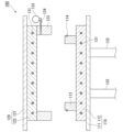
- FIG. 9 shows an example of a press machine that can reduce the pressure in the space around the portable die when heating and pressurizing the portable die.
- the press machine 100 moves a lower plate part 110, an upper plate part 120 disposed above the lower plate part 110 facing the lower plate part 110, and a direction in which the lower plate part 110 and the upper plate part 120 are moved closer to each other.
- a pressure mechanism (only the cylinder 132 of the pressure mechanism is shown in FIG. 9) is provided.
- the lower plate portion 110 includes a lower substrate 111 arranged horizontally and a lower heating plate 112 attached to the upper surface side of the lower substrate 111.
- the upper plate part 120 includes an upper substrate 121 arranged horizontally and an upper heating plate 122 attached to the lower surface side of the upper substrate 121.
- FIG. 9 illustration of a frame for fixing the upper plate portion 120 and the like is omitted.
- the pressurizing mechanism is preferably a hydraulic type because it is easy to control the pressure.
- the cylinder 132 of the pressurizing mechanism may be arranged so as to act on the upper plate part 120 instead of the lower plate part 110.
- the lower heating plate 112 and the upper heating plate 122 each have a built-in heater 131. Examples of heaters 131 include, but are not limited to, steam heaters, oil heaters, electric heaters, and electromagnetic induction heaters.
- An annular lower wall member 113 is fixed to the upper surface of the lower heating plate 112. As shown in a plan view in FIG. 10, the lower wall member 113 has a structure in which four vertical walls, each perpendicular to the upper surface of the lower heating plate 112, are connected to form a rectangular ring. It is arranged slightly inside the circumferential surface of the board 112. The lower heating plate 112 and the lower wall member 113 may be seamlessly integrated.
- the lower wall member 113 is provided with a groove that goes around its outer circumferential surface, and a vacuum sealing ring 114 is fitted into the groove.
- An annular upper wall member 123 is fixed to the lower surface of the upper heating plate 122.
- the upper wall member 123 has a structure in which four vertical walls, each perpendicular to the lower surface of the upper heating plate 122, are connected to form a rectangular ring. and is arranged along the circumferential surface of the upper heating plate 122.
- the upper heating plate 122 and the upper wall member 123 may be seamlessly integrated.
- the upper wall member 123 is provided with an exhaust hole 124 passing through one of the vertical walls.
- the exhaust hole 124 is connected to a vacuum pump 133.
- the pressure in the closed space S is reduced by operating the vacuum pump 133 so that the pressure after pressure reduction is preferably 0.1 Pa or less, more preferably 0.01 Pa or less.
- the pressure after pressure reduction is preferably 0.1 Pa or less, more preferably 0.01 Pa or less.
- the lower wall member 113 may be omitted and the lower heating plate 112 and the upper wall member 123 may be fitted together via a vacuum sealing ring 114. good.
- FIG. In another variation of the press, as shown in FIG. may be fixed respectively.
- the configuration of the press machine in which a closed space capable of reducing pressure is formed between the lower heating plate and the upper heating plate is not limited to the above-mentioned example.
- FIGS. 12 to 14 a transportable mold is shown that does not have an intermediate plate and consists only of a lower mold (lowermost plate 40) and an upper mold (uppermost plate 50), but it has an intermediate plate. Can be replaced with a portable mold.
- a method of manufacturing a honeycomb sandwich structure comprising: [Embodiment 2] The method for manufacturing a honeycomb sandwich structure according to Embodiment 1, wherein at least one of the at least two first prepregs is arranged on each of both sides of the honeycomb surface of the honeycomb core. [Embodiment 3] A manufacturing method according to Embodiment 2, wherein the number of first prepregs arranged on each of both surfaces of the honeycomb surface of the honeycomb core is one to five.
- Embodiment 4 The manufacturing method according to Embodiment 2, wherein the number of first prepregs arranged on each of both surfaces of the honeycomb surface of the honeycomb core is 5 or more and 30 or less.
- Embodiment 5 The manufacturing method according to any one of Embodiments 1 to 4, including a portion where the number of the first prepregs is partially large.
- Embodiment 6 The manufacturing method according to any one of Embodiments 1 to 5, wherein the honeycomb core is pressurized with a press to obtain a desired shape.
- the secondary molding mold is a portable mold.
- Embodiment 8 A manufacturing method according to Embodiment 7, wherein the material of the portable mold is an aluminum alloy.
- Embodiment 9 The manufacturing method according to Embodiment 7 or 8, wherein the temperature of the secondary molding mold is 40° C. or less when charging the secondary molding mold.
- Embodiment 10 The manufacturing method according to Embodiment 9, wherein charging of the mold for secondary molding is performed indoors at a temperature of 17 to 28°C.
- Emodiment 11 The manufacturing method according to any one of Embodiments 7 to 10, wherein the mold for primary molding is a portable mold.
- Embodiment 12 A manufacturing method according to Embodiment 11, wherein the material of the portable mold is an aluminum alloy.
- Embodiment 13 The manufacturing method according to Embodiment 11 or 12, wherein the temperature of the primary molding mold is 40° C. or lower when charging the primary molding mold.
- Embodiment 14 The manufacturing method according to Embodiment 13, wherein charging of the mold for primary molding is performed indoors at a temperature of 17 to 28°C.
- Embodiment 15 Any one of Embodiments 7 to 14, wherein the space around the secondary forming mold is depressurized when the charged secondary forming mold is pressurized and heated with a press machine. Manufacturing method related to crab.
- Embodiment 16 A manufacturing method according to Embodiment 15, wherein when the charged primary molding mold is pressurized and heated with a press machine, the space around the secondary molding mold is depressurized.
- Embodiment 17 A structure in which a honeycomb core is sandwiched between CFRP layers, A honeycomb sandwich structure whose value A determined by the following measurement method is 0.01 or more and 0.10 or less. (Method of measuring value A) A cross section of the thickest part of the honeycomb sandwich structure is taken in parallel to the thickness direction of the honeycomb core.
- the outer surface coordinates of the honeycomb sandwich structure and the innermost inner surface coordinates of the CFRP layer were determined for each pixel in a 20 mm range in the direction perpendicular to the thickness direction of the honeycomb core in the cross-sectional image. get.
- measure the distance between the outer surface coordinates and the innermost coordinate located in the normal direction to the outer surface in the outer surface coordinates and calculate the standard deviation DA of the distance and the The average distance value D B is calculated, and the value A is obtained from the following formula (1).
- the CFRP layer includes a woven layer that is a CFRP layer with woven fiber reinforcement, and a UD layer that is a CFRP layer with unidirectional (UD) fibrous reinforcement.
- a honeycomb sandwich structure Such a honeycomb sandwich structure.
- the UD layer is arranged adjacent to the outer surface of the honeycomb sandwich structure than the textile layer, and the value B determined by the following measurement method is 0.01 or more and 0.10 or less.
- the honeycomb sandwich structure according to Embodiment 18. (Method of measuring value B) A cross section of the thickest part of the honeycomb sandwich structure is taken in parallel to the thickness direction of the honeycomb core.
- the outer surface coordinates of the honeycomb sandwich structure and the interface coordinates between the fabric layer and the UD layer are determined in a 20 mm range in the direction perpendicular to the thickness direction of the honeycomb core in the image of the cross section. and is obtained for each pixel.
- For each point on the outer surface coordinates measure the distance between the outer surface coordinates and the interface coordinate located in the normal direction to the outer surface at the outer surface coordinates, and calculate the standard deviation of the distance D C and the The average value DD of the distance is calculated, and the value B is obtained from the following formula (2).
- a cross section cut in the orthogonal direction of the thread B in the CFRP layer is imaged, and the cross section is converted into a binary value using image processing software ImageJ.
- a cross section cut in the orthogonal direction of the thread B in the CFRP layer is imaged, and the cross section is converted into a binary value using image processing software ImageJ. , and calculate the center of gravity position of the cross section of each yarn B.
- the outer surface at the point of closest proximity to the yarn B on the long axis direction of the elliptical approximation of the cross section of the yarn B and the outer surface curve of the honeycomb sandwich structure For each of the ten yarns B adjacent to each other in the textile layer, the outer surface at the point of closest proximity to the yarn B on the long axis direction of the elliptical approximation of the cross section of the yarn B and the outer surface curve of the honeycomb sandwich structure. Find the angle between the tangent line and a reference line that is parallel to and passes through the center of gravity of the thread B, and calculate its standard deviation.
- Example 1 An aluminum alloy honeycomb core and eight fabric prepreg sheets were prepared.
- a mold for primary forming was charged with a honeycomb core and a first prepreg, which was a woven fabric prepreg placed one above and one above the honeycomb core. By pressurizing and heating using a press machine, the first prepreg was cured to obtain a primary molded product.
- a mold for secondary molding was charged with a primary molded product and a second prepreg, which was a woven fabric prepreg, and three sheets were placed above and below the primary molded product. The second prepreg was cured by applying pressure and heating using a press to obtain a honeycomb sandwich structure.
- Example 2 An aluminum alloy honeycomb core and eight fabric prepreg sheets were prepared. A mold for secondary forming was charged with a honeycomb core and four fabric prepregs placed above and below the honeycomb core. The woven prepreg was cured by applying pressure and heat using a press to obtain a honeycomb sandwich structure.
- FIGS. 15 and 16 show binarized cross-sectional views of the fabric layer when determining the standard deviation.
- Example 3 An aluminum alloy honeycomb core, four fabric prepregs, and two UD prepregs were prepared.
- a mold for primary molding was charged with a honeycomb core and a first prepreg, which is a UD prepreg, one sheet each placed above and below the honeycomb core. By pressurizing and heating using a press machine, the first prepreg was cured to obtain a primary molded product.
- a mold for secondary molding was charged with a primary molded product and a second prepreg, which was a woven fabric prepreg, two sheets each of which were placed above and below the primary molded product. The second prepreg was cured by applying pressure and heating using a press to obtain a honeycomb sandwich structure.
- Example 4 An aluminum alloy honeycomb core, 46 pieces of UD prepreg, and 6 pieces of woven fabric prepreg were prepared.
- a mold for primary forming was charged with a honeycomb core and a first prepreg in which 21 sheets of UD prepreg and 2 sheets of woven fabric prepreg were arranged on the upper and lower sides of the honeycomb core, respectively. By pressurizing and heating using a press machine, the first prepreg was cured to obtain a primary molded product.
- a mold for secondary molding was charged with the primary molded product and a second prepreg in which two UD prepregs and one fabric prepreg were arranged above and below the primary molded product in this order. The second prepreg was cured by applying pressure and heating using a press to obtain a honeycomb sandwich structure.
- Example 5 An aluminum alloy honeycomb core, four fabric prepregs, and two UD prepregs were prepared. A mold for molding was arranged with a honeycomb core, one UD prepreg above and below the honeycomb core, and two fabric prepregs each. The prepreg was cured by applying pressure and heating using a press to obtain a honeycomb sandwich structure.
- the standard deviation DA of the distance between the outer surface of the honeycomb sandwich structure and the innermost surface of the CFRP layer was divided by the average value DB of the distance using the method described above.
- Table 3 shows the results of determining the value A.
- the standard deviation D C of the distance between the outer surface of the honeycomb sandwich structure and the interface between the fabric layer and the UD layer was determined by the method described above.
- Table 3 also shows the value B divided by the average value D of distance.
Landscapes
- Engineering & Computer Science (AREA)
- Mechanical Engineering (AREA)
- Chemical & Material Sciences (AREA)
- Composite Materials (AREA)
- Textile Engineering (AREA)
- Laminated Bodies (AREA)
Priority Applications (2)
| Application Number | Priority Date | Filing Date | Title |
|---|---|---|---|
| EP23857426.3A EP4578619A4 (en) | 2022-08-24 | 2023-08-24 | A METHOD FOR MANUFACTURED A HONEYCOMB SANDWICH STRUCTURE AND SAID STRUCTURE |
| JP2024542879A JPWO2024043318A1 (https=) | 2022-08-24 | 2023-08-24 |
Applications Claiming Priority (4)
| Application Number | Priority Date | Filing Date | Title |
|---|---|---|---|
| JP2022-133293 | 2022-08-24 | ||
| JP2022133293 | 2022-08-24 | ||
| JP2023-070926 | 2023-04-24 | ||
| JP2023070926 | 2023-04-24 |
Publications (1)
| Publication Number | Publication Date |
|---|---|
| WO2024043318A1 true WO2024043318A1 (ja) | 2024-02-29 |
Family
ID=90013495
Family Applications (1)
| Application Number | Title | Priority Date | Filing Date |
|---|---|---|---|
| PCT/JP2023/030582 Ceased WO2024043318A1 (ja) | 2022-08-24 | 2023-08-24 | ハニカムサンドイッチ構造体の製造方法およびその構造体 |
Country Status (3)
| Country | Link |
|---|---|
| EP (1) | EP4578619A4 (https=) |
| JP (1) | JPWO2024043318A1 (https=) |
| WO (1) | WO2024043318A1 (https=) |
Citations (7)
| Publication number | Priority date | Publication date | Assignee | Title |
|---|---|---|---|---|
| US20010046600A1 (en) * | 1999-03-23 | 2001-11-29 | Hexcel Corporation | Core-crush resistant fabric and prepreg for fiber reinforced composite sandwich structures |
| US20080233344A1 (en) * | 2006-02-07 | 2008-09-25 | Burkhart Grob | Airplane component as well as method for manufacturing an airplane component |
| JP2008230235A (ja) * | 2007-02-22 | 2008-10-02 | Toray Ind Inc | サンドイッチ構造体、およびそれを用いた成形体、電子機器筐体 |
| JP2010524779A (ja) * | 2008-01-31 | 2010-07-22 | ハンクック ファイバー グラス シーオー リミテッド | 運送車両用の一体型複合素材からなる車体及びその製造方法 |
| JP2021112849A (ja) | 2020-01-17 | 2021-08-05 | 株式会社チャレンヂ | 積層体及び積層体の製造方法 |
| JP2022133293A (ja) | 2018-03-20 | 2022-09-13 | シャープ株式会社 | 情報処理システム、及び情報処理方法 |
| JP2023070926A (ja) | 2021-11-10 | 2023-05-22 | 株式会社リコー | 給送装置、及び、画像形成装置 |
Family Cites Families (9)
| Publication number | Priority date | Publication date | Assignee | Title |
|---|---|---|---|---|
| JP2009166487A (ja) * | 2007-12-18 | 2009-07-30 | Nichigo Morton Co Ltd | 平面プレス装置および積層装置ならびにそれらを用いた積層方法 |
| JP2013022835A (ja) * | 2011-07-21 | 2013-02-04 | Mitsubishi Heavy Ind Ltd | 繊維強化樹脂を備える製品を少なくとも2つ製造する方法および装置 |
| JP6075094B2 (ja) * | 2012-02-07 | 2017-02-08 | 東レ株式会社 | リブ構造を有する成形品の製造方法 |
| JP6462864B2 (ja) * | 2014-06-04 | 2019-01-30 | ブライト ライト ストラクチャーズ エルエルシー | エネルギ吸収を示し、かつ/または欠陥が存在しない表面を含む複合材構造 |
| JP2016112844A (ja) * | 2014-12-17 | 2016-06-23 | 三菱重工業株式会社 | サンドイッチ構造の製造方法及びプリプレグの性能評価方法 |
| JP6581875B2 (ja) * | 2015-10-06 | 2019-09-25 | 三菱重工業株式会社 | 複合材の成形方法 |
| US12053963B2 (en) * | 2018-11-19 | 2024-08-06 | Bright Lite Structures Llc | High-strength low-heat release composites |
| JP6725027B2 (ja) * | 2019-03-14 | 2020-07-15 | 王子ホールディングス株式会社 | 多層成形品、及び多層成形品用シート |
| EP4228886A4 (en) * | 2020-10-16 | 2024-10-09 | Bright Lite Structures LLC | STRUCTURES WITH REGULATED HEAT RELEASE |
-
2023
- 2023-08-24 JP JP2024542879A patent/JPWO2024043318A1/ja active Pending
- 2023-08-24 EP EP23857426.3A patent/EP4578619A4/en active Pending
- 2023-08-24 WO PCT/JP2023/030582 patent/WO2024043318A1/ja not_active Ceased
Patent Citations (7)
| Publication number | Priority date | Publication date | Assignee | Title |
|---|---|---|---|---|
| US20010046600A1 (en) * | 1999-03-23 | 2001-11-29 | Hexcel Corporation | Core-crush resistant fabric and prepreg for fiber reinforced composite sandwich structures |
| US20080233344A1 (en) * | 2006-02-07 | 2008-09-25 | Burkhart Grob | Airplane component as well as method for manufacturing an airplane component |
| JP2008230235A (ja) * | 2007-02-22 | 2008-10-02 | Toray Ind Inc | サンドイッチ構造体、およびそれを用いた成形体、電子機器筐体 |
| JP2010524779A (ja) * | 2008-01-31 | 2010-07-22 | ハンクック ファイバー グラス シーオー リミテッド | 運送車両用の一体型複合素材からなる車体及びその製造方法 |
| JP2022133293A (ja) | 2018-03-20 | 2022-09-13 | シャープ株式会社 | 情報処理システム、及び情報処理方法 |
| JP2021112849A (ja) | 2020-01-17 | 2021-08-05 | 株式会社チャレンヂ | 積層体及び積層体の製造方法 |
| JP2023070926A (ja) | 2021-11-10 | 2023-05-22 | 株式会社リコー | 給送装置、及び、画像形成装置 |
Non-Patent Citations (1)
| Title |
|---|
| See also references of EP4578619A4 |
Also Published As
| Publication number | Publication date |
|---|---|
| EP4578619A1 (en) | 2025-07-02 |
| JPWO2024043318A1 (https=) | 2024-02-29 |
| EP4578619A4 (en) | 2025-12-03 |
Similar Documents
| Publication | Publication Date | Title |
|---|---|---|
| Albert et al. | Spring-in and warpage of angled composite laminates | |
| CN101570064B (zh) | 用于制造纤维增强层压件和横向延伸材料的方法 | |
| CN106232343B (zh) | 具有带有不对称树脂分布的可固化复合蒙皮的复合夹层板 | |
| JP6902753B2 (ja) | 炭素繊維強化樹脂部材の製造方法 | |
| KR102197337B1 (ko) | 안정화 부재를 구비한 복합 구조물 | |
| Hassan | A mini review on manufacturing defects and performance assessments of complex shape prepreg-based composites | |
| US20100080980A1 (en) | Molding process for core-containing composites and composites formed thereby | |
| CN102006993A (zh) | 用于制造在两侧带有覆盖层的芯复合部件的方法 | |
| US20100196654A1 (en) | Process for producing composite laminate structures and composite laminate structures formed thereby | |
| JP6583966B2 (ja) | 積層体からなるパネルおよびその製造方法 | |
| CN104999672A (zh) | 一种双曲率变截面变厚度通梁的成型方法 | |
| CN112223804A (zh) | 一种层合复合材料蜂窝的成型制备方法 | |
| CN102232037B (zh) | 飞行器的平面的结构部件和其加工方法 | |
| JP5698526B2 (ja) | 成形型 | |
| CN110475661B (zh) | 纤维罩纱用于减少蜂窝体夹层结构中的芯部压碎的用途 | |
| JP6823519B2 (ja) | 繊維強化複合材料成形体及びその製造方法 | |
| JP5786352B2 (ja) | 繊維強化樹脂板材の製造方法 | |
| WO2024043318A1 (ja) | ハニカムサンドイッチ構造体の製造方法およびその構造体 | |
| CN104385625B (zh) | 基于卸载孔的复合材料薄壁壳体制备方法 | |
| JP5958569B2 (ja) | 繊維強化樹脂板材の製造方法 | |
| EP3711935A1 (en) | Method and system for manufacturing a sub-component for a rotor blade of a wind turbine | |
| US20230323054A1 (en) | Reinforcement material for composite laminate | |
| CN209987489U (zh) | 一种槽型构件 | |
| Wu et al. | Fabrication and quality analysis of angle composite part by vacuum-bag-only process with interleaved woven fiber/prepreg layup | |
| US10899084B2 (en) | Methods for forming composite structures |
Legal Events
| Date | Code | Title | Description |
|---|---|---|---|
| 121 | Ep: the epo has been informed by wipo that ep was designated in this application |
Ref document number: 23857426 Country of ref document: EP Kind code of ref document: A1 |
|
| WWE | Wipo information: entry into national phase |
Ref document number: 2024542879 Country of ref document: JP |
|
| WWE | Wipo information: entry into national phase |
Ref document number: 2023857426 Country of ref document: EP |
|
| NENP | Non-entry into the national phase |
Ref country code: DE |
|
| ENP | Entry into the national phase |
Ref document number: 2023857426 Country of ref document: EP Effective date: 20250324 |
|
| WWP | Wipo information: published in national office |
Ref document number: 2023857426 Country of ref document: EP |