WO2024043264A1 - 端末、基地局及び通信方法 - Google Patents
端末、基地局及び通信方法 Download PDFInfo
- Publication number
- WO2024043264A1 WO2024043264A1 PCT/JP2023/030265 JP2023030265W WO2024043264A1 WO 2024043264 A1 WO2024043264 A1 WO 2024043264A1 JP 2023030265 W JP2023030265 W JP 2023030265W WO 2024043264 A1 WO2024043264 A1 WO 2024043264A1
- Authority
- WO
- WIPO (PCT)
- Prior art keywords
- band
- switching
- bands
- terminal
- transmission
- Prior art date
- Legal status (The legal status is an assumption and is not a legal conclusion. Google has not performed a legal analysis and makes no representation as to the accuracy of the status listed.)
- Ceased
Links
Images









Classifications
-
- H—ELECTRICITY
- H04—ELECTRIC COMMUNICATION TECHNIQUE
- H04W—WIRELESS COMMUNICATION NETWORKS
- H04W72/00—Local resource management
- H04W72/04—Wireless resource allocation
- H04W72/044—Wireless resource allocation based on the type of the allocated resource
- H04W72/0457—Variable allocation of band or rate
-
- H—ELECTRICITY
- H04—ELECTRIC COMMUNICATION TECHNIQUE
- H04W—WIRELESS COMMUNICATION NETWORKS
- H04W72/00—Local resource management
- H04W72/12—Wireless traffic scheduling
- H04W72/1263—Mapping of traffic onto schedule, e.g. scheduled allocation or multiplexing of flows
- H04W72/1268—Mapping of traffic onto schedule, e.g. scheduled allocation or multiplexing of flows of uplink data flows
Definitions
- the present disclosure relates to a terminal, a base station, and a communication method in a wireless communication system.
- the 3rd Generation Partnership Project (3GPP) specifies the 5th generation mobile communication system (5G, also known as New Radio (NR) or Next Generation (NG)), and also specifies the next generation called Beyond 5G, 5G Evolution or 6G. is also progressing.
- 5G also known as New Radio (NR) or Next Generation (NG)
- NG Next Generation
- Non-Patent Document 1 UL Tx switching schemes (across up to 3 or 4 bands with restriction of up to 2 Tx simultaneous transmission) are being considered.
- the present invention has been made to solve the above-mentioned problems, and provides a terminal that makes it possible to suppress complexity associated with UL Tx switching schemes while realizing flexible switching of bands used for UL transmission. , the purpose of providing base stations and communication methods.
- One aspect of the disclosure includes a transmitting unit that performs uplink transmission using N bands (N is a natural number of M or less), which are selected from M (M is a natural number of 3 or more) bands; , a control unit that controls the uplink transmission by securing a specific time that should be secured in order to switch the band used in the uplink transmission from a first band to a second band when a specific condition is satisfied. , is a terminal.
- One aspect of the disclosure includes a receiving unit that performs uplink reception using N (N is a natural number of M or less) bands selected from M (M is a natural number of 3 or more) bands; , a control unit that assumes the uplink reception that has secured a specific time to switch the band used in the uplink transmission from a first band to a second band when a specific condition is satisfied; It is a base station.
- One aspect of the disclosure includes the step of performing uplink transmission using N bands (N is a natural number equal to or less than M), which are selected from M (M is a natural number equal to or greater than 3) bands; and controlling the uplink transmission by securing a specific time to switch the band used in the uplink transmission from a first band to a second band when a specific condition is met. It's a method.
- FIG. 1 is a diagram for explaining a wireless communication system in an embodiment of the present invention.
- FIG. 1 is a diagram for explaining a wireless communication system in an embodiment of the present invention.
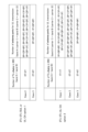
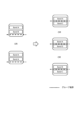
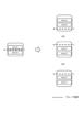
- FIG. 3 is a diagram showing case 1 and case 2 in UL Tx switching.
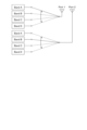
- FIG. 3 is a diagram illustrating a configuration example of an antenna port used for transmission in each case in UL Tx switching.
- FIG. 3 is a diagram illustrating a configuration example of an antenna port used for transmission and transmission in each case in UL Tx switching.
- FIG. 3 is a diagram showing an example of UE Capability.
- FIG. 3 is a diagram showing an example of RRC configuration.
- FIG. 3 is a diagram showing an example of a switching period.
- FIG. 3 is a diagram showing an example of a switching period.
- FIG. 3 is a diagram showing an example of a switching period.
- FIG. 3 is a diagram showing an example of the length of DL interruption.
- FIG. 3 is a diagram showing cases 1 to 3 in UL Tx switching.
- FIG. 3 is a diagram illustrating a configuration example of an antenna port used for transmission in each case in UL Tx switching.
- FIG. 3 is a diagram showing an example of RRC configuration.
- FIG. 3 is a diagram showing an example of a case where one band includes multiple carriers in UL Tx switching.
- FIG. 3 is a diagram illustrating a configuration example of an antenna port used for transmission in each case in UL Tx switching.
- FIG. 3 is a diagram illustrating a configuration example of an antenna port used for transmission in each case in UL Tx switching.
- FIG. 3 is a diagram showing an example of a configuration when switching is performed across four bands.
- FIG. 3 is a diagram showing cases 1 to 3 in UL Tx switching.
- FIG. 3 is a diagram illustrating a configuration example of an antenna port used for transmission in each case in UL
- FIG. 3 is a diagram illustrating a configuration example of an antenna port used for transmission when switching is performed across four bands.
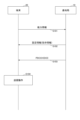
- FIG. 3 is a diagram illustrating a basic operation example of the embodiment.
- FIG. 7 is a diagram for explaining a third embodiment.
- FIG. 7 is a diagram for explaining a fourth embodiment.
- FIG. 7 is a diagram for explaining a fourth embodiment.
- FIG. 7 is a diagram for explaining a fourth embodiment.
- FIG. 7 is a diagram for explaining a fourth embodiment.
- FIG. 7 is a diagram for explaining a fourth embodiment.
- FIG. 7 is a diagram for explaining a fourth embodiment.
- FIG. 7 is a diagram for explaining a fourth embodiment.
- FIG. 7 is a diagram for explaining a fourth embodiment.
- FIG. 7 is a diagram for explaining a fourth embodiment.
- FIG. 7 is a diagram for explaining a fourth embodiment.
- FIG. 7 is a diagram for explaining a fourth embodiment.
- FIG. 7 is a diagram for explaining a fourth
- FIG. 7 is a diagram for explaining a fourth embodiment.
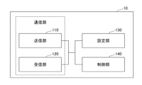
- 1 is a diagram showing a configuration example of a base station 10.
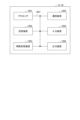
- FIG. 2 is a diagram showing an example of the configuration of a terminal 20.
- FIG. 1 is a diagram showing an example of the hardware configuration of a base station 10 or a terminal 20 in an embodiment of the present invention.
- FIG. 1 is a diagram showing an example of the configuration of a vehicle.
- Existing technologies are used as appropriate for the operation of the wireless communication system according to the embodiment of the present invention.
- the existing technology is, for example, existing LTE or existing NR, but is not limited to existing LTE or NR.
- SS Synchronization signal
- PSS Primary SS
- SSS Secondary SS
- PBCH Physical broadcast channel
- PRACH Physical broadcast channel
- PDCCH Physical Downlink Control Channel
- PDSCH Physical Downlink Shared Channel
- PUCCH Physical Uplink Control Channel
- PUSCH Physical Uplink Shared Channel
- NR corresponds to NR-SS, NR-PSS, NR-SSS, NR-PBCH, NR-PRACH, etc.
- NR- the signal is used for NR, it is not necessarily specified as "NR-".
- the duplex method may be a TDD (Time Division Duplex) method, an FDD (Frequency Division Duplex) method, or other methods (for example, Flexible Duplex, etc.). ) may be used.
- configure the wireless parameters etc. may mean pre-configuring a predetermined value, or may mean that the base station 10 or Wireless parameters notified from the terminal 20 may be set.
- FIG. 1 is a diagram showing a configuration example (1) of a wireless communication system according to an embodiment of the present invention.
- a wireless communication system according to an embodiment of the present invention includes a base station 10 and a terminal 20, as shown in FIG. Although FIG. 1 shows one base station 10 and one terminal 20, this is just an example, and there may be a plurality of each.
- the base station 10 is a communication device that provides one or more cells and performs wireless communication with the terminal 20.
- the physical resources of a radio signal are defined in the time domain and frequency domain, and the time domain may be defined by the number of OFDM (Orthogonal Frequency Division Multiplexing) symbols, and the frequency domain may be defined by the number of subcarriers or resource blocks. Good too.
- Base station 10 transmits a synchronization signal and system information to terminal 20.
- the synchronization signals are, for example, NR-PSS and NR-SSS.
- System information is transmitted, for example, on NR-PBCH, and is also referred to as broadcast information.
- the synchronization signal and system information may be called SSB (SS/PBCH block). As shown in FIG.
- the base station 10 transmits a control signal or data to the terminal 20 on the DL (Downlink), and receives the control signal or data from the terminal 20 on the UL (Uplink). Both the base station 10 and the terminal 20 can perform beamforming to transmit and receive signals. Furthermore, both the base station 10 and the terminal 20 can apply MIMO (Multiple Input Multiple Output) communication to DL or UL. Further, both the base station 10 and the terminal 20 may communicate via a secondary cell (SCell) and a primary cell (PCell) using CA (Carrier Aggregation). Furthermore, the terminal 20 may communicate via a primary cell of the base station 10 and a primary SCG cell (PSCell) of another base station 10 using DC (Dual Connectivity).
- SCell secondary cell
- PCell primary cell
- DC Direct Connectivity
- the terminal 20 is a communication device equipped with a wireless communication function, such as a smartphone, a mobile phone, a tablet, a wearable terminal, or a communication module for M2M (Machine-to-Machine). As shown in FIG. 1, the terminal 20 receives control signals or data from the base station 10 in the DL, and transmits control signals or data to the base station 10 in the UL to receive various signals provided by the wireless communication system. Use communication services. Furthermore, the terminal 20 receives various reference signals transmitted from the base station 10, and measures the channel quality based on the reception results of the reference signals.
- M2M Machine-to-Machine
- the terminal 20 is capable of performing carrier aggregation, which bundles multiple cells (multiple CCs (Component Carriers)) and communicates with the base station 10.
- carrier aggregation one PCell (Primary Cell) and one or more SCell (Secondary Cell) are used.
- PCell Primary Cell
- SCell Secondary Cell
- PUCCH-SCell having PUCCH may be used.
- FIG. 2 is a diagram for explaining an example (2) of a wireless communication system according to an embodiment of the present invention.
- FIG. 2 shows a configuration example of a wireless communication system when DC (Dual Connectivity) is executed.
- a base station 10A serving as an MN (Master Node) and a base station 10B serving as an SN (Secondary Node) are provided.
- Base station 10A and base station 10B are each connected to the core network.
- Terminal 20 can communicate with both base station 10A and base station 10B.
- the cell group provided by the base station 10A, which is an MN, is called an MCG (Master Cell Group), and the cell group provided by the base station 10B, which is an SN, is called an SCG (Secondary Cell Group).
- an MCG is composed of one PCell and one or more SCells
- an SCG is composed of one PSCell (Primary SCG Cell) and one or more SCells.
- the processing operations in this embodiment may be executed with the system configuration shown in FIG. 1, may be executed with the system configuration shown in FIG. 2, or may be executed with a system configuration other than these.
- the terminal 20 does not support the UL Tx switching function (uplink transmission switching function), which is a function that can switch UL transmission between 2 bands (2 carriers). There is. Even if the terminal 20 has only two transmission chains (Tx Chain), by using the UL Tx switching function, it is possible to transmit using two antenna ports on one carrier, or use one antenna port on one carrier. Operations such as transmitting to another carrier using another antenna port can be performed by switching over time.
- UL Tx switching function uplink transmission switching function
- the transmission chain is a physical function for transmission in the terminal 20, regardless of whether actual transmission is performed or not.
- One transmission chain can perform transmission on one carrier.
- the carrier transmission function unit corresponding to the carrier
- the antenna port is an antenna that can actually perform transmission using a transmission chain (Tx Chain).
- Tx Chain transmission chain
- antenna port are sometimes used interchangeably.
- the "antenna port” may also be referred to as a "port.”
- one band has one carrier. Therefore, in this specification and claims, “band” may be replaced with “carrier”, and “carrier” may be replaced with “band”.
- one band having one carrier is just an example, and one band may have multiple carriers. When there are multiple carriers in one band, their number and relationship may be limited, for example, up to two carriers that are consecutive in frequency. Multiple carriers within one band may be treated similarly to one UL band (carrier) in the following description.
- the above function sets 3 or 4 UL bands (carriers) for terminals that cannot perform UL CA (Carrier Aggregation), or can only do up to 2 UL CAs, and dynamically selects one of them.
- This function allows the base station 10 to instruct transmission on one or two UL bands (carriers).
- the terminal 20 that supports UL CA is configured with multiple DL/UL carriers as serving cells, with the number of UL CA CCs supported by the terminal 20 being less than or equal to the number of UL CA CCs supported by the terminal 20, and the UL CC used for transmission is dynamically configured among them. can be given instructions.
- Rel-18 UL Tx switching it is necessary to set a greater number of UL carriers than the number of UL CA CCs supported by UL CA.
- SUL supplemental uplink
- NUL normal uplink
- dynamic switching but it is not intended to extend the SUL framework.
- Rel-16 and Rel-17 the UL Tx switching of Rel-16 and Rel-17, power boosting, switching period, DL interruption, etc., and the operation of these themselves.
- Re l-18 UL Tx switching is basically the same as Rel-16 and Rel-17.
- Rel-16 (UL Tx switching for Rel-16)
- the terminal 20 supports two carriers and has two transmission chains.
- One transmission chain is fixed to one carrier, but the other transmission chain can be associated with either of the two carriers by a switch. Therefore, for example, it is possible to perform simultaneous transmission using two antenna ports with one carrier. It is also possible for each antenna port to perform transmission using one carrier and one antenna port. These methods can be dynamically switched.
- Rel-16 UL Tx switching is called Rel-16 1Tx-2Tx switching.
- case 1 a configuration in which each transmission chain is associated with one carrier
- case 2 a configuration in which two transmission chains are associated with one carrier
- Figure 4 shows the configuration of the transmission chain used for transmission in case 1 and case 2 in SUL.
- case 1, 1T+1T means that carrier 2 is connected to transmission chain 1 and carrier 1 is connected to transmission chain 2 in the example of FIG.
- 1P+0P in the 1T+1T state means that antenna port 2 performs transmission using carrier 1, but antenna port 1 does not perform transmission.
- SUL two carriers cannot be set at the same time, so 1P+1P does not exist.
- SUL does not assume the transmission of only NUL (carrier 2), so 0P+1P does not exist.
- 0P+2P, 0P+1P in case 2 means that antenna port 1 and antenna port 2 transmit using carrier 2, or antenna port 1 only transmits using carrier 2.
- Rel-16 1Tx-2Tx switching in inter-band CA/EN-DC has option 1, which does not allow the use of two carriers at the same time, and option 2, which allows the use of two carriers at the same time.
- the transmission chain configuration used for transmission in option 1 is the same as that shown in FIG.
- the transmission chain configuration used for transmission in option 2 is as shown in FIG.
- FIG. 6 shows an example of UE Capability reported from the terminal 20 to the base station 10, which is defined in response to Rel-16 1Tx-2Tx switching.
- FIG. 7 shows an example of CellGroupConfig and ServingCellConfig that are defined in response to Rel-16 1Tx-2 Tx switching and are set from the base station 10 to the terminal 20.
- uplinkTxSwitchingPeriodLocation-r16 in ServingCellConfig indicates whether UL Tx switching period is set in the target cell (carrier). Examples of operations related to the UL Tx switching period are shown in Figures 8 and 9.
- FIG. 8 is an example of a case where it is set that a UL Tx switching period occurs in carrier 1.
- a UL Tx switching period occurs in carrier 1 both when switching from carrier 1 to carrier 2 and when switching from carrier 2 to carrier 1.
- FIG. 9 is an example of a case where it is set that a UL Tx switching period occurs in carrier 2.
- the terminal 20 When dynamically switching between two carriers, the terminal 20 is allowed to have a predetermined length of DL communication interruption (DL interruption) in the DL carrier overlapping the UL switching period. . Its length (X OFDM symbols) is defined as shown in FIG.
- a summary of Rel-16 UL Tx switching is as follows. Based on the PUSCH scheduling (scheduling command, rank adaptation) from the base station 10, the terminal 20 performs "1 port transmission on carrier 1", “1 port transmission on carrier 2", "1 port transmission on carrier 1 + Can dynamically switch between 1-port transmission on carrier 2 (applicable only if inter-band CA supports option 2) and 2-port transmission on carrier 2 (with or without 3dB power boosting) It is.
- a switching period occurs when the carrier connected to the transmission port switches, and during the switching period, UL transmission is not performed on either carrier. There are also cases where DL interruption occurs during the Switching period.
- each of the two transmission chains can support two carriers, resulting in 2Tx-2Tx UL Tx switching. Since 2-port transmission is possible even with carrier 1, in addition to case 1 and case 2, case 3 is compared to Rel-16 as a case of the transmission chain and carrier connection pattern, as shown in Figure 11. will be added. Therefore, for the terminal 20 and the base station 10, it is necessary to distinguish between Rel-17 (2Tx-2Tx UL Tx switching) and Rel-16 (1Tx-2Tx).
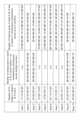
- FIG. 12 shows patterns of the number of transmission ports for each case and each option (whether or not simultaneous transmission is possible with two carriers).
- FIG 13 shows an example of RRC settings in Rel-17.
- uplinkTxSwitching-2T-Mode-r17 indicates the setting to be in the 2Tx-2Tx UL Tx switching mode
- uplinkTxSwitching-DualUL-TxState-r17 indicates which case should be switched to during switching, as described above. This is information for setting which case to switch to when there are multiple candidates for the case.
- the number of bands is two, as shown in Figure 14, but it is supported to use two consecutive carriers in one of the bands. Examples of configurations of transmission ports in each case in the example of FIG. 14 are shown in FIGS. 15 and 16.
- Rel-16 and Rel-17 explained above may be applied to Rel-18 UL Tx switching.
- UL Tx switching schemes across up to 3 or 4 bands with restriction of up to 2 Tx simultaneous transmission is assumed, but this is just an example.
- the maximum number of bands within which transmission switching is performed may be greater than four.
- the number of antenna ports used for transmission may be greater than two. In other words, there may be cases where simultaneous transmission occurs at three or more antenna ports.
- This embodiment includes a first embodiment and a second embodiment. A basic operation example common to the first embodiment and the second embodiment will be described with reference to FIG. 19.
- the terminal 20 transmits capability information (Capability) to the base station 10.
- Capability capability information
- the base station 10 transmits configuration information (or instruction information) to the terminal 20. Examples of setting information/instruction information will be explained in the second embodiment.
- the base station 10 determines the settings/instructions for the terminal 20 within the capability of the terminal 20 indicated in the capability information of the terminal 20 received in S101, creates setting information/instruction information, and sends the instructions in S102. Send.
- such an assumption is just an example.
- the terminal 20 that received the setting information/instruction information in S102 operates according to the information.
- the terminal 20 when the terminal 20 receives the DCI from the base station 10, it switches the band to which the port is connected based on the DCI according to the setting information, and performs transmission using the switched port in S104.
- the configuration information/instruction information in S102 may be transmitted using any of RRC signaling, MAC CE, and DCI.
- RRC signaling any of RRC signaling, MAC CE, and DCI.
- the terminal 20 reports at least one of the plurality of capability information listed below to the base station 10 as a capability that it supports for Rel-18 UL Tx switching. All of the examples listed below are examples of capability information regarding bands.
- Terminal 20 receives at least one of the plurality of configuration information/instruction information listed below from base station 10 as configuration information/instruction information for Rel-18 UL Tx switching. In other words, the base station 10 transmits to the terminal 20 at least one of the plurality of configuration information/instruction information listed below. All of the examples listed below are examples of information regarding band switching.
- ⁇ DL/UL serving cell and UL only serving cell (or either DL/UL serving cell or UL only serving cell) including UL used for Rel-18 UL Tx switching -
- Other serving cells for which switching and/or simultaneous transmission can be instructed in each serving cell ⁇ For each serving cell, for each combination with other serving cells ⁇ whether or not to include a switching period, whether power boosting is allowed, whether simultaneous transmission is allowed, and whether to switch from a specific port configuration to another specific port configuration. Case interpretation when switching is instructed ⁇ - Number of ports subject to band switching - Whether each serving cell is linked to a port subject to band switching (or not subject to band switching)
- Examples 1 to 9 of the first embodiment can be implemented in combination with any of Examples 1 to 9 of the second embodiment, respectively.
- the terminal 20 reports at least one of the capability information shown in Examples 1 to 9 below to the base station. Additionally, information that combines any or all of Examples 1 to 9 may be reported.
- the terminal 20 reports information regarding one or more band combinations (BC) for UL Tx switching supported for Rel-18 UL Tx switching to the base station 10, separately from the BC for UL CA.
- BC band combinations
- the band combination (BC) for UL Tx switching to be reported may include BCs that are not compatible with UL CA.
- Each BC included in one or more band combinations (BC) for UL Tx switching may be information indicating a combination of bands to be switched.
- the terminal 20 when the terminal 20 reports BC1, BC2, and BC3 as the BC for UL CA, the terminal 20 may report BC4 and BC5 as the band combination (BC) for UL Tx switching.
- BC1 BC2, and BC3
- BC4 and BC5 as the band combination (BC) for UL Tx switching.
- each BC included in one or more band combinations (BC) for UL Tx switching to be reported must be a UL CA compatible BC.
- Rel-18 has the restriction that when reporting a BC for UL Tx switching, it must support each "band combination" within the BC. good. In this case, for example, when reporting BC of Band A-B-C in Rel-18, it is necessary to also support A-B, A-C, and B-C.
- Terminal 20 reports information regarding the number of CCs supported in each band of BC for UL Tx switching described in Example 1 to base station 10.
- the information regarding the number of CCs may be the number of CCs (the number of cells) itself.
- the band in Example 2 (the band for reporting the number of CCs) may be a band other than the band within the BC reported in Example 1.
- the upper limit of the number of CCs or the total bandwidth that can be supported in each band in Rel-18 UL Tx switching may be specified in the specifications.
- the number of CCs that the terminal 20 can support may be defined as "up to 2 consecutive CCs" or "consecutive CCs within the 100 MHz band.”
- the upper limit of the number of CCs that can be supported or the total bandwidth may be defined not for each band but for each of TDD and FDD.
- base station 10 configures CC within the band for UL Tx switching for terminal 20 according to these regulations.
- Example 3 For each band of BC for UL Tx switching described in Example 1, the terminal 20 reports information regarding whether or not a DL carrier associated with that band is necessary to the base station 10. For example, if a certain BC has Band_A, Band_B, and Band_C, then for that BC, ⁇ Band_A: DL carrier required, Band_B: DL carrier not required, Band_C: DL carrier not required , ⁇ . Note that since the terminal 20 basically only needs to be able to perform DL reception on any carrier, a DL carrier may not be necessary in a certain band.
- the specifications may specify conditions for a UL carrier/band that does not require a linked DL carrier. Conditions include, for example, TDD (or FDD), a specific band, and only when a specific band is included in BC.
- TDD or FDD
- the band in Example 3 (the band that reports the necessity of DL carrier) may be a band other than the band within the BC reported in Example 1.
- Example 4 The terminal 20 reports to the base station 10 information regarding the presence or absence of simultaneous transmission support for each combination of bands to be switched within the BC for UL Tx switching described in Example 1.
- the terminal 20 reports to the base station 10 information such as that in the BC of bands A-B-C-D, simultaneous transmission is possible for bands A-B (dual UL or both), and simultaneous transmission is not possible for A-C and A-D (switched UL).
- the terminal 20 requests the base station 10 not for each combination of bands to be switched, but for each band, or for any combination within a BC, or for all Rel-18 UL Tx switching BCs that the terminal 20 supports. Information regarding the presence or absence of simultaneous transmission support may be reported to the sender.
- the band in Example 4 (the band for which the presence or absence of simultaneous transmission support is reported) may be a band other than the band within the BC reported in Example 1.
- the terminal 20 reports information regarding the switching period for each combination of bands to be switched within the BC for UL Tx switching described in Example 1.
- the information regarding the switching period may be the value of the switching period.
- the terminal 20 reports information to the base station 10 that in BC of bands A-B-C-D, the switching period of band A-B is n35 ⁇ s, and the switching period of A-C and A-D is n140 ⁇ s.
- the terminal 20 requests the base station 10 not for each combination of bands to be switched, but for each band, or for any combination of the above BCs, or for all Rel-18 UL Tx switching BCs supported by the terminal. may report information regarding the switching period.
- new switching period candidate values may be defined for Rel-18 UL Tx switching, and some values that could be reported for Rel-16/17 cannot be reported for Rel-18. You can also use it as
- the band in Example 5 (the band reporting the switching period) may be a band other than the band in BC reported in Example 1.
- the terminal 20 may report the band in which the DL interruption occurs for each combination of bands to be switched in the BC for UL Tx switching described in Example 1.
- the terminal 20 reports 0100 for bands A-B, 1010 for A-C, etc. in BC of bands A-B-C-D to the base station 10.
- This bitmap shows bands A-B-C-D, meaning that DL interruption occurs during switching in the band corresponding to the 1 bit.
- the terminal 20 requests the base station 10 not for each combination of bands to be switched, but for each band, or for any combination of the above BCs, or for all Rel-18 UL Tx switching BCs supported by the terminal. may report information about the band in which the DL interruption occurs.
- the specifications may specify whether DL interruption is allowed for each band combination for Rel-18 UL Tx switching or for each combination of two bands within a band combination.
- the band in Example 6 may be a band other than the band within the BC reported in Example 1.
- the base station 10 that has received information indicating that DL interruption will occur in a certain band may, for example, perform scheduling assuming that DL interruption will occur when scheduling DL reception in that band. good.
- the terminal 20 may report information regarding whether or not power boosting is supported for each combination of bands to be switched within the BC for UL Tx switching described in Example 1.
- the terminal 20 reports information to the base station 10, such as that power boosting is possible in bands A-B and power boosting is not possible in bands A-B-C-D in BC of bands A-B-C-D.
- power boosting is possible in bands A-B. power
- being capable of power boosting in bands A-B may mean being able to increase transmission power (output power) when simultaneously transmitting bands A and B.
- the terminal 20 requests the base station 10 not for each combination of bands to be switched, but for each band, or for any combination within a BC, or for all BCs for Rel-18 UL Tx switching that the terminal supports. You may also report information regarding whether power boosting is supported.
- the band in Example 7 (the band that reports power boosting availability) may be a band other than the band in BC reported in Example 1.
- the base station 10 When the base station 10 receives information indicating that power boosting is possible in a certain band, it uses DCI or MAC CE to perform power boosting when scheduling 2-port simultaneous transmission in that band. Transmission power control may be performed on the terminal 20 according to the following.
- the terminal 20 may report to the base station 10 information regarding the number of ports (eg, 1 or 2) capable of band switching within the BC for UL Tx switching described in Example 1. Furthermore, if there is a port to which the band is fixed, the target band of the port to which the band is fixed may be reported. For example, the terminal 20 reports information such as that port 1 is fixed to band A in BC of band ABCD to the base station 10.
- the number of ports eg, 1 or 2
- the target band of the port to which the band is fixed may be reported. For example, the terminal 20 reports information such as that port 1 is fixed to band A in BC of band ABCD to the base station 10.
- a predetermined number of layers for example, 2 as the number of MIMO layers for that target band, and report a predetermined number of layers as the number of MIMO layers for other bands.
- the number of layers for example, 2) may not be reported.
- the band in Example 8 (the target band for which the number of ports capable of band switching is reported) may be a band other than the band within the BC reported in Example 1.
- the terminal 20 may report information regarding switching candidate bands at each port within the BC for UL Tx switching described in Example 1. For example, the terminal 20 reports information to the base station 10 such as that A and B are switching candidates for port 1 and A, B, C, and D are switching candidates for port 2 in BC of band ABCD. do.
- the terminal 20 may report to the base station 10 the number of supported ports in each band within the BC (eg, A is 2, B is 2, C is 1, D is 1, etc.).
- the band (switching candidate band) in Example 9 may be a band other than the band within the BC reported in Example 1.
- the base station 10 can know the capability related to UL Tx switching of the terminal 20, so it can appropriately perform UL Tx switching. It becomes possible to carry out settings, instructions, or scheduling for.
- the terminal 20 configures or configures at least one of the following examples 1 to 9 from the base station 10 using one or a combination of RRC signaling, MAC CE, and DCI. be instructed. Further, a combination of any plurality or all of Examples 1 to 9 may be set or instructed from the base station 10 to the terminal 20.
- the terminal 20 receives from the base station 10 a DL/UL serving cell (a cell having a UL carrier and a DL carrier) that includes UL used for Rel-18 UL Tx switching, or a UL that includes UL used for Rel-18 UL Tx switching. Only serving cell (UL carrier only cell) is set. Even if the terminal 20 is set by the base station 10 as both a DL/UL serving cell that includes UL used for Rel-18 UL Tx switching and a UL only serving cell that includes UL used for Rel-18 UL Tx switching. good.
- “certain information is set” means that the terminal 20 receives the information from the base station 10.
- the base station 10 can determine which cell to set for the terminal 20 based on the Capability received from the terminal 20 in the first embodiment. For example, the base station 10 can set the cell (carrier) included in the BC received in Example 1 of the first embodiment as the serving cell in the terminal 20.
- the base station 10 may set a cell in a band that does not require a DL carrier as a UL only serving cell in the terminal 20 based on the information received in Example 3 of the first embodiment.
- the serving cell in Examples 2 to 9 below is the cell set in the terminal 20 in Example 1.
- the present invention is not limited to this, and the serving cell in Examples 2 to 9 below may be a cell other than the cell set in Example 1.
- the following settings/instructions in Examples 2 to 9 may be performed at the time of cell setting in Example 1, or may be performed at a timing after cell setting in Example 1.
- Example 2 When the terminal 20 receives a specific IE/parameter from the base station 10 by ServingCellConfig for a certain cell, the specific IE/parameter is set in the terminal 20.
- the terminal 20 may recognize from the specific IE/parameter received from the base station 10 that the cell includes UL used for Rel-18 UL Tx switching.
- ServingCellConfig is an example, and other messages or signals may be used.
- the terminal 20 may recognize that the cell is a UL only serving cell used for Rel-18 UL Tx switching by having a specific IE/parameter set by the ServingCellConfig for a certain cell from the base station 10. .
- the terminal 20 recognizes from the base station 10 that the cell is a UL only serving cell used for Rel-18 UL Tx switching because a specific IE/parameter is not set in the ServingCellConfig for that cell, good.
- ServingCellConfig is an example, and other messages or signals may be used.
- the terminal 20 is configured with information regarding other serving cells for which switching and/or simultaneous transmission can be instructed in each serving cell from the base station 10. For example, assume that ServingCellConfig includes information on other serving cells for which switching/simultaneous transmission can be instructed.
- the terminal 20 receives an RRC message for cell A (e.g. ServingCellConfig) and detects that cell B exists in the RRC message as another serving cell for which switching/simultaneous transmission can be instructed, cell A Assume that switching/simultaneous transmission with cell B and cell B can be instructed.
- RRC message for cell A e.g. ServingCellConfig
- the terminal 20 may be set with information from the base station 10 regarding whether each serving cell includes a switching period for each combination with another serving cell. Alternatively, information regarding whether a switching period is included may be set for each serving cell or for each cell group, rather than for each combination with other serving cells.
- a certain RRC message (eg ServingCellConfig, CellGroupConfig) includes information regarding whether or not a switching period is included.
- RRC message eg ServingCellConfig, CellGroupConfig
- terminal 20 receives an RRC message for cell A and detects information in the RRC message that means that "a switching period exists in cell B when switching between cell A and cell B.” .
- the terminal 20 receives UL scheduling information that causes switching between cell A and cell B, it performs switching in the switching period on the cell B side.
- a certain RRC message e.g. ServingCellConfig, CellGroupConfig
- the terminal 20 receives the RRC message, and the RRC message includes a message that states, "When switching between cell A and cell B, power boosting may be performed when two ports transmit simultaneously in cell A.”
- the terminal 20 performs power boosting when receiving UL scheduling information that causes simultaneous two-port transmission in cell A due to switching from cell B to cell A, for example.
- the terminal 20 is set with information from the base station 10 regarding whether or not each serving cell may perform simultaneous transmission for each combination with other serving cells. Alternatively, information regarding whether simultaneous transmission may be performed per serving cell or per cell group may be set, rather than per combination with other serving cells.
- information regarding whether simultaneous transmission may be performed per serving cell or per cell group may be set, rather than per combination with other serving cells.
- the settings for each serving cell for example, if "simultaneous transmission OK" is set in the settings for cell A, it means that simultaneous transmission is OK with any cell as long as it is combined with cell A. It can mean something.
- a certain RRC message e.g. ServingCellConfig, CellGroupConfig
- a certain RRC message contains information regarding whether simultaneous transmission is allowed.
- the terminal 20 receives an RRC message for cell A and detects in the RRC message information indicating that "simultaneous transmission is possible in cell A and cell B."
- the terminal 20 receives UL scheduling information that is simultaneously transmitted in cell A and cell B.
- base station 10 can perform UL scheduling for terminal 20 that causes simultaneous transmission in cell A and cell B.
- the terminal 20 is set with information regarding case interpretation when each serving cell is instructed by the base station 10 to switch from a specific port configuration to another specific port configuration for each combination with other serving cells. Good too. Alternatively, information regarding case interpretation may be set when switching from a specific port configuration to another specific port configuration is instructed not for each combination with other serving cells but for each serving cell or cell group. .
- a certain RRC message e.g. ServingCellConfig, CellGroupConfig
- a certain RRC message contains information regarding case interpretation.
- the terminal 20 receives the above RRC message, and in the RRC message there is a message that states, ⁇ From a certain Tx chain state (a certain case number) to another Tx chain state (another case number) after UL Tx switching. ), if the case number of the transition destination is not uniquely determined, if it is detected that it contains "information for uniquely determining the transition destination case number", the UL Tx Determine the transition destination Tx chain (port configuration) after switching.
- the above “information for determining” may be an explicit “pair of case number before transition and case number of transition destination", or it may indicate that "two ports are connected to one carrier" It may be information or information indicating that "one port is connected to one carrier”.
- the terminal 20 is set as the above explicit information such that "If the terminal is in case 2 before the transition and there are cases 1 and 3 as candidates for transition, transition to case 3." At this time, in case 2, the terminal 20 switches to case 3 if scheduling corresponding to 1P+0P+0P+0P is performed by the DCI.
- the base station 10 can perform subsequent scheduling assuming the above transition destination.
- the terminal 20 is set with information regarding the number of ports subject to band switching for each cell group from the base station 10. In addition to this, or instead of this, the terminal 20 may be set with information from the base station 10 regarding whether each serving cell is associated with a port to which band switching is to be performed. Furthermore, the terminal 20 may be set with information from the base station 10 regarding whether each serving cell is associated with a port that is not subject to band switching.
- the information regarding whether or not the serving cell is linked to the port to which the band is to be switched is an example of the information regarding the antenna port to which the band is to be switched.
- Information regarding whether serving cell is linked to a port not subject to band switching is an example of information regarding an antenna port not subject to band switching.
- the terminal 20 receives information corresponding to "Cell A and cell B are subject to port 1 switching, and cell C permanently uses port 2" from the base station 10 via an RRC message. Then, it is assumed that scheduling is performed corresponding to "transmission is performed in cell A or cell B using port 1, and transmission is performed in port 2 in cell C". Furthermore, the base station 10 can perform scheduling for the terminal 20 that corresponds to "transmitting in cell A or cell B using port 1, and transmitting in cell C using port 2.”
- the base station 10 can perform settings/instructions to the terminal 20 according to the capability related to UL Tx switching. It becomes possible to appropriately implement switching.
- Alt.1 is a method of dynamically switching bands between 3 or 4 bands based on UL scheduling (DCI).
- DCI UL scheduling
- Alt.2 notifies 2 of 3 or 4 bands by MAC CE or DCI from the NW, and then uses UL scheduling (DCI) between the notified 2 bands, similar to Rel-17. This method dynamically switches bands.
- Alt.3 sets one band out of 3 or 4 bands as the anchor band, and dynamically switches the band based on UL scheduling (DCI) only between the anchor band and non-anchor band. This is an acceptable method. That is, Alt.3 does not allow dynamic band switching between non-anchor bands.
- DCI UL scheduling
- the number of bands used for UL transmission is 3 or 4
- the number of switching cases that is, the number of states that are candidates for switching
- the number of switching cases is 10.
- uplink transmission (UL transmission) is performed using N bands (N is a natural number equal to or less than M), which are selected from M (M is a natural number equal to or greater than 3) bands.
- M may be 3 or 4 similarly to Rel-18. However, M may be 5 or more.
- N may be 1 or 2 as in Rel-18. However, N may be 3 or more.
- UL transmission may be read as PUSCH transmission.
- a band is reserved for switching the band used for UL transmission from one or more first bands (hereinafter referred to as 1st band(s)) to one or more second bands (hereinafter referred to as 2nd band(s)).
- the specific time may be referred to as a minimum scheduling offset.
- 1 st band(s) may be referred to as 1 st Tx chain(s) or 1 st BC (Band Combination)
- 2 nd band(s) may be referred to as 2 nd Tx chain(s) or 2 nd BC. may be called.
- Alt.1 described above is adopted.
- the Minimum scheduling offset may be counted by a specific timer.
- the minimum scheduling offset may be expressed by a number (eg, X symbols) of unit time (eg, symbols).
- the minimum scheduling offset may be expressed in absolute time (eg, ⁇ sec).
- the subcarrier spacing used to determine the symbol length may be specified. For example, the symbol length may always be determined based on a specific subcarrier spacing, or UL Tx switching The symbol length may be determined based on either or both of the subcarrier intervals used in the switching source band and switching destination band.
- the start timing of the Minimum scheduling offset (that is, the activation timing of a specific timer) may be the reception timing of the DCI that schedules UL transmission using the 2nd band(s), for example, the timing of receiving the PDCCH resource including the DCI.
- the timing may be the end timing or the timing when a predetermined processing time has elapsed from the end timing of the PDCCH resource.
- the start timing of the Minimum scheduling offset may be the later of the DCI reception timing described above and the timing at which PUSCH transmission in the switching source band is completed.
- the reception timing of the DCI may be the last symbol in which the DCI is received, or the last symbol of the slot in which the DCI is received.
- the end timing of the PDCCH resource may be the last symbol in which the PDCCH is received, or may be the last symbol in the slot in which the PDCCH is received. Also, if the end timing of the Minimum scheduling offset is the start timing of UL transmission using 2nd band(s) (e.g. PUSCH) or Switching for UL transmission using 2nd band(s) (e.g. PUSCH), It may be specified that it is not assumed that the timing will be later than the start timing of the period, or it may be specified that UL transmission is not assumed to be performed in such a case.
- the start timing of UL transmission may be the first symbol scheduled for UL transmission, or may be the first symbol of a slot scheduled for UL transmission.
- Bands A, B, and C are set as bands that can be used for UL transmission
- UL Tx Switching from Bands A, B ( 1st bands) to Bands B, C ( 2nd bands) An example is given below.
- the minimum scheduling offset is secured between the DCI C reception timing or the end of PUSCH transmission in the switching source band and the start timing of Band C PUSCH or the start timing of the switching period for that purpose. It may be considered that the minimum time required for In other words, when receiving DCI C, the terminal 20 does not expect to transmit a Band C PUSCH before the Minimum scheduling offset has elapsed, but instead assumes to transmit a Band C PUSCH after the Minimum scheduling offset has elapsed. do. In other words, when receiving DCI C, the terminal 20 does not assume scheduling of PUSCH transmission in Band C for the timing before the Minimum scheduling offset has elapsed, but at the timing after the Minimum scheduling offset has elapsed. Assume scheduling of PUSCH transmission in Band C.
- the UL Tx switching period (switching period in FIG. 20) may be included in Band A or Band C, as explained in FIGS. 8 and 9.
- Minimum scheduling offset may be considered a concept that includes UL Tx switching period.
- the Minimum scheduling offset is set taking into consideration the UL Tx switching period, and a case where it is larger than the UL Tx switching period may be assumed. In such a case, the terminal 20 may assume that the Band C PUSCH is transmitted after the Minimum scheduling offset has elapsed.
- Minimum scheduling offset may be considered a concept that does not include UL Tx switching period.
- the Minimum scheduling offset may be set without considering the UL Tx switching period.
- Minimum scheduling offset and UL Tx switching period may include overlapping times. It may be specified that the start timing of the UL Tx switching period is assumed to be after the expiration timing of the Minimum scheduling offset.
- the terminal 20 may expect to transmit the Band C PUSCH after the later of either the Minimum scheduling offset or the UL Tx switching period has elapsed.
- the base station 10 may assume scheduling such that the Band C PUSCH is transmitted after the later of either the Minimum scheduling offset or the UL Tx switching period has elapsed.
- Example 1 In example 1, the terminal 20 reports capability information (UE Capability) regarding Minimum scheduling offset to the base station 10 (NW). The following options are possible for UE Capability.
- UE Capability capability information regarding Minimum scheduling offset to the base station 10 (NW).
- NW base station 10
- the UE Capability may include an information element (hereinafter referred to as the first information element) indicating whether Minimum scheduling offset is required.
- the UE Capability may include an information element (hereinafter referred to as a second information element) indicating the value of Minimum scheduling offset.
- the first information element or the second information element is commonly reported for the entire band that can be used for UL transmission (M bands), i.e., the band combination that configures UL Tx switching. may be done.
- the first information element or the second information element may be reported every 1 st band(s) before UL Tx Switching, and some bands included in the 1 st band(s) ( may be reported for each serving cell).
- the 1st band(s) or some bands included in the 1st band(s) are an example of one or more specific bands.
- the first information element or the second information element may be reported for every 2nd band(s) after UL Tx Switching, and some bands included in the 2nd band(s) ( may be reported for each serving cell).
- the 2nd band(s) or some bands included in the 2nd band(s) are an example of one or more specific bands.
- the first information element or the second information element may be reported for each combination of 1st band(s) and 2nd band(s) and is included in 1st band(s). It may be reported for each combination of some bands (serving cells) and some bands (serving cells) included in the 2nd band(s).
- a combination is an example of one or more specific bands.
- the first information element or the second information element may be reported separately depending on whether simultaneous transmission is allowed on multiple carriers. For example, if simultaneous transmission is not allowed on multiple carriers, the first information element may be an information element indicating that Minimum scheduling offset is not required, and the second information element may be an information element indicating that the value of Minimum scheduling offset is It may be an information element that indicates zero or an information element that indicates a smaller value than when simultaneous transmission is allowed on multiple carriers. If simultaneous transmission is allowed on multiple carriers, the first information element may be an information element indicating that a Minimum scheduling offset is required, and the second information element may be an information element indicating that a Minimum scheduling offset (zero) is required. The information element may also be an information element that indicates a value larger than that of a case where simultaneous transmission is not permitted on multiple carriers.
- Option 1 may be referred to as switched UL.
- Option 2 simultaneous transmission across up to 2 carriers.
- Option 2 may be referred to as dual UL.
- the second information element may be different depending on whether the UL transmission involves UL Tx Switching or not.
- the value of Minimum scheduling offset corresponding to the case with UL Tx Switching may be larger than the value of Minimum scheduling offset corresponding to the case without UL Tx Switching.
- the value of Minimum scheduling offset for cases without UL Tx Switching may be zero. It may be considered that the Minimum scheduling offset does not apply in cases that do not involve UL Tx Switching.
- the second information element may be different depending on whether the 2nd band(s) is different from the 1st band(s).
- the value of Minimum scheduling offset corresponding to the case where 2nd band(s) is different from 1st band(s) is the value of Minimum scheduling offset corresponding to the case where 2nd band(s) is the same as 1st band(s). May be larger than the scheduling offset value.
- the second information element may be different depending on the number of Tx chains in which UL Tx Switching occurs.
- the number of Tx chains in which UL Tx Switching occurs may be considered to be the number of bands included in the 2nd band(s) that are different from the 1st band(s).
- the value of Minimum scheduling offset may be increased as the number of Tx chains in which UL Tx Switching occurs increases.
- the UE Capability may include information elements that are commonly defined for M bands. As explained in Options 1-4 to 1-6, UE Capability may include information elements that are individually defined for one or more specific bands included in the 1st band(s) and 2nd band(s). .
- the terminal 20 may control UL transmission assuming a specific time (Minimum scheduling offset).
- the value of the specific time may be a value reported by the UE Capability.
- the base station 10 may schedule UL transmission assuming a specific time (Minimum scheduling offset).
- the value of the specific time may be determined according to the value reported by the UE Capability.
- the value of Minimum scheduling offset may be set from base station 10 (NW) to terminal 20 by an RRC message, and may be notified from base station 10 (NW) to terminal 20 by MAC CE or DCI. .
- the following options are possible as the value of the Minimum scheduling offset to be set or notified.
- the value of Minimum scheduling offset may be set or notified according to the UE Capability.
- UE Capability may include information elements related to at least one of options 1-1 to 1-10.
- the value of Minimum scheduling offset that is set or notified may be greater than or equal to the value supported by the terminal 20.
- the value of Minimum scheduling offset may be set or notified in common across all bands (serving cells) that can be used for UL transmission, similar to option 1-3.
- the value of Minimum scheduling offset may be set or notified every 1st band(s) before UL Tx Switching, and is included in 1st band(s), similar to option 1-4. It may be set or notified for each serving cell.
- the 1st band(s) or some bands included in the 1st band(s) are an example of one or more specific bands.
- the value of Minimum scheduling offset may be set or notified for each 2nd band(s) after UL Tx Switching, similar to option 1-5. It may be set or notified for each serving cell.
- the 2nd band(s) or some bands included in the 2nd band(s) are an example of one or more specific bands.
- the value of Minimum scheduling offset may be set or notified for each combination of 1st band(s) and 2nd band(s), similar to option 1-6 . It may be set or notified for each combination of some bands (serving cells) included in (s) and some bands (serving cells) included in 2nd band (s). A combination is an example of one or more specific bands.
- the value of Minimum scheduling offset may be set or notified depending on whether simultaneous transmission is allowed on multiple carriers, similar to option 1-7.
- the value of Minimum scheduling offset may be set or notified depending on whether the UL transmission is accompanied by UL Tx Switching, similar to option 1-8.
- the value of Minimum scheduling offset may be set or notified depending on whether the 2 nd bands are different from the 1 st bands, similar to option 1-9.
- the value of Minimum scheduling offset may be set or notified according to the number of Tx chains in which UL Tx Switching occurs, similar to option 1-10.
- the terminal 20 may receive information that sets or notifies a specific time that is commonly determined for M bands.
- UE Capability is the ability to set or notify specific times that are individually determined for one or more specific bands included in 1st band(s) and 2nd band(s). You may also receive information that
- the terminal 20 may control UL transmission assuming a specific time (Minimum scheduling offset).
- the value of the specific time (Minimum scheduling offset) may be set or notified by the base station 10 (NW).
- the base station 10 may schedule UL transmission assuming a specific time (Minimum scheduling offset).
- the value of the specific time (Minimum scheduling offset) may be set or notified by the base station 10 (NW).
- the value of Minimum scheduling offset may be predefined in the wireless communication system.
- the value of Minimum scheduling offset may be defined in the same manner as one or more options selected from options 1-3 to 1-10 described above.
- the terminal 20 may control UL transmission assuming a specific time (Minimum scheduling offset).
- the value of the specific time (Minimum scheduling offset) may be predefined in the wireless communication system.
- the base station 10 may schedule UL transmission assuming a specific time (Minimum scheduling offset).
- the value of the specific time (Minimum scheduling offset) may be predefined in the wireless communication system.
- the specific time is the Minimum scheduling offset.
- the third embodiment is not limited to this.
- the specific time may have another name and may be defined as a time different from the Minimum scheduling offset.
- the specific time may be referred to as Switching preparation time.
- the Switching preparation time may be considered to be the time for rewriting information regarding the 1st band(s) to information regarding the 2nd band(s) in the memory.
- the Switching preparation time may be counted by a specific timer, similar to the Minimum scheduling offset.
- Switching preparation time may be expressed by a number (eg, X symbols) of unit time (eg, symbols).
- Switching preparation time may be expressed in absolute time (for example, ⁇ sec).
- the start timing of Switching preparation time (that is, the activation timing of a specific timer) may be the timing (first timing) when UL transmission of 1 st band(s) is completed, and the UL transmission of 1 st band(s) It may be at the beginning of the slot (second timing) immediately after the timing when the UL transmission is completed, or it may be at the reception timing (third timing) of the DCI that schedules UL transmission using the 2nd band(s).
- the timing may be a timing (fourth timing) when a certain processing time has elapsed from the third timing.
- the start timing of Switching preparation time is the timing related to UL transmission of 1st band(s) (first timing or second timing) and the timing related to DCI scheduling UL transmission using 2nd band(s) (third timing). or fourth timing), whichever is later.
- the timing at which UL transmission of 1st band(s) is completed is the timing at which UL transmission of the band to be rewritten is completed, which is a different band between 1st band(s) and 2nd band(s). It may be considered that However, the timing at which UL transmission of the 1st band(s) is completed may be considered to be the timing at which UL transmission of all bands included in the 1st band(s) is completed.
- Bands A, B, C, and D are set as bands that can be used for UL transmission
- UL transmission from Bands A, B ( 1st bands) to Bands C, D ( 2nd bands) An example of Tx Switching will be given.
- the Switching preparation time can be considered to be the minimum time that should be secured between the completion timing of PUSCH for Bands A and B and the start timing of PUSCH for Bands C and D.
- the start timing of PUSCH in Bands C, D may be the first symbol in which PUSCH is scheduled, or may be the first symbol in the slot in which PUSCH is scheduled. That is, the terminal 20 may not assume transmission of Band C, D PUSCH before Switching preparation time has elapsed, but may assume transmission of Band C, D PUSCH after Switching preparation time has elapsed. In other words, the terminal 20 may not assume the scheduling of Band C, D PUSCH before the Switching preparation time has elapsed, but may assume the scheduling of Band C, D PUSCH after the Switching preparation time has elapsed. .
- Switching preparation time may be considered to be a concept that includes UL Tx switching period, or may be considered to be a concept that does not include UL Tx switching period.
- Switching preparation time may be determined in the same way as the value of Minimum scheduling offset.
- Minimum scheduling offset may be replaced with Switching preparation time.
- the start timing of Minimum scheduling offset or Switching preparation time is the reception timing of MAC CE or DCI that notifies 2 bands from 3 or 4 bands, and PUSCH transmission to the newly notified band by MAC CE or DCI. It may be specified that the transmission timing of the DCI that issues the instruction is not assumed to be before the expiration timing of the Minimum scheduling offset or Switching preparation time. That is, the Minimum scheduling offset or Switching preparation time in the third embodiment may be read as above and applied to Alt.2.
- the band used in UL transmission is a band selected from M (M is a natural number of 3 or more) bands and uses N (N is a natural number of M or less) bands.
- a specific time (Minimum scheduling offset or Switching preparation time) is defined as the minimum time for switching from 1st band(s) to 2nd band(s).
- the terminal 20 reports UE Capability regarding a specific time (Minimum scheduling offset or Switching preparation time) to the base station 10 (NW). According to such a configuration, the specific time can be appropriately determined.
- the terminal 20 performs UL transmission assuming a specific time (Minimum scheduling offset or Switching preparation time).
- the base station 10 performs UL transmission scheduling assuming a specific time (Minimum scheduling offset or Switching preparation time). According to such a configuration, UL transmission can be appropriately performed.
- the terminal 20 secures the minimum scheduling offset and controls UL transmission when specific conditions are met.
- the base station 10 assumes UL reception with minimum scheduling offset when specific conditions are met.
- the terminal 20 controls UL transmission without ensuring the minimum scheduling offset.
- the base station 10 assumes UL reception without securing the minimum scheduling offset if specific conditions are not met.
- Example 1 the specific condition is that the scenario regarding band switching is an extended scenario (hereinafter referred to as the extended scenario) from the Rel-17 (2Tx-2Tx UL Tx switching) scenario (hereinafter referred to as the existing scenario). It's okay.
- the specific condition is that the scenario regarding band switching is a scenario newly defined as the number of bands (M) that can be selected for UL transmission is expanded from 2 to 3 or more. It's okay.
- the possible combinations of bands are Case 1 to Case 6.
- the following scenario can be considered as a scenario regarding band switching. Note that a case will be exemplified in which the number (N) of bands selected from M bands is 2 or less.
- Scenario 1 is a scenario in which the Tx chain transitions between "1Tx-1Tx" and "2Tx-0Tx” between two bands.
- Scenario 1 includes Tx chain transition between Case 1 and Case 2, Tx chain transition between Case 1 and Case 3, Tx chain transition between Case 2 and Case 6, Case 3 This includes the Tx chain transition between and Case 5, the Tx chain transition between Case 4 and Case 5, the Tx chain transition between Case 4 and Case 6, etc.
- Scenario 1 is an example of an existing scenario.
- Scenario 2 is a scenario in which the Tx chain transitions between "0Tx-2Tx" and "2Tx-0Tx” between two bands.
- scenario 2 includes Tx chain transition between Case 2 and Case 3, Tx chain transition between Case 2 and Case 4, Tx chain transition between Case 3 and Case 4, etc.
- Scenario 2 is an example of an existing scenario.
- Scenario 3 is a scenario in which Tx chain transitions between "1Tx-1Tx-0Tx" and "0Tx-0Tx-2Tx” are performed between three bands.
- Scenario 3 includes the Tx chain transition between Case 1 and Case 4 (see Figure 22), the Tx chain transition between Case 2 and Case 5, and the Tx chain transition between Case 3 and Case 6. Including chain transitions, etc.
- Scenario 3 is an example of an extended scenario.
- Scenario 4 is a scenario in which the Tx chain transitions between "1Tx-1Tx-0Tx" and "0Tx-1Tx-1Tx” between three bands.
- Scenario 4 includes Tx chain transition between Case 1 and Case 5 (see Figure 22), Tx chain transition between Case 1 and Case 6, and Tx chain transition between Case 5 and Case 6. Including chain transitions, etc.
- Scenario 4 is an example of an extended scenario.
- the case where M is 4 (the combinations of Tx chains for 4 bands in FIG. 23) can be considered in the same way as the case where M is 3.
- possible band combinations are Case 1 to Case 10.
- scenario 5 shown below is assumed.
- Scenario 5 is a scenario in which Tx chain transition between "1Tx-1Tx-0Tx-0Tx" and "0Tx-0Tx-1Tx-1Tx” is executed between three bands.
- Scenario 5 includes the Tx chain transition between Case 1 and Case 6 (see Figure 23), the Tx chain transition between Case 4 and Case 8, and the Tx chain transition between Case 5 and Case 7. Including chain transitions, etc.
- Scenario 5 is an example of an extended scenario.
- the terminal 20 secures the Minimum scheduling offset and controls UL transmission.
- the scenario regarding switching from 1st band(s) to 2nd band(s) is scenario 1 or scenario 2
- terminal 20 controls UL transmission without securing the minimum scheduling offset.
- Example 1 whether or not the scenario regarding band switching is an extended scenario is specified by the combination of 1st band(s) and 2nd band(s), so the specific condition is 1st band(s) and 2nd band( s) . It can be said that it is defined based on band(s) and 2nd band(s).
- the terminal 20 may report the scenario (extended scenario), Case (band pair), or band in which the Minimum scheduling offset should be assumed as the UE Capability.
- the reporting method may be at least one of the following Alts. In the following, a case where M is 3 (FIG. 22) will be illustrated.
- the terminal 20 may report to the network the codepoint that requires Minimum scheduling offset. For example, "00” may be associated with scenario 1, "01” with scenario 2, “10” with scenario 3, and "11” with scenario 4.
- the terminal 20 may report the codepoint for which Minimum scheduling offset is required to the network. For example, "0" may be associated with an extended scenario from Case 1 to Case 4, and “1" may be associated with an extended scenario from Case 1 to Case 5.
- the terminal 20 may report to the network the codepoint that requires Minimum scheduling offset. For example, “000” is associated with Case 1, “001” is associated with Case 2, “010” is associated with Case 3, “011” is associated with Case 4, and “100” is associated with Case 4. It may be associated with Case 5, and “101” may be associated with Case 6.
- the terminal 20 applies a codepoint that requires a minimum scheduling offset to the network. You may report it. For example, "00" may be associated with Case 4, "01” may be associated with Case 5, and "10” may be associated with Case 6.
- Case 1 to Case 4 may be considered as examples of existing cases
- Case 5 to Case 6 may be considered as examples of extended cases.
- the terminal 20 may report to the network a codepoint that requires a minimum scheduling offset. For example, "00" may be associated with Band A, "01” may be associated with Band B, and “10” may be associated with Band C. In such a case, if the terminal 20 reports " 10 ", the Minimum scheduling offset is assumed.
- the number of scenarios, cases, or bands assuming Minimum scheduling offset may be one, two or more. For example, in Alt.1, if the scenarios assuming Minimum scheduling offset are scenarios 3 and 4, the terminal 20 may report "1011".
- the scenario, Case or band assuming the Minimum scheduling offset may be determined according to the UE Capability reported from the terminal 20, and may be determined based on the UE Capability reported from the terminal 20. It may also be determined by the network.
- the terminal 20 may be notified of a scenario, case, or band in which the minimum scheduling offset is assumed.
- the notification may be one or more notifications selected from SIB, RRC, MAC CE, and DCI.
- the specific condition is a condition where the group configuration changes between 1st band(s) and 2nd band(s).
- the specific condition may be one or more conditions selected from specific conditions 2-1 to 2-3 shown below.
- the bands of M are Bands A to D
- Bands A and B are divided into one group
- Bands C and D are divided into one group.
- Specific condition 2-1 is a condition in which the 1st band(s) is a combination of bands belonging to the same group, and the 2nd band(s) is a combination of bands belonging to different groups.
- the specific condition 2-1 is a condition in which the 1st band(s) is a combination of bands belonging to one group, and the 2nd band(s) is a combination of bands belonging to two groups.
- 1st band(s) is a combination of Band A and Band B or a combination of Band A and Band A
- 2nd band(s) is a combination of Band A and Band C.
- a combination of Band A and Band D, a combination of Band B and Band C, etc. can be considered. In such cases, certain conditions are met.
- Specific condition 2-2 is a condition in which the 1st band(s) is a combination of bands belonging to different groups, and the 2nd band(s) is a combination of bands belonging to the same group.
- the specific condition 2-2 is a condition in which the 1st band(s) is a combination of bands belonging to two groups, and the 2nd band(s) is a combination of bands belonging to one group.
- 1st band(s) is a combination of Band B and Band D
- 2nd band(s) is a combination of Band A and Band B
- Band C and Band D etc.
- a combination of Band C and Band C may be considered. In such cases, certain conditions are met.
- Specific condition 2-3 is that the number of groups corresponding to 1st band(s) is the same as the number of groups corresponding to 2nd band ( s ), but ) are different conditions.
- the 1st band(s) is a combination of Band A and Band B
- the 2nd band(s) is a combination of Band C and Band D
- Possible cases include a combination of C, a combination of Band D, and Band D.
- 1st band(s) is a band belonging to the same group
- 2nd band(s) is a band belonging to the same group
- the group corresponding to 1st band(s) is 2nd band( s) is different from the corresponding group. In such cases, certain conditions are met.
- 1st band(s) is a combination of Band B and Band D
- 2nd band(s) is a combination of Band A and Band C
- Band A and Band Possible cases include a combination of D, a combination of Band B and Band C, etc. That is, 1st band(s) is a band belonging to a different group, 2nd band(s) is a band belonging to a different group, and 2nd band(s) includes a band different from 1st band(s). . In such cases, certain conditions are met.
- Example 2 whether or not the group configuration is changed is specified by the combination of 1st band(s) and 2nd band(s), so the specific condition is 1st band(s). ) and 2nd band(s).
- the number of groups may be predefined by the wireless communication system or may be notified by the network.
- the notification may be one or more notifications selected from SIB, RRC, MAC CE, and DCI.
- the bands included in each group may be defined in advance by the wireless communication system, or may be notified from the network.
- the notification may be one or more notifications selected from SIB, RRC, MAC CE, and DCI.
- the number of M may be 5 or more. That is, five or more bands may be divided into two or more groups.
- Example 2 when Bands A to Band D are assumed, the following groups may be configured.
- group 1 when the number of groups is 2, group 1 may be composed of Band A and Band B, and group 2 may be composed of Band C and Band D.
- group 1 When the number of groups is 3, group 1 may be composed of Band A and Band B, group 2 may be composed of Band C, and group 3 may be composed of Band D.
- grouping of bands may be performed by at least one or more of the following Alts.
- grouping of bands may be performed based on parameters reported from the terminal 20.
- the parameter may be considered to be a parameter for specifying that bands can be grouped.
- the parameters may be new parameters such as Group ID, Anchor band, priority Index, etc.
- the parameter may be an existing parameter such as ULTxSwitchingBandPair-r16.
- the parameters may be included in the UE Capability.
- the parameters may be reported for each band combination (case) or for each band.
- the parameters may be reported for each band combination (Case) as parameters common to all band combinations (BC), or may be reported for each band.
- grouping of bands may be performed according to the parameters in Alt.1 and notifications from the network.
- the notification may be one or more notifications selected from SIB, RRC, MAC CE, and DCI.
- the RRC parameter may be a new parameter or an existing parameter.
- the existing parameter may be uplinkTxSwitchingCarrier.
- band grouping may be predefined in the wireless communication system.
- band grouping may be replaced with anchoring or prioritization. For example, if bands are prioritized, a Minimum scheduling offset may be assumed when transitioning from a high priority band to a low priority band.
- the band group may be divided into a band group associated with a priority index and a band group not associated with a priority index.
- a band for which uplinkTxSwitchingCarrier is set may have a higher priority than a band for which uplinkTxSwitchingCarrier is not set.
- the specific condition may be defined by the types of 1st band(s) and 2nd band(s).
- the specific condition may be that the types of bands belonging to the 1st band(s) and 2nd band(s) are equal to or greater than the reference number of bands (X).
- X may be predefined in the wireless communication system or may be notified from the network.
- the notification may be one or more notifications selected from SIB, RRC, MAC CE, and DCI.
- the 1st band(s) is Band A and Band B
- the 2nd band(s) is Band A and Band C.
- the types of 1st band(s) and 2nd band(s) are 3. Therefore, if X is 3 or less, the specific condition is satisfied and a minimum scheduling offset is assumed. On the other hand, if X is 4 or more, the specific condition is not satisfied and the minimum scheduling offset is not assumed.
- the 1st band(s) is Band A and Band B
- the 2nd band(s) is Band C and Band D
- the types of 1st band(s) and 2nd band(s) are 4. Therefore, if X is 4 or less, the specific condition is satisfied and a minimum scheduling offset is assumed. On the other hand, if X is 5 or more, the specific condition is not satisfied and the minimum scheduling offset is not assumed.
- Example 1 it is determined whether the types of bands belonging to 1st band(s) and 2nd band(s) are equal to or greater than the reference number of bands (X ) . Since it is specified by a combination of band(s), it can be said that the specific condition is defined based on the 1st band(s) and the 2nd band(s).
- the terminal 20 may report the reference band number (X) as the UE Capability.
- the reference band number As a method of reporting the standard band number, the following Alt. can be considered. In Alt.1, a reference band number of 1 or more may be reported for each band set as a target band for Tx switching. In Alt.2, the reference band number may be reported for each band combination (Case). In Alt.3, the reference band number may be reported for each band combination (BC).
- Example 4 the specific condition is defined based on a specific time (keeping timer) that has elapsed since switching of the band used in UL transmission. Specifically, the specific condition may be that the keeping timer has expired.
- the terminal 20 when the terminal 20 starts a keeping timer in response to switching to a certain band and executes switching to a certain band after the keeping timer expires, the terminal 20 may assume a minimum scheduling offset. On the other hand, when the terminal 20 starts a keeping timer in response to switching to a certain band and switches to a certain band again before the keeping timer expires, the terminal 20 does not need to assume a minimum scheduling offset. .
- the specific time may be predefined in the wireless communication system, or may be notified from the network.
- the notification may be one or more notifications selected from SIB, RRC, MAC CE, and DCI. Keeping timer may start when a band's switch period expires.
- the bands of M are Band A, Band B, and Band C
- the bands used for UL transmission are switched from Band C to Band B, from Band B to Band A, and from Band A to Band C.
- the keeping timer starts in response to switching from Band C (expiration of Band C's switch period) in Slot #0. Switching to Band C is executed in Slot #3, but the keeping timer has expired. Therefore, in switching from Band A to Band C, a minimum scheduling offset is assumed.
- a specific time may be set for at least one band.
- the specific time may be the same for each band or may be different for each band.
- the bands of M are Band A, Band B, Band C, and Band D
- the bands used for UL transmission are switched from Band C and Band D to Band B, from Band B to Band A, from Band A to Band C, and from Band C to Band D.
- the terminal 20 may report a specific time (Keeping timer) as the UE Capability.
- a specific time Keeping timer
- the following Alt. can be considered.
- one or more specific times may be reported for each band set as a target band for Tx switching.
- a specific time may be reported for each band combination (Case).
- a specific time may be reported for each band combination (BC).
- Example 4 the specific time may be expressed in slot units, symbol units, or ms units.
- Example 5 In example 5, two or more examples selected from examples 1 to 4 described above may be combined. That is, the specific condition may be a combination of two or more specific conditions selected from the specific conditions of Examples 1 to 4.
- Example 3 For example, a combination of Example 3 and Example 4 will be illustrated.
- the bands used for UL transmission are switched from Band C and Band D to Band B, from Band B to Band A, and from Band A to Band C and Band D.
- Band C's keeping timer starts in response to switching from Band C (Band C's switch period expires), and Band C's keeping timer starts in response to Band C switching (Band D's switch period expires). ), the Band D Keeping timer starts.
- the value of minimum scheduling offset may be different.
- the value of minimum scheduling offset may be different for each extended case.
- the value of minimum scheduling offset may be different for each of specific conditions 2-1 to 2-3.
- the value of minimum scheduling offset may be different for each reference band number.
- the minimum scheduling offset value may be different for each keeping timer.
- At least one of Examples 1 to 5 may be applied to CA (Carrier Aggregation) option 1 or CA option 2. At least any one or more of Examples 1 to 5 may be applied to a newly defined CA option.
- CA Carrier Aggregation
- At least any one or more of Examples 1 to 5 may be applied to a case where the number of bands that can be Tx switched is 3 or 4 (a case where M is 3 or 4), and that can be Tx switched. It may be applied to cases where the number of bands is 5 or more (cases where M is 5 or more).
- CC Component Carrier
- Examples 1 to 5 cases may be assumed in which the number of CCs per band is two or more. For example, if the number of CCs (Intra-band CCs) per band is 2 and M is 4, a maximum of 8 CCs may be assumed. If some bands have one Intra-band CC, 4 to 7 CCs may be assumed. A case may be assumed in which the number of intra-band CCs is 3 or more.
- the terminal 20 assumes a specific time (Minimum scheduling offset or Switching preparation time) when specific conditions are met. According to such a configuration, it is possible to obtain the same effects as the third embodiment while suppressing a decrease in UL throughput due to unnecessary assumption of specific time.
- FIG. 31 is a diagram showing an example of the functional configuration of the base station 10.
- base station 10 includes a transmitting section 110, a receiving section 120, a setting section 130, and a control section 140.
- the functional configuration shown in FIG. 31 is only an example. As long as the operations according to the embodiments of the present invention can be executed, the functional divisions and functional parts may have any names. Further, the transmitting section 110 and the receiving section 120 may be collectively referred to as a communication section.
- the transmitting unit 110 includes a function of generating a signal to be transmitted to the terminal 20 side and transmitting the signal wirelessly.
- the receiving unit 120 includes a function of receiving various signals transmitted from the terminal 20 and acquiring, for example, information on a higher layer from the received signals.
- the transmitter 110 has a function of transmitting NR-PSS, NR-SSS, NR-PBCH, DL/UL control signals, DCI using PDCCH, data using PDSCH, etc. to terminal 20.
- the setting unit 130 stores preset setting information and various setting information to be sent to the terminal 20 in a storage device included in the setting unit 130, and reads them from the storage device as necessary.
- the control unit 140 schedules DL reception or UL transmission of the terminal 20 via the transmission unit 110. Furthermore, the control unit 140 includes a function to perform LBT. A functional unit related to signal transmission in control unit 140 may be included in transmitting unit 110, and a functional unit related to signal reception in control unit 140 may be included in receiving unit 120. Further, the transmitting section 110 may be called a transmitter, and the receiving section 120 may be called a receiver.
- FIG. 32 is a diagram showing an example of the functional configuration of the terminal 20.
- the terminal 20 includes a transmitting section 210, a receiving section 220, a setting section 230, and a control section 240.
- the functional configuration shown in FIG. 32 is only an example. As long as the operations according to the embodiments of the present invention can be executed, the functional divisions and functional parts may have any names.
- the transmitting section 210 and the receiving section 220 may be collectively referred to as a communication section.
- the transmitter 210 creates a transmission signal from the transmission data and wirelessly transmits the transmission signal.
- the receiving unit 220 wirelessly receives various signals and obtains higher layer signals from the received physical layer signals. Further, the receiving unit 220 has a function of receiving NR-PSS, NR-SSS, NR-PBCH, DL/UL/SL control signals, DCI by PDCCH, data by PDSCH, etc. transmitted from the base station 10. Also, for example, the transmitting unit 210 transmits a PSCCH (Physical Sidelink Control Channel), PSSCH (Physical Sidelink Shared Channel), PSDCH (Physical Sidelink Discovery Channel), PSBCH (Physical Sidelink Broadcast Channel) to the other terminal 20 as D2D communication. etc., and the receiving unit 220 may receive PSCCH, PSSCH, PSDCH, PSBCH, etc. from other terminals 20. Furthermore, the transmitter 210 includes the antenna port described in this embodiment.
- the setting unit 230 stores various types of setting information received from the base station 10 or other terminals by the receiving unit 220 in a storage device included in the setting unit 230, and reads it from the storage device as necessary.
- the setting unit 230 also stores setting information that is set in advance.
- the control unit 240 controls the terminal 20.
- a functional unit related to signal transmission in the control unit 240 may be included in the transmitting unit 210, and a functional unit related to signal reception in the control unit 240 may be included in the receiving unit 220.
- the transmitter 210 may be called a transmitter, and the receiver 220 may be called a receiver.
- the present embodiment provides at least the following terminal, base station, and communication method.
- the first feature is that the transmission unit performs uplink transmission using N (N is a natural number of M or less) bands selected from M (M is a natural number of 3 or more) bands. and a control unit that reports capability information regarding a specific time that should be secured in order to switch the band used in the uplink transmission from the first band to the second band.
- a second feature is that in the first feature, the capability information includes an information element indicating whether or not the specific time is required.
- a third feature is that in the first feature or the second feature, the capability information of the terminal includes an information element indicating a value of the specific time.
- a fourth feature is that in at least one of the first to third features, the capability information includes an information element commonly defined for the M bands, or A terminal that includes information elements individually defined for one or more specific bands included in the second band.
- the fifth feature is that the receiving unit performs uplink reception using N bands (N is a natural number less than or equal to M), which are selected from M (M is a natural number greater than or equal to 3) bands. , a control unit that assumes reporting of capability information regarding a specific time that should be secured in order to switch the band used in the uplink transmission from the first band to the second band.
- the sixth feature is a step of performing uplink transmission using N (N is a natural number of M or less) bands selected from M (M is a natural number of 3 or more) bands;
- a communication method comprising the step of reporting capability information regarding a specific time to be secured in order to switch a band used in the uplink transmission from a first band to a second band.
- the first feature is that the transmission unit performs uplink transmission using N (N is a natural number of M or less) bands selected from M (M is a natural number of 3 or more) bands. , a control unit that controls the uplink transmission by at least assuming a specific time that should be secured in order to switch the band used in the uplink transmission from a first band to a second band.
- a second feature is a terminal, which is the first feature, and includes a receiving unit that receives information for setting or notifying the specific time.
- a third feature is that in the second feature, the receiving unit is a terminal that receives information for setting or notifying the specific time that is commonly determined for the M bands.
- a fourth feature is that in the second feature, the receiving unit receives information for setting or notifying the specific time that is individually determined for one or more specific bands included in the first band and the second band. It is a terminal.
- the fifth feature is that the receiving unit performs uplink reception using N bands (N is a natural number less than or equal to M), which are selected from M (M is a natural number greater than or equal to 3) bands. , a control unit that schedules the uplink transmission by at least assuming a specific time that should be secured in order to switch the band used in the uplink transmission from a first band to a second band.
- the sixth feature is a step of performing uplink transmission using N (N is a natural number of M or less) bands selected from M (M is a natural number of 3 or more) bands;
- the communication method comprises the step of controlling the uplink transmission by at least assuming a specific time that should be secured in order to switch the band used in the uplink transmission from a first band to a second band.
- the first feature is that the transmission unit performs uplink transmission using N (N is a natural number of M or less) bands selected from M (M is a natural number of 3 or more) bands.
- N is a natural number of M or less
- M is a natural number of 3 or more bands.
- a control unit that controls the uplink transmission by securing a specific time that should be secured in order to switch the band used in the uplink transmission from a first band to a second band when a specific condition is satisfied. , is a terminal.
- a second feature is that in the first feature, the specific condition is a terminal defined based on the first band and the second band.
- a third feature is that in the first feature or the second feature, the specific condition is a terminal defined based on a specific time that has passed since switching of the band used in the uplink transmission.
- the fourth feature is that the receiving unit performs uplink reception using N bands (N is a natural number not larger than M), which are selected from M bands (M is a natural number greater than or equal to 3).
- N is a natural number not larger than M
- M is a natural number greater than or equal to 3
- a control unit that assumes the uplink reception that has secured a specific time to switch the band used in the uplink transmission from a first band to a second band when a specific condition is satisfied; It is a base station.
- a fifth feature is a step of performing uplink transmission using N (N is a natural number of M or less) bands selected from M (M is a natural number of 3 or more) bands; and controlling the uplink transmission by securing a specific time to switch the band used in the uplink transmission from a first band to a second band when a specific condition is met. It's a method.
- each functional block may be realized using one physically or logically coupled device, or may be realized using two or more physically or logically separated devices directly or indirectly (e.g. , wired, wireless, etc.) and may be realized using a plurality of these devices.
- the functional block may be realized by combining software with the one device or the plurality of devices.
- Functions include judgment, decision, judgment, calculation, calculation, processing, derivation, investigation, exploration, confirmation, reception, transmission, output, access, resolution, selection, selection, establishment, comparison, assumption, expectation, consideration, These include, but are not limited to, broadcasting, notifying, communicating, forwarding, configuring, reconfiguring, allocating, mapping, and assigning. I can't do it.
- a functional block (configuration unit) that performs transmission is called a transmitting unit or a transmitter. In either case, as described above, the implementation method is not particularly limited.
- the base station 10, terminal 20, etc. in an embodiment of the present disclosure may function as a computer that performs processing of the wireless communication method of the present disclosure.
- FIG. 33 is a diagram illustrating an example of the hardware configuration of the base station 10 and the terminal 20 according to an embodiment of the present disclosure.
- the base station 10 and terminal 20 described above are physically configured as a computer device including a processor 1001, a storage device 1002, an auxiliary storage device 1003, a communication device 1004, an input device 1005, an output device 1006, a bus 1007, etc. Good too.
- the word “apparatus” can be read as a circuit, a device, a unit, etc.
- the hardware configuration of the base station 10 and the terminal 20 may be configured to include one or more of each device shown in the figure, or may be configured not to include some of the devices.
- Each function in the base station 10 and the terminal 20 is performed by loading predetermined software (programs) onto hardware such as the processor 1001 and the storage device 1002, so that the processor 1001 performs calculations and controls communication by the communication device 1004. This is realized by controlling at least one of reading and writing data in the storage device 1002 and the auxiliary storage device 1003.
- the processor 1001 for example, operates an operating system to control the entire computer.
- the processor 1001 may be configured with a central processing unit (CPU) that includes interfaces with peripheral devices, a control device, an arithmetic unit, registers, and the like.
- CPU central processing unit
- control unit 140, control unit 240, etc. may be realized by the processor 1001.
- the processor 1001 reads programs (program codes), software modules, data, etc. from at least one of the auxiliary storage device 1003 and the communication device 1004 to the storage device 1002, and executes various processes in accordance with these.
- programs program codes
- software modules software modules
- data etc.
- the program a program that causes a computer to execute at least part of the operations described in the above embodiments is used.
- the control unit 140 of the base station 10 shown in FIG. 31 may be realized by a control program stored in the storage device 1002 and operated on the processor 1001.
- the control unit 240 of the terminal 20 shown in FIG. 32 may be realized by a control program stored in the storage device 1002 and operated on the processor 1001.
- Processor 1001 may be implemented by one or more chips. Note that the program may be transmitted from a network via a telecommunications line.
- the storage device 1002 is a computer-readable recording medium, such as at least one of ROM (Read Only Memory), EPROM (Erasable Programmable ROM), EEPROM (Electrically Erasable Programmable ROM), RAM (Random Access Memory), etc. may be configured.
- the storage device 1002 may be called a register, cache, main memory, or the like.
- the storage device 1002 can store executable programs (program codes), software modules, and the like to implement the communication method according to an embodiment of the present disclosure.
- the auxiliary storage device 1003 is a computer-readable recording medium, such as an optical disk such as a CD-ROM (Compact Disc ROM), a hard disk drive, a flexible disk, a magneto-optical disk (for example, a compact disk, a digital versatile disk, a Blu-ray disk, etc.). -ray disk), smart card, flash memory (eg, card, stick, key drive), floppy disk, magnetic strip, etc.
- the above-mentioned storage medium may be, for example, a database including at least one of the storage device 1002 and the auxiliary storage device 1003, a server, or other suitable medium.
- the communication device 1004 is hardware (transmission/reception device) for communicating between computers via at least one of a wired network and a wireless network, and is also referred to as, for example, a network device, network controller, network card, communication module, etc.
- the communication device 1004 includes, for example, a high frequency switch, a duplexer, a filter, a frequency synthesizer, etc. to realize at least one of frequency division duplex (FDD) and time division duplex (TDD). It may be composed of.
- FDD frequency division duplex
- TDD time division duplex
- the transmitter/receiver may be physically or logically separated into a transmitter and a receiver.
- the input device 1005 is an input device (eg, keyboard, mouse, microphone, switch, button, sensor, etc.) that accepts input from the outside.
- the output device 1006 is an output device (for example, a display, a speaker, an LED lamp, etc.) that performs output to the outside. Note that the input device 1005 and the output device 1006 may have an integrated configuration (for example, a touch panel).
- each device such as the processor 1001 and the storage device 1002 is connected by a bus 1007 for communicating information.
- the bus 1007 may be configured using a single bus, or may be configured using different buses for each device.
- the base station 10 and the terminal 20 are equipped with hardware such as a microprocessor, digital signal processor (DSP), ASIC (Application Specific Integrated Circuit), PLD (Programmable Logic Device), and F PGA (Field Programmable Gate Array). It may be configured to include hardware, and a part or all of each functional block may be realized by the hardware. For example, processor 1001 may be implemented using at least one of these hardwares.
- DSP digital signal processor
- ASIC Application Specific Integrated Circuit
- PLD Programmable Logic Device
- F PGA Field Programmable Gate Array
- FIG. 34 shows an example of the configuration of vehicle 2001.
- the vehicle 2001 includes a drive unit 2002, a steering unit 2003, an accelerator pedal 2004, a brake pedal 2005, a shift lever 2006, a front wheel 2007, a rear wheel 2008, an axle 2009, an electronic control unit 2010, and various sensors 2021 to 2029. , an information service section 2012 and a communication module 2013.
- Each aspect/embodiment described in this disclosure may be applied to a communication device mounted on vehicle 2001, for example, may be applied to communication module 2013.
- the functions of the terminal 20 may be installed in the communication module 2013.
- the drive unit 2002 is composed of, for example, an engine, a motor, or a hybrid of an engine and a motor.
- the steering unit 2003 includes at least a steering wheel (also referred to as a steering wheel), and is configured to steer at least one of the front wheels and the rear wheels based on the operation of the steering wheel operated by the user.
- the electronic control unit 2010 is composed of a microprocessor 2031, memory (ROM, RAM) 2032, and communication port (IO port) 2033. Signals from various sensors 2021 to 2029 provided in the vehicle 2001 are input to the electronic control unit 2010.
- the electronic control unit 2010 may also be called an ECU (Electronic Control Unit).
- Signals from various sensors 2021 to 2029 include current signals from current sensor 2021 that senses motor current, front and rear wheel rotation speed signals obtained by rotation speed sensor 2022, and front wheel rotation speed signals obtained by air pressure sensor 2023. and rear wheel air pressure signal, vehicle speed signal acquired by vehicle speed sensor 2024, acceleration signal acquired by acceleration sensor 2025, accelerator pedal depression amount signal acquired by accelerator pedal sensor 2029, and brake pedal sensor 2026. These include a brake pedal depression amount signal, a shift lever operation signal acquired by the shift lever sensor 2027, and a detection signal for detecting obstacles, vehicles, pedestrians, etc. acquired by the object detection sensor 2028.
- the Information Services Department 2012 provides various devices such as car navigation systems, audio systems, speakers, televisions, and radios that provide various information such as driving information, traffic information, and entertainment information, as well as one or more devices that control these devices. It consists of an ECU.
- the information service unit 2012 provides various multimedia information and multimedia services to the occupants of the vehicle 2001 using information acquired from an external device via the communication module 2013 and the like.
- the driving support system unit 2030 includes millimeter wave radar, LiDAR (Light Detection and Ranging), cameras, positioning locators (e.g. GNSS, etc.), map information (e.g. high definition (HD) maps, autonomous vehicle (AV) maps, etc.) ), gyro systems (e.g., IMU (Inertial Measurement Unit), INS (Inertial Navigation System), etc.), AI (Artificial Intelligence) chips, and AI processors that prevent accidents and reduce the driver's driving burden. It consists of various devices that provide functions for the purpose and one or more ECUs that control these devices. Further, the driving support system unit 2030 transmits and receives various information via the communication module 2013, and realizes a driving support function or an automatic driving function.
- GPS Light Detection and Ranging
- map information e.g. high definition (HD) maps, autonomous vehicle (AV) maps, etc.
- gyro systems e.g., IMU (Inertial Measurement Unit), INS (Iner
- Communication module 2013 can communicate with microprocessor 2031 and components of vehicle 2001 via a communication port.
- the communication module 2013 communicates with the drive unit 2002, steering unit 2003, accelerator pedal 2004, brake pedal 2005, shift lever 2006, front wheels 2007, rear wheels 2008, axle 2009, electronic Data is transmitted and received between the microprocessor 2031, memory (ROM, RAM) 2032, and sensors 2021 to 29 in the control unit 2010.
- the communication module 2013 is a communication device that can be controlled by the microprocessor 2031 of the electronic control unit 2010 and can communicate with external devices. For example, various information is transmitted and received with an external device via wireless communication.
- Communication module 2013 may be located either inside or outside electronic control unit 2010.
- the external device may be, for example, a base station, a mobile station, or the like.
- the communication module 2013 transmits the current signal from the current sensor input to the electronic control unit 2010 to an external device via wireless communication.
- the communication module 2013 also receives the front wheel and rear wheel rotational speed signals acquired by the rotational speed sensor 2022, the front wheel and rear wheel air pressure signals acquired by the air pressure sensor 2023, and the vehicle speed sensor, which are input to the electronic control unit 2010.
- the shift lever operation signal acquired by the sensor 2027, the detection signal for detecting obstacles, vehicles, pedestrians, etc. acquired by the object detection sensor 2028 are also transmitted to the external device via wireless communication.
- the communication module 2013 receives various information (traffic information, signal information, inter-vehicle information, etc.) transmitted from external devices, and displays it on the information service section 2012 provided in the vehicle 2001.
- Communication module 2013 also stores various information received from external devices into memory 2032 that can be used by microprocessor 2031. Based on the information stored in the memory 2032, the microprocessor 2031 controls the drive unit 2002, steering unit 2003, accelerator pedal 2004, brake pedal 2005, shift lever 2006, front wheel 2007, rear wheel 2008, and axle 2009 provided in the vehicle 2001. , sensors 2021 to 2029, etc. may be controlled.
- the operations of a plurality of functional sections may be physically performed by one component, or the operations of one functional section may be physically performed by a plurality of components.
- the order of processing may be changed as long as there is no contradiction.
- Software operated by a processor included in base station 10 according to an embodiment of the present invention and software operated by a processor included in terminal 20 according to an embodiment of the present invention are random access memory (RAM), flash memory, and read-only memory, respectively. (ROM), EPROM, EEPROM, register, hard disk (HDD), removable disk, CD-ROM, database, server, or any other suitable storage medium.
- information notification is not limited to the aspects/embodiments described in this disclosure, and may be performed using other methods.
- information notification can be performed through physical layer signaling (e.g., DCI (Downlink Control Information), UCI (Uplink Control Information)), upper layer signaling (e.g., RRC (Radio Resource Control) signaling, MAC (Medium Access Control) signaling). , broadcast information (MIB (Master Information Block), SIB (System Information Block)), other signals, or a combination thereof.
- RRC signaling may be called an RRC message, and may be, for example, an RRC Connection Setup message, an RRC Connection Reconfiguration message, or the like.
- LTE Long Term Evolution
- LTE-A Long Term Evolution-Advanced
- SUPER 3G IMT-Advanced
- 4G 4th generation mobile communication system
- 5G 5th generation mobile communication system
- FRA Full Radio
- W-CDMA registered trademark
- GSM registered trademark
- CDMA2000 Code Division Multiple Access 2000
- UMB Universal Mobile Broadband
- IEEE802.11 Wi-Fi (registered trademark)
- IEEE802.16 WiMAX (registered trademark)
- IEEE802.20 UWB (Ultra-WideBand
- Bluetooth registered trademark
- the base station 10 may be performed by its upper node in some cases.
- various operations performed for communication with the terminal 20 are performed by the base station 10 and other network nodes other than the base station 10 (for example, it is clear that this can be carried out by at least one of the following: MM E or S-GW, etc. (conceivable, but not limited to).
- MM E or S-GW etc.
- there is one network node other than the base station 10 but the other network node may be a combination of multiple other network nodes (for example, MME and S-GW). .
- the information, signals, etc. described in this disclosure can be output from an upper layer (or lower layer) to a lower layer (or upper layer). It may be input/output via multiple network nodes.
- the input/output information may be stored in a specific location (for example, memory) or may be managed using a management table. Information etc. that are input/output may be overwritten, updated, or additionally written. The output information etc. may be deleted. The input information etc. may be transmitted to other devices.
- the determination in the present disclosure may be made based on a value expressed by 1 bit (0 or 1), a truth value (Boolean: true or false), or a comparison of numerical values (e.g. , comparison with a predetermined value).
- Software includes instructions, instruction sets, code, code segments, program code, programs, subprograms, software modules, whether referred to as software, firmware, middleware, microcode, hardware description language, or by any other name. , should be broadly construed to mean an application, software application, software package, routine, subroutine, object, executable, thread of execution, procedure, function, etc.
- software, instructions, information, etc. may be sent and received via a transmission medium.
- a transmission medium such as coaxial cable, fiber optic cable, twisted pair, Digital Subscriber Line (DSL), etc.
- wired technology such as coaxial cable, fiber optic cable, twisted pair, Digital Subscriber Line (DSL), etc.
- wireless technology such as infrared, microwave
- the information, signals, etc. described in this disclosure may be represented using any of a variety of different technologies.
- data, instructions, commands, information, signals, bits, symbols, chips, etc. may refer to voltages, currents, electromagnetic waves, magnetic fields or magnetic particles, light fields or photons, or any of these. It may also be represented by a combination.
- At least one of the channel and the symbol may be a signal.
- the signal may be a message.
- a component carrier may also be called a carrier frequency, a cell, a frequency carrier, or the like.
- system and “network” are used interchangeably.
- radio resources may be indicated by an index.
- base station BS
- wireless base station base station
- base station fixed station
- NodeB nodeB
- eNodeB eNodeB
- gNodeB gNodeB
- a base station can accommodate one or more (eg, three) cells.
- the overall coverage area of the base station can be partitioned into multiple smaller areas, each of which is divided into multiple smaller areas by a base station subsystem (e.g., a small indoor base station (RRH: Communication services can also be provided by Remote Radio Head).
- a base station subsystem e.g., a small indoor base station (RRH: Communication services can also be provided by Remote Radio Head).
- RRH small indoor base station
- the term “cell” or “sector” refers to part or all of the coverage area of a base station and/or base station subsystem that provides communication services in this coverage.
- MS mobile station
- UE user equipment
- terminal terminal
- a mobile station is defined by a person skilled in the art as a subscriber station, mobile unit, subscriber unit, wireless unit, remote unit, mobile device, wireless device, wireless communication device, remote device, mobile subscriber station, access terminal, mobile terminal, wireless It may also be referred to as a terminal, remote terminal, handset, user agent, mobile client, client or some other suitable terminology.
- At least one of a base station and a mobile station may be called a transmitting device, a receiving device, a communication device, etc.
- the base station and the mobile station may be a device mounted on a mobile body, the mobile body itself, or the like.
- the moving object may be a vehicle (for example, a car, an airplane, etc.), an unmanned moving object (for example, a drone, a self-driving car, etc.), or a robot (manned or unmanned). ).
- at least one of the base station and the mobile station includes devices that do not necessarily move during communication operations.
- at least one of the base station and the mobile station may be an IoT (Internet of Things) device such as a sensor.
- IoT Internet of Things
- the base station in the present disclosure may be replaced by a terminal.
- a configuration in which communication between a base station and a terminal is replaced with communication between multiple terminals 20 for example, it may be called D2D (Device-to-Device), V2X (Vehicle-to-Everything), etc.)
- the terminal 20 may have the functions that the base station 10 described above has.
- words such as "up” and “down” may be replaced with words corresponding to inter-terminal communication (for example, "side”).
- uplink channels, downlink channels, etc. may be replaced with side channels.
- a terminal in the present disclosure may be replaced by a base station.
- a configuration may be adopted in which the base station has the functions that the above-described terminal has.
- determining may encompass a wide variety of operations.
- “Judgment” and “decision” include, for example, judging, calculating, computing, processing, deriving, investigating, looking up, search, inquiry ( For example, it may include searching in a table, database, or other data structure), and regarding confirmation as a “judgment” or “decision.”
- judgment and “decision” refer to receiving (e.g., receiving information), transmitting (e.g., sending information), input, output, and access.
- (accessing) may include considering something as a “judgment” or “decision.”
- judgment and “decision” refer to resolving, selecting, choosing, establishing, comparing, etc. as “judgment” and “decision”. may be included.
- judgment and “decision” may include regarding some action as having been “judged” or “determined.”
- judgment (decision) may be read as "assuming", “expecting", “considering”, etc.
- connection means any connection or coupling, direct or indirect, between two or more elements and “coupled” with each other.
- the term “connected” or “coupled” may include the presence of one or more intermediate elements between two elements.
- the bonds or connections between elements may be physical, logical, or a combination thereof.
- connection may be replaced with "access.”
- two elements include one or more electrical wires, cables, and/or printed electrical connections, as well as in the radio frequency domain, as some non-limiting and non-inclusive examples. , electromagnetic energy having wavelengths in the microwave and optical (both visible and non-visible) ranges.
- the reference signal can also be abbreviated as RS (Reference Signal), and may be called a pilot depending on the applied standard.
- RS Reference Signal
- the phrase “based on” does not mean “based solely on” unless explicitly stated otherwise. In other words, the phrase “based on” means both “based only on” and “based at least on.”
- any reference to elements using the designations "first,” “second,” etc. does not generally limit the amount or order of those elements. These designations may be used in this disclosure as a convenient way to distinguish between two or more elements. Thus, reference to a first and second element does not imply that only two elements may be employed or that the first element must precede the second element in any way.
- a radio frame may be composed of one or more frames in the time domain. Each frame or frames in the time domain may be called a subframe. A subframe may also be composed of one or more slots in the time domain. A subframe may have a fixed time length (eg, 1 ms) that does not depend on numerology.
- the numerology may be a communication parameter applied to the transmission and/or reception of a certain signal or channel. Numerology includes, for example, subcarrier spacing (SCS), bandwidth, symbol length, cyclic prefix length, transmission time interval (TTI), number of symbols per TTI, radio frame configuration, transceiver It may also indicate at least one of a specific filtering process that the transmitter/receiver performs in the frequency domain, a specific windowing process that the transceiver performs in the time domain, etc.
- SCS subcarrier spacing
- TTI transmission time interval
- transceiver It may also indicate at least one of a specific filtering process that the transmitter/receiver performs in the frequency domain, a specific windowing process that the transceiver performs in the time domain, etc.
- a slot may be composed of one or more symbols (OFDM (Orthogonal Frequency Division Multiplexing) symbols, SC-FDMA (Single Carrier Frequency Division Multiple Access) symbols, etc.) in the time domain.
- a slot may be a unit of time based on numerology.
- a slot may include multiple mini-slots. Each minislot may be composed of one or more symbols in the time domain. Furthermore, a mini-slot may also be called a sub-slot. A minislot may be made up of fewer symbols than a slot.
- PDSCH (or PUSCH) transmitted in time units larger than minislots may be referred to as PDSCH (or PUSCH) mapping type A.
- PDSCH (or PUSCH) transmitted using minislots may be referred to as PDSCH (or PUSCH) mapping type B.
- Radio frames, subframes, slots, minislots, and symbols all represent time units when transmitting signals. Other names may be used for the radio frame, subframe, slot, minislot, and symbol.
- one subframe may be called a Transmission Time Interval (TTI)
- TTI Transmission Time Interval
- multiple consecutive subframes may be called a TTI
- one slot or minislot may be called a TTI. It's okay.
- at least one of the subframe and TTI may be a subframe (1ms) in existing LTE, a period shorter than 1ms (for example, 1-13 symbols), or a period longer than 1ms. It may be.
- the unit representing TTI may be called a slot, minislot, etc. instead of a subframe.
- one slot may be called a unit time. The unit time may be different for each cell depending on the numerology.
- TTI refers to, for example, the minimum time unit for scheduling in wireless communication.
- a base station performs scheduling to allocate radio resources (frequency bandwidth, transmission power, etc. that can be used by each terminal 20) to each terminal 20 on a TTI basis.
- radio resources frequency bandwidth, transmission power, etc. that can be used by each terminal 20
- TTI is not limited to this.
- the TTI may be a unit of transmission time such as a channel-coded data packet (transport block), a code block, or a codeword, or may be a unit of processing such as scheduling or link adaptation. Note that when a TTI is given, the time interval (for example, the number of symbols) to which transport blocks, code blocks, code words, etc. are actually mapped may be shorter than the TTI.
- one slot or one minislot is called a TTI
- one or more TTIs may be the minimum time unit for scheduling.
- the number of slots (minislot number) that constitutes the minimum time unit of the scheduling may be controlled.
- a TTI with a time length of 1 ms may be called a normal TTI (TTI in LTE Rel. 8-12), normal TTI, long TTI, normal subframe, normal subframe, long subframe, slot, etc.
- TTI that is shorter than the normal TTI may be referred to as a shortened TTI, short TTI, partial or fractional TTI, shortened subframe, short subframe, minislot, subslot, slot, etc.
- long TTI e.g., normal TTI, subframe, etc.
- short TTI e.g., shortened TTI, etc.
- TTI with a time length of less than the long TTI and 1ms. It may also be read as a TTI having a TTI length of the above length.
- a resource block is a resource allocation unit in the time domain and frequency domain, and may include one or more continuous subcarriers in the frequency domain.
- the number of subcarriers included in an RB may be the same regardless of the newerology, and may be 12, for example.
- the number of subcarriers included in an RB may be determined based on newerology.
- the time domain of an RB may include one or more symbols, and may have a length of one slot, one minislot, one subframe, or one TTI.
- One TTI, one subframe, etc. may each be composed of one or more resource blocks.
- one or more RBs are physical resource blocks (PRBs), sub-carrier groups (SCGs), resource element groups (REGs), PRB pairs, RB pairs, etc. May be called.
- PRBs physical resource blocks
- SCGs sub-carrier groups
- REGs resource element groups
- PRB pairs RB pairs, etc. May be called.
- a resource block may be composed of one or more resource elements (RE).
- 1RE may be a radio resource region of 1 subcarrier and 1 symbol.
- a Bandwidth Part (which may also be called a partial bandwidth, etc.) may represent a subset of consecutive common resource blocks (RBs) for a certain numerology in a certain carrier.
- the common RB may be specified by an RB index based on a common reference point of the carrier.
- PRBs may be defined in a BWP and numbered within that BWP.
- BWP may include BWP for UL (UL BWP) and BWP for DL (DL BWP).
- BWP may include BWP for UL (UL BWP) and BWP for DL (DL BWP).
- One or more BWPs may be configured within one carrier for the UE.
- At least one of the configured BWPs may be active, and the UE may not expect to transmit or receive a given signal/channel outside of the active BWP.
- “cell”, “carrier”, etc. in the present disclosure may be replaced with “BWP”.
- radio frames, subframes, slots, minislots, symbols, etc. described above are merely examples.
- the number of subframes included in a radio frame, the number of slots per subframe or radio frame, the number of minislots included in a slot, the number of symbols and RBs included in a slot or minislot, the number of symbols included in an RB The number of subcarriers, the number of symbols in a TTI, the symbol length, the cyclic prefix (CP) length, and other configurations can be changed in various ways.
- a and B are different may mean “A and B are different from each other.” Note that the term may also mean that "A and B are each different from C”. Terms such as “separate” and “coupled” may also be interpreted similarly to “different.”
- notification of prescribed information is not limited to being done explicitly, but may also be done implicitly (for example, not notifying the prescribed information). Good too.
Landscapes
- Engineering & Computer Science (AREA)
- Computer Networks & Wireless Communication (AREA)
- Signal Processing (AREA)
- Mobile Radio Communication Systems (AREA)
Abstract
端末は、ネットワークエナジーセービングで用いる特定下りリンク制御情報を受信する受信部と、特定条件が満たされる場合に、前記アップリンク送信で用いるバンドを第1バンドから第2バンドに切り替えるために確保すべき特定時間を確保して前記アップリンク送信を制御する制御部と、を備える。
Description
本開示は、無線通信システムにおける端末、基地局及び通信方法に関する。
3rd Generation Partnership Project(3GPP)は、5th generation mobile communication system(5G、New Radio(NR)又はNext Generation(NG)とも呼ばれる)を仕様化し、さらに、Beyond 5G、5G Evolution又は6Gと呼ばれる次世代の仕様化も進めている。
さらに、3GPPのRelease 18では、UL送信で用いることが可能なバンドとして3又は4のバンドを設定することが可能であり、最大で2つのバンドを用いた同時送信をサポートする仕組み(UL Tx switching schemes across up to 3 or 4 bands with restriction of up to 2 Tx simultaneous transmission)が検討されている(例えば、非特許文献1)。
"New WID on Multi-carrier enhancements", RP-213577, 3GPP TSG RAN Meeting #94e, 3GPP, 2021年12月
ところで、UL送信で用いることが可能なバンドの数が3又は4に増大すると、UL送信に用いるバンドの組合せの数も増大するため、例えば、バンドの切り替え(以下、UL Tx switching schemes)で必要なメモリのサイズの増大などのように、UL Tx switching schemesに伴うComplexityの増大が懸念される。一方で、UL Tx switching schemesにおいて、UL送信に用いるバンドを柔軟に切り替えることが望ましい。
このような背景下において、発明者等は、鋭意検討の結果、UL送信に用いるバンドの柔軟な切り替えを実現しつつ、UL Tx switching schemesに伴うComplexityを抑制するために工夫が必要であることを見出した。
そこで、本発明は、上述した課題を解決するためになされたものであり、UL送信に用いるバンドの柔軟な切り替えを実現しつつ、UL Tx switching schemesに伴うComplexityを抑制することを可能とする端末、基地局及び通信方法の提供を目的とする。
開示の一態様は、M(Mは3以上の自然数)のバンドの中から選択されたバンドであってN(NはM以下の自然数)のバンドを用いたアップリンク送信を実行する送信部と、特定条件が満たされる場合に、前記アップリンク送信で用いるバンドを第1バンドから第2バンドに切り替えるために確保すべき特定時間を確保して前記アップリンク送信を制御する制御部と、を備える、端末である。
開示の一態様は、M(Mは3以上の自然数)のバンドの中から選択されたバンドであってN(NはM以下の自然数)のバンドを用いたアップリンク受信を実行する受信部と、特定条件が満たされる場合に、前記アップリンク送信で用いるバンドを第1バンドから第2バンドに切り替えるために確保すべき特定時間を確保した前記アップリンク受信を想定する制御部と、を備える、基地局である。
開示の一態様は、M(Mは3以上の自然数)のバンドの中から選択されたバンドであってN(NはM以下の自然数)のバンドを用いたアップリンク送信を実行するステップと、特定条件が満たされる場合に、前記アップリンク送信で用いるバンドを第1バンドから第2バンドに切り替えるために確保すべき特定時間を確保して前記アップリンク送信を制御するステップと、を備える、通信方法である。
以下、図面を参照して本発明の実施の形態を説明する。なお、以下で説明する実施の形態は一例であり、本発明が適用される実施の形態は、以下の実施の形態に限られない。
本発明の実施の形態の無線通信システムの動作にあたっては、適宜、既存技術が使用される。ただし、当該既存技術は、例えば既存のLTE又は既存のNRであるが、既存のLTE、NRに限られない。
また、以下で説明する本発明の実施の形態では、既存のLTE又はNRで使用されているSS(Synchronization signal)、PSS(Primary SS)、SSS(Secondary SS)、PBCH(Physical broadcast channel)、PRACH(Physical random access channel)、PDCCH(Physical Downlink Control Channel)、PDSCH(Physical Downlink Shared Channel)、PUCCH(Physical Uplink Control Channel)、PUSCH(Physical Uplink Shared Channel)等の用語を使用する。これは記載の便宜上のためであり、これらと同様の信号、機能等が他の名称で呼ばれてもよい。また、NRにおける上述の用語は、NR-SS、NR-PSS、NR-SSS、NR-PBCH、NR-PRACH等に対応する。ただし、NRに使用される信号であっても、必ずしも「NR-」と明記しない。
また、本発明の実施の形態において、複信(Duplex)方式は、TDD(Time Division Duplex)方式でもよいし、FDD(Frequency Division Duplex)方式でもよいし、或いは、それ以外(例えば、Flexible Duplex等)の方式でもよい。
また、本発明の実施の形態において、無線パラメータ等が「設定される(Configure)」とは、所定の値が予め設定(Pre-configure)されることであってもよいし、基地局10又は端末20から通知される無線パラメータが設定されることであってもよい。
図1は、本発明の実施の形態における無線通信システムの構成例(1)を示す図である。本発明の実施の形態における無線通信システムは、図1に示されるように、基地局10及び端末20を含む。図1には、基地局10及び端末20が1つずつ示されているが、これは例であり、それぞれ複数であってもよい。
基地局10は、1つ以上のセルを提供し、端末20と無線通信を行う通信装置である。無線信号の物理リソースは、時間領域及び周波数領域で定義され、時間領域はOFDM(Orthogonal Frequency Division Multiplexing)シンボル数で定義されてもよいし、周波数領域はサブキャリア数又はリソースブロック数で定義されてもよい。基地局10は、同期信号及びシステム情報を端末20に送信する。同期信号は、例えば、NR-PSS及びNR-SSSである。システム情報は、例えば、NR-PBCHにて送信され、報知情報ともいう。同期信号及びシステム情報は、SSB(SS/PBCH block)と呼ばれてもよい。図1に示されるように、基地局10は、DL(Downlink)で制御信号又はデータを端末20に送信し、UL(Uplink)で制御信号又はデータを端末20から受信する。基地局10及び端末20はいずれも、ビームフォーミングを行って信号の送受信を行うことが可能である。また、基地局10及び端末20はいずれも、MIMO(Multiple Input Multiple Output)による通信をDL又はULに適用することが可能である。また、基地局10及び端末20はいずれも、CA(Carrier Aggregation)によるセカンダリセル(SCell: Secondary Cell)及びプライマリセル(PCell: Primary Cell)を介して通信を行ってもよい。さらに、端末20は、DC(Dual Connectivity)による基地局10のプライマリセル及び他の基地局10のプライマリセカンダリセルグループセル(PSCell: Primary SCG Cell)を介して通信を行ってもよい。
端末20は、スマートフォン、携帯電話機、タブレット、ウェアラブル端末、M2M(Machine-to-Machine)用通信モジュール等の無線通信機能を備えた通信装置である。図1に示されるように、端末20は、DLで制御信号又はデータを基地局10から受信し、ULで制御信号又はデータを基地局10に送信することで、無線通信システムにより提供される各種通信サービスを利用する。また、端末20は、基地局10から送信される各種の参照信号を受信し、当該参照信号の受信結果に基づいて伝搬路品質の測定を実行する。
端末20は、複数のセル(複数のCC(Component Carrier,コンポーネントキャリア))を束ねて基地局10と通信を行うキャリアアグリゲーションを行うことが可能である。キャリアアグリゲーションでは、1つのPCell(Primary Cell,プライマリセル)と1以上のSCell(Secondary Cell,セカンダリセル)が使用される。また、PUCCHを有するPUCCH-SCellが使用されてもよい。
図2は、本発明の実施の形態における無線通信システムの例(2)を説明するための図である。図2は、DC(Dual Connectivity)が実行される場合における無線通信システムの構成例を示す。図2に示されるとおり、MN(Master Node)となる基地局10Aと、SN(Secondary Node)となる基地局 10Bが備えられる。基地局10Aと基地局10Bはそれぞれコアネットワークに接続される。端末20は基地局10Aと基地局10Bの両方と通信を行うことができる。
MNである基地局10Aにより提供されるセルグループをMCG(Master Cell Group)と呼び、SNである基地局10Bにより提供されるセルグループをSCG(Secondary Cell Group)と呼ぶ。また、DCにおいて、MCGは1つのPCellと1以上のSCellから構成され、SCGは1つのPSCell(Primary SCG Cell)と1以上のSCellから構成される。
本実施の形態における処理動作は、図1に示すシステム構成で実行されてもよいし、図2に示すシステム構成で実行されてもよいし、これら以外のシステム構成で実行されてもよい。
3GPPにおいて、マルチキャリアにおける動作を強化する検討が行われている。具体的には、FR1(Frequency Range 1)において同時に2送信までをサポートする端末が、ULを送信するバンドを3又は4バンドにわたり動的に切り替える動作が検討されている。なお、以下の説明において、「キャリア」、「CC」、「セル」を同義で使用する場合がある。
(課題について)
従来技術(Rel-16、Rel-17)において、端末20には、2バンド(2キャリア)間でUL送信を切り替えることができる機能であるUL Tx switching機能(上り送信切り替え機能)がサポートされている。2つの送信チェイン(Tx Chain)しか有しない端末20であっても、UL Tx switching機能を用いることで、1キャリアで2つのアンテナポートで送信を行ったり、1キャリアで1アンテナポートを使用して別の1キャリアに対して別の1アンテナポートを使用して送信を行ったり、といった動作を時間で切り替えて実施することができる。
従来技術(Rel-16、Rel-17)において、端末20には、2バンド(2キャリア)間でUL送信を切り替えることができる機能であるUL Tx switching機能(上り送信切り替え機能)がサポートされている。2つの送信チェイン(Tx Chain)しか有しない端末20であっても、UL Tx switching機能を用いることで、1キャリアで2つのアンテナポートで送信を行ったり、1キャリアで1アンテナポートを使用して別の1キャリアに対して別の1アンテナポートを使用して送信を行ったり、といった動作を時間で切り替えて実施することができる。
なお、送信チェイン(Tx Chain)は、実際の送信を行うか否かに関わらない、端末20における送信のための物理的な機能である。1つの送信チェインで1つのキャリアでの送信を行うことができる。送信チェインが使用するキャリア(キャリアに対応する送信機能部)を切り替えることで、送信チェインにより送信できるキャリアを切り替えることができる。
アンテナポートは、送信チェイン(Tx Chain)を用いて実際に送信を行うことができるアンテナである。送信チェインとアンテナポートとを同義で使用する場合もある。また、「アンテナポート」を「ポート」と呼んでもよい。
以下の説明において、特に断らない限り、1つのバンドは1つのキャリアを有する。そのため、本明細書及び請求項において、「バンド」を「キャリア」に置き換えても良いし、「キャリア」を「バンド」に置き換えてもよい。ただし、1つのバンドが1つのキャリアを有することは例であり、1つのバンドが複数キャリアを有してもよい。1つのバンド内に複数キャリアを有する場合、その数や関係が制限されてもよく、例えば周波数上連続する2つのキャリアまで、と制限されてもよい。1つのバンド内の複数キャリアは、以下の説明における1つのUL band(carrier)と同様に扱われてもよい。
3GPPにおいて、「UL Tx switching schemes across up to 3 or 4 bands with restriction of up to 2 Tx simultaneous transmission for FR1 UEs」(FR1において同時に2送信までをサポートする端末が、ULを送信するバンドを3又は4バンドにわたり動的に切り替える機能)が検討されている。便宜上、この機能を「Rel-18 UL Tx switching」と呼んでもよい。
上記の機能は、UL CA(Carrier Aggregation)ができない、もしくはできても2 UL CAまでしかできない端末に対して、3つ又は4つのUL band(carrier)を設定し、その中から動的に1つもしくは2つまでのUL band(carrier)での送信を基地局10から指示することを可能とする機能である。
このような機能により、複数のUL band(carrier)間でトラフィック状況やTDD configurationを考慮し、各時間リソースで使うのに適したUL band(carrier)を用いたUL送信を端末20に指示できるようになる。これにより、周波数利用効率やULスループットが向上する。
Rel-16, Rel-17では、2バンド間でのUL Tx switchingが仕様化されている。しかし、Rel-18 UL Tx switchingでは、切り替え候補となるUL band(carrier)をどのように端末20に設定するか等が明確でない。
従来、UL CAをサポートしている端末20には端末20のサポートしているUL CAのCC数以下でサービングセルとしてDL/UL carrierを複数設定し、その中で動的に送信に用いるUL CCを指示することができる。しかし、Rel-18 UL Tx switchingでは、UL CAでサポートしているUL CAのCC数より多い数のUL carrierを設定することが必要である。しかし、従来技術ではサポートしている数以上のUL CC数を設定されることは想定されていない。
別の既存技術としてSUL(supplemental uplink)がある。SULのフレームワークではNUL(normal uplink)との紐づけや動的な切り替えがサポートされているが、SULのフレームワークを拡張することは想定されていない。
以下では、まず、Rel-16とRel-17それぞれのUL Tx switchingについて説明する。その後に、Rel-18 UL Tx switchingに対して提案するCapability及び設定情報について説明する。ただし、Rel-16とRel-17のUL Tx switchingに関して規定されているCapability及び設定情報の内容が、Rel-18 UL Tx switchingに適用されてもよい。
また、Rel-16とRel-17それぞれのUL Tx switchingについて説明する、power boosting(パワーブースティング)、switching period(切り替え時間)、DL interruption(下り通信断)等について、これら自体の動作については、Re l-18 UL Tx switchingにおいてもRel-16及びRel-17と基本的に同じである。
(Rel-16のUL Tx switching)
Rel-16では、端末20は2つのキャリアに対応しており、2つの送信チェインを有している。1つの送信チェインは1つのキャリアに固定されるが、もう1つの送信チェインは、スイッチにより、2つのキャリアのうちのいずれかのキャリアに対応付けることができる。そのため、例えば、1つのキャリアで2つのアンテナポートによる同時送信を行うことが可能である。1キャリア1アンテナポートでの送信を各アンテナポートが行うことも可能である。これらの方式を動的に切り替えることができる。Rel-16のUL Tx switchingは、Rel-16 1Tx-2Tx switchingと呼ばれる。
Rel-16では、端末20は2つのキャリアに対応しており、2つの送信チェインを有している。1つの送信チェインは1つのキャリアに固定されるが、もう1つの送信チェインは、スイッチにより、2つのキャリアのうちのいずれかのキャリアに対応付けることができる。そのため、例えば、1つのキャリアで2つのアンテナポートによる同時送信を行うことが可能である。1キャリア1アンテナポートでの送信を各アンテナポートが行うことも可能である。これらの方式を動的に切り替えることができる。Rel-16のUL Tx switchingは、Rel-16 1Tx-2Tx switchingと呼ばれる。
図3に示すように、各送信チェインが1つのキャリアに対応付けられた構成をケース1と呼び、2つの送信チェインが1つのキャリアに対応付けられた構成をケース2と呼ぶ。
図4は、SULにおける、ケース1とケース2それぞれの、送信に使用する送信チェインの構成を示している。例えば、ケース1である1T+1Tは、図3の例では、キャリア2が送信チェイン1に接続し、キャリア1が送信チェイン2に接続されることを意味している。
また、1T+1Tの状態における1P+0Pは、アンテナポート2でキャリア1による送信を行うが、アンテナポート1では送信を行わないことを意味する。SULでは、2つのキャリアを同時に設定できないので、1P+1Pは存在しない。また、SULでは、ケース1において、NUL(carrier 2)のみの送信は想定しないので、0P+1Pは存在しない。
また、ケース2における「0P+2P、0P+1P」は、アンテナポート1とアンテナポート2でキャリア2を用いた送信を行うか、或いは、アンテナポート1のみでキャリア2での送信を行うことを意味する。
inter-band CA/EN-DCにおけるRel-16 1Tx-2Tx switchingには、2つのキャリアを同時に使用できないオプション1と、2つのキャリアを同時に使用できるオプション2がある。オプション1での送信に使用する送信チェイン構成は、図4に示すものと同じである。オプション2での送信に使用する送信チェイン構成は、図5に示すとおりとなる。
図6に、Rel-16 1Tx-2Tx switchingに対応して規定されている、端末20から基地局10へ報告するUE Capabilityの例を示す。図7に、Rel-16 1Tx-2 Tx switchingに対応して規定されている、基地局10から端末20に設定されるCellGroupConfig及びServingCellConfigの例を示す。
ServingCellConfigにおけるuplinkTxSwitchingPeriodLocation-r16は、対象セル(キャリア)において、UL Tx switching periodが設定されているか否かを示す。UL Tx switching periodに関する動作例を図8と図9に示す。図8は、キャリア1にUL Tx switching periodが発生することが設定されている場合の例である。この場合、キャリア1からキャリア2への切り替えを行う場合、及び、キャリア2からキャリア1への切り替えを行う場合のいずれの場合でも、キャリア1においてUL Tx switching periodが生じる。例えば、図8のケースで、キャリア1で送信をしているときに、キャリア2への切り替えを要する指示を受けた場合に、キャリア1での切り替え時間(切り替え期間)の後に、キャリア2での送信を行う。図9は、キャリア2にUL Tx switching periodが発生することが設定されている場合の例である。
2つのキャリア間での動的切替を行う際に、端末20は、DLキャリアにおいて、UL switching periodとオーバーラップした部分について、所定の長さのDLの通信断(DL interruption)が許容されている。その長さ(X個のOFDMシンボル)は図10に示すように規定されている。
Rel-16のUL Tx switchingについてまとめると次のとおりである。端末20は、基地局10からのPUSCHスケジューリング(scheduling command, rank adaptation)に基づき、「キャリア1での1ポート送信」、「キャリア2での1ポート送信」、「キャリア1での1ポート送信+キャリア2での1ポート送信」(inter-band CAでオプション2をサポートしている場合のみ適用可)、「キャリア2での2ポート送信(with or without 3dB power boosting)」を動的に切り替え可能である。
送信ポートと接続するキャリアが切り替わる際に切り替え期間(switching period)が生じ、Switching period中はUL送信は両キャリアのいずれにおいても行われない。また、Switching period中にDL interruptionが生じるケースもある。
(Rel-17)
次に、Rel-17について説明する。Re1-17では、2送信チェインそれぞれが2つのキャリアに対応できるので、2Tx-2Tx UL Tx switchingとなる。キャリア1でも2ポート送信が可能となるので、送信チェインとキャリアの接続パターンのケースとして、Rel-16と比較して、図11に示すように、ケース1、ケース2に加えて、ケース3が追加される。そのため、端末20及び基地局10にとって、Rel-17(2Tx-2Tx UL Tx switching)とRe l-16(1Tx-2Tx)との間の区別が必要となる。
次に、Rel-17について説明する。Re1-17では、2送信チェインそれぞれが2つのキャリアに対応できるので、2Tx-2Tx UL Tx switchingとなる。キャリア1でも2ポート送信が可能となるので、送信チェインとキャリアの接続パターンのケースとして、Rel-16と比較して、図11に示すように、ケース1、ケース2に加えて、ケース3が追加される。そのため、端末20及び基地局10にとって、Rel-17(2Tx-2Tx UL Tx switching)とRe l-16(1Tx-2Tx)との間の区別が必要となる。
Rel-17(2Tx-2Tx UL Tx switching)において、各ケースにおける送信ポート数のパターンは図12に示すとおりである。図12では、各ケース、各オプション(2キャリア同時送信可か否か)についての送信ポート数のパターンが示されている。
ここで、例えば、UL CA option 2を行う端末20に対して、ケース2の状態で1P+0Pが指示された場合、或いは、ケース3の状態で0P+1Pが指示された場合、端末20は、残りの2つのケースのうちのどちらに切り替えるのかを決定する必要がある。
図13は、Rel-17でのRRC設定の一例を示す。図13において、uplinkTxSwitching-2T-Mode-r17は、2Tx-2Tx UL Tx switchingのモードになることの設定を示し、uplinkTxSwitching-DualUL-TxState-r17は、上述したように、切替時にどのケースに切り替えるべきかについて複数候補がある場合において、どのケースへ切り替えるかを設定する情報である。
また、Rel-17のUL Tx switchingでは、図14に示すように、バンド数は2つであるが、そのうちの1つのバンドにおいて2つの連続キャリアを使用することがサポートされている。図14の例における、各ケースでの送信ポートの構成例を図15、及び図16に示す。
以上説明したRel-16, Rel-17の機能、設定値、及び規定値等がRel-18 UL Tx switchingに適用されてもよい。
(Rel-18 UL Tx switching)
Rel-18 UL Tx switchingにおいて想定されるケースと、各ケースにおいて送信を行うポートの構成を図17及び図18に示す。ここでは、一例としてUL Tx switchingに使用可能なバンドをA~Dの4バンドとしている。
Rel-18 UL Tx switchingにおいて想定されるケースと、各ケースにおいて送信を行うポートの構成を図17及び図18に示す。ここでは、一例としてUL Tx switchingに使用可能なバンドをA~Dの4バンドとしている。
図17に示すように、2つのTx Chain(2つのアンテナポート)があり、それぞれが、バンドA~Dのうちのいずれかに切り替えることが可能である。これを「2Tx-2Tx(-2Tx-2Tx) switching」と記載する。各バンドで1キャリア使用可能であると想定すると、図18に示すとおり、ケース数は最大で10となる(CA option 2を想定した場合)。
上記のような想定の他、一方のポートが使用できるバンド(キャリア)が固定される1Tx-2Tx(-1Tx-1Tx) switchingのケースも考えられる。
更に、図14に示したように、一部のバンドに2連続キャリアがあるケース(計5キャリア以上となるケース)も考えられる。
上記のような想定がなされるRel-18 UL Tx switchingに関して、端末20から基地局10へのCapability報告及び基地局10から端末20への設定/指示の内容についての従来技術は存在しないため、従来技術では、「UL Tx switching schemes across up to 3 or 4 bands with restriction of up to 2 Tx simultaneous transmission」を適切に実施できない可能性がある。
そこで、本実施の形態では、「UL Tx switching schemes across up to 3 or 4 bands with restriction of up to 2 Tx simultaneous transmission」を適切に実施することを可能とするCapability報告及び設定/指示について説明する。
なお、本実施の形態では、「UL Tx switching schemes across up to 3 or 4 bands with restriction of up to 2 Tx simultaneous transmission」を想定しているが、これは一例である。送信切り替えを行う範囲となる最大のバンド数は、4よりも大きくてもよい。また、送信に使用するアンテナポート数は2よりも大きくてもよい。つまり、同時送信が3以上のアンテナポートで発生するケースがあってもよい。
(実施の形態の概要)
本実施の形態には、第1実施形態と第2実施形態がある。図19を参照して、第1実施形態と第2実施形態に共通の基本的な動作例を説明する。
本実施の形態には、第1実施形態と第2実施形態がある。図19を参照して、第1実施形態と第2実施形態に共通の基本的な動作例を説明する。
S101において、端末20は基地局10に対して能力情報(Capability)を送信する、能力情報の例は第1実施形態において説明する。S102において、基地局10は、設定情報(又は指示情報)を端末20に送信する。設定情報/指示情報の例は第2実施形態において説明する。
なお、基地局10は、S101で受信した端末20の能力情報に示される端末20の能力の範囲内で、端末20に対する設定/指示内容を決定し、設定情報/指示情報を作成し、S102で送信する。ただし、このような想定は一例である。
S102で設定情報/指示情報を受信した端末20は、その情報に従って動作する。S103において、端末20が基地局10からDCIを受信すると、例えば、設定情報に従って、そのDCIに基づいて、ポートが接続するバンドを切り替えて、S104にて切り替え後のポートで送信を行う。
S102での設定情報/指示情報の送信は、RRCシグナリング、MAC CE、DCIのうちのいずれで行われてもよい。第1実施形態と第2実施形態のそれぞれの概要は下記のとおりである。
<第1実施形態の概要>
端末20は、Rel-18 UL Tx switching向けに自身がサポートとしている機能として、下記に列挙した複数の能力情報のうちの少なくともいずれか1つを能力情報(Capability)として基地局10に報告する。下記に列挙した例はいずれも、バンドに関する能力情報の例である。
端末20は、Rel-18 UL Tx switching向けに自身がサポートとしている機能として、下記に列挙した複数の能力情報のうちの少なくともいずれか1つを能力情報(Capability)として基地局10に報告する。下記に列挙した例はいずれも、バンドに関する能力情報の例である。
・サポートしているUL Tx switching用バンドコンビネーション(例: 最大3又は4バンド)
・各バンドでサポート可能なCC数
・各バンドで紐づくDL carrier(下りキャリア)が必要か否か
・switchingするバンドの組み合わせ毎の{同時送信サポート有無、switching period, DL interruptionが生じるバンド、power boostingサポート有無}
・バンド切り替え可能なポート数
・バンドが固定されるポートの対象バンド
・各ポートの切り替え候補バンド
<第2実施形態の概要>
端末20は、Rel-18 UL Tx switching向けの設定情報/指示情報として、下記に列挙した複数の設定情報/指示情報のうちの少なくともいずれか1つを基地局10から受信する。言い換えると、基地局10は、下記に列挙した複数の設定情報/指示情報のうちの少なくともいずれか1つを端末20に送信する。下記に列挙した例はいずれも、バンド切り替えに関する情報の例である。
・各バンドでサポート可能なCC数
・各バンドで紐づくDL carrier(下りキャリア)が必要か否か
・switchingするバンドの組み合わせ毎の{同時送信サポート有無、switching period, DL interruptionが生じるバンド、power boostingサポート有無}
・バンド切り替え可能なポート数
・バンドが固定されるポートの対象バンド
・各ポートの切り替え候補バンド
<第2実施形態の概要>
端末20は、Rel-18 UL Tx switching向けの設定情報/指示情報として、下記に列挙した複数の設定情報/指示情報のうちの少なくともいずれか1つを基地局10から受信する。言い換えると、基地局10は、下記に列挙した複数の設定情報/指示情報のうちの少なくともいずれか1つを端末20に送信する。下記に列挙した例はいずれも、バンド切り替えに関する情報の例である。
・Rel-18 UL Tx switchingに用いるULを含むDL/UL serving cell及びUL only serving cell(又はDL/UL serving cellとUL only serving cellのうちのいずれか)
・各serving cellにおいてswitching及び/又は同時送信が指示され得る他のserving cell
・各serving cellにおいて他のserving cellとの組み合わせ毎に{switching periodを含むか否か、power boostingしてよいか、同時送信してよいか、特定のポート構成から別の特定のポート構成への切り替えが指示された場合のcase解釈}
・バンド切り替え対象のポート数
・各serving cellがバンド切り替え対象(又は切り替え非対象)のポートに紐づいているか否か
以下、第1実施形態と第2実施形態のそれぞれを詳細に説明する。第1実施形態の例1~例9はそれぞれ、第2実施形態の例1~例9のいずれとも組み合わせて実施可能である。
・各serving cellにおいてswitching及び/又は同時送信が指示され得る他のserving cell
・各serving cellにおいて他のserving cellとの組み合わせ毎に{switching periodを含むか否か、power boostingしてよいか、同時送信してよいか、特定のポート構成から別の特定のポート構成への切り替えが指示された場合のcase解釈}
・バンド切り替え対象のポート数
・各serving cellがバンド切り替え対象(又は切り替え非対象)のポートに紐づいているか否か
以下、第1実施形態と第2実施形態のそれぞれを詳細に説明する。第1実施形態の例1~例9はそれぞれ、第2実施形態の例1~例9のいずれとも組み合わせて実施可能である。
(第1実施形態)
第1実施形態において、端末20は、以下の例1~例9に示す能力情報のうちの少なくともいずれか1つを基地局へ報告する。また、例1~例9のうちのいずれか複数又は全部を組み合わせた情報を報告してもよい。
第1実施形態において、端末20は、以下の例1~例9に示す能力情報のうちの少なくともいずれか1つを基地局へ報告する。また、例1~例9のうちのいずれか複数又は全部を組み合わせた情報を報告してもよい。
<例1>
端末20は、Rel-18 UL Tx switching向けにサポートしているUL Tx switching用の1つ又は複数のバンドコンビネーション(BC)に関する情報を、UL CA用BCとは別に、基地局10に報告する。
端末20は、Rel-18 UL Tx switching向けにサポートしているUL Tx switching用の1つ又は複数のバンドコンビネーション(BC)に関する情報を、UL CA用BCとは別に、基地局10に報告する。
報告するUL Tx switching用バンドコンビネーション(BC)には、UL CA非対応のBCが含まれていてもよい。UL Tx switching用の1又は複数のバンドコンビネーション(BC)に含まれる各BCは、switchingの対象となるバンドの組み合わせを意味する情報であってもよい。
例えば、端末20が、UL CA用BCとしてBC1、BC2、BC3を報告した場合に、端末20は、UL Tx switching用バンドコンビネーション(BC)としてBC4、BC5を報告してもよい。
また、バリエーションとして、報告するUL Tx switching用の1又は複数のバンドコンビネーション(BC)に含まれる各BCは、UL CA対応のBCであることが必要であるという制限があってもよい。
また、別のバリエーションとして、Rel-18で、UL Tx switching用にあるBCを報告する場合に、Rel-16/17で規定されたCapabilityをBC内のバンド組み合わせ毎に報告することが必要である、という制限があってもよい。この場合、例えばRel-18でBand A-B-CのBCを報告する場合には、Rel-16/17で規定されたCapabilityをA-B, A-C, B-Cについて報告することが必要である。
また、別のバリエーションとして、Rel-18で、UL Tx switching用にあるBCを報告する場合に、BC内の各「バンド組み合わせ」をサポートしていることが必要である、という制限があってもよい。この場合、例えばRel-18でBand A-B-CのBCを報告する場合には、A-B, A-C, B-Cについてもサポートしていることが必要である。
<例2>
端末20は、例1で説明したUL Tx switching用のBCの各バンドでサポートするCC数に関する情報を基地局10に報告する。CC数に関する情報とは、CC数(セル数)そのものであってもよい。なお、例2におけるバンド(CC数を報告するバンド)が、例1で報告したBC内のバンドではないバンドであってもよい。
端末20は、例1で説明したUL Tx switching用のBCの各バンドでサポートするCC数に関する情報を基地局10に報告する。CC数に関する情報とは、CC数(セル数)そのものであってもよい。なお、例2におけるバンド(CC数を報告するバンド)が、例1で報告したBC内のバンドではないバンドであってもよい。
また、Rel-18 UL Tx switchingにおいて各バンドでサポート可能なCC数の上限又は総帯域幅が仕様で規定されてもよい。例えば、各バンドについて、端末20がサポート可能なCC数として、「連続する2CCまで」又は「100MHz帯域内の連続するCC」などが規定されてもよい。また、サポート可能なCC数の上限又は総帯域幅がバンド毎ではなくTDDとFDDそれぞれについて規定されてもよい。例えば、基地局10は、これらの規定に従って、端末20に対してUL Tx switching用のバンド内にCCを設定する。
<例3>
端末20は、例1で説明したUL Tx switching用のBCの各バンドにおいて、そのバンドに紐づくDL carrierが必要か否かに関する情報を基地局10に報告する。例えば、あるBCのバンド_Aとバンド_Bとバンド_Cが存在する場合に、そのBCについて、{バンド_A: DL carrier要、バンド_B: DL carrier不要、バンド_C: DL carrier不要、}といった情報を報告する。なお、端末20としては、基本的に、いずれかのキャリアでDL受信をできればよいので、あるバンドにおいてDL carrier不要とすることができる。
端末20は、例1で説明したUL Tx switching用のBCの各バンドにおいて、そのバンドに紐づくDL carrierが必要か否かに関する情報を基地局10に報告する。例えば、あるBCのバンド_Aとバンド_Bとバンド_Cが存在する場合に、そのBCについて、{バンド_A: DL carrier要、バンド_B: DL carrier不要、バンド_C: DL carrier不要、}といった情報を報告する。なお、端末20としては、基本的に、いずれかのキャリアでDL受信をできればよいので、あるバンドにおいてDL carrier不要とすることができる。
また、紐づくDL carrierが不要なUL carrier/bandの条件が仕様で規定されてもよい。条件として、例えば、TDD(or FDD)であること、特定のバンドであること、特定のバンドがBCに含まれる場合のみ、などがある。
なお、例3におけるバンド(DL carrier要否を報告するバンド)が、例1で報告したBC内のバンドではないバンドであってもよい。
<例4>
端末20は、例1で説明したUL Tx switching用のBC内でswitchingするバンドの組み合わせ毎の同時送信サポート有無に関する情報を基地局10に報告する。
端末20は、例1で説明したUL Tx switching用のBC内でswitchingするバンドの組み合わせ毎の同時送信サポート有無に関する情報を基地局10に報告する。
例えば、端末20は基地局10に対して、バンドA-B-C-DのBCにおいてバンドA-Bは同時送信可(dual UL又はboth)、A-C, A-Dは同時送信不可(switched UL)、などの情報を報告する。
また、端末20は基地局10に対して、switchingするバンドの組み合わせ毎ではなく、バンド毎、もしくはBC内のあらゆる組み合わせに対して、もしくは端末20がサポートする全てのRel-18 UL Tx switching向けBCに対して、同時送信サポート有無に関する情報を報告してもよい。
なお、例4におけるバンド(同時送信サポート有無を報告するバンド)が、例1で報告したBC内のバンドでないバンドであってもよい。
<例5>
端末20は、例1で説明したUL Tx switching用のBC内でswitchingするバンドの組み合わせ毎のswitching periodに関する情報を報告する。switching periodに関する情報とは、switching periodの値であってもよい。
端末20は、例1で説明したUL Tx switching用のBC内でswitchingするバンドの組み合わせ毎のswitching periodに関する情報を報告する。switching periodに関する情報とは、switching periodの値であってもよい。
例えば、端末20は基地局10に対して、バンドA-B-C-DのBCにおいてバンドA-Bのswitching periodはn35μs, A-C及びA-Dはn140μsなどの情報を報告する。
また、端末20は基地局10に対して、switchingするバンドの組み合わせ毎ではなく、バンド毎、もしくは上記BC内のあらゆる組み合わせに対して、もしくは端末がサポートする全てのRel-18 UL Tx switching向けBCに対して、switching periodに関する情報を報告してもよい。
また、Rel-18 UL Tx switching向けに新規にswitching periodの候補値が規定されてもよいし、Rel-16/17向けに報告可能であった一部の値をRel-18向けには報告不可としてもよい。
なお、例5におけるバンド(switching periodを報告するバンド)が、例1で報告したBC内のバンドでないバンドであってもよい。
<例6>
端末20は、例1で説明したUL Tx switching用のBC内でswitchingするバンドの組み合わせ毎のDL interruptionが生じるバンドを報告してもよい。
端末20は、例1で説明したUL Tx switching用のBC内でswitchingするバンドの組み合わせ毎のDL interruptionが生じるバンドを報告してもよい。
例えば、端末20は基地局10に対して、バンドA-B-C-DのBCにおいてバンドA-Bでは0100、A-Cでは1010などを報告する。このビットマップは、バンドA-B-C-Dを示し、1のビットに対応するバンドではswitching時にDL interruptionが生じることを意味する。
また、端末20は基地局10に対して、switchingするバンドの組み合わせ毎ではなく、バンド毎、もしくは上記BC内のあらゆる組み合わせに対して、もしくは端末がサポートする全てのRel-18 UL Tx switching向けBCに対して、DL interruptionが生じるバンドに関する情報を報告してもよい。
また、Rel-18 UL Tx switching向けのバンドコンビネーション毎又はバンドコンビネーション内の2バンドの組み合わせ毎にDL interruptionが許容されるか否かが仕様で規定されてもよい。
なお、例6におけるバンド(DL interruptionを報告するバンド)が、例1で報告したBC内のバンドでないバンドであってもよい。
例6において、あるバンドでDL interruptionが生じることを示す情報を受信した基地局10は、例えば、当該バンドにおけるDL受信のスケジューリングをする際に、DL interruptionが生じることを想定したスケジューリングを行ってもよい。
<例7>
端末20は、例1で説明したUL Tx switching用のBC内でswitchingするバンドの組み合わせ毎のpower boostingのサポート有無に関する情報を報告してもよい。
端末20は、例1で説明したUL Tx switching用のBC内でswitchingするバンドの組み合わせ毎のpower boostingのサポート有無に関する情報を報告してもよい。
例えば、端末20は基地局10に対して、バンドA-B-C-DのBCにおいてバンドA-Bではpower boosting可、A-C及びA-Dは不可などの情報を報告する。バンドA-Bでpower boosting可であるとは、例えば、端末20が、バンドA-B間でポートの切り替えを行った結果、1つのバンドで2ポートの送信を行うことになった際に、送信電力(出力電力)を増大させることができることである。或いは、バンドA-Bでpower boosting可であるとは、バンドAとBの同時送信を行う際に、送信電力(出力電力)を増大させることができることであってもよい。
また、端末20は基地局10に対して、switchingするバンドの組み合わせ毎ではなく、バンド毎、もしくはBC内のあらゆる組み合わせに対して、もしくは端末がサポートする全てのRel-18 UL Tx switching向けBCに対して、power boostingのサポート有無に関する情報を報告してもよい。
なお、例7におけるバンド(power boosting可否を報告するバンド)が、例1で報告したBC内のバンドでないバンドであってもよい。
あるバンドでのpower boostingが可であることを示す情報を受信した基地局10は、そのバンドでの2ポート同時送信となるスケジューリングを行う際に、power boostingがなされるように、DCI又はMAC CEによる送信電力制御を端末20に対して行ってもよい。
<例8>
端末20は、例1で説明したUL Tx switching用のBC内でバンド切り替え可能なポート数(例: 1 or 2)に関する情報を基地局10に報告してもよい。また、バンドが固定されるポートがある場合、バンドが固定されるポートの対象バンドを報告してもよい。例えば、端末20は基地局10に対して、バンドA-B-C-DのBCにおいてポート1はバンドA固定、などの情報を報告する。
端末20は、例1で説明したUL Tx switching用のBC内でバンド切り替え可能なポート数(例: 1 or 2)に関する情報を基地局10に報告してもよい。また、バンドが固定されるポートがある場合、バンドが固定されるポートの対象バンドを報告してもよい。例えば、端末20は基地局10に対して、バンドA-B-C-DのBCにおいてポート1はバンドA固定、などの情報を報告する。
また、バンドが固定されるポートがある場合、その対象バンド向けにはMIMO layer数として所定のレイヤ数(例えば2)を報告してもよく、それ以外のバンド向けにはMIMO layer数として所定のレイヤ数(例えば2)は報告できないとしてもよい。
なお、例8におけるバンド(バンド切り替え可能なポート数を報告する対象のバンド)が、例1で報告したBC内のバンドでないバンドであってもよい。
<例9>
端末20は、例1で説明したUL Tx switching用のBC内で各ポートにおける切り替え候補バンドに関する情報を報告してもよい。例えば、端末20は基地局10に対して、バンドA-B-C-DのBCにおいてポート1はA,Bが切り替え候補であり、ポート2はA,B,C,Dが切り替え候補である、などの情報を報告する。
端末20は、例1で説明したUL Tx switching用のBC内で各ポートにおける切り替え候補バンドに関する情報を報告してもよい。例えば、端末20は基地局10に対して、バンドA-B-C-DのBCにおいてポート1はA,Bが切り替え候補であり、ポート2はA,B,C,Dが切り替え候補である、などの情報を報告する。
また、端末20は基地局10に対して、上記BC内の各バンドにおける対応ポート数(例: Aは2, Bは2, Cは1,Dは1,など)を報告してもよい。
なお、例9におけるバンド(切り替え候補バンド)が、例1で報告したBC内のバンドでないバンドであってもよい。
以上、例1~例9を用いて説明した第1実施形態に係る技術により、基地局10は、端末20のUL Tx switchingに係る能力を知ることができるので、UL Tx switchingを適切に実施するための設定、指示又はスケジューリングを実施することが可能となる。
(第2実施形態)
第2実施形態において、端末20は、以下の例1~例9のうちの少なくともいずれか1つをRRCシグナリング、MAC CE、及びDCIのうちのいずれか又は複数の組み合わせにより基地局10から設定又は指示される。また、例1~例9のうちのいずれか複数又は全部の組み合わせが基地局10から端末20に対して設定又は指示されてもよい。
第2実施形態において、端末20は、以下の例1~例9のうちの少なくともいずれか1つをRRCシグナリング、MAC CE、及びDCIのうちのいずれか又は複数の組み合わせにより基地局10から設定又は指示される。また、例1~例9のうちのいずれか複数又は全部の組み合わせが基地局10から端末20に対して設定又は指示されてもよい。
<例1>
端末20は、基地局10から、Rel-18 UL Tx switchingに用いるULを含むDL/UL serving cell(ULキャリアとDLキャリアを有するセル)、或いは、Rel-18 UL Tx switchingに用いるULを含むUL only serving cell(ULキャリアのみのセル)を設定される。端末20は、基地局10から、Rel-18 UL Tx switchingに用いるULを含むDL/UL serving cell、及び、Rel-18 UL Tx switchingに用いるULを含むUL only serving cellの両方を設定されてもよい。ここで、「ある情報を設定される」とは、端末20が基地局10から当該情報を受信することである。
端末20は、基地局10から、Rel-18 UL Tx switchingに用いるULを含むDL/UL serving cell(ULキャリアとDLキャリアを有するセル)、或いは、Rel-18 UL Tx switchingに用いるULを含むUL only serving cell(ULキャリアのみのセル)を設定される。端末20は、基地局10から、Rel-18 UL Tx switchingに用いるULを含むDL/UL serving cell、及び、Rel-18 UL Tx switchingに用いるULを含むUL only serving cellの両方を設定されてもよい。ここで、「ある情報を設定される」とは、端末20が基地局10から当該情報を受信することである。
基地局10は、第1実施形態で端末20から受信したCapabilityに基づいて、どのセルを端末20に設定するかを決定することができる。例えば、基地局10は、第1実施形態の例1で受信したBCに含まれるセル(carrier)をserving cellとして端末20に設定することができる。
また、例えば、基地局10は、第1実施形態の例3で受信した情報に基づいて、DL carrierの不要なバンドのセルをUL only serving cellとして端末20に設定してもよい。
以降の例2~例9におけるserving cellは、例1において端末20に設定されるセルであるとする。ただし、これに限定されるわけではなく、以降の例2~例9におけるserving cellが、例1において設定されるセル以外のセルであってもよい。
以降の例2~例9における設定/指示は、例1でのセルの設定時に行われてもよいし、例1でのセルの設定時以降のタイミングで行われてもよい。
<例2>
端末20は基地局10から、あるセルに対するServingCellConfigにより特定のIE/parameterを受信することで、当該特定のIE/parameterが端末20に設定される。
端末20は基地局10から、あるセルに対するServingCellConfigにより特定のIE/parameterを受信することで、当該特定のIE/parameterが端末20に設定される。
端末20は、基地局10から受信した特定のIE/parameterにより、そのセルがRel-18 UL Tx switchingに用いるULを含むことを認識してもよい。なお、ServingCellConfigは例であり、他のメッセージ又は信号が使用されてもよい。
<例3>
端末20は、基地局10から、あるセルに対するServingCellConfigにより特定のIE/parameterが設定されることで、そのセルがRel-18 UL Tx switchingに用いるUL only serving cellであることを認識してもよい。
端末20は、基地局10から、あるセルに対するServingCellConfigにより特定のIE/parameterが設定されることで、そのセルがRel-18 UL Tx switchingに用いるUL only serving cellであることを認識してもよい。
また、端末20は、基地局10から、あるセルに対するServingCellConfigにおいて特定のIE/parameterが設定されないことで、そのセルがRel-18 UL Tx switchingに用いるUL only serving cellであることを認識してもよい。
なお、ServingCellConfigは例であり、他のメッセージ又は信号が使用されてもよい。
<例4>
端末20は、基地局10から、各serving cellにおいてswitching及び/又は同時送信が指示され得る他のserving cellに関する情報が設定される。例えば、ServingCellConfig内に、switching/同時送信が指示され得る他のserving cellの情報が含まれるとする。
端末20は、基地局10から、各serving cellにおいてswitching及び/又は同時送信が指示され得る他のserving cellに関する情報が設定される。例えば、ServingCellConfig内に、switching/同時送信が指示され得る他のserving cellの情報が含まれるとする。
例えば、端末20は、セルAに対するRRCメッセージ(例: ServingCellConfig)を受信し、そのRRCメッセージ内に、switching/同時送信が指示され得る他のserving cellとしてセルBがあることを検出すると、セルAとセルBとのswitching/同時送信が指示され得ると想定する。
<例5>
端末20は、基地局10から、各serving cellにおいて他のserving cellとの組み合わせ毎にswitching periodを含むか否かに関する情報が設定されてもよい。或いは、他のserving cellとの組み合わせ毎ではなくserving cell単位で又はcell group単位でswitching periodを含むか否かに関する情報が設定されてもよい。
端末20は、基地局10から、各serving cellにおいて他のserving cellとの組み合わせ毎にswitching periodを含むか否かに関する情報が設定されてもよい。或いは、他のserving cellとの組み合わせ毎ではなくserving cell単位で又はcell group単位でswitching periodを含むか否かに関する情報が設定されてもよい。
例えば、あるRRCメッセージ(例: ServingCellConfig、CellGroupConfig)内に、switching periodを含むか否かに関する情報が含まれるとする。例えば、端末20は、セルAに対するRRCメッセージを受信し、そのRRCメッセージ内に、「セルAとセルBとの切り替えではセルBにswitching periodが存在する」ことを意味する情報を検出したとする。この場合、端末20は、セルAとセルBとの間で切り替えが生じるULスケジューリング情報を受信した場合に、セルB側でのswitching periodで切り替えを実施する。
<例6>
端末20は、基地局10から、各serving cellにおいて他のserving cellとの組み合わせ毎に、power boostingしてよいかに関する情報が設定される。或いは、他のserving cellとの組み合わせ毎ではなく、serving cell単位で又はcell group単位でpower boostingしてよいかに関する情報が設定されてもよい。
端末20は、基地局10から、各serving cellにおいて他のserving cellとの組み合わせ毎に、power boostingしてよいかに関する情報が設定される。或いは、他のserving cellとの組み合わせ毎ではなく、serving cell単位で又はcell group単位でpower boostingしてよいかに関する情報が設定されてもよい。
例えば、あるRRCメッセージ(例: ServingCellConfig、CellGroupConfig)内に、power boostingしてよいかに関する情報が含まれるとする。このとき、例えば、端末20は、RRCメッセージを受信し、そのRRCメッセージ内に、「セルAとセルBとの間の切り替えにおいて、セルAで2ポート同時送信する場合にpower boostingしてよい」ことを意味する情報を検出したとする。この場合、端末20は、例えば、セルBからセルAへの切り替えにより、セルAで2ポート同時送信が生じるULスケジューリング情報を受信した場合に、power boostingを実施する。
<例7>
端末20は、基地局10から、各serving cellにおいて他のserving cellとの組み合わせ毎に同時送信してよいかに関する情報が設定される。或いは、他のserving cellとの組み合わせ毎ではなく、serving cell単位で又はcell group単位で同時送信してよいかに関する情報が設定されてもよい。serving cell単位での設定については、例えば、セルAに対する設定において、「同時送信OK」が設定された場合に、それはセルAとの組み合わせであれば、どのセルとの間でも同時送信がOkであることを意味してもよい。
端末20は、基地局10から、各serving cellにおいて他のserving cellとの組み合わせ毎に同時送信してよいかに関する情報が設定される。或いは、他のserving cellとの組み合わせ毎ではなく、serving cell単位で又はcell group単位で同時送信してよいかに関する情報が設定されてもよい。serving cell単位での設定については、例えば、セルAに対する設定において、「同時送信OK」が設定された場合に、それはセルAとの組み合わせであれば、どのセルとの間でも同時送信がOkであることを意味してもよい。
例えば、あるRRCメッセージ(例: ServingCellConfig、CellGroupConfig)内に、同時送信してよいかに関する情報が含まれるとする。このとき、例えば、端末20は、セルAに対するRRCメッセージを受信し、そのRRCメッセージ内に、「セルAとセルBとで同時送信可」を意味する情報を検出したとする。この場合、端末20は、セルAとセルBとで同時送信が生じるULスケジューリング情報を受信することを想定する。その場合、基地局10は、セルAとセルBとで同時送信が生じるULスケジューリングを端末20に対して行うことができる。
<例8>
端末20は、基地局10から、各serving cellにおいて他のserving cellとの組み合わせ毎に特定のポート構成から別の特定のポート構成への切り替えが指示された場合のcase解釈に関する情報が設定されてもよい。或いは、他のserving cellとの組み合わせ毎ではなくserving cell単位又はcell group単位で特定のポート構成から別の特定のポート構成への切り替えが指示された場合のcase解釈に関する情報が設定されてもよい。
端末20は、基地局10から、各serving cellにおいて他のserving cellとの組み合わせ毎に特定のポート構成から別の特定のポート構成への切り替えが指示された場合のcase解釈に関する情報が設定されてもよい。或いは、他のserving cellとの組み合わせ毎ではなくserving cell単位又はcell group単位で特定のポート構成から別の特定のポート構成への切り替えが指示された場合のcase解釈に関する情報が設定されてもよい。
例えば、あるRRCメッセージ(例: ServingCellConfig、CellGroupConfig)内に、case解釈に関する情報が含まれるとする。
このとき、例えば、端末20は、上記RRCメッセージを受信し、そのRRCメッセージ内に、「あるTx chainの状態(あるケース番号)から、UL Tx switching後に別のTx chainの状態(別のケース番号)に遷移する際に、その遷移先のケース番号が一意に定まらない場合に、遷移先のケース番号を一意に決めるための情報」が含まれていることを検知すると、その情報に従って、UL Tx switching後の遷移先のTx chain(ポート構成)を決定する。
上記の「決定するための情報」は、明示的な「遷移前のケース番号と遷移先のケース番号の組」であってもよいし、「2ポートが1キャリアに接続される」ことを示す情報又は「1ポートが1キャリアに接続される」ことを示す情報であってもよい。
ここで、一例として、図17及び図18のケース構成及び送信ポート構成が使用される場合を想定する。また、ここでは、「option 2: simultaneous transmission across up to 2 carriers」が設定されているとする。また、説明を簡便にするために、図18のケース1、ケース2、及びケース3のみが使用されると想定する。
端末20には、上記の明示的情報として「遷移前にケース2にあり、遷移する先の候補としてケース1とケース3がある場合は、ケース3へ遷移する」を設定されているとする。このとき、端末20は、ケース2の状態で、DCIにより1P+0P+0P+0Pとなることに相当するスケジューリングがなされた場合、ケース3へ切り替える。
端末20に、上記の情報として「1ポートが1キャリアに接続される」ことを示す情報を設定されているとする。このとき、端末20は、ケース2の状態で、DCIにより1P+0P+0P+0PとなるUL送信のスケジューリングがなされた場合、ケース1へ切り替える。
基地局10は、上記の遷移先を想定して、以降のスケジューリングを行うことができる。
<例9>
端末20は基地局10から、cell group単位でバンド切り替え対象のポート数に関する情報が設定される。これに加えて、或いは、これに代えて、端末20は基地局10から、各serving cellがバンド切り替え対象のポートに紐づいているか否かに関する情報が設定されてもよい。また、端末20は基地局10から、各serving cellがバンド切り替え非対象のポートに紐づいているか否かに関する情報が設定されてもよい。
端末20は基地局10から、cell group単位でバンド切り替え対象のポート数に関する情報が設定される。これに加えて、或いは、これに代えて、端末20は基地局10から、各serving cellがバンド切り替え対象のポートに紐づいているか否かに関する情報が設定されてもよい。また、端末20は基地局10から、各serving cellがバンド切り替え非対象のポートに紐づいているか否かに関する情報が設定されてもよい。
serving cellがバンド切り替え対象のポートに紐づいているか否かに関する情報は、バンドの切り替えが行われる対象となるアンテナポートに関する情報の例である。serving cellがバンド切り替え非対象のポートに紐づいているか否かに関する情報は、バンドの切り替えが行われる対象とならないアンテナポートに関する情報の例である。
例えば、端末20は、基地局10から、RRCメッセージにより、「セルAとセルBは、ポート1の切り替え対象であり、セルCでは、ポート2を固定的に使用する」に相当する情報を受信すると、「ポート1によりセルA又はセルBで送信を行い、セルCではポート2で送信を行う」ことに対応するスケジューリングがなされることを想定する。また、基地局10は、「ポート1によりセルA又はセルBで送信を行い、セルCではポート2で送信を行う」ことに対応するスケジューリングを端末20に対して行うことができる。
以上、例1~例9を用いて説明した第2実施形態に係る技術により、基地局10は、端末20にUL Tx switchingに係る能力に応じた設定/指示を行うことができるので、UL Tx switchingを適切に実施することが可能となる。
(第3実施形態)
<課題>
上述したように、Release 18では、2以下の同時送信の制約下において3又は4バンドの間のUL Tx switching scheme(以下、Rel-18 Tx Switching)が検討されている(例えば、"New WID on Multi-carrier enhancements", RP-213577, 3GPP TSG RAN Meeting #94e, 3GPP, 2021年12月)。さらに、Rel-18 Tx Switchingを実現する方法として、以下に示すAlt.の検討が進められている。
<課題>
上述したように、Release 18では、2以下の同時送信の制約下において3又は4バンドの間のUL Tx switching scheme(以下、Rel-18 Tx Switching)が検討されている(例えば、"New WID on Multi-carrier enhancements", RP-213577, 3GPP TSG RAN Meeting #94e, 3GPP, 2021年12月)。さらに、Rel-18 Tx Switchingを実現する方法として、以下に示すAlt.の検討が進められている。
Alt.1は、3又は4バンドの間において、ULスケジューリング(DCI)に基づいて動的にバンドを切り替える方法である。
Alt.2は、3又は4バンドの中の2バンドをNWからMAC CE又はDCIで通知した上で、通知された2バンドの間において、Rel-17と同様に、ULスケジューリング(DCI)に基づいて動的にバンドを切り替える方法である。
Alt.3は、3又は4バンドの中の1バンドをアンカーバンドとして設定した上で、ULスケジューリング(DCI)に基づいた動的なバンドの切り替えについて、アンカーバンドと非アンカーバンドとの間でのみ許容する方法である。すなわち、Alt.3では、非アンカーバンドの間の動的なバンドの切り替えは許容されない。
このような背景下において、発明者等は、鋭意検討の結果、以下に示す知見を得た。
具体的には、Alt.2では、3又は4バンドの中の2バンドをNWからMAC CE又はDCIで事前に通知する必要があるため、Alt.1と比べて、2バンドを用いたUL送信が可能となるまでに時間がかかるため、UL送信に用いるバンドを柔軟に切り替えることができない。Alt.3では、アンカーバンドを事前に設定する必要がるため、Alt.1と比べて、非アンカーバンドの間の切り替えが許容されないため、UL送信に用いるバンドを柔軟に切り替えることができない。
このように、UL送信に用いるバンドの柔軟な切り替えの観点では、Alt.1を採用することが好ましい。
しかしながら、UL送信に用いるバンドの数が3又は4であることから、switching case(すなわち、切替の候補となる状態数)の数が増大する。例えば、図18で説明したように、UL送信に用いるバンドの数が4である場合には、option 1(no simultaneous transmission across multiple carriers)では、switching caseの数が4になり、Option 2(simultaneous transmission across up to 2 carriers)では、switching caseの数が10になる。
従って、UL Tx switchingに伴うComplexityが増大することが懸念される。例えば、UL Tx switchingにおいて切り替え先のバンドの情報をRRC設定に基づいてメモリに設定し、動的なスケジューリング指示によりUL Tx switchingが必要となった場合にはTx chainへメモリから切り替え先のバンドの情報を読み込む実装を想定すると、UL送信に用いるバンドの数(switching caseの数)が増えるため、メモリのサイズを増大する必要が生じる。
発明者等は、鋭意検討の結果、UL送信に用いるバンドの柔軟な切り替えを実現しつつ、メモリのサイズの増大などのComplexityを抑制する必要性を見出した。
<動作例>
以下において、上述した課題を解決するための動作例について説明する。以下においては、M(Mは3以上の自然数)のバンドの中から選択されたバンドであってN(NはM以下の自然数)のバンドを用いたアップリンク送信(UL送信)を想定する。
以下において、上述した課題を解決するための動作例について説明する。以下においては、M(Mは3以上の自然数)のバンドの中から選択されたバンドであってN(NはM以下の自然数)のバンドを用いたアップリンク送信(UL送信)を想定する。
特に限定されるものではないが、Mは、Rel-18と同様に3又は4であってもよい。但し、Mは、5以上であってもよい。Nは、Rel-18と同様に1又は2であってもよい。但し、Nは、3以上であってもよい。UL送信は、PUSCH送信と読み替えられてもよい。
第3実施形態では、UL送信で用いるバンドを1以上の第1バンド(以下、1st band(s))から1以上の第2バンド(以下、2ndband(s))に切り替えるために確保すべき特定時間という新たな概念を導入する。特定時間は、Minimum scheduling offsetと称されてもよい。1st band(s)は、1st Tx chain(s)又は1st BC(Band Combination)と称されてもよく、2nd band(s)は、2nd Tx chain(s)又は2nd BCと称されてもよい。第3実施形態では、上述したAlt.1が採用されると想定してもよい。
Minimum scheduling offsetは、特定タイマによってカウントされてもよい。Minimum scheduling offsetは、単位時間(例えば、symbol)の数(例えば、X symbols)によって表されてもよい。Minimum scheduling offsetは、絶対的な時間(例えば、μsec)で表されてもよい。Symbolの数で表現する場合にはシンボル長を決定するために用いるサブキャリア間隔を規定してもよく、例えば常に特定のサブキャリア間隔に基づいてシンボル長を決定してもよいし、UL Tx switchingの切り替え元バンド又は切り替え先バンドにて用いられるサブキャリア間隔のいずれかあるいは両方に基づいてシンボル長を決定してもよい。
Minimum scheduling offsetの開始タイミング(すなわち、特定タイマの起動タイミング)は、2nd band(s)を用いたUL送信をスケジューリングするDCIの受信タイミングであってもよく、例えば、当該DCIを含むPDCCHリソースの終了タイミングもしくはPDCCHリソースの終了タイミングから所定の処理時間が経過したタイミングでもよい。もしくは、Minimum scheduling offsetの開始タイミングは、上記のDCI受信タイミングと切り替え元となるバンドでのPUSCH送信が完了したタイミングのうち、いずれか遅い方のタイミングでもよい。DCIの受信タイミングは、DCIを受信した最後のシンボルであってもよく、DCIを受信したスロットの最後のシンボルであってもよい。PDCCHリソースの終了タイミングは、PDCCHを受信した最後のシンボルであってもよく、PDCCHを受信したスロットの最後のシンボルであってもよい。また、Minimum scheduling offsetの終了タイミングが、2ndband(s)を用いたUL送信(例えば、PUSCH)の開始タイミングもしくは2nd band(s)を用いたUL送信(例えば、PUSCH)のためのSwitching periodの開始タイミングより後のタイミングとなってしまうことは想定しないと規定されてもよいし、そのような場合にはUL送信を行うことは想定しないと規定されてもよい。UL送信の開始タイミングは、UL送信がスケジュールされた最初のシンボルであってもよく、UL送信がスケジュールされたスロットの先頭のシンボルであってもよい。
例えば、UL送信で用いることが可能なバンドとしてBands A, B, Cが設定されている場合において、Bands A, B(1st bands)からBands B, C(2nd bands)へのUL Tx Switchingについて例示する。
具体的には、図20に示すように、DCI AによってBand AのPUSCHがスケジューリングされ、DCI BによってBand BのPUSCHがスケジューリングされた状態において、DCI CによってBand CのPUSCHがスケジューリングされるケースを想定する。
このようなケースにおいて、Minimum scheduling offsetは、DCI Cの受信タイミングもしくは切り替え元バンドでのPUSCH送信の終了タイミングから、Band CのPUSCHの開始タイミングもしくはそのためのSwitching periodの開始タイミングまでの間において確保すべき最小時間であると考えてもよい。すなわち、端末20は、DCI Cを受信した場合には、Minimum scheduling offsetが経過する前にBand CのPUSCHの送信を想定せずに、Minimum scheduling offsetが経過した後にBand CのPUSCHの送信を想定する。言い換えると、端末20は、DCI Cを受信した場合には、Minimum scheduling offsetが経過する前のタイミングに対するBand CでのPUSCH送信のスケジューリングを想定せずに、Minimum scheduling offsetが経過した後のタイミングにおけるBand CでのPUSCH送信のスケジューリングを想定する。
ここで、UL Tx switching period(図20では、switching period)は、図8及び図9で説明したように、Band Aに含まれてもよく、Band Cに含まれてもよい。
Minimum scheduling offsetは、UL Tx switching periodを含む概念であると考えてもよい。例えば、Minimum scheduling offsetは、UL Tx switching periodを考慮して設定され、UL Tx switching periodよりも大きいケースが想定されてもよい。このようなケースにおいて、端末20は、Minimum scheduling offsetが経過した後にBand CのPUSCHの送信を想定してもよい。
Minimum scheduling offsetは、UL Tx switching periodを含まない概念であると考えてもよい。例えば、Minimum scheduling offsetは、UL Tx switching periodを考慮せずに設定されてもよい。Minimum scheduling offset及びUL Tx switching periodは重複する時間を含んでもよい。UL Tx switching periodの開始タイミングは、Minimum scheduling offsetの満了タイミング以降と想定されることが規定されてもよい。端末20は、Minimum scheduling offset及びUL Tx switching periodのいずれか遅い方が経過した後に、Band CのPUSCHの送信を想定してもよい。基地局10は、Minimum scheduling offset及びUL Tx switching periodのいずれか遅い方が経過した後に、Band CのPUSCHが送信されるようなスケジューリングを想定してもよい。
以下において、Minimum scheduling offsetに関する内容又は動作について説明する。
<例1>
例1では、端末20は、Minimum scheduling offsetに関する能力情報(UE Capability)を基地局10(NW)に報告する。UE Capabilityとしては、以下に示すオプションが考えられる。
例1では、端末20は、Minimum scheduling offsetに関する能力情報(UE Capability)を基地局10(NW)に報告する。UE Capabilityとしては、以下に示すオプションが考えられる。
オプション1-1では、UE Capabilityは、Minimum scheduling offsetが必要であるか否かを示す情報要素(以下、第1情報要素)を含んでもよい。
オプション1-2では、UE Capabilityは、Minimum scheduling offsetの値を示す情報要素(以下、第2情報要素)を含んでもよい。
オプション1-3では、第1情報要素又は第2情報要素は、UL送信で用いることが可能なバンドの全体(Mのバンド)、すなわち、UL Tx switchingを設定するバンドコンビネーションに対して共通で報告されてもよい。
オプション1-4では、第1情報要素又は第2情報要素は、UL Tx Switching前の1stband(s)毎に報告されてもよく、1stband(s)に含まれる一部のバンド(serving cell)毎に報告されてもよい。1stband(s)又は1stband(s)に含まれる一部のバンドは、1以上の特定バンドの一例である。
オプション1-5では、第1情報要素又は第2情報要素は、UL Tx Switching後の2ndband(s)毎に報告されてもよく、2ndband(s)に含まれる一部のバンド(serving cell)毎に報告されてもよい。2ndband(s)又は2ndband(s)に含まれる一部のバンドは、1以上の特定バンドの一例である。
オプション1-6では、第1情報要素又は第2情報要素は、1stband(s)と2ndband(s)との組合せ毎に報告されてもよく、1stband(s)に含まれる一部のバンド(serving cell)と2nd band(s)に含まれる一部のバンド(serving cell)との組合せ毎に報告されてもよい。組合せは、1以上の特定バンドの一例である。
オプション1-7では、第1情報要素又は第2情報要素は、複数のキャリアで同時送信が許容されるか否かに応じて別々に報告されてもよい。例えば、複数のキャリアで同時送信が許容されない場合には、第1情報要素は、Minimum scheduling offsetが不要である旨の情報要素であってもよく、第2情報要素は、Minimum scheduling offsetの値がゼロである旨の情報要素もしくは複数のキャリアで同時送信が許容される場合よりも小さな値を示す情報要素であってもよい。複数のキャリアで同時送信が許容される場合には、第1情報要素は、Minimum scheduling offsetが必要である旨の情報要素であってもよく、第2情報要素は、Minimum scheduling offsetの値(ゼロよりも大きな値)を示す情報要素もしくは複数のキャリアで同時送信が許容されない場合よりも大きな値を示す情報要素であってもよい。
なお、複数のキャリアで同時送信が許容されないケースは、上述したoption 1(no simultaneous transmission across multiple carriers)であると考えてもよい。option 1は、switched ULと称されてもよい。複数のキャリアで同時送信が許容されるケースは、上述したOption 2(simultaneous transmission across up to 2 carriers)であると考えてもよい。option 2は、dual ULと称されてもよい。
オプション1-8では、第2情報要素は、UL送信がUL Tx Switchingを伴うか否かに応じて異なってもよい。例えば、UL Tx Switchingを伴うケースに対応するMinimum scheduling offsetの値は、UL Tx Switchingを伴わないケースに対応するMinimum scheduling offsetの値よりも大きくてもよい。UL Tx Switchingを伴わないケースに対応するMinimum scheduling offsetの値はゼロであってもよい。UL Tx Switchingを伴わないケースにおいてMinimum scheduling offsetが適用されないと考えてもよい。
オプション1-9では、第2情報要素は、2nd band(s)が1st band(s)と異なるか否かに応じて異なってもよい。例えば、2nd band(s)が1st band(s)と異なるケースに対応するMinimum scheduling offsetの値は、2nd band(s)が1st band(s)と同じであるケースに対応するMinimum scheduling offsetの値よりも大きくてもよい。
オプション1-10では、第2情報要素は、UL Tx Switchingが生じるTx chainの数に応じて異なってもよい。UL Tx Switchingが生じるTx chainの数は、2nd band(s)に含まれるバンドのうち、1st band(s)と異なるバンドの数であると考えてもよい。例えば、Minimum scheduling offsetの値は、UL Tx Switchingが生じるTx chainの数が多いほど大きくてもよい。
なお、オプション1-1~1-10の中から選択された2以上のオプションが組み合わされてもよい。
例1において、オプション1-3で説明したように、UE Capabilityは、Mのバンドについて共通で定められる情報要素を含んでもよい。オプション1-4~1-6で説明したように、UE Capabilityは、1st band(s)及び2nd band(s)に含まれる1以上の特定バンドについて個別に定められる情報要素を含んでもよい。
例1において、端末20は、特定時間(Minimum scheduling offset)を想定して、UL送信を制御してもよい。特定時間(Minimum scheduling offset)の値は、UE Capabilityによって報告される値であってもよい。
例1において、基地局10は、特定時間(Minimum scheduling offset)を想定して、UL送信をスケジューリングしてもよい。特定時間(Minimum scheduling offset)の値は、UE Capabilityによって報告される値に応じて定められてもよい。
<例2>
例2では、Minimum scheduling offsetの値は、RRCメッセージによって基地局10(NW)から端末20に設定されてもよく、MAC CE又はDCIによって基地局10(NW)から端末20に通知されてもよい。設定又は通知されるMinimum scheduling offsetの値としては、以下に示すオプションが考えられる。
例2では、Minimum scheduling offsetの値は、RRCメッセージによって基地局10(NW)から端末20に設定されてもよく、MAC CE又はDCIによって基地局10(NW)から端末20に通知されてもよい。設定又は通知されるMinimum scheduling offsetの値としては、以下に示すオプションが考えられる。
オプション2-1では、Minimum scheduling offsetの値は、UE Capabilityに応じて設定又は通知されてもよい。UE Capabilityは、オプション1-1~1-10の少なくとも1以上のオプションに係る情報要素を含んでもよい。設定又は通知されるMinimum scheduling offsetの値は、端末20がサポートする値以上であってもよい。
オプション2-2では、Minimum scheduling offsetの値は、オプション1-3と同様に、UL送信で用いることが可能なバンド(serving cell)の全体で共通で設定又は通知されてもよい。
オプション2-3では、Minimum scheduling offsetの値は、オプション1-4と同様に、UL Tx Switching前の1st band(s)毎に設定又は通知されてもよく、1st band(s)に含まれる一部のバンド(serving cell)毎に設定又は通知されてもよい。1st band(s)又は1st band(s)に含まれる一部のバンドは、1以上の特定バンドの一例である。
オプション2-4では、Minimum scheduling offsetの値は、オプション1-5と同様に、UL Tx Switching後の2nd band(s)毎に設定又は通知されてもよく、2nd band(s)に含まれる一部のバンド(serving cell)毎に設定又は通知されてもよい。2nd band(s)又は2nd band(s)に含まれる一部のバンドは、1以上の特定バンドの一例である。
オプション2-5では、Minimum scheduling offsetの値は、オプション1-6と同様に、1st band(s)と2nd band(s)との組合せ毎に設定又は通知されてもよく、1st band(s)に含まれる一部のバンド(serving cell)と2nd band(s)に含まれる一部のバンド(serving cell)との組合せ毎に設定又は通知されてもよい。組合せは、1以上の特定バンドの一例である。
オプション2-6では、Minimum scheduling offsetの値は、オプション1-7と同様に、複数のキャリアで同時送信が許容されるか否かに応じて設定又は通知されてもよい。
オプション2-7では、Minimum scheduling offsetの値は、オプション1-8と同様に、UL送信がUL Tx Switchingを伴うか否かに応じて設定又は通知されてもよい。
オプション2-8では、Minimum scheduling offsetの値は、オプション1-9と同様に、2nd bandsが1st bandsと異なるか否かに応じて設定又は通知されてもよい。
オプション2-9では、Minimum scheduling offsetの値は、オプション1-10と同様に、UL Tx Switchingが生じるTx chainの数に応じて設定又は通知されてもよい。
なお、オプション2-1~2-9の中から選択された2以上のオプションが組み合わされてもよい。
例2において、オプション2-2で説明したように、端末20は、Mのバンドについて共通で定められる特定時間を設定又は通知する情報を受信してもよい。オプション2-3~2-5で説明したように、UE Capabilityは、1st band(s)及び2nd band(s)に含まれる1以上の特定バンドについて個別に定められる特定時間を設定又は通知する情報を受信してもよい。
例2において、端末20は、特定時間(Minimum scheduling offset)を想定して、UL送信を制御してもよい。特定時間(Minimum scheduling offset)の値は、基地局10(NW)によって設定又は通知されてもよい。
例2において、基地局10は、特定時間(Minimum scheduling offset)を想定して、UL送信をスケジューリングしてもよい。特定時間(Minimum scheduling offset)の値は、基地局10(NW)によって設定又は通知されてもよい。
<例3>
例3では、Minimum scheduling offsetの値は、無線通信システムで予め定義されてもよい。Minimum scheduling offsetの値は、上述したオプション1-3~1-10の中から選択された1以上のオプションと同様の方法で定義されてもよい。
例3では、Minimum scheduling offsetの値は、無線通信システムで予め定義されてもよい。Minimum scheduling offsetの値は、上述したオプション1-3~1-10の中から選択された1以上のオプションと同様の方法で定義されてもよい。
例3において、端末20は、特定時間(Minimum scheduling offset)を想定して、UL送信を制御してもよい。特定時間(Minimum scheduling offset)の値は、無線通信システムで予め定義されてもよい。
例3において、基地局10は、特定時間(Minimum scheduling offset)を想定して、UL送信をスケジューリングしてもよい。特定時間(Minimum scheduling offset)の値は、無線通信システムで予め定義されてもよい。
<その他>
第3実施形態では、特定時間がMinimum scheduling offsetであるケースについて例示した。しかしながら、第3実施形態はこれに限定されるものではない。特定時間は、他の名称であってもよく、Minimum scheduling offsetとは異なる時間として定義されてもよい。
第3実施形態では、特定時間がMinimum scheduling offsetであるケースについて例示した。しかしながら、第3実施形態はこれに限定されるものではない。特定時間は、他の名称であってもよく、Minimum scheduling offsetとは異なる時間として定義されてもよい。
例えば、特定時間は、Switching preparation timeと称されてもよい。Switching preparation timeは、メモリにおいて1stband(s)に関する情報を2ndband(s)に関する情報に書き換える時間であると考えてもよい。
Switching preparation timeは、Minimum scheduling offsetと同様に、特定タイマによってカウントされてもよい。Switching preparation timeは、単位時間(例えば、symbol)の数(例えば、X symbols)によって表されてもよい。Switching preparation timeは、絶対的な時間(例えば、μsec)で表されてもよい。
Switching preparation timeの開始タイミング(すなわち、特定タイマの起動タイミング)は、1st band(s)のUL送信が完了したタイミング(第1タイミング)であってもよく、1st band(s)のUL送信が完了したタイミングの直後のslotの先頭(第2タイミング)であってもよく、2nd band(s)を用いたUL送信をスケジューリングするDCIの受信タイミング(第3タイミング)であってもよく、第3タイミングから一定処理時間が経過したタイミング(第4タイミング)であってもよい。Switching preparation timeの開始タイミングは、1stband(s)のUL送信に関するタイミング(第1タイミング又は第2タイミング)及び2ndband(s)を用いたUL送信をスケジューリングするDCIに関するタイミング(第3タイミング又は第4タイミング)のいずれか遅い方のタイミングであってもよい。
なお、1stband(s)のUL送信が完了したタイミングは、1st band(s)と2nd band(s)との間で異なるバンド、すなわち、書き換え対象のバンドのUL送信が完了したタイミングであると考えてもよい。但し、1st band(s)のUL送信が完了したタイミングは、1st band(s)に含まれる全てのバンドのUL送信が完了したタイミングであると考えてもよい。
例えば、UL送信で用いることが可能なバンドとしてBands A, B, C, Dが設定されている場合において、Bands A, B(1st bands)からBands C, D(2nd bands)へのUL Tx Switchingについて例示する。
具体的には、図21に示すように、Band A, BのPUSCHがスケジューリングされた状態において、DCIによってBand C, DのPUSCHがスケジューリングされるケースを想定する。
このようなケースにおいて、Switching preparation timeは、Band A, BのPUSCHの完了タイミングからBand C, DのPUSCHの開始タイミングまでの間において確保すべき最小時間であると考えてもよい。Band C, DのPUSCHの開始タイミングは、PUSCHがスケジュールされる最初のシンボルであってもよく、PUSCHがスケジュールされるスロットの先頭のシンボルであってもよい。すなわち、端末20は、Switching preparation timeが経過する前にBand C, DのPUSCHの送信を想定せずに、Switching preparation timeが経過した後にBand C, DのPUSCHの送信を想定してもよい。言い換えると、端末20は、Switching preparation timeが経過する前にBand C, DのPUSCHのスケジューリングを想定せずに、Switching preparation timeが経過した後にBand C, DのPUSCHのスケジューリングを想定してもよい。
Switching preparation timeは、Minimum scheduling offsetと同様に、UL Tx switching periodを含む概念であると考えてもよく、UL Tx switching periodを含まない概念であると考えてもよい。
なお、Switching preparation timeの値は、Minimum scheduling offsetの値と同様に定められてもよい。言い換えると、上述した説明において、Minimum scheduling offsetをSwitching preparation timeと読み替えてもよい。
なお、Minimum scheduling offsetもしくはSwitching preparation timeの開始タイミングは、3 or 4 bandの中から2 bandを通知するMAC CE又はDCIの受信タイミングとし、MAC CE又はDCIで新たに通知されたバンドへのPUSCH送信指示を行うDCIの送信タイミングがMinimum scheduling offsetもしくはSwitching preparation timeの満了タイミングより前になることは想定しない、と規定されてもよい。すなわち、第3実施形態におけるMinimum scheduling offsetもしくはSwitching preparation timeを上記のように読み替えてAlt.2に適用してもよい。
<作用及び効果>
第3実施形態では、M(Mは3以上の自然数)のバンドの中から選択されたバンドであってN(NはM以下の自然数)のバンドを用いたUL送信において、UL送信で用いるバンドを1st band(s)から2nd band(s)に切り替える最小時間として特定時間(Minimum scheduling offset又はSwitching preparation time)を定義する。このような構成によれば、ULスケジューリング(DCI)に基づいて動的にバンドを切り替えるAlt.1を想定した場合に、UL送信に用いるバンドの柔軟な切り替えを実現しつつ、メモリのサイズの増大などのComplexityを抑制することができる。
第3実施形態では、M(Mは3以上の自然数)のバンドの中から選択されたバンドであってN(NはM以下の自然数)のバンドを用いたUL送信において、UL送信で用いるバンドを1st band(s)から2nd band(s)に切り替える最小時間として特定時間(Minimum scheduling offset又はSwitching preparation time)を定義する。このような構成によれば、ULスケジューリング(DCI)に基づいて動的にバンドを切り替えるAlt.1を想定した場合に、UL送信に用いるバンドの柔軟な切り替えを実現しつつ、メモリのサイズの増大などのComplexityを抑制することができる。
第3実施形態では、端末20は、特定時間(Minimum scheduling offset又はSwitching preparation time)に関するUE Capabilityを基地局10(NW)に報告する。このような構成によれば、特定時間を適切に定めることができる。
第3実施形態では、端末20は、特定時間(Minimum scheduling offset又はSwitching preparation time)を想定してUL送信を実行する。基地局10は、特定時間(Minimum scheduling offset又はSwitching preparation time)を想定してUL送信のスケジューリングを実行する。このような構成によれば、UL送信を適切に実行することができる。
(第4実施形態)
上述したように、第3実施形態では、特定時間(Minimum scheduling offset又はSwitching preparation time)の導入について説明した。これに対して、第4実施形態では、特定時間(以下、Minimum scheduling offset)を想定する必要の有無について説明する。
上述したように、第3実施形態では、特定時間(Minimum scheduling offset又はSwitching preparation time)の導入について説明した。これに対して、第4実施形態では、特定時間(以下、Minimum scheduling offset)を想定する必要の有無について説明する。
具体的には、端末20は、特定条件が満たされる場合に、Minimum scheduling offsetを確保してUL送信を制御する。基地局10は、特定条件が満たされる場合に、Minimum scheduling offsetを確保したUL受信を想定する。
一方で、端末20は、特定条件が満たされない場合に、Minimum scheduling offsetを確保せずにUL送信を制御する。基地局10は、特定条件が満たされない場合に、Minimum scheduling offsetを確保しないUL受信を想定する。
第4実施形態において、特定条件としては以下に示す条件が考えられる。
<例1>
例1では、特定条件は、バンドの切替に関するシナリオが、Rel-17(2Tx-2Tx UL Tx switching)のシナリオ(以下、既存シナリオ)から拡張されたシナリオ(以下、拡張シナリオ)であることであってもよい。言い換えると、特定条件は、バンドの切替に関するシナリオが、UL送信で選択され得るバンドの数(M)が2から3以上に拡張されることに伴って新たに定義されるシナリオであることであってもよい。
例1では、特定条件は、バンドの切替に関するシナリオが、Rel-17(2Tx-2Tx UL Tx switching)のシナリオ(以下、既存シナリオ)から拡張されたシナリオ(以下、拡張シナリオ)であることであってもよい。言い換えると、特定条件は、バンドの切替に関するシナリオが、UL送信で選択され得るバンドの数(M)が2から3以上に拡張されることに伴って新たに定義されるシナリオであることであってもよい。
例えば、図22に示すように、Mが3であるケース(図22では、The combinations of Tx chains for 3 bands)では、バンドの組合せとしてはCase 1~Case 6が考えられる。ここで、バンドの切替に関するシナリオとしては、以下に示すシナリオが考えられる。なお、Mのバンドの中から選択されるバンドの数(N)が2以下であるケースについて例示する。
シナリオ1は、2つのバンド間において、”1Tx-1Tx”と”2Tx-0Tx”との間のTx chainの遷移が実行されるシナリオである。例えば、シナリオ1は、Case 1とCase 2との間のTx chainの遷移、Case 1とCase 3との間のTx chainの遷移、Case 2とCase 6との間のTx chainの遷移、Case 3とCase 5との間のTx chainの遷移、Case 4とCase 5との間のTx chainの遷移、Case 4とCase 6との間のTx chainの遷移などを含む。シナリオ1は、既存シナリオの一例である。
シナリオ2は、2つのバンド間において、”0Tx-2Tx”と”2Tx-0Tx”との間のTx chainの遷移が実行されるシナリオである。例えば、シナリオ2は、Case 2とCase 3との間のTx chainの遷移、Case 2とCase 4との間のTx chainの遷移、Case 3とCase 4との間のTx chainの遷移などを含む。シナリオ2は、既存シナリオの一例である。
シナリオ3は、3つのバンド間において、”1Tx-1Tx-0Tx”と”0Tx-0Tx-2Tx”との間のTx chainの遷移が実行されるシナリオである。例えば、シナリオ3は、Case 1とCase 4との間のTx chainの遷移(図22を参照)、Case 2とCase 5との間のTx chainの遷移、Case 3とCase 6との間のTx chainの遷移などを含む。シナリオ3は、拡張シナリオの一例である。
シナリオ4は、3つのバンド間において、”1Tx-1Tx-0Tx”と”0Tx-1Tx-1Tx”との間のTx chainの遷移が実行されるシナリオである。例えば、シナリオ4は、Case 1とCase 5との間のTx chainの遷移(図22を参照)、Case 1とCase 6との間のTx chainの遷移、Case 5とCase 6との間のTx chainの遷移などを含む。シナリオ4は、拡張シナリオの一例である。
さらに、図23に示すように、Mが4であるケース(図23では、The combinations of Tx chains for 4 bands)についても、Mが3であるケースと同様に考えることができる。Mが4であるケースでは、バンドの組合せとしてはCase 1~Case 10が考えられる。Mが4であるケースでは、Mが3であるケースで想定されるシナリオに加えて、以下に示すシナリオ5が想定される。
シナリオ5は、3つのバンド間において、”1Tx-1Tx-0Tx-0Tx”と”0Tx-0Tx-1Tx-1Tx”との間のTx chainの遷移が実行されるシナリオである。例えば、シナリオ5は、Case 1とCase 6との間のTx chainの遷移(図23を参照)、Case 4とCase 8との間のTx chainの遷移、Case 5とCase 7との間のTx chainの遷移などを含む。シナリオ5は、拡張シナリオの一例である。
すなわち、端末20は、1st band(s)から2nd band(s)への切替に関するシナリオがシナリオ3、シナリオ4又はシナリオ5である場合に、Minimum scheduling offsetを確保してUL送信を制御する。一方で、端末20は、1stband(s)から2ndband(s)への切替に関するシナリオがシナリオ1又はシナリオ2である場合に、Minimum scheduling offsetを確保せずにUL送信を制御する。
上述したように、例1では、バンドの切替に関するシナリオが拡張シナリオであるか否かについて1stband(s)及び2ndband(s)の組合せで特定されるため、特定条件は、1stband(s)及び2nd band(s)に基づいて定義されるといえる。
例1では、端末20は、UE Capabilityとして、Minimum scheduling offsetを想定すべきシナリオ(拡張シナリオ)、Case(band pair)又はバンドを報告してもよい。報告方法としては、以下に示すAltの少なくともいずれか1つ以上であってもよい。以下においては、Mが3であるケース(図22)について例示する。
Alt.1では、全てのシナリオに対応するcodepointが規定された前提下において、端末20は、Minimum scheduling offsetが必要とされるcodepointをネットワークに報告してもよい。例えば、”00”がシナリオ1と対応付けられ、”01”がシナリオ2と対応付けられ、”10”がシナリオ3と対応付けられ、”11”がシナリオ4と対応付けられてもよい。
Alt.2では、拡張シナリオに対応するcodepointが規定された前提下において、端末20は、Minimum scheduling offsetが必要とされるcodepointをネットワークに報告してもよい。例えば、”0”がCase 1からCase 4への拡張シナリオと対応付けられ、”1”がCase 1からCase 5への拡張シナリオと対応付けられてもよい。
Alt.3では、全てのCaseに対応するcodepointが規定された前提下において、端末20は、Minimum scheduling offsetが必要とされるcodepointをネットワークに報告してもよい。例えば、”000”がCase 1と対応付けられ、”001”がCase 2と対応付けられ、”010”がCase 3と対応付けられ、”011”がCase 4と対応付けられ、”100”がCase 5と対応付けられ、”101”がCase 6と対応付けられてもよい。
Alt.4では、Rel-17(2Tx-2Tx UL Tx switching)の既存Caseに対する拡張Caseに対応するcodepointが規定された前提下において、端末20は、Minimum scheduling offsetが必要とされるcodepointをネットワークに報告してもよい。例えば、”00”がCase 4と対応付けられ、”01”がCase 5と対応付けられ、”10”がCase 6と対応付けられてもよい。例えば、図22に示すケースでは、Case 1~Case 4が既存Caseの一例であり、Case 5~Case 6が拡張Caseの一例であると考えてもよい。
Alt.5では、2nd band(s)に含まれるバンドに対応するcodepointが規定された前提下において、端末20は、Minimum scheduling offsetが必要とされるcodepointをネットワークに報告してもよい。例えば、”00”がBand Aと対応付けられ、”01”がBand Bと対応付けられ、”10”がBand Cと対応付けられてもよい。このようなケースにおいて、端末20が”10”を報告した場合には、Band CのUL送信指示があるケース(すなわち、2ndband(s)がBand Cを含むケース)において、Minimum scheduling offsetが想定される。
Alt.1~Alt.5において、Minimum scheduling offsetを想定するシナリオ、Case又はバンドは、1つであってもよく、2以上であってもよい。例えば、Alt.1において、Minimum scheduling offsetを想定するシナリオがシナリオ3, 4である場合には、端末20は、”1011”を報告してもよい。
Alt.1~Alt.5において、Minimum scheduling offsetを想定するシナリオ、Case又はバンドは、端末20から報告されるUE Capabilityに応じて定められてもよく、端末20から報告されるUE Capabilityに基づいてネットワークによって決定されてもよい。Minimum scheduling offsetを想定するシナリオ、Case又はバンドは、ネットワークから端末20に通知されてもよい。通知は、SIB、RRC、MAC CE、DCIの中から選択された1以上の通知であってもよい。
<例2>
例2では、Mのバンドが2以上のグループに分けられている前提において、特定条件は、1st band(s)と2nd band(s)との間でグループの構成が変更される条件である。特定条件は、以下に示す特定条件2-1~2-3の中から選択された1以上の条件であってもよい。
例2では、Mのバンドが2以上のグループに分けられている前提において、特定条件は、1st band(s)と2nd band(s)との間でグループの構成が変更される条件である。特定条件は、以下に示す特定条件2-1~2-3の中から選択された1以上の条件であってもよい。
以下においては、MのバンドがBand A~Dであり、Band A, Bが1つのグループに分けられ、Band C, Dが1つのグループに分けられるケースについて例示する。
特定条件2-1は、1st band(s)が同一のグループに属するバンドの組合せであり、2nd band(s)が異なるグループに属するバンドの組合せである条件である。言い換えると、特定条件2-1は、1st band(s)が1つのグループに属するバンドの組合せであり、2nd band(s)が2つのグループに属するバンドの組合せである条件である。
例えば、図24に示すように、1stband(s)がBand A及びBand Bの組合せ又はBand A及びBand Aの組合せなどである場合に、2nd band(s)がBand A及びBand Cの組合せ、Band A及びBand Dの組合せ、Band B及びBand Cの組合せなどであるケースが考えられる。このようなケースにおいて、特定条件が満たされる。
特定条件2-2は、1st band(s)が異なるグループに属するバンドの組合せであり、2nd band(s)が同一のグループに属するバンドの組合せである条件である。言い換えると、特定条件2-2は、1st band(s)が2つのグループに属するバンドの組合せであり、2nd band(s)が1つのグループに属するバンドの組合せである条件である。
例えば、図25に示すように、1stband(s)がBand B及びBand Dの組合せなどである場合に、2nd band(s)がBand A及びBand Bの組合せ、Band C及びBand Dの組合せ、Band C及びBand Cの組合せなどであるケースが考えられる。このようなケースにおいて、特定条件が満たされる。
特定条件2-3は、1st band(s)に対応するグループの数が2nd band(s)に対応するグループの数と同じであるが、1st band(s)が2nd band(s)と異なる条件である。
例えば、図26の上段に示すように、1stband(s)がBand A及びBand Bの組合せなどである場合に、2nd band(s)がBand C及びBand Dの組合せ、Band C及びBand Cの組合せ、Band D及びBand Dの組合せなどであるケースが考えられる。すなわち、1st band(s)が同一のグループに属するバンドであり、2nd band(s)が同一のグループに属するバンドであるが、1st band(s)に対応するグループが2nd band(s)に対応するグループと異なる。このようなケースにおいて、特定条件が満たされる。
例えば、図26の下段に示すように、1stband(s)がBand B及びBand Dの組合せなどである場合に、2nd band(s)がBand A及びBand Cの組合せ、Band A及びBand Dの組合せ、Band B及びBand Cの組合せなどであるケースが考えられる。すなわち、1st band(s)が異なるグループに属するバンドであり、2nd band(s)が異なるグループに属するバンドであり、2nd band(s)が1st band(s)と異なるバンドを含む。このようなケースにおいて、特定条件が満たされる。
上述したように、例2では、グループの構成が変更されるか否かについて1st band(s)及び2nd band(s)の組合せで特定されるため、特定条件は、1st band(s)及び2nd band(s)に基づいて定義されるといえる。
例2において、グループの数は、無線通信システムで予め定義されてもよく、ネットワークから通知されてもよい。通知は、SIB、RRC、MAC CE、DCIの中から選択された1以上の通知であってもよい。
例2において、各グループに含まれるバンドは、無線通信システムで予め定義されてもよく、ネットワークから通知されてもよい。通知は、SIB、RRC、MAC CE、DCIの中から選択された1以上の通知であってもよい。
例2では、Mの数は5以上であってもよい。すなわち、5以上のバンドが2以上のグループに分けられてもよい。
例2では、Band A~Band Dが想定される場合に、以下のようなグループが構成されてもよい。例えば、グループの数が2である場合に、グループ1がBand A及びBand Bによって構成され、グループ2がBand C及びBand Dによって構成されてもよい。グループの数が3である場合に、グループ1がBand A及びBand Bによって構成され、グループ2がBand Cによって構成され、グループ3がBand Dによって構成されてもよい。
例2では、バンドのグループ化は、以下に示すAltの少なくともいずれか1以上のAltによって実行されてもよい。
Alt.1では、バンドのグループ化は、端末20から報告されるパラメータに基づいて実行されてもよい。パラメータは、バンドのグループ化が可能である旨を特定するためのパラメータであると考えてもよい。パラメータは、Group ID、Anchor band、priority Indexなどの新たなパラメータであってもよい。パラメータは、ULTxSwitchingBandPair-r16などの既存パラメータであってもよい。パラメータは、UE Capabilityに含まれてもよい。パラメータは、バンドの組合せ(Case)毎に報告されてもよく、バンド毎に報告されてもよい。パラメータは、全てのバンドコンビネーション(BC)に共通するパラメータとして、バンドの組合せ(Case)毎に報告されてもよく、バンド毎に報告されてもよい。
Alt.2では、バンドのグループ化は、Alt.1のパラメータ及びネットワークからの通知によって実行されてもよい。通知は、SIB、RRC、MAC CE、DCIの中から選択された1以上の通知であってもよい。RRCパラメータは、新たなパラメータであってもよく、既存パラメータであってもよい。既存パラメータは、uplinkTxSwitchingCarrierであってもよい。
Alt.3では、バンドのグループ化は、無線通信システムで予め定義されてもよい。
例2では、バンドのグループ化は、アンカーと読み替えられてもよく、優先付けと読み替えられてもよい。例えば、バンドに優先付けがされている場合に、優先度の高いバンドから優先度の低いバンドに遷移する場合に、Minimum scheduling offsetが想定されてもよい。バンドのグループは、priority indexと対応付けられたバンドのグループと、priority indexと対応付けられていないバンドのグループと、に分けられてもよい。uplinkTxSwitchingCarrierが設定されたバンドは、uplinkTxSwitchingCarrierが設定されていないバンドの優先度よりも高い優先度を有してもよい。
<例3>
例3では、特定条件は、1st band(s)及び2nd band(s)の種類によって定義されてもよい。例えば、特定条件は、1st band(s)及び2nd band(s)に属するバンドの種類が基準band数(X)以上である条件であってもよい。Xは、無線通信システムで予め定義されてもよく、ネットワークから通知されてもよい。通知は、SIB、RRC、MAC CE、DCIの中から選択された1以上の通知であってもよい。
例3では、特定条件は、1st band(s)及び2nd band(s)の種類によって定義されてもよい。例えば、特定条件は、1st band(s)及び2nd band(s)に属するバンドの種類が基準band数(X)以上である条件であってもよい。Xは、無線通信システムで予め定義されてもよく、ネットワークから通知されてもよい。通知は、SIB、RRC、MAC CE、DCIの中から選択された1以上の通知であってもよい。
例えば、図27の上段に示すように、1stband(s)がBand A及びBand Bであり、2nd band(s)がBand A及びBand Cでるケースについて考える。このようなケースにおいて、1st band(s)及び2nd band(s)の種類が3である。従って、Xが3以下である場合には、特定条件が満たされ、minimum scheduling offsetが想定される。一方で、Xが4以上である場合には、特定条件が満たされず、minimum scheduling offsetが想定されない。
例えば、図27の下段に示すように、1stband(s)がBand A及びBand Bであり、2nd band(s)がBand C及びBand Dでるケースについて考える。このようなケースにおいて、1st band(s)及び2nd band(s)の種類が4である。従って、Xが4以下である場合には、特定条件が満たされ、minimum scheduling offsetが想定される。一方で、Xが5以上である場合には、特定条件が満たされず、minimum scheduling offsetが想定されない。
上述したように、例1では、1st band(s)及び2nd band(s)に属するバンドの種類が基準band数(X)以上であるか否かについて1stband(s)及び2ndband(s)の組合せで特定されるため、特定条件は、1stband(s)及び2ndband(s)に基づいて定義されるといえる。
例3では、端末20は、UE Capabilityとして基準band数(X)を報告してもよい。基準band数の報告方法としては、以下に示すAlt.が考えられる。Alt.1では、Tx switchingの対象バンドとして設定されるバンド毎に1以上の基準band数が報告されてもよい。Alt.2では、バンドの組合せ(Case)毎に基準band数が報告されてもよい。Alt.3では、バンドコンビネーション(BC)毎に基準band数が報告されてもよい。
<例4>
例4では、特定条件は、UL送信で用いるバンドの切替から経過した特定時間(Keeping timer)に基づいて定義される。具体的には、特定条件は、Keeping timerが満了している条件であってもよい。
例4では、特定条件は、UL送信で用いるバンドの切替から経過した特定時間(Keeping timer)に基づいて定義される。具体的には、特定条件は、Keeping timerが満了している条件であってもよい。
すなわち、端末20は、あるバンドの切替に応じてKeeping timerをスタートし、Keeping timerが満了した後に、あるバンドへの切替を実行する場合に、minimum scheduling offsetを想定してもよい。一方で、端末20は、あるバンドの切替に応じてKeeping timerをスタートし、Keeping timerが満了する前に、あるバンドへの切替を再び実行する場合に、minimum scheduling offsetを想定しなくてもよい。
特定時間(Keeping timer)は、無線通信システムで予め定義されてもよく、ネットワークから通知されてもよい。通知は、SIB、RRC、MAC CE、DCIの中から選択された1以上の通知であってもよい。Keeping timerは、あるバンドのswitch periodが満了したタイミングでスタートしてもよい。
例えば、図28に示すように、MのバンドがBand A, Band B及びBand Cであり、Keeping timerがYslot(ここでは、Y=1)であるケースについて例示する。UL送信に用いるバンドは、Band CからBand Bに切り替えられ、Band BからBand Aに切り替えられ、Band AからBand Cに切り替えられる。
このようなケースにおいて、Slot #0においてBand Cからの切替(Band Cのswitch periodの満了)に応じてKeeping timerがスタートする。Slot #3においてBand Cへの切替が実行されるが、Keeping timerが満了している。従って、Band AからBand Cへの切替においては、minimum scheduling offsetが想定される。
例4では、特定時間(Keeping timer)は、少なくとも1つのバンドに設定されてもよい。特定時間(Keeping timer)は、バンド毎に同じであってもよく、バンド毎に異なっていてもよい。
例えば、図29に示すように、MのバンドがBand A, Band B、Band C及びBand Dであり、Band CのKeeping timerがYslot(ここでは、Y=1)であり、Band DのKeeping timerがYslot(ここでは、Y=4)であるケースについて例示する。UL送信に用いるバンドは、Band C及びBand DからBand Bに切り替えられ、Band BからBand Aに切り替えられ、Band AからBand Cに切り替えられ、Band CからBand Dに切り替えられる。
このようなケースにおいて、Slot #0において、Band Cからの切替(Band Cのswitch periodの満了)に応じてBand CのKeeping timerがスタートし、Band Dからの切替(Band Dのswitch periodの満了)に応じてBand DのKeeping timerがスタートする。Slot #3においてBand Cへの切替が実行されるが、Band CのKeeping timerが満了している。従って、Band AからBand Cへの切替においては、minimum scheduling offsetが想定される。一方で、Slot #4においてBand Dへの切替が実行されるが、Band DのKeeping timerが満了している。従って、Band CからBand Dへの切替においては、minimum scheduling offsetが想定されない。
例4では、端末20は、UE Capabilityとして特定時間(Keeping timer)を報告してもよい。特定時間の報告方法としては、以下に示すAlt.が考えられる。Alt.1では、Tx switchingの対象バンドとして設定されるバンド毎に1以上の特定時間が報告されてもよい。Alt.2では、バンドの組合せ(Case)毎に特定時間が報告されてもよい。Alt.3では、バンドコンビネーション(BC)毎に特定時間が報告されてもよい。
例4では、特定時間は、slot単位で表されてもよく、symbol単位で表されてもよく、ms単位で表されてもよい。
<例5>
例5では、上述した例1~例4の中から選択された2以上の例が組み合わされてもよい。すなわち、特定条件は、例1~例4の特定条件の中から選択された2以上の特定条件の組み合わせであってもよい。
例5では、上述した例1~例4の中から選択された2以上の例が組み合わされてもよい。すなわち、特定条件は、例1~例4の特定条件の中から選択された2以上の特定条件の組み合わせであってもよい。
例えば、例3及び例4の組合せについて例示する。ここでは、基準band数(X)が3であり、Band CのKeeping timerがYslot(ここでは、Y=1)であり、Band DのKeeping timerがYslot(ここでは、Y=4)であるケースについて例示する。
図30に示すように、UL送信に用いるバンドは、Band C及びBand DからBand Bに切り替えられ、Band BからBand Aに切り替えられ、Band AからBand C及びBand Dに切り替えられる。
このようなケースにおいて、Slot #0において、Band Cからの切替(Band Cのswitch periodの満了)に応じてBand CのKeeping timerがスタートし、Band Dからの切替(Band Dのswitch periodの満了)に応じてBand DのKeeping timerがスタートする。
第1に、Slot #0のBand C及びBand DからSlot #1のBand Bへの切替においては、1stband(s)及び2ndband(s)の種類(3つ)が基準band数(X)以上であるため、例3の特定条件が満たされる。従って、minimum scheduling offsetが想定される。
第2に、Slot #1のBand BからSlot #2のBand Aへの切替においては、1st band(s)及び2nd band(s)の種類(2つ)が基準band数(X)未満であるため、例3の特定条件が満たさない。また、Band AのKeeping timerが設定されていないため、例4の特定条件も満たさない。従って、minimum scheduling offsetが想定されない。
第3に、Slot #2のBand AからSlot #3のBand Cへの切替においては、1st band(s)及び2nd band(s)の種類(2つ)が基準band数(X)未満であるため、例3の特定条件が満たさない。一方で、Band CのKeeping timerが満了しているため、例4の特定条件が満たされる。従って、Band Cについてはminimum scheduling offsetが想定される。
第4に、Slot #2のBand AからSlot #3のBand Dへの切替においては、1st band(s)及び2nd band(s)の種類(2つ)が基準band数(X)未満であるため、例3の特定条件が満たさない。また、Band DのKeeping timerが満了していないため、例4の特定条件も満たされない。従って、Band Dについてはminimum scheduling offsetが想定されない。
<その他>
例1~例5において、minimum scheduling offsetの値が異なっていてもよい。例えば、例1においては、拡張Case毎にminimum scheduling offsetの値が異なっていてもよい。例2においては、特定条件2-1~特定条件2-3の各々についてminimum scheduling offsetの値が異なっていてもよい。例3においては、基準band数毎にminimum scheduling offsetの値が異なっていてもよい。例4においては、Keeping timer毎にminimum scheduling offsetの値が異なっていてもよい。
例1~例5において、minimum scheduling offsetの値が異なっていてもよい。例えば、例1においては、拡張Case毎にminimum scheduling offsetの値が異なっていてもよい。例2においては、特定条件2-1~特定条件2-3の各々についてminimum scheduling offsetの値が異なっていてもよい。例3においては、基準band数毎にminimum scheduling offsetの値が異なっていてもよい。例4においては、Keeping timer毎にminimum scheduling offsetの値が異なっていてもよい。
例1~例5の少なくともいずれか1以上は、CA(Carrier Aggregation) option 1に適用されてもよく、CA option 2に適用されてもよい。例1~例5の少なくともいずれか1以上は、新たに定義されるCA optionに適用されてもよい。
例1~例5の少なくともいずれか1以上は、Tx switchingされ得るバンドの数が3つ又は4つであるケース(Mが3又は4であるケース)に適用されてもよく、Tx switchingされ得るバンドの数が5以上であるケース(Mが5以上であるケース)に適用されてもよい。
例1~例5において、1つのバンド当りのCC(Component Carrier)が1つであるケースが想定されてもよい。すなわち、バンドは、CCと読み替えられてもよい。例えば、Mが4である場合には、4つのCCが想定されてもよい。
例1~例5において、1つのバンド当りのCCが2以上であるケースが想定されてもよい。例えば、1つのバンド当りのCC(Intra-band CC)が2であり、Mが4である場合には、最大で8つのCCが想定されてもよい。一部のバンドのIntra-band CCが1つである場合には、4~7のCCが想定されてもよい。Intra-band CCの数が3以上であるケースが想定されてもよい。
<作用及び効果>
第4実施形態では、端末20は、特定条件が満たされる場合に、特定時間(Minimum scheduling offset又はSwitching preparation time)を想定する。このような構成によれば、不必要な特定時間の想定によってULスループットの低下を抑制しつつ、第3実施形態と同様の効果を得ることができる。
第4実施形態では、端末20は、特定条件が満たされる場合に、特定時間(Minimum scheduling offset又はSwitching preparation time)を想定する。このような構成によれば、不必要な特定時間の想定によってULスループットの低下を抑制しつつ、第3実施形態と同様の効果を得ることができる。
(装置構成)
次に、これまでに説明した処理及び動作を実行する基地局10及び端末20の機能構成例を説明する。
次に、これまでに説明した処理及び動作を実行する基地局10及び端末20の機能構成例を説明する。
<基地局10>
図31は、基地局10の機能構成の一例を示す図である。図31に示されるように、基地局10は、送信部110と、受信部120と、設定部130と、制御部140とを有する。図31に示される機能構成は一例に過ぎない。本発明の実施の形態に係る動作を実行できるのであれば、機能区分及び機能部の名称はどのようなものでもよい。また、送信部110と、受信部120とをまとめて通信部と称してもよい。
図31は、基地局10の機能構成の一例を示す図である。図31に示されるように、基地局10は、送信部110と、受信部120と、設定部130と、制御部140とを有する。図31に示される機能構成は一例に過ぎない。本発明の実施の形態に係る動作を実行できるのであれば、機能区分及び機能部の名称はどのようなものでもよい。また、送信部110と、受信部120とをまとめて通信部と称してもよい。
送信部110は、端末20側に送信する信号を生成し、当該信号を無線で送信する機能を含む。受信部120は、端末20から送信された各種の信号を受信し、受信した信号から、例えばより上位のレイヤの情報を取得する機能を含む。また、送信部110は、端末20へNR-PSS、NR-SSS、NR-PBCH、DL/UL制御信号、PDCCHによるDCI、PDSCHによるデータ等を送信する機能を有する。
設定部130は、予め設定される設定情報、及び、端末20に送信する各種の設定情報を設定部130が備える記憶装置に格納し、必要に応じて記憶装置から読み出す。
制御部140は、送信部110を介して端末20のDL受信或いはUL送信のスケジューリングを行う。また、制御部140は、LBTを行う機能を含む。制御部140における信号送信に関する機能部を送信部110に含め、制御部140における信号受信に関する機能部を受信部120に含めてもよい。また、送信部110を送信機と呼び、受信部120を受信機と呼んでもよい。
<端末20>
図32は、端末20の機能構成の一例を示す図である。図32に示されるように、端末20は、送信部210と、受信部220と、設定部230と、制御部240とを有する。図32に示される機能構成は一例に過ぎない。本発明の実施の形態に係る動作を実行できるのであれば、機能区分及び機能部の名称はどのようなものでもよい。送信部210と、受信部220をまとめて通信部と称してもよい。
図32は、端末20の機能構成の一例を示す図である。図32に示されるように、端末20は、送信部210と、受信部220と、設定部230と、制御部240とを有する。図32に示される機能構成は一例に過ぎない。本発明の実施の形態に係る動作を実行できるのであれば、機能区分及び機能部の名称はどのようなものでもよい。送信部210と、受信部220をまとめて通信部と称してもよい。
送信部210は、送信データから送信信号を作成し、当該送信信号を無線で送信する。受信部220は、各種の信号を無線受信し、受信した物理レイヤの信号からより上位のレイヤの信号を取得する。また、受信部220は、基地局10から送信されるNR-PSS、NR-SSS、NR-PBCH、DL/UL/SL制御信号、PDCCHによるDCI、PDSCHによるデータ等を受信する機能を有する。また、例えば、送信部210は、D2D通信として、他の端末20に、PSCCH(Physical Sidelink Control Channel)、PSSCH(Physical Sidelink Shared Channel)、PSDCH(Physical Sidelink Discovery Channel)、PSBCH(Physical Sidelink Broadcast Channel)等を送信し、受信部220は、他の端末20から、PSCCH、PSSCH、PSDCH又はPSBCH等を受信することとしてもよい。また、送信部210には、本実施形態で説明したアンテナポートが含まれる。
設定部230は、受信部220により基地局10又は他の端末から受信した各種の設定情報を設定部230が備える記憶装置に格納し、必要に応じて記憶装置から読み出す。また、設定部230は、予め設定される設定情報も格納する。
制御部240は、端末20の制御を行う。制御部240における信号送信に関する機能部を送信部210に含め、制御部240における信号受信に関する機能部を受信部220に含めてもよい。また、送信部210を送信機と呼び、受信部220を受信機と呼んでもよい。
本実施の形態により、少なくとも、下記の端末、基地局、及び通信方法が提供される。
<付記1>
第1の特徴は、M(Mは3以上の自然数)のバンドの中から選択されたバンドであってN(NはM以下の自然数)のバンドを用いたアップリンク送信を実行する送信部と、前記アップリンク送信で用いるバンドを第1バンドから第2バンドに切り替えるために確保すべき特定時間に関する能力情報の報告を実行する制御部と、を備える、端末である。
第1の特徴は、M(Mは3以上の自然数)のバンドの中から選択されたバンドであってN(NはM以下の自然数)のバンドを用いたアップリンク送信を実行する送信部と、前記アップリンク送信で用いるバンドを第1バンドから第2バンドに切り替えるために確保すべき特定時間に関する能力情報の報告を実行する制御部と、を備える、端末である。
第2の特徴は、第1の特徴において、前記能力情報は、前記特定時間が必要でるか否かを示す情報要素を含む、端末である。
第3の特徴は、第1の特徴又は第2の特徴において、前記能力情報は、前記特定時間の値を示す情報要素を含む、端末である。
第4の特徴は、第1の特徴乃至第3の特徴の少なくともいずれか1つにおいて、前記能力情報は、前記Mのバンドについて共通で定められる情報要素を含み、或いは、前記第1バンド及び前記第2バンドに含まれる1以上の特定バンドについて個別に定められる情報要素を含む、端末である。
第5の特徴は、M(Mは3以上の自然数)のバンドの中から選択されたバンドであってN(NはM以下の自然数)のバンドを用いたアップリンク受信を実行する受信部と、前記アップリンク送信で用いるバンドを第1バンドから第2バンドに切り替えるために確保すべき特定時間に関する能力情報の報告を想定する制御部と、を備える、基地局である。
第6の特徴は、M(Mは3以上の自然数)のバンドの中から選択されたバンドであってN(NはM以下の自然数)のバンドを用いたアップリンク送信を実行するステップと、前記アップリンク送信で用いるバンドを第1バンドから第2バンドに切り替えるために確保すべき特定時間に関する能力情報の報告を実行するステップと、を備える、通信方法である。
<付記2>
第1の特徴は、M(Mは3以上の自然数)のバンドの中から選択されたバンドであってN(NはM以下の自然数)のバンドを用いたアップリンク送信を実行する送信部と、前記アップリンク送信で用いるバンドを第1バンドから第2バンドに切り替えるために確保すべき特定時間を少なくとも想定して、前記アップリンク送信を制御する制御部と、を備える、端末である。
第1の特徴は、M(Mは3以上の自然数)のバンドの中から選択されたバンドであってN(NはM以下の自然数)のバンドを用いたアップリンク送信を実行する送信部と、前記アップリンク送信で用いるバンドを第1バンドから第2バンドに切り替えるために確保すべき特定時間を少なくとも想定して、前記アップリンク送信を制御する制御部と、を備える、端末である。
第2の特徴は、第1の特徴において、前記特定時間を設定又は通知する情報を受信する受信部を備える、端末である。
第3の特徴は、第2の特徴において、前記受信部は、前記Mのバンドについて共通で定められる前記特定時間を設定又は通知する情報を受信する、端末である。
第4の特徴は、第2の特徴において、前記受信部は、前記第1バンド及び前記第2バンドに含まれる1以上の特定バンドについて個別に定められる前記特定時間を設定又は通知する情報を受信する、端末である。
第5の特徴は、M(Mは3以上の自然数)のバンドの中から選択されたバンドであってN(NはM以下の自然数)のバンドを用いたアップリンク受信を実行する受信部と、前記アップリンク送信で用いるバンドを第1バンドから第2バンドに切り替えるために確保すべき特定時間を少なくとも想定して、前記アップリンク送信をスケジューリングする制御部と、を備える、基地局である。
第6の特徴は、M(Mは3以上の自然数)のバンドの中から選択されたバンドであってN(NはM以下の自然数)のバンドを用いたアップリンク送信を実行するステップと、前記アップリンク送信で用いるバンドを第1バンドから第2バンドに切り替えるために確保すべき特定時間を少なくとも想定して、前記アップリンク送信を制御するステップと、を備える、通信方法である。
<付記3>
第1の特徴は、M(Mは3以上の自然数)のバンドの中から選択されたバンドであってN(NはM以下の自然数)のバンドを用いたアップリンク送信を実行する送信部と、特定条件が満たされる場合に、前記アップリンク送信で用いるバンドを第1バンドから第2バンドに切り替えるために確保すべき特定時間を確保して前記アップリンク送信を制御する制御部と、を備える、端末である。
第1の特徴は、M(Mは3以上の自然数)のバンドの中から選択されたバンドであってN(NはM以下の自然数)のバンドを用いたアップリンク送信を実行する送信部と、特定条件が満たされる場合に、前記アップリンク送信で用いるバンドを第1バンドから第2バンドに切り替えるために確保すべき特定時間を確保して前記アップリンク送信を制御する制御部と、を備える、端末である。
第2の特徴は、第1の特徴において、前記特定条件は、前記第1バンド及び前記第2バンドに基づいて定義される、端末である。
第3の特徴は、第1の特徴又は第2の特徴において、前記特定条件は、前記アップリンク送信で用いるバンドの切替から経過した特定時間に基づいて定義される、端末である。
第4の特徴は、M(Mは3以上の自然数)のバンドの中から選択されたバンドであってN(NはM以下の自然数)のバンドを用いたアップリンク受信を実行する受信部と、特定条件が満たされる場合に、前記アップリンク送信で用いるバンドを第1バンドから第2バンドに切り替えるために確保すべき特定時間を確保した前記アップリンク受信を想定する制御部と、を備える、基地局である。
第5の特徴は、M(Mは3以上の自然数)のバンドの中から選択されたバンドであってN(NはM以下の自然数)のバンドを用いたアップリンク送信を実行するステップと、特定条件が満たされる場合に、前記アップリンク送信で用いるバンドを第1バンドから第2バンドに切り替えるために確保すべき特定時間を確保して前記アップリンク送信を制御するステップと、を備える、通信方法である。
(ハードウェア構成)
上記実施形態の説明に用いたブロック図(図31及び図32)は、機能単位のブロックを示している。これらの機能ブロック(構成部)は、ハードウェア及びソフトウェアの少なくとも一方の任意の組み合わせによって実現される。また、各機能ブロックの実現方法は特に限定されない。すなわち、各機能ブロックは、物理的又は論理的に結合した1つの装置を用いて実現されてもよいし、物理的又は論理的に分離した2つ以上の装置を直接的又は間接的に(例えば、有線、無線などを用いて)接続し、これら複数の装置を用いて実現されてもよい。機能ブロックは、上記1つの装置又は上記複数の装置にソフトウェアを組み合わせて実現されてもよい。
上記実施形態の説明に用いたブロック図(図31及び図32)は、機能単位のブロックを示している。これらの機能ブロック(構成部)は、ハードウェア及びソフトウェアの少なくとも一方の任意の組み合わせによって実現される。また、各機能ブロックの実現方法は特に限定されない。すなわち、各機能ブロックは、物理的又は論理的に結合した1つの装置を用いて実現されてもよいし、物理的又は論理的に分離した2つ以上の装置を直接的又は間接的に(例えば、有線、無線などを用いて)接続し、これら複数の装置を用いて実現されてもよい。機能ブロックは、上記1つの装置又は上記複数の装置にソフトウェアを組み合わせて実現されてもよい。
機能には、判断、決定、判定、計算、算出、処理、導出、調査、探索、確認、受信、送信、出力、アクセス、解決、選択、選定、確立、比較、想定、期待、見做し、報知(broadcasting)、通知(notifying)、通信(communicating)、転送(forwarding)、構成(configuring)、再構成(reconfiguring)、割り当て(allocating、mapping)、割り振り(assigning)などがあるが、これらに限られない。たとえば、送信を機能させる機能ブロック(構成部)は、送信部(transmitting unit)や送信機(transmitter)と呼称される。いずれも、上述したとおり、実現方法は特に限定されない。
例えば、本開示の一実施の形態における基地局10、端末20等は、本開示の無線通信方法の処理を行うコンピュータとして機能してもよい。図33は、本開示の一実施の形態に係る基地局10及び端末20のハードウェア構成の一例を示す図である。上述の基地局10及び端末20は、物理的には、プロセッサ1001、記憶装置1002、補助記憶装置1003、通信装置1004、入力装置1005、出力装置1006、バス1007などを含むコンピュータ装置として構成されてもよい。
なお、以下の説明では、「装置」という文言は、回路、デバイス、ユニット等に読み替えることができる。基地局10及び端末20のハードウェア構成は、図に示した各装置を1つ又は複数含むように構成されてもよいし、一部の装置を含まずに構成されてもよい。
基地局10及び端末20における各機能は、プロセッサ1001、記憶装置1002等のハードウェア上に所定のソフトウェア(プログラム)を読み込ませることによって、プロセッサ1001が演算を行い、通信装置1004による通信を制御したり、記憶装置1002及び補助記憶装置1003におけるデータの読み出し及び書き込みの少なくとも一方を制御したりすることによって実現される。
プロセッサ1001は、例えば、オペレーティングシステムを動作させてコンピュータ全体を制御する。プロセッサ1001は、周辺装置とのインターフェース、制御装置、演算装置、レジスタ等を含む中央処理装置(CPU: Central Processing Unit)で構成されてもよい。例えば、上述の制御部140、制御部240等は、プロセッサ1001によって実現されてもよい。
また、プロセッサ1001は、プログラム(プログラムコード)、ソフトウェアモジュール又はデータ等を、補助記憶装置1003及び通信装置1004の少なくとも一方から記憶装置1002に読み出し、これらに従って各種の処理を実行する。プログラムとしては、上述の実施の形態において説明した動作の少なくとも一部をコンピュータに実行させるプログラムが用いられる。例えば、図31に示した基地局10の制御部140は、記憶装置1002に格納され、プロセッサ1001で動作する制御プログラムによって実現されてもよい。また、例えば、図32に示した端末20の制御部240は、記憶装置1002に格納され、プロセッサ1001で動作する制御プログラムによって実現されてもよい。上述の各種処理は、1つのプロセッサ1001によって実行される旨を説明してきたが、2以上のプロセッサ1001により同時又は逐次に実行されてもよい。プロセッサ1001は、1以上のチップによって実装されてもよい。なお、プログラムは、電気通信回線を介してネットワークから送信されてもよい。
記憶装置1002は、コンピュータ読み取り可能な記録媒体であり、例えば、ROM(Read Only Memory)、EPROM(Erasable Programmable ROM)、EEPROM(Electrically Erasable Programmable ROM)、RAM(Random Access Memory)等の少なくとも1つによって構成されてもよい。記憶装置1002は、レジスタ、キャッシュ、メインメモリ(主記憶装置)等と呼ばれてもよい。記憶装置1002は、本開示の一実施の形態に係る通信方法を実施するために実行可能なプログラム(プログラムコード)、ソフトウェアモジュール等を保存することができる。
補助記憶装置1003は、コンピュータ読み取り可能な記録媒体であり、例えば、CD-ROM(Compact Disc ROM)等の光ディスク、ハードディスクドライブ、フレキシブルディスク、光磁気ディスク(例えば、コンパクトディスク、デジタル多用途ディスク、Blu-ray(登録商標)ディスク)、スマートカード、フラッシュメモリ(例えば、カード、スティック、キードライブ)、フロッピー(登録商標)ディスク、磁気ストリップ等の少なくとも1つによって構成されてもよい。上述の記憶媒体は、例えば、記憶装置1002及び補助記憶装置1003の少なくとも一方を含むデータベース、サーバその他の適切な媒体であってもよい。
通信装置1004は、有線ネットワーク及び無線ネットワークの少なくとも一方を介してコンピュータ間の通信を行うためのハードウェア(送受信デバイス)であり、例えばネットワークデバイス、ネットワークコントローラ、ネットワークカード、通信モジュールなどともいう。通信装置1004は、例えば周波数分割複信(FDD: Frequency Division Duplex)及び時分割複信(TDD: Time Division Duplex)の少なくとも一方を実現するために、高周波スイッチ、デュプレクサ、フィルタ、周波数シンセサイザなどを含んで構成されてもよい。例えば、送受信アンテナ、アンプ部、送受信部、伝送路インターフェース等は、通信装置1004によって実現されてもよい。送受信部は、送信部と受信部とで、物理的に又は論理的に分離された実装がなされてもよい。
入力装置1005は、外部からの入力を受け付ける入力デバイス(例えば、キーボード、マウス、マイクロフォン、スイッチ、ボタン、センサ等)である。出力装置1006は、外部への出力を実施する出力デバイス(例えば、ディスプレイ、スピーカー、LEDランプ等)である。なお、入力装置1005及び出力装置1006は、一体となった構成(例えば、タッチパネル)であってもよい。
また、プロセッサ1001及び記憶装置1002等の各装置は、情報を通信するためのバス1007によって接続される。バス1007は、単一のバスを用いて構成されてもよいし、装置間ごとに異なるバスを用いて構成されてもよい。
また、基地局10及び端末20は、マイクロプロセッサ、デジタル信号プロセッサ(DSP: Digital Signal Processor)、ASIC(Application Specific Integrated Circuit)、PLD(Programmable Logic Device)、F PGA(Field Programmable Gate Array)等のハードウェアを含んで構成されてもよく、当該ハードウェアにより、各機能ブロックの一部又は全てが実現されてもよい。例えば、プロセッサ1001は、これらのハードウェアの少なくとも1つを用いて実装されてもよい。
また、端末20又は基地局10を車両2001に備えてもよい。図34に車両2001の構成例を示す。図34に示すように、車両2001は駆動部2002、操舵部2003、アクセルペダル2004、ブレーキペダル2005、シフトレバー2006、前輪2007、後輪2008、車軸2009、電子制御部2010、各種センサ2021~2029、情報サービス部2012と通信モジュール2013を備える。本開示において説明した各態様/実施形態は、車両2001に搭載される通信装置に適用されてもよく、例えば、通信モジュール2013に適用されてもよい。端末20の機能が通信モジュール2013に搭載されてもよい。
駆動部2002は例えば、エンジン、モータ、エンジンとモータのハイブリッドで構成される。操舵部2003は、少なくともステアリングホイール(ハンドルとも呼ぶ)を含み、ユーザによって操作されるステアリングホイールの操作に基づいて前輪及び後輪の少なくとも一方を操舵するように構成される。
電子制御部2010は、マイクロプロセッサ2031、メモリ(ROM、RAM)2032、通信ポート(IOポート)2033で構成される。電子制御部2010には、車両2001に備えられた各種センサ2021~2029からの信号が入力される。電子制御部2010は、ECU(Electronic Control Unit)と呼んでも良い。
各種センサ2021~2029からの信号としては、モータの電流をセンシングする電流センサ2021からの電流信号、回転数センサ2022によって取得された前輪や後輪の回転数信号、空気圧センサ2023によって取得された前輪や後輪の空気圧信号、車速センサ2024によって取得された車速信号、加速度センサ2025によって取得された加速度信号、アクセルペダルセンサ2029によって取得されたアクセルペダルの踏み込み量信号、ブレーキペダルセンサ2026によって取得されたブレーキペダルの踏み込み量信号、シフトレバーセンサ2027によって取得されたシフトレバーの操作信号、物体検知センサ2028によって取得された障害物、車両、歩行者等を検出するための検出信号等がある。
情報サービス部2012は、カーナビゲーションシステム、オーディオシステム、スピーカー、テレビ、ラジオといった、運転情報、交通情報、エンターテイメント情報等の各種情報を提供するための各種機器と、これらの機器を制御する1つ以上のECUとから構成される。情報サービス部2012は、外部装置から通信モジュール2013等を介して取得した情報を利用して、車両2001の乗員に各種マルチメディア情報及びマルチメディアサービスを提供する。
運転支援システム部2030は、ミリ波レーダ、LiDAR(Light Detection and Ranging)、カメラ、測位ロケータ(例えば、GNSS等)、地図情報(例えば、高精細(HD)マップ、自動運転車(AV)マップ等)、ジャイロシステム(例えば、IMU(Inertial Measurement Unit)、INS(Inertial Navigation System)等)、AI(Artificial Intelligence)チップ、AIプロセッサといった、事故を未然に防止したりドライバの運転負荷を軽減したりするための機能を提供するための各種機器と、これらの機器を制御する1つ以上のECUとから構成される。また、運転支援システム部2030は、通信モジュール2013を介して各種情報を送受信し、運転支援機能又は自動運転機能を実現する。
通信モジュール2013は通信ポートを介して、マイクロプロセッサ2031および車両2001の構成要素と通信することができる。例えば、通信モジュール2013は通信ポート2033を介して、車両2001に備えられた駆動部2002、操舵部2003、アクセルペダル2004、ブレーキペダル2005、シフトレバー2006、前輪2007、後輪2008、車軸2009、電子制御部2010内のマイクロプロセッサ2031及びメモリ(ROM、RAM)2032、センサ2021~29との間でデータを送受信する。
通信モジュール2013は、電子制御部2010のマイクロプロセッサ2031によって制御可能であり、外部装置と通信を行うことが可能な通信デバイスである。例えば、外部装置との間で無線通信を介して各種情報の送受信を行う。通信モジュール2013は、電子制御部2010の内部と外部のどちらにあってもよい。外部装置は、例えば、基地局、移動局等であってもよい。
通信モジュール2013は、電子制御部2010に入力された電流センサからの電流信号を、無線通信を介して外部装置へ送信する。また、通信モジュール2013は、電子制御部2010に入力された、回転数センサ2022によって取得された前輪や後輪の回転数信号、空気圧センサ2023によって取得された前輪や後輪の空気圧信号、車速センサ2024によって取得された車速信号、加速度センサ2025によって取得された加速度信号、アクセルペダルセンサ2029によって取得されたアクセルペダルの踏み込み量信号、ブレーキペダルセンサ2026によって取得されたブレーキペダルの踏み込み量信号、シフトレバーセンサ2027によって取得されたシフトレバーの操作信号、物体検知センサ2028によって取得された障害物、車両、歩行者等を検出するための検出信号等についても無線通信を介して外部装置へ送信する。
通信モジュール2013は、外部装置から送信されてきた種々の情報(交通情報、信号情報、車間情報等)を受信し、車両2001に備えられた情報サービス部2012へ表示する。また、通信モジュール2013は、外部装置から受信した種々の情報をマイクロプロセッサ2031によって利用可能なメモリ2032へ記憶する。メモリ2032に記憶された情報に基づいて、マイクロプロセッサ2031が車両2001に備えられた駆動部2002、操舵部2003、アクセルペダル2004、ブレーキペダル2005、シフトレバー2006、前輪2007、後輪2008、車軸2009、センサ2021~2029等の制御を行ってもよい。
(実施形態の補足)以上、本発明の実施の形態を説明してきたが、開示される発明はそのような実施形態に限定されず、当業者は様々な変形例、修正例、代替例、置換例等を理解するであろう。発明の理解を促すため具体的な数値例を用いて説明がなされたが、特に断りのない限り、それらの数値は単なる一例に過ぎず適切な如何なる値が使用されてもよい。上記の説明における項目の区分けは本発明に本質的ではなく、2以上の項目に記載された事項が必要に応じて組み合わせて使用されてよいし、ある項目に記載された事項が、別の項目に記載された事項に(矛盾しない限り)適用されてよい。機能ブロック図における機能部又は処理部の境界は必ずしも物理的な部品の境界に対応するとは限らない。複数の機能部の動作が物理的には1つの部品で行われてもよいし、或いは、1つの機能部の動作が物理的には複数の部品により行われてもよい。実施の形態で述べた処理手順については、矛盾の無い限り処理の順序を入れ替えてもよい。処理説明の便宜上、基地局10及び端末20は機能的なブロック図を用いて説明されたが、そのような装置はハードウェアで、ソフトウェアで又はそれらの組み合わせで実現されてもよい。本発明の実施の形態に従って基地局10が有するプロセッサにより動作するソフトウェア及び本発明の実施の形態に従って端末20が有するプロセッサにより動作するソフトウェアはそれぞれ、ランダムアクセスメモリ(RAM)、フラッシュメモリ、読み取り専用メモリ(ROM)、EPROM、EEPROM、レジスタ、ハードディスク(HDD)、リムーバブルディスク、CD-ROM、データベース、サーバその他の適切な如何なる記憶媒体に保存されてもよい。
また、情報の通知は、本開示で説明した態様/実施形態に限られず、他の方法を用いて行われてもよい。例えば、情報の通知は、物理レイヤシグナリング(例えば、DCI(Downlink Control Information)、UCI(Uplink Control Information))、上位レイヤシグナリング(例えば、RRC(Radio Resource Control)シグナリング、MAC(Medium Access Control)シグナリング)、報知情報(MIB(Master Information Block)、SIB(System Information Block))、その他の信号又はこれらの組み合わせによって実施されてもよい。また、RRCシグナリングは、RRCメッセージと呼ばれてもよく、例えば、RRC接続セットアップ(RRC Connection Setup)メッセージ、RRC接続再構成(RRC Connection Reconfiguration)メッセージ等であってもよい。
本開示において説明した各態様/実施形態は、LTE(Long Term Evolution)、LTE-A(LTE-Advanced)、SUPER 3G、IMT-Advanced、4G(4th generation mobile communication system)、5G(5th generation mobile communication system)、FRA(Future Radio Access)、NR(New Radio)、W-CDMA(登録商標)、GSM(登録商標)、CDMA2000、UMB(Ultra Mobile Broadband)、IEEE802.11(Wi-Fi(登録商標))、IEEE802.16(WiMAX(登録商標))、IEEE802.20、UWB(Ultra-WideBand)、Bluetooth(登録商標)、その他の適切なシステムを利用するシステム及びこれらに基づいて拡張された次世代システムの少なくとも一つに適用されてもよい。また、複数のシステムが組み合わされて(例えば、LTE及びLTE-Aの少なくとも一方と5Gとの組み合わせ等)適用されてもよい。
本明細書で説明した各態様/実施形態の処理手順、シーケンス、フローチャート等は、矛盾の無い限り、順序を入れ替えてもよい。例えば、本開示において説明した方法については、例示的な順序を用いて様々なステップの要素を提示しており、提示した特定の順序に限定されない。
本明細書において基地局10によって行われるとした特定動作は、場合によってはその上位ノード(upper node)によって行われることもある。基地局10を有する1つ又は複数のネットワークノード(network nodes)からなるネットワークにおいて、端末20との通信のために行われる様々な動作は、基地局10及び基地局10以外の他のネットワークノード(例えば、MM E又はS-GW等が考えられるが、これらに限られない)の少なくとも1つによって行われ得ることは明らかである。上記において基地局10以外の他のネットワークノードが1つである場合を例示したが、他のネットワークノードは、複数の他のネットワークノードの組み合わせ(例えば、MME及びS-GW)であってもよい。
本開示において説明した情報又は信号等は、上位レイヤ(又は下位レイヤ)から下位レイヤ(又は上位レイヤ)へ出力され得る。複数のネットワークノードを介して入出力されてもよい。
入出力された情報等は特定の場所(例えば、メモリ)に保存されてもよいし、管理テーブルを用いて管理してもよい。入出力される情報等は、上書き、更新又は追記され得る。出力された情報等は削除されてもよい。入力された情報等は他の装置へ送信されてもよい。
本開示における判定は、1ビットで表される値(0か1か)によって行われてもよいし、真偽値(Boolean: true又はfalse)によって行われてもよいし、数値の比較(例えば、所定の値との比較)によって行われてもよい。
ソフトウェアは、ソフトウェア、ファームウェア、ミドルウェア、マイクロコード、ハードウェア記述言語と呼ばれるか、他の名称で呼ばれるかを問わず、命令、命令セット、コード、コードセグメント、プログラムコード、プログラム、サブプログラム、ソフトウェアモジュール、アプリケーション、ソフトウェアアプリケーション、ソフトウェアパッケージ、ルーチン、サブルーチン、オブジェクト、実行可能ファイル、実行スレッド、手順、機能などを意味するよう広く解釈されるべきである。
また、ソフトウェア、命令、情報などは、伝送媒体を介して送受信されてもよい。例えば、ソフトウェアが、有線技術(同軸ケーブル、光ファイバケーブル、ツイストペア、デジタル加入者回線(DSL: Digital Subscriber Line)など)及び無線技術(赤外線、マイクロ波など)の少なくとも一方を使用してウェブサイト、サーバ又は他のリモートソースから送信される場合、これらの有線技術及び無線技術の少なくとも一方は、伝送媒体の定義内に含まれる。
本開示において説明した情報、信号などは、様々な異なる技術のいずれかを使用して表されてもよい。例えば、上記の説明全体に渡って言及され得るデータ、命令、コマンド、情報、信号、ビット、シンボル、チップなどは、電圧、電流、電磁波、磁界若しくは磁性粒子、光場若しくは光子又はこれらの任意の組み合わせによって表されてもよい。
なお、本開示において説明した用語及び本開示の理解に必要な用語については、同一の又は類似する意味を有する用語と置き換えてもよい。例えば、チャネル及びシンボルの少なくとも一方は信号(シグナリング)であってもよい。また、信号はメッセージであってもよい。また、コンポーネントキャリア(CC: Component Carrier)は、キャリア周波数、セル、周波数キャリアなどと呼ばれてもよい。
本開示において使用する「システム」及び「ネットワーク」という用語は、互換的に使用される。
また、本開示において説明した情報、パラメータなどは、絶対値を用いて表されてもよいし、所定の値からの相対値を用いて表されてもよいし、対応する別の情報を用いて表されてもよい。例えば、無線リソースはインデックスによって指示されるものであってもよい。
上述したパラメータに使用する名称はいかなる点においても限定的な名称ではない。さらに、これらのパラメータを使用する数式等は、本開示で明示的に開示したものと異なる場合もある。様々なチャネル(例えば、PUCCH、PDCCHなど)及び情報要素は、あらゆる好適な名称によって識別できるので、これらの様々なチャネル及び情報要素に割り当てている様々な名称は、いかなる点においても限定的な名称ではない。
本開示においては、「基地局(BS: Base Station)」、「無線基地局」、「基地局」、「固定局(fixed station)」、「NodeB」、「eNodeB(eNB)」、「gNodeB(gNB)」、「アクセスポイント(access point)」、「送信ポイント(transmission point)」、「受信ポイント(reception point)」、「送受信ポイント(transmission/reception point)」、「セル」、「セクタ」、「セルグループ」、「キャリア」、「コンポーネントキャリア」などの用語は、互換的に使用され得る。基地局は、マクロセル、スモールセル、フェムトセル、ピコセルなどの用語で呼ばれる場合もある。
基地局は、1つ又は複数(例えば、3つ)のセルを収容することができる。基地局が複数のセルを収容する場合、基地局のカバレッジエリア全体は複数のより小さいエリアに区分でき、各々のより小さいエリアは、基地局サブシステム(例えば、屋内用の小型基地局(RRH: Remote Radio Head))によって通信サービスを提供することもできる。「セル」又は「セクタ」という用語は、このカバレッジにおいて通信サービスを行う基地局及び基地局サブシステムの少なくとも一方のカバレッジエリアの一部又は全体を指す。
本開示においては、「移動局(MS: Mobile Station)」、「端末(user terminal)」、「端末(UE: User Equipment)」、「端末」などの用語は、互換的に使用され得る。
移動局は、当業者によって、加入者局、モバイルユニット、加入者ユニット、ワイヤレスユニット、リモートユニット、モバイルデバイス、ワイヤレスデバイス、ワイヤレス通信デバイス、リモートデバイス、モバイル加入者局、アクセス端末、モバイル端末、ワイヤレス端末、リモート端末、ハンドセット、ユーザエージェント、モバイルクライアント、クライアント又はいくつかの他の適切な用語で呼ばれる場合もある。
基地局及び移動局の少なくとも一方は、送信装置、受信装置、通信装置などと呼ばれてもよい。なお、基地局及び移動局の少なくとも一方は、移動体に搭載されたデバイス、移動体自体などであってもよい。当該移動体は、乗り物(例えば、車、飛行機など)であってもよいし、無人で動く移動体(例えば、ドローン、自動運転車など)であってもよいし、ロボット(有人型又は無人型)であってもよい。なお、基地局及び移動局の少なくとも一方は、必ずしも通信動作時に移動しない装置も含む。例えば、基地局及び移動局の少なくとも一方は、センサなどのIoT(Internet of Things)機器であってもよい。
また、本開示における基地局は、端末で読み替えてもよい。例えば、基地局及び端末間の通信を、複数の端末20間の通信(例えば、D2D(Device-to-Device)、V2X(Vehicle-to-Everything)などと呼ばれてもよい)に置き換えた構成について、本開示の各態様/実施形態を適用してもよい。この場合、上述の基地局10が有する機能を端末20が有する構成としてもよい。また、「上り」及び「下り」などの文言は、端末間通信に対応する文言(例えば、「サイド(side)」)で読み替えられてもよい。例えば、上りチャネル、下りチャネルなどは、サイドチャネルで読み替えられてもよい。
同様に、本開示における端末は、基地局で読み替えてもよい。この場合、上述の端末が有する機能を基地局が有する構成としてもよい。
本開示で使用する「判断(determining)」、「決定(determining)」という用語は、多種多様な動作を包含する場合がある。「判断」、「決定」は、例えば、判定(judging)、計算(calculating)、算出(computing)、処理(processing)、導出(deriving)、調査(investigating)、探索(lookingup、search、inquiry)(例えば、テーブル、データベース又は別のデータ構造での探索)、確認(ascertaining)した事を「判断」「決定」したとみなす事などを含み得る。また、「判断」、「決定」は、受信(receiving)(例えば、情報を受信すること)、送信(transmitting)(例えば、情報を送信すること)、入力(input)、出力(output)、アクセス(accessing)(例えば、メモリ中のデータにアクセスすること)した事を「判断」「決定」したとみなす事などを含み得る。また、「判断」、「決定」は、解決(resolving)、選択(selecting)、選定(choosing)、確立(establishing)、比較(comparing)などした事を「判断」「決定」したとみなす事を含み得る。つまり、「判断」「決定」は、何らかの動作を「判断」「決定」したとみなす事を含み得る。また、「判断(決定)」は、「想定する(assuming)」、「期待する(expecting)」、「みなす(considering)」などで読み替えられてもよい。
「接続された(connected)」、「結合された(coupled)」という用語又はこれらのあらゆる変形は、2又はそれ以上の要素間の直接的又は間接的なあらゆる接続又は結合を意味し、互いに「接続」又は「結合」された2つの要素間に1又はそれ以上の中間要素が存在することを含むことができる。要素間の結合又は接続は、物理的なものであっても、論理的なものであっても、或いは、これらの組み合わせであってもよい。例えば、「接続」は「アクセス」で読み替えられてもよい。本開示で使用する場合、2つの要素は、1又はそれ以上の電線、ケーブル及びプリント電気接続の少なくとも一つを用いて、並びにいくつかの非限定的かつ非包括的な例として、無線周波数領域、マイクロ波領域及び光(可視及び不可視の両方)領域の波長を有する電磁エネルギーなどを用いて、互いに「接続」又は「結合」されると考えることができる。
参照信号は、RS(Reference Signal)と略称することもでき、適用される標準によってパイロット(Pilot)と呼ばれてもよい。
本開示において使用する「に基づいて」という記載は、別段に明記されていない限り、「のみに基づいて」を意味しない。言い換えれば、「に基づいて」という記載は、「のみに基づいて」と「に少なくとも基づいて」の両方を意味する。
本開示において使用する「第1の」、「第2の」などの呼称を使用した要素へのいかなる参照も、それらの要素の量又は順序を全般的に限定しない。これらの呼称は、2つ以上の要素間を区別する便利な方法として本開示において使用され得る。したがって、第1及び第2の要素への参照は、2つの要素のみが採用され得ること、或いは、何らかの形で第1の要素が第2の要素に先行しなければならないことを意味しない。
上記の各装置の構成における「手段」を、「部」、「回路」、「デバイス」等に置き換えてもよい。
本開示において、「含む(include)」、「含んでいる(including)」及びそれらの変形が使用されている場合、これらの用語は、用語「備える(comprising)」と同様に、包括的であることが意図される。さらに、本開示において使用されている用語「又は(or)」は、排他的論理和ではないことが意図される。
無線フレームは時間領域において1つ又は複数のフレームによって構成されてもよい。時間領域において1つ又は複数の各フレームはサブフレームと呼ばれてもよい。サブフレームは更に時間領域において1つ又は複数のスロットによって構成されてもよい。サブフレームは、ニューメロロジ(numerology)に依存しない固定の時間長(例えば、1ms)であってもよい。
ニューメロロジは、ある信号又はチャネルの送信及び受信の少なくとも一方に適用される通信パラメータであってもよい。ニューメロロジは、例えば、サブキャリア間隔(SCS: Sub Carrier Spacing)、帯域幅、シンボル長、サイクリックプレフィックス長、送信時間間隔(TTI: Transmission Time Interval)、TTIあたりのシンボル数、無線フレーム構成、送受信機が周波数領域において行う特定のフィルタリング処理、送受信機が時間領域において行う特定のウィンドウイング処理などの少なくとも1つを示してもよい。
スロットは、時間領域において1つ又は複数のシンボル(OFDM(Orthogonal Frequency Division Multiplexing)シンボル、SC-FDMA(Single Carrier Frequency Division Multiple Access)シンボル等)で構成されてもよい。スロットは、ニューメロロジに基づく時間単位であってもよい。
スロットは、複数のミニスロットを含んでもよい。各ミニスロットは、時間領域において1つ又は複数のシンボルによって構成されてもよい。また、ミニスロットは、サブスロットと呼ばれてもよい。ミニスロットは、スロットよりも少ない数のシンボルによって構成されてもよい。ミニスロットより大きい時間単位で送信されるPDSCH(又はPUSCH)は、PDSCH(又はPUSCH)マッピングタイプAと呼ばれてもよい。ミニスロットを用いて送信されるPDSCH(又はPUSCH)は、PDSCH(又はPUSCH)マッピングタイプBと呼ばれてもよい。
無線フレーム、サブフレーム、スロット、ミニスロット及びシンボルは、いずれも信号を伝送する際の時間単位を表す。無線フレーム、サブフレーム、スロット、ミニスロット及びシンボルは、それぞれに対応する別の呼称が用いられてもよい。
例えば、1サブフレームは送信時間間隔(TTI: Transmission Time Interval)と呼ばれてもよいし、複数の連続したサブフレームがTTIと呼ばれてよいし、1スロット又は1ミニスロットがTTIと呼ばれてもよい。つまり、サブフレーム及びTTIの少なくとも一方は、既存のLTEにおけるサブフレーム(1ms)であってもよいし、1msより短い期間(例えば、1-13シンボル)であってもよいし、1msより長い期間であってもよい。なお、TTIを表す単位は、サブフレームではなくスロット、ミニスロットなどと呼ばれてもよい。また、1スロットが単位時間と呼ばれてもよい。単位時間は、ニューメロロジに応じてセル毎に異なっていてもよい。
ここで、TTIは、例えば、無線通信におけるスケジューリングの最小時間単位のことをいう。例えば、LTEシステムでは、基地局が各端末20に対して、無線リソース(各端末20において使用することが可能な周波数帯域幅、送信電力など)を、TTI単位で割り当てるスケジューリングを行う。なお、TTIの定義はこれに限られない。
TTIは、チャネル符号化されたデータパケット(トランスポートブロック)、コードブロック、コードワードなどの送信時間単位であってもよいし、スケジューリング、リンクアダプテーションなどの処理単位となってもよい。なお、TTIが与えられたとき、実際にトランスポートブロック、コードブロック、コードワードなどがマッピングされる時間区間(例えば、シンボル数)は、当該TTIよりも短くてもよい。
なお、1スロット又は1ミニスロットがTTIと呼ばれる場合、1以上のTTI(すなわち、1以上のスロット又は1以上のミニスロット)が、スケジューリングの最小時間単位となってもよい。また、当該スケジューリングの最小時間単位を構成するスロット数(ミニスロット数)は制御されてもよい。
1msの時間長を有するTTIは、通常TTI(LTE Rel.8-12におけるTTI)、ノーマルTTI、ロングTTI、通常サブフレーム、ノーマルサブフレーム、ロングサブフレーム、スロットなどと呼ばれてもよい。通常TTIより短いTTIは、短縮TTI、ショートTTI、部分TTI(partial又はfractional TTI)、短縮サブフレーム、ショートサブフレーム、ミニスロット、サブスロット、スロットなどと呼ばれてもよい。
なお、ロングTTI(例えば、通常TTI、サブフレームなど)は、1msを超える時間長を有するTTIで読み替えてもよいし、ショートTTI(例えば、短縮TTIなど)は、ロングTTIのTTI長未満かつ1ms以上のTTI長を有するTTIで読み替えてもよい。
リソースブロック(RB)は、時間領域及び周波数領域のリソース割当単位であり、周波数領域において、1つ又は複数個の連続した副搬送波(subcarrier)を含んでもよい。RBに含まれるサブキャリアの数は、ニューメロロジに関わらず同じであってもよく、例えば12であってもよい。RBに含まれるサブキャリアの数は、ニューメロロジに基づいて決定されてもよい。
また、RBの時間領域は、1つ又は複数個のシンボルを含んでもよく、1スロット、1ミニスロット、1サブフレーム又は1TTIの長さであってもよい。1TTI、1サブフレームなどは、それぞれ1つ又は複数のリソースブロックで構成されてもよい。
なお、1つ又は複数のRBは、物理リソースブロック(PRB: Physical RB)、サブキャリアグループ(SCG: Sub-Carrier Group)、リソースエレメントグループ(REG: Resource Element Group)、PRBペア、RBペアなどと呼ばれてもよい。
また、リソースブロックは、1つ又は複数のリソースエレメント(RE: Resource Element)によって構成されてもよい。例えば、1REは、1サブキャリア及び1シンボルの無線リソース領域であってもよい。
帯域幅部分(BWP: Bandwidth Part)(部分帯域幅などと呼ばれてもよい)は、あるキャリアにおいて、あるニューメロロジ用の連続する共通RB(common resource blocks)のサブセットのことを表してもよい。ここで、共通RBは、当該キャリアの共通参照ポイントを基準としたRBのインデックスによって特定されてもよい。PRBは、あるBWPで定義され、当該BWP内で番号付けされてもよい。
BWPには、UL用のBWP(UL BWP)と、DL用のBWP(DL BWP)とが含まれてもよい。UEに対して、1キャリア内に1つ又は複数のBWPが設定されてもよい。
設定されたBWPの少なくとも1つがアクティブであってもよく、UEは、アクティブなBWPの外で所定の信号/チャネルを送受信することを想定しなくてもよい。なお、本開示における「セル」、「キャリア」などは、「BWP」で読み替えられてもよい。
上述した無線フレーム、サブフレーム、スロット、ミニスロット及びシンボルなどの構造は例示に過ぎない。例えば、無線フレームに含まれるサブフレームの数、サブフレーム又は無線フレームあたりのスロットの数、スロット内に含まれるミニスロットの数、スロット又はミニスロットに含まれるシンボル及びRBの数、RBに含まれるサブキャリアの数、並びにTTI内のシンボル数、シンボル長、サイクリックプレフィックス(CP: Cyclic Pre fix)長などの構成は、様々に変更することができる。
本開示において、例えば、英語でのa, an及びtheのように、翻訳により冠詞が追加された場合、本開示は、これらの冠詞の後に続く名詞が複数形であることを含んでもよい。
本開示において、「AとBが異なる」という用語は、「AとBが互いに異なる」ことを意味してもよい。なお、当該用語は、「AとBがそれぞれCと異なる」ことを意味してもよい。「離れる」、「結合される」などの用語も、「異なる」と同様に解釈されてもよい。
本開示において説明した各態様/実施形態は単独で用いてもよいし、組み合わせて用いてもよいし、実行に伴って切り替えて用いてもよい。また、所定の情報の通知(例えば、「Xであること」の通知)は、明示的に行うものに限られず、暗黙的(例えば、当該所定の情報の通知を行わない)ことによって行われてもよい。
以上、本開示について詳細に説明したが、当業者にとっては、本開示が本開示中に説明した実施形態に限定されるものではないということは明らかである。本開示は、請求の範囲の記載により定まる本開示の趣旨及び範囲を逸脱することなく修正及び変更態様として実施することができる。したがって、本開示の記載は、例示説明を目的とするものであり、本開示に対して何ら制限的な意味を有するものではない。
10 基地局
110 送信部
120 受信部
130 設定部
140 制御部
20 端末
210 送信部
220 受信部
230 設定部
240 制御部
1001 プロセッサ
1002 記憶装置
1003 補助記憶装置
1004 通信装置
1005 入力装置
1006 出力装置
2001 車両
2002 駆動部
2003 操舵部
2004 アクセルペダル
2005 ブレーキペダル
2006 シフトレバー
2007 前輪
2008 後輪
2009 車軸
2010 電子制御部
2012 情報サービス部
2013 通信モジュール
2021 電流センサ
2022 回転数センサ
2023 空気圧センサ
2024 車速センサ
2025 加速度センサ
2026 ブレーキペダルセンサ
2027 シフトレバーセンサ
2028 物体検出センサ
2029 アクセルペダルセンサ
2030 運転支援システム部
2031 マイクロプロセッサ
2032 メモリ(ROM, RAM)
2033 通信ポート(IOポート)
110 送信部
120 受信部
130 設定部
140 制御部
20 端末
210 送信部
220 受信部
230 設定部
240 制御部
1001 プロセッサ
1002 記憶装置
1003 補助記憶装置
1004 通信装置
1005 入力装置
1006 出力装置
2001 車両
2002 駆動部
2003 操舵部
2004 アクセルペダル
2005 ブレーキペダル
2006 シフトレバー
2007 前輪
2008 後輪
2009 車軸
2010 電子制御部
2012 情報サービス部
2013 通信モジュール
2021 電流センサ
2022 回転数センサ
2023 空気圧センサ
2024 車速センサ
2025 加速度センサ
2026 ブレーキペダルセンサ
2027 シフトレバーセンサ
2028 物体検出センサ
2029 アクセルペダルセンサ
2030 運転支援システム部
2031 マイクロプロセッサ
2032 メモリ(ROM, RAM)
2033 通信ポート(IOポート)
Claims (5)
- M(Mは3以上の自然数)のバンドの中から選択されたバンドであってN(NはM以下の自然数)のバンドを用いたアップリンク送信を実行する送信部と、
特定条件が満たされる場合に、前記アップリンク送信で用いるバンドを第1バンドから第2バンドに切り替えるために確保すべき特定時間を確保して前記アップリンク送信を制御する制御部と、を備える、端末。 - 前記特定条件は、前記第1バンド及び前記第2バンドに基づいて定義される、請求項1に記載の端末。
- 前記特定条件は、前記アップリンク送信で用いるバンドの切替から経過した特定時間に基づいて定義される、請求項1に記載の端末。
- M(Mは3以上の自然数)のバンドの中から選択されたバンドであってN(NはM以下の自然数)のバンドを用いたアップリンク受信を実行する受信部と、
特定条件が満たされる場合に、前記アップリンク送信で用いるバンドを第1バンドから第2バンドに切り替えるために確保すべき特定時間を確保した前記アップリンク受信を想定する制御部と、を備える、基地局。 - M(Mは3以上の自然数)のバンドの中から選択されたバンドであってN(NはM以下の自然数)のバンドを用いたアップリンク送信を実行するステップと、
特定条件が満たされる場合に、前記アップリンク送信で用いるバンドを第1バンドから第2バンドに切り替えるために確保すべき特定時間を確保して前記アップリンク送信を制御するステップと、を備える、通信方法。
Priority Applications (1)
| Application Number | Priority Date | Filing Date | Title |
|---|---|---|---|
| JP2024542841A JPWO2024043264A1 (ja) | 2022-08-25 | 2023-08-23 |
Applications Claiming Priority (2)
| Application Number | Priority Date | Filing Date | Title |
|---|---|---|---|
| JP2022134183 | 2022-08-25 | ||
| JP2022-134183 | 2022-08-25 |
Publications (1)
| Publication Number | Publication Date |
|---|---|
| WO2024043264A1 true WO2024043264A1 (ja) | 2024-02-29 |
Family
ID=90013386
Family Applications (1)
| Application Number | Title | Priority Date | Filing Date |
|---|---|---|---|
| PCT/JP2023/030265 Ceased WO2024043264A1 (ja) | 2022-08-25 | 2023-08-23 | 端末、基地局及び通信方法 |
Country Status (2)
| Country | Link |
|---|---|
| JP (1) | JPWO2024043264A1 (ja) |
| WO (1) | WO2024043264A1 (ja) |
-
2023
- 2023-08-23 WO PCT/JP2023/030265 patent/WO2024043264A1/ja not_active Ceased
- 2023-08-23 JP JP2024542841A patent/JPWO2024043264A1/ja active Pending
Non-Patent Citations (3)
| Title |
|---|
| HUAWEI, HISILICON: "Discussion on multi-carrier UL Tx switching", 3GPP DRAFT; R1-2205863, 3RD GENERATION PARTNERSHIP PROJECT (3GPP), MOBILE COMPETENCE CENTRE ; 650, ROUTE DES LUCIOLES ; F-06921 SOPHIA-ANTIPOLIS CEDEX ; FRANCE, vol. RAN WG1, no. Toulouse, France; 20220822 - 20220826, 12 August 2022 (2022-08-12), Mobile Competence Centre ; 650, route des Lucioles ; F-06921 Sophia-Antipolis Cedex ; France, XP052273793 * |
| NTT DOCOMO, INC.: "Discussion on multi-carrier UL Tx switching scheme", 3GPP DRAFT; R1-2207425, 3RD GENERATION PARTNERSHIP PROJECT (3GPP), MOBILE COMPETENCE CENTRE ; 650, ROUTE DES LUCIOLES ; F-06921 SOPHIA-ANTIPOLIS CEDEX ; FRANCE, vol. RAN WG1, no. Toulouse, France; 20220822 - 20220826, 12 August 2022 (2022-08-12), Mobile Competence Centre ; 650, route des Lucioles ; F-06921 Sophia-Antipolis Cedex ; France, XP052275360 * |
| NTT DOCOMO, INC.: "Discussion on Multi-carrier UL Tx switching scheme", 3GPP DRAFT; R1-2209918, 3RD GENERATION PARTNERSHIP PROJECT (3GPP), MOBILE COMPETENCE CENTRE ; 650, ROUTE DES LUCIOLES ; F-06921 SOPHIA-ANTIPOLIS CEDEX ; FRANCE, vol. RAN WG1, no. e-Meeting; 20221010 - 20221019, 30 September 2022 (2022-09-30), Mobile Competence Centre ; 650, route des Lucioles ; F-06921 Sophia-Antipolis Cedex ; France, XP052259391 * |
Also Published As
| Publication number | Publication date |
|---|---|
| JPWO2024043264A1 (ja) | 2024-02-29 |
Similar Documents
| Publication | Publication Date | Title |
|---|---|---|
| WO2023188413A1 (ja) | 端末、基地局、及び通信方法 | |
| JP7789900B2 (ja) | 端末、基地局、及び通信方法 | |
| WO2023195182A1 (ja) | 端末、基地局、及び通信方法 | |
| WO2023188414A1 (ja) | 端末、基地局、及び通信方法 | |
| WO2024225093A1 (ja) | 端末、基地局、無線通信システム及び無線通信方法 | |
| WO2024034095A1 (ja) | 端末 | |
| WO2024043264A1 (ja) | 端末、基地局及び通信方法 | |
| JP7782940B2 (ja) | 端末、基地局及び通信方法 | |
| JP7741206B2 (ja) | 端末及び通信方法 | |
| WO2024034146A1 (ja) | 端末、基地局及び通信方法 | |
| WO2024034145A1 (ja) | 端末、基地局及び通信方法 | |
| JP7852036B2 (ja) | 端末、基地局、及び通信方法 | |
| JP7782867B2 (ja) | 端末及び通信方法 | |
| JP7753382B2 (ja) | 端末及び通信方法 | |
| US20250287455A1 (en) | Terminal, base station, radio communication system, and radio communication method | |
| WO2024100742A1 (ja) | 端末、基地局及び通信方法 | |
| WO2024232050A1 (ja) | 端末、基地局、及び通信方法 | |
| WO2024080259A1 (ja) | 端末、基地局及び通信方法 | |
| WO2024069982A1 (ja) | 端末、基地局及び通信方法 | |
| WO2024171394A1 (ja) | 端末、基地局、及び通信方法 | |
| WO2023195185A1 (ja) | 端末、基地局、及び通信方法 | |
| WO2023195184A1 (ja) | 端末、基地局、及び通信方法 | |
| WO2023195187A1 (ja) | 端末、基地局、及び通信方法 | |
| WO2024176460A1 (ja) | 端末、基地局、及び通信方法 | |
| WO2024100736A1 (ja) | 端末、基地局及び通信方法 |
Legal Events
| Date | Code | Title | Description |
|---|---|---|---|
| 121 | Ep: the epo has been informed by wipo that ep was designated in this application |
Ref document number: 23857372 Country of ref document: EP Kind code of ref document: A1 |
|
| WWE | Wipo information: entry into national phase |
Ref document number: 2024542841 Country of ref document: JP |
|
| NENP | Non-entry into the national phase |
Ref country code: DE |
|
| 122 | Ep: pct application non-entry in european phase |
Ref document number: 23857372 Country of ref document: EP Kind code of ref document: A1 |