WO2024042715A1 - エレベーターの吸水マット装置 - Google Patents
エレベーターの吸水マット装置 Download PDFInfo
- Publication number
- WO2024042715A1 WO2024042715A1 PCT/JP2022/032246 JP2022032246W WO2024042715A1 WO 2024042715 A1 WO2024042715 A1 WO 2024042715A1 JP 2022032246 W JP2022032246 W JP 2022032246W WO 2024042715 A1 WO2024042715 A1 WO 2024042715A1
- Authority
- WO
- WIPO (PCT)
- Prior art keywords
- water
- mat
- absorbing
- absorbing mat
- floor surface
- Prior art date
- Legal status (The legal status is an assumption and is not a legal conclusion. Google has not performed a legal analysis and makes no representation as to the accuracy of the status listed.)
- Ceased
Links
Images


Classifications
-
- B—PERFORMING OPERATIONS; TRANSPORTING
- B66—HOISTING; LIFTING; HAULING
- B66B—ELEVATORS; ESCALATORS OR MOVING WALKWAYS
- B66B11/00—Main component parts of lifts in, or associated with, buildings or other structures
- B66B11/02—Cages, i.e. cars
Definitions
- the present disclosure relates to a water absorbing mat device for an elevator.
- an elevator car device in which a rug with dust or rainwater is pulled behind the wall of the car by winding a steel tape, and after cleaning, the rug is returned to a position covering the floor of the car. (For example, see Patent Document 1).
- the present disclosure has been made in order to solve the above-mentioned problems, and aims to provide a water-absorbing mat device for an elevator that improves the ability to remove water and humidity inside a car.
- a water-absorbing mat device for an elevator includes a water-absorbing mat mechanism installed in a car, and an operation unit that drives the water-absorbing mat mechanism, and the water-absorbing mat mechanism has a first mat unit and a first mat unit.
- the first mat unit includes a first water-absorbing mat and a first moving mechanism that moves the first water-absorbing mat, and the first water-absorbing mat has a first retracted position located on the back side of the wall of the car, and a first retracted position located on the back side of the wall of the car.
- the first moving mechanism is movable through a first opening provided in the wall between the first laying position laid on the floor surface of the A first water-absorbing mat is moved between a first retracted position and a first laying position, and the first water-absorbing mat has a first water-absorbing mat body including a porous material.
- the water-absorbing mat device for an elevator according to the present disclosure, it is possible to improve the ability to remove moisture and humidity inside the car.
- FIG. 2 is a side view showing an elevator to which the water absorbing mat device according to the first embodiment is applied.
- 2 is a sectional view taken along line II-II in FIG. 1.
- FIG. 3 is a sectional view taken along line III-III in FIG. 2.
- FIG. FIG. 3 is a perspective view showing the first casing of FIG. 2;
- FIG. 3 is a top view showing the first water-absorbing mat of FIG. 2;
- FIG. 3 is a bottom view showing the first water-absorbing mat of FIG. 2;
- 2 is a front view showing the operation panel of FIG. 1.
- FIG. FIG. 3 is a cross-sectional view showing a state in which the first water-absorbing mat in FIG. 2 is in a first installation position and the second water-absorbing mat is in a second installation position.
- FIG. 9 is a sectional view taken along line IX-IX in FIG. 8, showing a state in which the first water-absorbing mat in FIG. 3 is in a first installation position and the second water-
- FIG. 1 is a side view showing an elevator 100 to which a water absorbing mat device according to the first embodiment is applied.
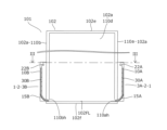
- FIG. 2 is a cross-sectional view taken along line II-II in FIG.
- FIG. 3 is a sectional view taken along line III-III in FIG. 2.
- the elevator 100 includes a car 101 on which passengers can ride, a water absorption mat device 1, a counterweight 103, a hoist 104, a deflection wheel 105, a main rope 106, an elevator control device (not shown), and a plurality of components. It has an operation panel 115.
- the car 101 and the counterweight 103 are connected to each other by a main rope 106.
- One end of the main rope 106 is connected to the top of the car 101.
- the other end of the main rope 106 is connected to the upper part of the counterweight 103.
- the hoist 104 has a driving sheave (not shown), and a main rope 106 is wound around the driving sheave and the deflecting sheave 105. Inside the hoistway 120, a car 101 and a counterweight 103 are suspended by a main rope 106.
- the car 101 and the counterweight 103 can move vertically inside the hoistway 120 according to the operation of the hoist 104.
- the car 101 is stopped at a stop position corresponding to the landing on the first floor, which is the lowest floor.
- the elevator control device controls the operation of the car 101 by controlling the hoisting machine 104 based on signals from each operation panel 115.
- Each operation panel 115 is installed at a landing on each floor.
- a passenger in the elevator 100 can move the car 101 to the landing floor where the passenger is waiting.
- the car 101 has a car body 102 and a car door (not shown).
- the car body 102 includes a wall 102a, a car ceiling member 102e, and a car floor member 102f.
- the wall 102a has a first side wall 110a, a second side wall 110b, a front wall 110c, and a back wall 110d.
- the first side wall 110a and the second side wall 110b are arranged to face each other.
- the front wall 110c is connected to each of the landing side ends of the first side wall 110a and the second side wall 110b.
- the back wall 110d is connected to each of the ends of the first side wall 110a and the second side wall 110b on the side opposite to the landing area.
- the front wall 110c and the back wall 110d are arranged to face each other.
- the car ceiling member 102e closes the upper part of the space surrounded by the first side wall 110a, the second side wall 110b, the front wall 110c, and the back wall 110d.
- the car floor member 102f closes the lower part of the space surrounded by the first side wall 110a, the second side wall 110b, the front wall 110c, and the back wall 110d.
- the surface of the car floor member 102f inside the car 101 is a floor surface 102FL.
- a first opening 110ah which is an opening, is formed at the lower end of the first side wall 110a.
- a second opening 110bh which is an opening, is formed at the lower end of the second side wall 110b.
- the front wall 110c is provided with an opening 110g.
- the car door can block the entrance/exit 110g.
- the elevator control device moves the car door to open the entrance/exit 110g.
- the doorway 110g is open, passengers can pass through the doorway 110g to go back and forth between the interior of the car 101 and the platform.
- the water-absorbing mat device 1 includes a water-absorbing mat mechanism 2 and an operation section 5 that drives the water-absorbing mat mechanism 2.
- the water absorption mat mechanism 2 includes a first mat unit 3A and a second mat unit 3B.
- the first mat unit 3A is arranged on the outside of the car 101 and on the side surface of the first side wall 110a.
- the first mat unit 3A includes a first housing 10A, a first moving mechanism 20A, a first water absorbing mat 30A, and a first control section 50A.
- FIG. 4 is a perspective view showing the first housing 10A of FIG. 2.
- FIG. 4 shows the first housing 10A viewed from the first side wall 110a side.
- the shape of the first housing 10A is a rectangular parallelepiped.
- the first housing 10A includes a pair of first housing vertical plate members 11A, a pair of first housing horizontal plate members 12A, a first housing side wall 13A, and a first guide plate 15A. There is.
- the pair of first housing vertical plate members 11A and the pair of first housing horizontal plate members 12A are arranged so as to protrude in the normal direction of the outer surface of the first side wall 110a.
- the pair of first casing vertical plate members 11A are arranged such that the longitudinal direction of each first casing vertical plate member 11A is along the vertical direction.
- the pair of first case horizontal plate members 12A are arranged such that the longitudinal direction of each first case horizontal plate member 12A is along the horizontal direction.
- the outer surface of the first side wall 110a When the outer surface of the first side wall 110a is viewed from the normal direction to the outer surface of the first side wall 110a, the outer surface of the first side wall 110a includes a pair of first housing vertical plate members 11A, A rectangular space is formed surrounded by the pair of first housing horizontal plate members 12A.
- the first housing side wall 13A is arranged to face the first side wall 110a.
- the first housing side wall 13A is arranged along the respective ends of the pair of first housing vertical plate members 11A and the pair of first housing horizontal plate members 12A.
- the first housing side wall 13A closes a rectangular space surrounded by the pair of first housing vertical plate members 11A and the pair of first housing horizontal plate members 12A.
- a first housing through hole 14A is provided at each of the upper end portions of the pair of first housing vertical plate members 11A.
- the first guide plate 15A is a long plate material.
- the first guide plate 15A is arranged at the lower end inside the space surrounded by the first side wall 110a and the first housing 10A.
- the first guide plate 15A is arranged such that the longitudinal direction of the first guide plate 15A is along the horizontal direction.
- first guide plate 15A One side along the longitudinal direction of the first guide plate 15A is arranged on the side of the first housing side wall 13A, and the other side along the longitudinal direction is arranged on the side of the first side wall 110a.
- the first guide plate 15A is arranged so as to be inclined downward from the first housing side wall 13A toward the first side wall 110a.
- the first guide plate 15A is curved when viewed along the longitudinal direction.
- the first guide plate 15A is arranged so that the curve of the first guide plate 15A extends from the inside of the car 101 to the outside.
- the first guide plate 15A is curved when viewed along the longitudinal direction, but the first guide plate 15A is bent at one or more places by bending to form a curved shape. may have been done.
- the first moving mechanism 20A includes a first motor 21A, a first shaft 22A connected to a rotating shaft of the first motor 21A, and a first torque sensor 23A as a first detector.
- the first moving mechanism 20A moves the first water absorbing mat 30A.
- the first motor 21A is supported on the outside of the first housing 10A.
- the first motor 21A is operated by power supplied from a power supply means (not shown). Control of the first motor 21A is performed by the first control section 50A.
- the first control unit 50A will be explained later.
- the first shaft 22A is passed through a pair of first housing through holes 14A and supported by the first housing 10A. Both ends of the first shaft 22A are rotatably supported by the pair of first housing through holes 14A.
- the first shaft 22A may be supported by each first housing through hole 14A via a bearing member.
- the rotational motion of the first motor 21A is transmitted from the rotation shaft of the first motor 21A to the first shaft 22A. Due to the rotational movement of the first motor 21A, the first shaft 22A rotates around the axis of the first shaft 22A.
- the first torque sensor 23A detects rotational torque related to the first shaft 22A.
- the rotational torque detected by the first torque sensor 23A is transmitted to the first control unit 50A through wiring (not shown).
- the first control unit 50A controls the first motor 21A based on the detection result of the first torque sensor 23A.
- the control method of the first control section 50A will be explained later.
- a transmission mechanism such as a transmission made of a member such as a gear may be further provided between the rotating shaft of the first motor 21A and the first shaft 22A.
- the first water absorbing mat 30A is a sheet-like member.
- FIG. 5 is a top view showing the first water-absorbing mat 30A of FIG. 2.
- FIG. 6 is a bottom view showing the first water-absorbing mat 30A of FIG. 2.
- the first water-absorbing mat 30A includes a first water-absorbing mat main body 31A, a first contact member 32A installed on the back surface of the first water-absorbing mat main body 31A, a first connecting portion 33A, and a plurality of first winding members. It has a first wire 34A.
- the first water-absorbing mat main body 31A includes a plurality of first water-absorbing plates 40A lined up in the moving direction of the first water-absorbing mat 30A, and a first connecting member (not shown) that connects each of the plurality of first water-absorbing plates 40A to each other. have.
- Each first water absorbing plate 40A is a long plate material. In this embodiment, eight first water absorption plates 40A are used.
- the first water absorbing plates 40A are connected to each other by a first connecting member in a direction perpendicular to the respective longitudinal directions. By bending the first connecting member between the connected adjacent first water absorbing plates 40A, the first water absorbing mat main body 31A can be bent in the direction in which the first water absorbing plates 40A are lined up.
- the first water absorption plate 40A is a plate material containing a diatomaceous earth component.
- the first water absorption plate 40A is formed by firing diatomaceous earth.
- Diatomaceous earth is a deposit made up of the remains of diatoms.
- Diatomaceous earth is a porous material whose main component is silicon dioxide hydrate.
- Diatomaceous earth component has excellent water absorption and hygroscopicity.
- the first water-absorbing plate 40A has better water absorption and hygroscopicity than a diatomaceous earth component, a water-absorbing material, or a plate material that does not contain a moisture-absorbing material.
- the coefficient of friction between the first contact member 32A and the floor surface 102FL of the car 101 is smaller than the coefficient of friction between the first water-absorbing mat body 31A and the floor surface 102FL of the car 101.
- the first contact members 32A are five steel tapes.
- the first connecting portion 33A is arranged at one end of the first water absorbing mat main body 31A.
- the first connecting portion 33A includes a first connecting portion main body 45A and a plurality of first magnets 46A that are first connecting members.
- the first connecting portion main body 45A is a plate material having the same length as the first water absorption plate 40A.
- a plurality of first magnets 46A are arranged on the side surface of the first connection portion main body 45A opposite to the side surface facing the first water absorption plate 40A.
- each first wire 34A is connected to the end of the first water-absorbing mat main body 31A opposite to the end where the first connecting portion 33A is arranged. In this embodiment, seven first wires 34A are used.
- the end where the first connecting portion 33A is installed is the tip of the first water absorbing mat 30A.
- each first wire 34A opposite to the end connected to the first water-absorbing mat main body 31A is connected to the first shaft 22A.
- the first control section 50A is supported by the first motor 21A.
- the first control section 50A controls the first motor 21A based on the signal from the operation section 5. Note that, although the first control unit 50A is supported by the first motor 21A, it is not limited to this and may be installed anywhere.
- the second mat unit 3B is arranged on the outside of the car 101 and on the side surface of the second side wall 110b.
- the second mat unit 3B differs from the first mat unit 3A only in that it is disposed on the second side wall 110b. Therefore, in the above description of the first mat unit 3A, the prefix "first” is replaced with “second”, the last symbol “A” is replaced with “B”, and “first side wall 110a” is replaced with “second”.
- the explanation replaced with "second side wall 110b" is the explanation of the second mat unit 3B.
- FIG. 7 is a front view showing the operation panel 115 of FIG. 1.
- the operation unit 5 is attached to at least one operation panel 115 among the plurality of operation panels 115.
- the operation unit 5 includes an operation button 60 and a wiring (not shown) that is a transmission member that transmits a signal from the operation button 60.
- the operation button 60 is arranged on at least one operation panel 115 among the plurality of operation panels 115.
- a contact signal from the operation button 60 is input to the first control section 50A and the second control section 50B via wiring.
- the water absorbing mat device 1 is operated by a building manager. Therefore, the operation button 60 is arranged on an operation panel 115 installed at the platform on the floor where the building manager's room is located. In this embodiment, the operation panel 115 on which the operation buttons 60 are arranged is installed on the lowest landing floor.
- first water-absorbing mat 30A and the second water-absorbing mat 30B show a state in which the first water absorbent mat 30A is in the first retracted position and the second water absorbent mat 30B is in the second retracted position. That is, the first water-absorbing mat 30A is drawn into the first housing 10A, and the second water-absorbing mat 30B is drawn into the second housing 10B.
- Each first wire 34A is wound around the first shaft 22A by the rotation of the first motor 21A and the first shaft 22A. Since each first wire 34A is wound up, the first water absorbing mat 30A is housed in the internal space of the first housing 10A. That is, the first water-absorbing mat 30A is located on the back side of the first side wall 110a of the car 101. In this state, the first water-absorbing mat 30A is in the first retracted position.
- Each second wire 34B is wound around the second shaft 22B by the rotation of the second motor 21B and the second shaft 22B. Since each second wire 34B is wound up, the second water-absorbing mat 30B is housed in the internal space of the second housing 10B. That is, the second water-absorbing mat 30B is located on the back side of the second side wall 110b of the car 101. In this state, the second water-absorbing mat 30B is in the second retracted position.
- FIG. 8 is a sectional view showing a state in which the first water-absorbing mat 30A of FIG. 2 is in the first laying position and the second water-absorbing mat 30B is in the second laying position.
- FIG. 9 is a cross-sectional view taken along line IX-IX in FIG. 8, showing a state in which the first water-absorbing mat 30A in FIG. 3 is in the first laying position and the second water-absorbing mat 30B is in the second laying position.
- each first wire 34A is unwound from the first shaft 22A.
- the first water-absorbing mat main body 31A comes out from the first housing 10A.
- the first water-absorbing mat body 31A passes through the first opening 110ah, is sent out from the first housing 10A, and covers the floor surface 102FL. That is, the first water-absorbing mat main body 31A is placed on the floor surface 102FL of the car 101. In this state, the first water absorbing mat 30A is in the first installation position.
- each second wire 34B is unwound from the second shaft 22B due to the rotation of the second motor 21B and the second shaft 22B.
- the second water absorption mat main body 31B comes out from the second housing 10B.
- the second water-absorbing mat body 31B passes through the second opening 110bh, is sent out from the second housing 10B, and covers the floor surface 102FL. That is, the second water-absorbing mat main body 31B is placed on the floor surface 102FL of the car 101. In this state, the second water-absorbing mat 30B is in the second installation position.
- the first water-absorbing mat 30A and the second water-absorbing mat 30B are lined up with each other on the floor surface 102FL of the car 101. There is. The tip of the first water-absorbing mat 30A and the tip of the second water-absorbing mat 30B are in contact with each other.
- the first water-absorbing mat 30A and the second water-absorbing mat 30B that are in contact with each other are connected to each other by the magnetic force of the first magnet 46A and the second magnet 46B. That is, the first connecting portion 33A and the second connecting portion 33B are removably connected to each other.
- a worker such as a manager of the elevator 100 determines whether or not to drive the water-absorbing mat device 1 based on environmental conditions such as rainfall conditions.
- the worker determines that it is necessary to drive the water absorption mat device 1, the worker operates the operation button 60. That is, the worker presses the operation button 60.
- the first control section 50A and the second control section 50B are able to control the information when the operation button 60 is pressed. Understand that the state is
- the first control unit 50A knows whether the first water absorbing mat 30A is in the first retracted position or the first laying position. When detecting that the operation button 60 is pressed, the first control unit 50A determines the position of the first water absorbing mat 30A.
- the first control unit 50A determines that the first water-absorbing mat 30A is in the first retracted position, the first control unit 50A rotates the first motor 21A in the sending direction.
- the rotational feeding direction of the first motor 21A is a direction in which the first water absorbing mat 30A moves from the first retracted position to the first laying position, that is, the first water absorbing mat 30A is sent out from the first housing 10A. is the direction of rotation. Note that in the rotation direction of the first shaft 22A, the feeding direction is also the rotation direction in the same direction.
- the rotational force of the first motor 21A is transmitted to the first shaft 22A.
- the first shaft 22A rotates in the delivery direction around its axis. As a result, each first wire 34A wound around the first shaft 22A is unwound.
- the first water-absorbing mat 30A moves in the direction of being pushed out from the first housing 10A.
- the first water-absorbing mat 30A has the following forces: the force of gravity acting on the first water-absorbing mat 30A itself, and the force acting in the direction of unraveling each first wire 34A and pushing out the first water-absorbing mat 30A from the first casing 10A. is working. These forces move the first water-absorbing mat 30A in a direction in which it is pushed out from the first housing 10A.
- the first contact member 32A installed on the back surface of the first water-absorbing mat 30A contacts the first guide plate 15A. Thereby, the first water-absorbing mat 30A moves smoothly along the first guide plate 15A.
- the first water-absorbing mat 30A passes through the first opening 110ah and moves on the floor surface 102FL of the car 101.
- the first contact member 32A is in contact with the floor surface 102FL of the car 101.
- the first water absorbent mat 30A when the first water absorbent mat 30A is continuously fed out from the first housing 10A, the first water absorbent mat 30A eventually reaches the first laying position.
- the first water-absorbing mat 30A When the first water-absorbing mat 30A is located at the first installation position, the first water-absorbing mat 30A is arranged to cover the floor surface 102FL of the car 101.
- the second water-absorbing mat 30B in the second retracted position is also sent out from the second housing 10B. Eventually, the second water-absorbing mat 30B passes through the second opening 110bh and reaches the second installation position.
- the first connecting part 33A and the second connecting part 33B are in contact with each other.
- the detected torque of the first torque sensor 23A and the detected torque of the second torque sensor 23B vary.
- the first control unit 50A recognizes that the first water absorbing mat 30A has reached the first installation position based on the behavior of the detected torque from the first torque sensor 23A. Thereby, the first control unit 50A stops the rotation of the first motor 21A.
- the first control unit 50A stores in a storage area (not shown) in the first control unit 50A that the first water absorbing mat 30A has reached the first laying position. This completes the movement of the first water-absorbing mat 30A to the installation position.
- the second control unit 50B recognizes that the second water-absorbing mat 30B has reached the second installation position based on the behavior of the detected torque from the second torque sensor 23B. Thereby, the second control unit 50B stops the rotation of the second motor 21B.
- the second control unit 50B stores in a storage area (not shown) in the second control unit 50B that the second water absorbing mat 30B has reached the second laying position.
- the first control unit 50A detects that the operation button 60 is pressed when the first water-absorbing mat 30A is in the first laying position, it rotates the first motor 21A in the winding direction.
- the winding direction is a rotation direction opposite to the feeding direction.
- the winding direction which is the rotating direction of the first motor 21A
- the first water absorbent mat 30A is This is the direction of rotation for moving toward the inside of the housing 10A. Note that in the rotation direction of the first shaft 22A, the winding direction is also the same rotation direction.
- the rotational force of the first motor 21A is transmitted to the first shaft 22A.
- the first shaft 22A rotates around its axis in the winding direction. Thereby, each first wire 34A is wound around the first shaft 22A.
- the first water-absorbing mat 30A moves on the floor surface 102FL of the car 101 and passes through the first opening 110ah toward the first housing 10A. move in the direction.
- the first contact member 32A installed on the back surface of the first water-absorbing mat 30A contacts the floor surface 102FL of the car 101 and the first guide plate 15A. Thereby, the first water-absorbing mat 30A moves smoothly along the floor surface 102FL of the car 101 and the first guide plate 15A.
- each first wire 34A is entirely wound around the first shaft 22A.
- the first water-absorbing mat 30A reaches the first retracted position.
- the first water absorption mat main body 31A does not cover the floor surface 102FL of the car 101, but is placed inside the first housing 10A.
- the first control unit 50A recognizes that the first water absorbing mat 30A has reached the first retracted position based on the behavior of the detected torque from the first torque sensor 23A. Thereby, the first control unit 50A stops the rotation of the first motor 21A.
- the first control unit 50A stores the fact that the first water-absorbing mat 30A has reached the first retracted position in a storage area (not shown) within the first control unit 50A. This completes the movement of the first water-absorbing mat 30A to the first retracted position.
- the second water-absorbing mat 30B when the operation button 60 is pressed, the second water-absorbing mat 30B also moves to the second housing 10B through the second opening 110bh. Eventually, the second water-absorbing mat 30B reaches the second installation position.
- the second control unit 50B recognizes that the second water-absorbing mat 30B has reached the second retracted position based on the behavior of the detected torque from the second torque sensor 23B. Thereby, the second control unit 50B stops the rotation of the second motor 21B.
- the second control unit 50B stores the fact that the second water-absorbing mat 30B has reached the second retracted position in a storage area (not shown) within the second control unit 50B. This completes the movement of the second water-absorbing mat 30B to the second retracted position.
- the water-absorbing mat device 1 includes a water-absorbing mat mechanism 2 installed in a car 101 and an operation unit 5 that drives the water-absorbing mat mechanism 2. Further, the water absorbing mat mechanism 2 includes a first mat unit 3A, and the first mat unit 3A includes a first water absorbing mat 30A and a first moving mechanism 20A that moves the first water absorbing mat 30A. ing. Further, the first water absorption mat 30A is movable between a first retracted position located on the back side of the first side wall 110a of the car 101 and a first installation position where it is laid on the floor surface 102FL of the car 101. ing.
- the first moving mechanism 20A moves the first water absorbing mat 30A between the first retracted position and the first laying position when the operating section 5 is operated.
- the first water-absorbing mat 30A has a first water-absorbing mat main body 31A including a porous material.
- the operator can lay down the first water-absorbing mat 30A on the floor surface 102FL by operating the operation unit 5 according to the rain situation. Therefore, rainwater and moisture inside the car 101 can be absorbed into the first water-absorbing mat 30A. Therefore, the humidity inside the car 101 can be maintained at an appropriate level, and the comfort inside the car 101 can be improved.
- the first water-absorbing mat 30A has excellent water-absorbing properties and quick-drying properties, it can quickly absorb moisture from the floor surface 102FL.
- the comfort inside the car 101 can be improved. Moreover, this makes it possible to reduce contamination of the floor surface 102FL with rainwater containing mud during rainfall. Furthermore, scratches and damage to the floor surface 102FL caused by umbrellas brought in by passengers of the elevator 100 can be reduced. Further, rainwater and moisture inside the basket 101 can be absorbed by the first water-absorbing mat main body 31A including a porous material. Therefore, the moisture inside the cage 101 and the ability to remove moisture can be improved. Further, the operator can retreat the first water absorbing mat 30A to the back side of the first side wall 110a of the car 101 by operating the operation unit 5 when the rain ends. Therefore, the first water-absorbing mat 30A containing the porous material can be dried outside the basket 101.
- the dried first water-absorbing mat 30A can be used again, and the moisture inside the basket 101 and the ability to remove moisture can be improved. Furthermore, this allows the worker to use mechanical power to lay down the first water-absorbing mat 30A on the floor surface 102FL when it rains. Therefore, the workload of the worker can be reduced. Moreover, the first water absorbing mat 30A can be laid down on the floor surface 102FL more quickly.
- the first water-absorbing mat main body 31A includes a plurality of first water-absorbing plates 40A that are connected to each other and lined up in the moving direction of the first water-absorbing mat 30A. Furthermore, the first water-absorbing mat main body 31A can be bent between adjacent first water-absorbing plates 40A in the direction in which the plurality of first water-absorbing plates 40A are lined up. Thereby, a plate material containing porous material at a higher density can be used. Therefore, the moisture inside the cage 101 and the ability to remove moisture can be improved.
- the porous material contained in the first water-absorbing mat body 31A is diatomaceous earth.
- diatomaceous earth with excellent water absorption and hygroscopicity can be used by the first water absorption mat main body 31A. Therefore, the moisture inside the cage 101 and the ability to remove moisture can be improved.
- the first water-absorbing mat 30A has the first contact member 32A installed on the first water-absorbing mat main body 31A. Further, when the first water absorbing mat 30A is located at the first installation position, the first contact member is in contact with the floor surface 102FL. Further, the coefficient of friction between the floor surface 102FL and the first contact member 32A is smaller than the coefficient of friction between the floor surface 102FL and the first water-absorbing mat body 31A. Thereby, the first water-absorbing mat 30A can move more smoothly on the floor surface 102FL. Therefore, a smaller motor can be used as the first motor 21A. Furthermore, damage to the floor surface 102FL due to movement of the first water-absorbing mat 30A can be reduced.
- the first opening 110ah is located at the lower end of the first side wall 110a.
- the inner surface of the first side wall 110a of the car 101 is a continuous large surface without being partitioned by the first opening 110ah. Therefore, the design of the cage 101 is improved. Furthermore, passengers in the elevator 100 are less likely to notice the first opening 110ah, and the design of the car 101 is improved.
- the first opening 110ah is located at a higher position than the floor surface 102FL. Further, the height distance from the floor surface 102FL to the lower end of the first opening 110ah is 15 cm or more.
- the first water-absorbing mat 30A covers the lower end of the inner surface of the first side wall 110a up to a height of 15 cm or more from the floor surface 102FL. Therefore, it is possible to reduce contamination of the lower end portion of the inner surface of the first side wall 110a with rainwater containing mud during rain. Furthermore, scratches and damage to the lower end portion of the inner surface of the first side wall 110a caused by umbrellas brought by passengers in the elevator 100 can be reduced.
- the first water-absorbing mat 30A has the first connecting portion 33A installed at the end of the first water-absorbing mat main body 31A. Further, when the first water absorbing mat 30A is located at the first installation position, the first connecting portion 33A is removably connected to a part of the car 101. Therefore, the positional shift of the first water-absorbing mat 30A can be reduced.
- the first connecting portion 33A includes a magnet. Therefore, the first connecting portion 33A can be manufactured using easily available members.
- the water-absorbing mat device 1 includes the second mat unit 3B, and the second mat unit 3B includes a second water-absorbing mat 30B and a second water-absorbing mat 30B. It has a second moving mechanism 20B for moving. Further, the second water-absorbing mat 30B is movable between a second retracted position located on the back side of the second side wall 110b and a second laid-down position laid on the floor surface 102FL. The second moving mechanism 20B moves the second water-absorbing mat 30B between the second retracted position and the second laying position when the operating section 5 is operated.
- the first water absorbent mat 30A is located at the first installation position and the second water absorption mat 30B is located at the second installation position
- the first water absorption mat 30A and the second water absorption mat 30B are placed on the floor. They are lined up with each other at 102FL.
- the second water-absorbing mat 30B has a second water-absorbing mat main body 31B containing a porous material.
- the operator can lay down the first water-absorbing mat 30A and the second water-absorbing mat 30B on the floor surface 102FL by operating the operation unit 5 according to the rain situation. Therefore, rainwater and moisture inside the car 101 can be absorbed into the first water-absorbing mat 30A and the second water-absorbing mat 30B.
- the humidity inside the car 101 can be maintained at an appropriate level, and the comfort inside the car 101 can be improved. Furthermore, since the first water absorbing mat 30A and the second water absorbing mat 30B have excellent water absorbing properties and quick drying properties, they can quickly absorb moisture from the floor surface 102FL. Therefore, the comfort inside the car 101 can be improved. Moreover, this makes it possible to reduce contamination of the floor surface 102FL with rainwater containing mud during rainfall. Furthermore, scratches and damage to the floor surface 102FL caused by umbrellas brought in by passengers of the elevator 100 can be reduced. Further, rainwater and moisture inside the basket 101 can be absorbed into the first water-absorbing mat main body 31A and the second water-absorbing mat main body 31B including a porous material.
- the moisture inside the cage 101 and the ability to remove moisture can be improved.
- the operator operates the operation unit 5 to retreat the first water absorbent mat 30A to the back side of the first side wall 110a of the car 101, and moves the second water absorbent mat 30B to the back side of the first side wall 110a of the car 101. It can be evacuated to the back side of the second side wall. Therefore, the first water-absorbing mat 30A and the second water-absorbing mat 30B containing the porous material can be dried outside the basket 101. Therefore, the dried first water-absorbing mat 30A can be used again, and the moisture inside the basket 101 and the ability to remove moisture can be improved.
- the first water absorbent mat 30A and the second water absorbent mat 30B can be laid down on the floor surface 102FL more quickly.
- the first mat unit 3A which includes parts such as a housing, a motor, and a shaft
- the second mat unit 3B can be downsized.
- the second water-absorbing mat main body 31B includes a plurality of second water-absorbing plates 40B that are connected to each other and lined up in the moving direction of the second water-absorbing mat 30B.
- the second water-absorbing mat main body 31B is bendable between adjacent second water-absorbing plates 40B in the direction in which the plurality of second water-absorbing plates 40B are lined up. Therefore, a plate material containing porous material at a higher density can be used. Therefore, the moisture inside the cage 101 and the ability to remove moisture can be improved.
- the porous material contained in the second water-absorbing mat main body 31B is diatomaceous earth.
- diatomaceous earth with excellent water absorption and hygroscopicity can be used by the second water absorption mat main body 31B. Therefore, the moisture inside the cage 101 and the ability to remove moisture can be improved.
- the first water-absorbing mat 30A has the first connecting portion 33A
- the second water-absorbing mat 30B has the second connecting portion 33B.
- the first connecting portion 33A and the second connecting portion 33B are removed from each other. possible to be connected. Therefore, it is possible to reduce misalignment of the first water absorbing mat 30A and the second water absorbing mat 30B.
- each of the first connecting portion 33A and the second connecting portion 33B includes a magnet. Therefore, the first connecting portion 33A and the second connecting portion 33B can be manufactured using easily available members.
- the second opening 110bh is located at the lower end of the second side wall 110b.
- the inner surface of the second side wall 110b of the car 101 is a continuous large surface without being partitioned by the second opening 110bh. Therefore, the design of the cage 101 is improved. Furthermore, passengers in the elevator 100 are less likely to notice the second opening 110bh, and the design of the car 101 is improved.
- the second opening 110bh is located at a higher position than the floor surface 102FL, and the height distance from the floor surface 102FL to the lower end of the second opening 110bh is , 15 cm or more.
- the second water-absorbing mat main body 31B covers the lower end of the inner surface of the second side wall 110b up to a height of 15 cm or more from the floor surface 102FL. Therefore, it is possible to reduce contamination of the lower end portion of the inner surface of the second side wall 110b by rainwater containing mud during rain. Furthermore, scratches and damage to the lower end portion of the inner surface of the second side wall 110b caused by umbrellas brought in by passengers of the elevator 100 can be reduced.
- the operation unit 5 has one operation button 60, and the water-absorbing mat device 1 is driven when the operation button 60 is operated. Thereby, the operator can easily drive the water absorption mat device 1 by operating one operation button 60.
- the operation unit 5 is attached to an operation panel installed at an elevator landing. This allows the operator to easily operate the operation button 60.
- first water absorbing plate 40A and the second water absorbing plate 40B of Embodiment 1 contain a diatomaceous earth component. However, it is not limited to this.
- the first water absorbing plate 40A and the second water absorbing plate 40B may include a material with excellent water absorbing properties. For example, a porous material may be used as the material with excellent water absorption.
- first water-absorbing mat main body 31A of the first embodiment has eight first water-absorbing plates 40A
- second water-absorbing mat main body 31B has eight second water-absorbing plates 40B.
- Flexible sheet materials may be used as the first water-absorbing mat body 31A and the second water-absorbing mat body 31B.
- a sheet material may be used in which a porous material, preferably a material containing a diatomaceous earth component, is adhered to or contained in the base material of the sheet material. good.
- a porous material preferably a material containing a diatomaceous earth component
- first connecting member and the second connecting member of Embodiment 1 are well-known members that can connect a plurality of plate materials.
- members such as an adhesive tape, a hook-and-loop fastener, and a hinge may be used as the first connecting member.
- a bag-like member may be used as the first connecting member. Inside the bag-like member, compartments are formed as many as the number of first water absorbing plates 40A, and one compartment can accommodate the first water absorbing plates 40A. By inserting the first water absorbing plates 40A into each section, the first water absorbing plates 40A are connected so as to be lined up in a direction perpendicular to the longitudinal direction of each of the first water absorbing plates 40A.
- first contact member 32A may also be used as the first connection member.
- Each of the first water absorbing plates 40A may be connected to each other by pasting each first contact member 32A across each of the first water absorbing plates 40A.
- each of the first water absorbing plates 40A may be connected by arranging any one of the plurality of first wires 34A across each of the first water absorbing plates 40A.
- the second connecting member can also have the same configuration as the first connecting member.
- the first contact member 32A of the first embodiment is five steel tapes. However, it is not limited to this. For example, four or less steel tapes, or six or more steel tapes may be used.
- the first contact member 32A may be a member made of a resin such as fluororesin exposed to the floor surface 102FL of the car 101.
- a plurality of rollers may be used as the first contact member 32A.
- the first water-absorbing mat 30A can move more smoothly on the floor surface 102FL. Therefore, a smaller motor can be used as the first motor 21A. Furthermore, damage to the floor surface 102FL due to movement of the first water-absorbing mat 30A can be reduced.
- the water absorbing mat device 1 of the first embodiment includes a first mat unit 3A and a second mat unit 3B.
- the water absorbing mat device 1 may include only one of the first mat unit 3A and the second mat unit 3B.
- the water absorbing mat device 1 may include only the first mat unit 3A.
- the first connecting portion 33A may be in contact with the second side wall 110b. That is, the first connecting portion 33A may be removably connected to the inside of the second side wall 110b by magnetic force.
- the water-absorbing mat device 1 may include only the first mat unit 3A disposed outside the back wall 110d. In this case, the first opening 110ah is formed in the back wall 110d.
- first magnets 46A are arranged in the first connection part 33A of the first embodiment, and a plurality of second magnets 46B are arranged in the second connection part 33B.
- a mechanical connecting member such as a hook and loop fastener, a hook, or a button may be used for the first connecting portion 33A and the second connecting portion 33B.
- first connecting portion 33A and the second connecting portion 33B of the first embodiment are connected to each other.
- the first connecting portion 33A and the second connecting portion 33B may be connected to any part inside the car 101.
- it may be connected to the floor surface 102FL or a part of the rear wall 110d.
- the first torque sensor 23A is used as the first detector in the first embodiment, and the second torque sensor 23B is used as the second detector.
- a limit switch or a photosensor may be used as the first detector and the second detector.
- the positions of the first water-absorbing mat 30A and the second water-absorbing mat 30B can also be detected using a limit switch or a photosensor.
- encoders that detect the respective rotation amounts of the first shaft 22A and the second shaft 22B may be arranged as the first detector and the second detector.
- the respective positions of the first water-absorbing mat 30A and the second water-absorbing mat 30B may be grasped by calculating the moving distances of the first water-absorbing mat 30A and the second water-absorbing mat 30B based on the output of each encoder.
- the first control section 50A and the second control section 50B of the first embodiment each perform control independently based on the state in which the operation button 60 is pressed.
- the first control unit 50A and the second control unit 50B may perform control after mutually recognizing each other's operating status and storage area information. For example, when the operation button 60 is pressed, if the positions of the first water absorption mat 30A and the second water absorption mat 30B are different from each other, the first control section 50A and the second control section 50B control the first motor 21A. Also, the second motor 21B may not be operated. Thereby, the water absorption mat device 1 can be driven more safely.
- first control unit 50A and the second control unit 50B of the first embodiment store the position of the first water absorption mat 30A or the second water absorption mat 30B in a storage area (not shown).
- a limit switch or a photosensor may be arranged to detect the positions of the first water-absorbing mat 30A and the second water-absorbing mat 30B.
- the operating status of the water absorbing mat device 1 may be displayed on the operation button 60 of the first embodiment.
- a lighting device may be disposed inside the operation button 60, and the operating status of the water absorbing mat device 1 may be displayed based on the lighting state of the lighting device.
- a light may be turned on inside the operation button 60.
- the interior of the operation button 60 may be illuminated on and off.
- the water absorbing mat device 1 of the first embodiment has an operation button 60 exposed on the surface of the operation panel 115.
- the operation button 60 may be arranged in a space closed by a lid within the wall of the landing, or in a space closed by a lid inside the car 101. Further, for example, the operation button 60 may be placed in the management room of the building. Alternatively, the operation button 60 may be arranged inside the control panel of the elevator 100.
- the water absorbing mat device 1 of the first embodiment has an operation button 60.
- a drive signal may be transmitted to the water-absorbing mat device 1 by pressing buttons that are standardly equipped on the operation panel 115 in a preset order. Thereby, there is no need to specially install the operation button 60 on the operation panel 115.
- the water absorbing mat device 1 of the first embodiment has one operation button 60.
- it is not limited to this.
- it may have two operation buttons corresponding to each of the first mat unit 3A and the second mat unit 3B.
- the first opening 110ah in the first embodiment is formed at the lower end of the first side wall 110a
- the second opening 110bh is formed at the lower end of the second side wall 110b.
- the first opening 110ah and the second opening 110bh may be formed above the lower ends of the corresponding first side wall 110a and second side wall 110b.
- the first opening 110ah and the second opening 110bh may be located at a position higher than the floor surface 102FL of the car 101.
- the distance in the height direction from the floor surface 102FL of the car 101 to the lower ends of the first opening 110ah and the second opening 110b may be 15 cm or more.
- the elevator 100 of the first embodiment is operated with the first water-absorbing mat 30A in the first installation position and the second water-absorbing mat 30B in the second installation position.
- the stopping position corresponding to each floor of the car 101 may be changed.
- the thickness of the first water-absorbing mat 30A is smaller than the standard stopping position of the car 101.
- the stop position of the car 101 may be set to a position lower by that amount.
- the standard stopping position of the car 101 is the stopping position of the car 101 when the first water-absorbing mat 30A is at the first retracted position and the second water-absorbing mat 30B is at the second retracted position.
- 1 Water absorption mat device 2 Water absorption mat mechanism, 3A First mat unit, 3B Second mat unit, 5 Operation section, 10A First housing, 10B Second housing, 11A First housing vertical plate member, 12A First Housing horizontal plate member, 13A first housing side wall, 14A first housing through hole, 15A first guide plate, 15B second guide plate, 20A first moving mechanism, 20B second moving mechanism, 21A first motor, 21B second motor, 22A first shaft, 22B second shaft, 23A first torque sensor (first detector), 23B second torque sensor (second detector), 30A first water absorption mat, 30B second water absorption mat , 31A first water absorption mat body, 31B second water absorption mat body, 32A first contact member, 33A first connection part, 33B second connection part, 34A first wire (first winding member), 34B second wire ( 2nd winding member), 40A first water absorption plate, 40B second water absorption plate, 45A first connection body, 46A first magnet, 46B second magnet, 50A first control section, 50B second control section, 60 operation Buttons
Landscapes
- Engineering & Computer Science (AREA)
- Civil Engineering (AREA)
- Mechanical Engineering (AREA)
- Structural Engineering (AREA)
- Passenger Equipment (AREA)
Priority Applications (2)
| Application Number | Priority Date | Filing Date | Title |
|---|---|---|---|
| JP2024542560A JPWO2024042715A1 (https=) | 2022-08-26 | 2022-08-26 | |
| PCT/JP2022/032246 WO2024042715A1 (ja) | 2022-08-26 | 2022-08-26 | エレベーターの吸水マット装置 |
Applications Claiming Priority (1)
| Application Number | Priority Date | Filing Date | Title |
|---|---|---|---|
| PCT/JP2022/032246 WO2024042715A1 (ja) | 2022-08-26 | 2022-08-26 | エレベーターの吸水マット装置 |
Publications (1)
| Publication Number | Publication Date |
|---|---|
| WO2024042715A1 true WO2024042715A1 (ja) | 2024-02-29 |
Family
ID=90012946
Family Applications (1)
| Application Number | Title | Priority Date | Filing Date |
|---|---|---|---|
| PCT/JP2022/032246 Ceased WO2024042715A1 (ja) | 2022-08-26 | 2022-08-26 | エレベーターの吸水マット装置 |
Country Status (2)
| Country | Link |
|---|---|
| JP (1) | JPWO2024042715A1 (https=) |
| WO (1) | WO2024042715A1 (https=) |
Citations (7)
| Publication number | Priority date | Publication date | Assignee | Title |
|---|---|---|---|---|
| JPS63133567U (https=) * | 1987-02-20 | 1988-09-01 | ||
| JPH0422473U (https=) * | 1990-06-18 | 1992-02-25 | ||
| JPH08337378A (ja) * | 1995-06-12 | 1996-12-24 | Mitsubishi Denki Bill Techno Service Kk | エレベーター用カゴ室 |
| JP2000211856A (ja) * | 1999-01-25 | 2000-08-02 | Mitsubishi Electric Building Techno Service Co Ltd | エレベ―タ―のかご装置 |
| JP2014125310A (ja) * | 2012-12-26 | 2014-07-07 | Hitachi Ltd | エレベータ装置およびそのマット交換方法 |
| JP2019069302A (ja) * | 2019-02-07 | 2019-05-09 | 英三 大森 | 足拭きマット |
| US20200245845A1 (en) * | 2019-04-19 | 2020-08-06 | Dorai Home, Inc. | Absorptive drying implement |
-
2022
- 2022-08-26 JP JP2024542560A patent/JPWO2024042715A1/ja active Pending
- 2022-08-26 WO PCT/JP2022/032246 patent/WO2024042715A1/ja not_active Ceased
Patent Citations (7)
| Publication number | Priority date | Publication date | Assignee | Title |
|---|---|---|---|---|
| JPS63133567U (https=) * | 1987-02-20 | 1988-09-01 | ||
| JPH0422473U (https=) * | 1990-06-18 | 1992-02-25 | ||
| JPH08337378A (ja) * | 1995-06-12 | 1996-12-24 | Mitsubishi Denki Bill Techno Service Kk | エレベーター用カゴ室 |
| JP2000211856A (ja) * | 1999-01-25 | 2000-08-02 | Mitsubishi Electric Building Techno Service Co Ltd | エレベ―タ―のかご装置 |
| JP2014125310A (ja) * | 2012-12-26 | 2014-07-07 | Hitachi Ltd | エレベータ装置およびそのマット交換方法 |
| JP2019069302A (ja) * | 2019-02-07 | 2019-05-09 | 英三 大森 | 足拭きマット |
| US20200245845A1 (en) * | 2019-04-19 | 2020-08-06 | Dorai Home, Inc. | Absorptive drying implement |
Also Published As
| Publication number | Publication date |
|---|---|
| JPWO2024042715A1 (https=) | 2024-02-29 |
Similar Documents
| Publication | Publication Date | Title |
|---|---|---|
| EP0985627B1 (en) | Location of the controlling system | |
| JP2593288B2 (ja) | トラクションシーブエレベータ | |
| EP1016614B1 (en) | Controller for elevators | |
| JP2877745B2 (ja) | トラクションシーブエレベータとトラクションシーブエレベータ用機械空間 | |
| JP2992219B2 (ja) | トラクションシーブエレベータおよび巻上装置 | |
| UA78240C2 (en) | Traction sheave elevator, without machine room | |
| EP3135620A1 (en) | Elevator | |
| JP2011068428A (ja) | エレベータ | |
| JP3363711B2 (ja) | エレベータのかご扉のインターロック装置 | |
| WO2024042715A1 (ja) | エレベーターの吸水マット装置 | |
| JP2010120703A (ja) | エレベータ装置 | |
| EP1195346A1 (en) | Elevator device | |
| KR100899354B1 (ko) | 엘리베이터용 판낼 보양커튼 | |
| JPH0631145B2 (ja) | エレベ−タ装置 | |
| JP2010155664A (ja) | エレベータのドア装置 | |
| WO2005082763A1 (ja) | 樹脂製ロープとそれを用いたエレベータの位置検出装置 | |
| JP2001348171A (ja) | 昇降機のペイロードレセプタクルを移動させる補助装置 | |
| JP7352874B2 (ja) | 移動装置 | |
| WO2018179179A1 (ja) | エレベータ装置 | |
| JP7795726B1 (ja) | エレベータ電気盤及びエレベータ | |
| JP2010089918A (ja) | エレベータ | |
| JP2009155095A (ja) | エレベータのドア装置、およびエレベータの乗降構造体 | |
| JP4637603B2 (ja) | マルチカーエレベータ | |
| JP4454766B2 (ja) | エレベーターの昇降路装置 | |
| JP4387243B2 (ja) | エレベータの閉じ込め救出装置 |
Legal Events
| Date | Code | Title | Description |
|---|---|---|---|
| 121 | Ep: the epo has been informed by wipo that ep was designated in this application |
Ref document number: 22956541 Country of ref document: EP Kind code of ref document: A1 |
|
| WWE | Wipo information: entry into national phase |
Ref document number: 2024542560 Country of ref document: JP |
|
| NENP | Non-entry into the national phase |
Ref country code: DE |
|
| 122 | Ep: pct application non-entry in european phase |
Ref document number: 22956541 Country of ref document: EP Kind code of ref document: A1 |