WO2024038822A1 - 作業機 - Google Patents
作業機 Download PDFInfo
- Publication number
- WO2024038822A1 WO2024038822A1 PCT/JP2023/029231 JP2023029231W WO2024038822A1 WO 2024038822 A1 WO2024038822 A1 WO 2024038822A1 JP 2023029231 W JP2023029231 W JP 2023029231W WO 2024038822 A1 WO2024038822 A1 WO 2024038822A1
- Authority
- WO
- WIPO (PCT)
- Prior art keywords
- housing
- wall
- control unit
- controller
- fan
- Prior art date
- Legal status (The legal status is an assumption and is not a legal conclusion. Google has not performed a legal analysis and makes no representation as to the accuracy of the status listed.)
- Ceased
Links
Images


Classifications
-
- B—PERFORMING OPERATIONS; TRANSPORTING
- B25—HAND TOOLS; PORTABLE POWER-DRIVEN TOOLS; MANIPULATORS
- B25F—COMBINATION OR MULTI-PURPOSE TOOLS NOT OTHERWISE PROVIDED FOR; DETAILS OR COMPONENTS OF PORTABLE POWER-DRIVEN TOOLS NOT PARTICULARLY RELATED TO THE OPERATIONS PERFORMED AND NOT OTHERWISE PROVIDED FOR
- B25F5/00—Details or components of portable power-driven tools not particularly related to the operations performed and not otherwise provided for
- B25F5/008—Cooling means
-
- A—HUMAN NECESSITIES
- A01—AGRICULTURE; FORESTRY; ANIMAL HUSBANDRY; HUNTING; TRAPPING; FISHING
- A01D—HARVESTING; MOWING
- A01D34/00—Mowers; Mowing apparatus of harvesters
- A01D34/01—Mowers; Mowing apparatus of harvesters characterised by features relating to the type of cutting apparatus
- A01D34/412—Mowers; Mowing apparatus of harvesters characterised by features relating to the type of cutting apparatus having rotating cutters
- A01D34/416—Flexible line cutters
-
- A—HUMAN NECESSITIES
- A01—AGRICULTURE; FORESTRY; ANIMAL HUSBANDRY; HUNTING; TRAPPING; FISHING
- A01D—HARVESTING; MOWING
- A01D34/00—Mowers; Mowing apparatus of harvesters
- A01D34/01—Mowers; Mowing apparatus of harvesters characterised by features relating to the type of cutting apparatus
- A01D34/412—Mowers; Mowing apparatus of harvesters characterised by features relating to the type of cutting apparatus having rotating cutters
- A01D34/63—Mowers; Mowing apparatus of harvesters characterised by features relating to the type of cutting apparatus having rotating cutters having cutters rotating about a vertical axis
- A01D34/76—Driving mechanisms for the cutters
-
- A—HUMAN NECESSITIES
- A01—AGRICULTURE; FORESTRY; ANIMAL HUSBANDRY; HUNTING; TRAPPING; FISHING
- A01D—HARVESTING; MOWING
- A01D34/00—Mowers; Mowing apparatus of harvesters
- A01D34/835—Mowers; Mowing apparatus of harvesters specially adapted for particular purposes
-
- A—HUMAN NECESSITIES
- A01—AGRICULTURE; FORESTRY; ANIMAL HUSBANDRY; HUNTING; TRAPPING; FISHING
- A01D—HARVESTING; MOWING
- A01D75/00—Accessories for harvesters or mowers
- A01D75/18—Safety devices for parts of the machines
- A01D75/182—Avoiding overload
-
- A—HUMAN NECESSITIES
- A01—AGRICULTURE; FORESTRY; ANIMAL HUSBANDRY; HUNTING; TRAPPING; FISHING
- A01D—HARVESTING; MOWING
- A01D2101/00—Lawn-mowers
-
- A—HUMAN NECESSITIES
- A01—AGRICULTURE; FORESTRY; ANIMAL HUSBANDRY; HUNTING; TRAPPING; FISHING
- A01D—HARVESTING; MOWING
- A01D34/00—Mowers; Mowing apparatus of harvesters
- A01D34/835—Mowers; Mowing apparatus of harvesters specially adapted for particular purposes
- A01D34/90—Mowers; Mowing apparatus of harvesters specially adapted for particular purposes for carrying by the operator
Definitions
- the present invention relates to a work machine that operates by driving a motor.
- a control board that controls rotation of the electric motor is provided inside the motor housing.
- a heat sink is attached to the control board.
- An object of the present invention is to provide a working machine with improved workability.
- a working machine includes a motor, a controller provided with a control unit that controls driving of the motor, a fan that generates an airflow by receiving the driving force of the motor, the motor, the controller, and the controller.
- a housing that accommodates a fan and has an opening; the controller has a flat plate shape with a maximum external size when viewed from a first direction;
- the housing has a wall section that is disposed between the housing section and the fan, and that extends upright from the inner wall of the housing so as to overlap the controller when viewed from the first direction.
- the workability of a working machine can be improved.
- FIG. 2 is a right side view showing a brush cutter as an example of a working machine.
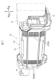
- FIG. 3 is a perspective view of the drive unit with the battery unit removed.
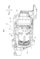
- FIG. 3 is a perspective view of the drive unit with the left housing removed.
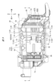
- FIG. 9 is a cross-sectional view (cross-sectional view taken along line 4-4 in FIG. 9) showing the internal structure of the drive unit.
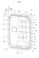
- FIG. 3 is a perspective view of the control unit as seen diagonally from the front.
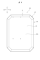
- FIG. 3 is a rear view of the control unit as seen from the rear.
- FIG. 3 is a plan view of the control unit viewed from above.
- FIG. 3 is a left side view of the control unit when viewed from the left.
- FIG. 3 is a left side view of the drive unit from the left with the left housing removed.
- FIG. 3 is a perspective view of the drive unit with the left housing removed, as seen diagonally from the front.
- FIG. 3 is a perspective view of the right housing.
- FIG. 3 is a right side view of the drive unit from the right with the right housing removed.
- FIG. 3 is a perspective view of the drive unit with the right housing removed, as seen diagonally from the front.
- FIG. 3 is a perspective view of the left housing.
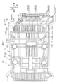
- FIG. 9 is a cross-sectional view (cross-sectional view taken along the line 15-15 in FIG. 9) showing the arrangement of the control unit inside the housing.
- FIG. 9 is a cross-sectional view (cross-sectional view taken along the line 16-16 in FIG. 9) showing the arrangement of the control unit inside the housing.
- FIG. 9 is a cross-sectional view (cross-sectional view taken along the line 16-16 in FIG. 9) showing the arrangement of the control unit inside the housing.
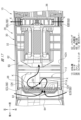
- FIG. 3 is an explanatory diagram showing a state in which airflow flows around the control unit.
- FIG. 2 is a left side view showing a hammer drill as an example of a working machine.
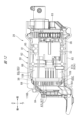
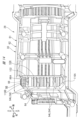
- 19 is a cross-sectional view (cross-sectional view taken along the line 211-211 in FIG. 18) showing the internal structure of the hammer drill.
- FIG. 1 shows a brush cutter 10 as an example of a working machine.
- the brush cutter 10 is used, for example, to cut down grass and small-diameter trees.
- the brush cutter 10 includes a main pipe 12, a handle attachment portion 14, a gear box 22, a rotary blade 24, a grip 26, and a drive unit 28.
- the main pipe 12 is a cylindrical member extending in one direction.
- a drive shaft (not shown) is inserted inside the main pipe 12.
- a handle (not shown) for an operator to grasp can be attached to the handle attachment portion 14 .
- the grip 26 is provided with a lever 27 that is operated by an operator. When the amount of operation of the lever 27 by the operator is changed, the rotation speed of the rotary blade 24 is changed by controlling the operation by a microcomputer 56 (FIG. 5), which will be described later.
- a gearbox 22 is provided at one end of the main pipe 12.
- a rotary blade 24 is attached to the gearbox 22.
- the gearbox 22 transmits a driving force generated in a drive unit 28 (described later) to the rotary blade 24.
- the drive unit 28 is provided at the other end of the main pipe 12.
- the drive unit 28 has a unit main body 30.
- a mounting portion 31 is provided at the rear end portion of the unit main body portion 30 .
- a battery pack 29 is removably provided in the mounting portion 31.
- the battery pack 29 can be attached and detached by moving vertically relative to the mounting part 31. Specifically, the battery pack 29 is attached to the mounting part 31 by moving relative to the mounting part 31 in a downward direction. It is detached from the mounting part 31 by moving upward relative to the part 31.
- the battery pack 29 supplies power to a motor 32 (FIG. 3), which will be described later, when it is attached to the attachment section 31. In other words, the battery pack 29 functions as a power source for the drive unit 28.
- the unit main body 30 includes a motor 32, a fan 36, a control unit 38, a housing 62, and a front cover 112.
- the motor 32, fan 36, and control unit 38 are housed in a space 65 inside the housing 62. Note that the space portion 65 will be described later.
- the motor 32 is a brushless motor.
- the central axis of the motor 32 is designated as a first central axis CA and is represented by a dashed dotted line CA.
- the first central axis CA extends in the front-rear direction.
- the motor 32 has a main body case 33 and a shaft 34.
- the shaft 34 is rotated around the first central axis CA. Further, the shaft 34 extends forward from the main body case 33.
- the driving force of the motor 32 is transmitted to the previously described drive shaft via a transmission section (not shown). That is, the motor 32 rotates the drive shaft via the transmission section.
- the fan 36 is provided at the front end of the shaft 34.
- Fan 36 is a centrifugal fan.
- the central axis of the fan 36 is represented by a dashed line CB.
- the second central axis CB extends in the front-rear direction.
- the second central axis CB and the first central axis CA are aligned in the front-rear direction. That is, the first central axis CA and the second central axis CB are arranged on the same straight line (not shown).
- the fan 36 generates airflow within the space 65 by receiving the driving force of the motor 32 . Airflow generated as the fan 36 rotates flows from a plurality of intake ports 67 (FIG. 4) to a plurality of exhaust ports 68 (FIG. 4), which will be described later.
- control unit 38 includes a case portion 42 and a board portion 51.
- Control unit 38 is an example of a controller.
- the control unit 38 has an octagonal outer shape (a rectangular shape with four corners cut out) when viewed from the front and back directions. Further, the control unit 38 has a flat plate shape with the maximum external size when viewed from the front and rear directions.
- the front-rear direction is an example of the first direction, and corresponds to the thickness direction of the control unit 38.
- the left-right direction is an example of the second direction.
- the vertical direction is an example of the third direction. When viewed from the front and rear directions, the left and right directions and the up and down directions intersect with each other.
- the case portion 42 is formed into a dish shape that opens toward the front.
- the case portion 42 is made of a metal member.
- the case portion 42 may be made of a resin member.
- the length of the case portion 42 in the up-down direction is longer than the length of the case portion 42 in the left-right direction.
- the case part 42 accommodates the board part 51 so that the mounting surface 52A of the board part 51 is exposed to the front.
- the case portion 42 includes a rear wall 43 and a peripheral wall 44 that stands upright from the outer edge of the rear wall 43 forward.
- the rear wall 43 has a flat rear surface 43A (FIG. 6) that extends in the vertical and horizontal directions.
- a tapered surface 47 is formed in a portion from the peripheral edge of the rear surface 43A to the rear end of the peripheral wall 44.
- the peripheral wall 44 is formed into a frame shape having an octagonal outer shape when viewed from the front. Further, the peripheral wall 44 has an octagonal outer peripheral surface 45 when viewed from the front.
- the outer peripheral surface 45 has an upper surface 45A, a slope 45B, a left side 45C, a slope 45D, a lower surface 45E, a slope 45F, a right side 45G, and a slope 45H, which are each flat surfaces.
- the upper surface 45A and the lower surface 45E extend in the left-right direction.
- the left side surface 45C and the right side surface 45G extend in the vertical direction.
- the board section 51 includes, for example, a control board 52, a FET (field effect transistor) 53, a shunt resistor 54, a capacitor 55, a microcomputer 56, and a connector 57. Illustrations and explanations of other mounted components will be omitted.
- the control board 52 has an outer shape in which each of the four corners of a rectangle is cut into an L-shape when viewed from the front and rear directions.
- the control board 52 is housed in the case portion 42 with the thickness direction being in the front-rear direction. Further, the control board 52 is fixed to the case portion 42 with a plurality of screws 59.
- the front surface of the control board 52 is a mounting surface 52A.
- the FET 53, the shunt resistor 54, the capacitor 55, the microcomputer 56, and the connector 57 are mounted on the mounting surface 52A so as to be visible from the front.
- the microcomputer 56 is mounted on the control board 52 on the right side of the center in the left-right direction.
- the area where the microcomputer 56 is mounted and where a circuit pattern (not shown) related to the operation of the microcomputer 56 is formed is defined as a mounting area S1.
- the microcomputer 56 is an example of a control unit that controls the drive of the motor 32 (FIG. 3).
- the microcomputer 56 controls the torque and rotational speed of the motor 32 by adjusting the operating voltage and frequency using an inverter circuit including the FET 53.
- the FET 53, the shunt resistor 54, and the capacitor 55 are mounted on the left side of the center of the control board 52 in the left-right direction.
- the area where the FET 53, the shunt resistor 54, and the capacitor 55 are mounted and where a circuit pattern (not shown) is formed is defined as a mounting area S2.
- a current flows through the motor 32.
- the connector 57 is provided across the lower end of the mounting area S1 and the lower end of the mounting area S2.
- the mounting areas S1 and S2 are covered from the front with resin R (FIG. 4).
- the resin R is filled inside the case portion 42 and is cured.
- An example of the resin R is a curable resin such as urethane. Note that illustration of the resin R is omitted in figures other than FIGS. 4 and 17.
- the amount of current used to drive the motor 32 is larger than the amount of current used to control the drive of the motor 32. That is, when the motor 32 is operating, the total amount of current flowing in the mounting area S2 is larger than the total amount of current flowing in the mounting area S1. Therefore, the amount of heat generated in the mounting area S2 is greater than the amount of heat generated in the mounting area S1.
- the amount of heat generated in the mounting area S2 exceeds the allowable amount, the operation of each element including the FET 53 may become unstable. In other words, if the amount of heat generated in the mounting area S2 is large, the operation of the motor 32 may become unstable. Therefore, when the ability to cool the mounting area S2 is higher than the ability to cool the mounting area S1, the operation of the motor 32 is more likely to be stabilized.
- the microcomputer 56 is used as an example of a control unit and an example of a first element. Further, the FET 53 is used as an example of the second element. That is, the control unit 38 includes the microcomputer 56 and the FET 53, which generates a larger amount of heat during operation than the microcomputer 56. Note that at least one of the shunt resistor 54 and the capacitor 55 may be used as an example of the second element.
- the housing 62 is formed in a box shape extending in the front-rear direction when viewed from the left and right directions.
- a power transmission section 63 that accommodates a drive shaft (not shown) is provided at the front end of the housing 62.
- the mounting portion 31 is provided with a connector (not shown).
- the housing 62 houses the motor 32, control unit 38, and fan 36 therein. Additionally, housing 62 has an opening 66 .
- a reference line A is an imaginary line that passes through approximately the center of the housing 62 in the front-back direction and extends in the left-right direction.
- the housing 62 is divided into left and right parts, as will be described later.
- a virtual plane passing through the center of the housing 62 in the left-right direction and extending in the vertical direction is defined as a dividing plane D.
- the dividing plane D is represented by a dashed line D.
- the opening 66 has a plurality of intake ports 67 and a plurality of exhaust ports 68.
- the plurality of intake ports 67 are located behind the reference line A and in front of the mounting portion 31. Further, the plurality of intake ports 67 are arranged at intervals in the vertical direction on the right side and the left side of the dividing surface D, respectively. Furthermore, the plurality of intake ports 67 are located on the rear side of the control unit 38. The rear side in the front-rear direction is an example of one side in the first direction.
- the plurality of exhaust ports 68 are located ahead of the reference line A and behind the power transmission section 63. Further, the plurality of exhaust ports 68 are arranged at intervals in the vertical direction on the right side and the left side of the dividing surface D, respectively. Furthermore, the plurality of exhaust ports 68 are located in front of the control unit 38. In other words, the control unit 38 is arranged between the plurality of exhaust ports 68 that are part of the opening 66 and the fan 36 in the front-rear direction. Note that the front side in the front-back direction is an example of the other side in the first direction.
- the intake port 67 and the exhaust port 68 are, for example, each formed in a rectangular shape extending in the front-rear direction, and communicate the inside and outside of the housing 62.
- air which is an example of gas
- air flowing into the housing 62 from the intake port 67 flows forward inside the housing 62 and flows out from the exhaust port 68 to the outside.
- the housing 62 is divided into a right side and a left side of the dividing plane D. That is, the housing 62 includes a right housing 71 and a left housing 81.
- the right housing 71 is an example of a first housing.
- the left housing 81 is an example of a second housing. Note that the right side is an example of one side in the second direction. The left side is an example of the other side in the second direction.
- the intake port 67 provided in the right housing 71 is referred to as an intake port 67R. Furthermore, the exhaust port 68 provided in the right housing 71 is referred to as an exhaust port 68R.
- the intake port 67 provided in the left housing 81 is referred to as an intake port 67L. Furthermore, the exhaust port 68 provided in the left housing 81 is referred to as an exhaust port 68L.
- the housing 62 is provided with a plurality of intake ports 67R, 67L and a plurality of exhaust ports 68R, 68L.
- the right housing 71 has a bottom wall 72, a front wall 73, a vertical wall 74, a right side wall 75, and a top wall 76.
- the bottom wall 72 is formed into a plate shape having a predetermined thickness in the vertical direction.
- the front wall 73 stands upright upward from the front end of the bottom wall 72.
- the vertical wall 74 stands upright from the rear end of the bottom wall 72.
- the right side wall 75 stands upright from the right end of the bottom wall 72.
- the upper wall 76 extends from the upper ends of the front wall 73, the vertical wall 74, and the right side wall 75 in the left-right direction and the front-rear direction.
- a portion surrounded by the bottom wall 72, front wall 73, vertical wall 74, right side wall 75, and top wall 76 is defined as a right space portion 65R.
- the right housing 71 has a joint surface 78 that is the left end surface of the right housing 71.
- the inner surface of the right housing 71 is an inner wall surface 71A.
- the inner wall surface 71A is an example of the inner wall of the first housing.
- the left housing 81 has a bottom wall 82, a front wall 83, a vertical wall 84, a left side wall 85, and a top wall 86.
- the bottom wall 82 is formed into a plate shape having a predetermined thickness in the vertical direction.
- the front wall 83 stands upright upward from the front end of the bottom wall 82.
- the vertical wall 84 stands upright from the rear end of the bottom wall 82 .
- the left side wall 85 stands upright upward from the left end of the bottom wall 82.
- the upper wall 86 extends from the upper ends of the front wall 83, the vertical wall 84, and the left side wall 85 in the left-right direction and the front-rear direction.
- a portion surrounded by the bottom wall 82, the front wall 83, the vertical wall 84, the left side wall 85, and the top wall 86 is defined as a left space portion 65L.
- the left housing 81 has a joint surface 88 that is the right end surface of the left housing 81.
- the inner surface of the left housing 81 is defined as an inner wall surface 81A.
- the inner wall surface 81A is an example of the inner wall of the second housing.
- the inner wall surface 71A (FIG. 9) and the inner wall surface 81A are combined to form an inner wall surface 62A.
- the inner wall surface 62A is an example of the inner wall of the housing 62.
- the space 65 has a right space 65R and a left space 65L. Note that the joining surfaces 78 and 88 are included in the dividing surface D.
- a rear wall 79 is provided behind the vertical wall 74.
- a rear wall 89 is provided behind the vertical wall 84.
- the space 65 includes a fan housing chamber 65A that houses the fan 36, a motor housing chamber 65B that houses the motor 32, and a controller housing chamber 65C that houses the control unit 38.
- the fan storage chamber 65A is located at the rear of the front wall 73 (FIG. 9) and the front wall 83 (FIG. 12).
- the motor housing chamber 65B is located at the rear of the fan housing chamber 65A.
- the controller housing chamber 65C is located at the rear of the motor housing chamber 65B. Note that in the left housing 81, no wall is provided between the motor housing chamber 65B and the controller housing chamber 65C. In other words, in the left housing 81, a flow section 77 through which gas can flow is formed between the motor housing chamber 65B and the controller housing chamber 65C.
- a front cover 112 which will be described later, is provided between the motor housing chamber 65B and the controller housing chamber 65C in the front-rear direction.
- a flow path portion 92 is provided between the control unit 38 and the vertical walls 74, 84 in the front-rear direction.
- the flow path section 92 includes a vertical wall 74, a vertical wall 84, and a plurality of flow path forming plates 94.
- the flow path forming plate 94 has a predetermined thickness in the vertical direction.
- a plurality of flow path forming plates 94 are arranged at intervals in the vertical direction.
- the flow path forming plate 94 is formed by aligning a right plate portion 94A located on the right side of the dividing surface D and a left plate portion 94B located on the left side of the dividing surface D in the left-right direction.
- the right plate portion 94A extends forward from the vertical wall 74 and extends to the peripheral edge of the intake port 67R.
- the left plate portion 94B extends forward from the vertical wall 84 and extends to the peripheral edge of the intake port 67L. In this way, gas can flow in the flow path section 92, and the gas taken in from the plurality of intake ports 67R and 67L flows to the control unit 38.
- a notch 96 and a unit support portion 98 are formed at the front end of the flow path forming plate 94.
- the notch 96 is cut out from the center of the front end of the flow path forming plate 94 in the left-right direction so as to be depressed toward the rear.
- the cutout portion 96 is cut out in a V-shape when viewed from the top and bottom. In other words, the notch 96 is cut out so that the closer it is to the center in the left-right direction, the further away from the control unit 38 it is.
- the plurality of notches 96 are arranged in the vertical direction, allowing airflow to flow in the vertical direction.
- the cutout portion 96 is an example of a through hole, and is capable of penetrating the flow path portion 92 in the vertical direction and allowing ventilation. Note that in this embodiment, the notch 96 is included in the through hole.
- the unit support portions 98 are formed on the right and left sides of the notch 96 at the front end of the flow path forming plate 94. As shown in FIGS. The unit support portion 98 has a support surface 98A that faces the rear surface 43A and the tapered surface 47 (FIG. 6). The support surface 98A is formed to match the shape of the rear surface 43A and the tapered surface 47. The unit support portion 98 supports the control unit 38 from the rear because the support surface 98A contacts at least one of the rear surface 43A and the tapered surface 47.
- a partition wall 102 is provided at a position in front of the unit support portion 98 and at a position outside the control unit 38 (FIG. 4) in the left-right direction.
- the partition wall 102 extends from the inner wall surface 62A toward the center in the left-right direction, and is formed in a plate shape with a thickness direction in the front-rear direction.
- the partition wall 102 extends in the vertical direction.
- the height of the partition wall 102 in the vertical direction is approximately the same as the height of the control unit 38 in the vertical direction.
- the upper and lower ends of the partition wall 102 can come into contact with the left side surface 45C and right side surface 45G of the control unit 38.
- the control unit 38 can be supported by the unit support portion 98 (FIG. 11) and the bulkhead 102.
- the housing 62 can support both ends of the control unit 38 in the left and right direction.
- a portion of the partition wall 102 that is lined up with the control unit 38 in the left-right direction and excluding the top and bottom ends of the partition wall 102 is recessed toward the side away from the control unit 38 . That is, a slit-shaped gap 104 is formed between a part of the partition wall 102 and the control unit 38.
- the gap portion 104 is formed in a rectangular shape extending in the vertical direction when viewed from the front and rear directions. Furthermore, the gap portion 104 has a size that allows gas to flow in the front-rear direction. Furthermore, the gap portion 104 is located on both sides of the control unit 38 in the left-right direction.
- the amount of gas flowing through the gap 104 is smaller than the amount of gas flowing through ventilation paths 106 and 107, which will be described later. In other words, most of the gas flows through the ventilation paths 106 and 107, and the remaining gas flows through the gap 104.
- the right housing 71 is provided with ventilation passages 106 and 107.
- the ventilation passages 106 and 107 are located on both sides of the control unit 38 in the vertical direction when the control unit 38 is attached to the housing 62.
- the ventilation path 106 is located above a portion corresponding to the mounting area S1 (FIG. 5) of the control unit 38, and allows gas to flow in the front-rear direction.
- the ventilation path 107 is located below a portion corresponding to the mounting area S1 of the control unit 38, and gas can flow in the front-rear direction.
- the ventilation passages 106 and 107 are not provided in the left housing 81.
- the left housing 81 is provided with restriction walls 108 and 109.
- the limiting walls 108 and 109 are located on both sides of the control unit 38 in the vertical direction when the control unit 38 is attached to the housing 62.
- the restriction walls 108 and 109 each have a plate-shaped portion that extends in the left-right direction and the up-down direction. Further, the restriction walls 108 and 109 are each bent in a crank shape when viewed from the left and right directions.
- the restriction wall 108 is located above a portion corresponding to the mounting area S2 (FIG. 5) of the control unit 38, and restricts the flow of gas in the front-rear direction. Further, the lower end of the restriction wall 108 is in contact with the upper end of the peripheral wall 44 from the front.
- the restriction wall 109 is located below a portion corresponding to the mounting area S2 of the control unit 38, and restricts the flow of gas in the front-rear direction. Further, the upper end of the restriction wall 109 is in contact with the lower end of the peripheral wall 44 from the front. Note that the limiting walls 108 and 109 are not provided in the right housing 71 (FIG. 9).
- the restriction wall 108 is aligned with the ventilation path 106 in the left-right direction, and is located on the left side of the ventilation path 106.
- the restriction wall 109 is aligned with the ventilation path 107 in the left-right direction and is located on the left side of the ventilation path 107.
- the restricting walls 108 and 109 that restrict the airflow are provided on the left side of the ventilation passages 106 and 107 in the left-right direction on the inside of the housing 62.
- the lower end portion of the restriction wall 108 and the upper end portion of the restriction wall 109 function as a restriction portion that restricts the control unit 38 from tilting forward.
- the front cover 112 is erected from the inner wall surface 71A of the right housing 71 toward the right side in the left-right direction (left housing 81 side).
- the front cover 112 is an example of a wall.
- the front cover 112 is erected so as to overlap the right side of the dividing surface D of the control unit 38 when viewed in the front-rear direction from the front to the rear.
- the front cover 112 is located on the right side as the other side in the left-right direction when viewed from the front-rear direction.
- a left end surface 113 is formed at the left end of the front cover 112.
- the left end surface 113 is an example of the tip of the wall.
- the left end surface 113 is formed into a planar shape located on the dividing plane D. In this way, the front cover 112 is provided only inside the right housing 71 and not inside the left housing 81 (FIG. 12).
- the front cover 112 has a bottom wall 112A, an inclined wall 112B, a front wall 112C, an inclined wall 112D, and an upper wall 112E.
- the bottom wall 112A is located below the control unit 38 and extends further forward than the control unit 38.
- the inclined wall 112B extends diagonally upward from the front end of the bottom wall 112A.
- the front wall 112C extends upward in the vertical direction from the upper end of the inclined wall 112B.
- the inclined wall 112D extends diagonally rearward from the upper end of the front wall 112C.
- the upper wall 112E extends rearward from the upper end of the inclined wall 112D.
- the upper wall 112E is located above the control unit 38.
- the front cover 112 overlaps the fan 36 when viewed in the front-rear direction from the front to the rear. Specifically, when the fan 36 is projected onto the front cover 112 along the front-rear direction, the right side portion of the fan 36 with respect to the dividing plane D overlaps with the front cover 112. When viewed in the front-rear direction, a portion of the fan 36 on the left side of the dividing plane D does not overlap with the front cover 112 but overlaps with the control unit 38.
- the FET 53, the shunt resistor 54, and the capacitor 55 When viewed in the front-rear direction from the front to the rear, a portion of the FET 53, the shunt resistor 54, and the capacitor 55 are located between the left end surface 113 and the inner wall surface 81A. In other words, some of the FET 53, the shunt resistor 54, and the capacitor 55 are not covered by the front cover 112 when viewed in the front-rear direction. Therefore, after cooling the FET 53, the shunt resistor 54, and the capacitor 55, the airflow is not restricted by the front cover 112 and can flow forward through the flow section 77.
- the controller storage chamber 65C is provided with slopes 114A and 114B.
- the slope 114A extends diagonally downward from the lower end of the vertical wall 74 toward the bottom wall 112A.
- the slope 114B extends obliquely upward from the upper end of the vertical wall 74 toward the upper wall 112E.
- the gas that has flowed into the controller storage chamber 65C from the plurality of intake ports 67R is guided by the slopes 114A and 114B so as to flow into the ventilation paths 106 and 107.
- the controller housing chamber 65C is formed in an octagonal shape when viewed in the left-right direction from the left side to the right side.
- the controller housing chamber 65C is provided with slopes 116A and 116B.
- the slope 116A extends diagonally downward from the lower end of the vertical wall 84 toward a position below the control unit 38.
- the slope 116B extends obliquely upward from the upper end of the vertical wall 84 toward a position above the control unit 38.
- the left housing 81 is provided with restriction walls 108 and 109. Therefore, the gas that has flowed into the controller storage chamber 65C from the plurality of intake ports 67L is restricted from flowing forward from the slopes 116A and 116B.
- the airflow flowing through the space behind the control unit 38 and facing the upper part of the control unit 38 is defined as an airflow K1. Further, the airflow flowing through the space behind the control unit 38 and facing the lower part of the control unit 38 is defined as an airflow K2. Since the forward flow of the airflow K1 is restricted by the control unit 38 and the restriction wall 108, the airflow K1 flows toward the open air passage 106. Then, the airflow K1 passes forward over the control unit 38 by passing through the ventilation path 106, and then begins to flow downward and forward. Since the forward flow of the airflow K2 is restricted by the control unit 38 and the restriction wall 109, the airflow K2 flows toward the open air passage 107. Then, the airflow K2 passes forward through the control unit 38 by passing through the ventilation path 107, and then begins to flow upward and forward. A portion of the airflow K1 and a portion of the airflow K2 merge to form an airflow K.
- the airflow K that has passed the control unit 38 tends to flow further forward.
- the airflow K is restricted from moving forward by colliding with the front cover 112 , and is guided by the front cover 112 to flow toward the left side of the control unit 38 .
- the airflow K flows toward the front of the left side portion of the control unit 38 because its traveling direction is turned around at the front cover 112 .
- the airflow K flows in front of the left side portion of the control unit 38 and collides with the base plate portion 51, so that the direction of movement of the airflow K is turned back toward the front.
- the airflow K flows through the FET 53, the shunt resistor 54, and the capacitor 55. This cools the FET 53, the shunt resistor 54, and the capacitor 55.
- the airflow K passes through the plurality of exhaust ports 68 and is exhausted to the outside of the housing 62.
- gap portions 104 are provided on both sides of the control unit 38 in the left-right direction. Therefore, a part of the airflow K flowing through the flow path section 92 flows forward through the gap section 104, thereby cooling the left side surface 45C and the right side surface 45G, so that both ends of the case section 42 in the left and right direction can also be cooled.
- the airflow K that has collided with the front cover 112 is changed in direction so as to turn back, and thus flows toward the control unit 38.
- the airflow K is guided by the front cover 112 and flows into the mounting area S2.
- the airflow K cools the FET 53, the shunt resistor 54, and the capacitor 55. In this way, not only the rear part but also the front part of the control unit 38 is cooled, so that in addition to the microcomputer 56, a rise in temperature of the FET 53, the shunt resistor 54, and the capacitor 55 in particular can be suppressed.
- the ventilation paths 106 and 107 that allow ventilation to the control unit 38, and the upper and lower ends of the partition wall 102 that supports the control unit 38 are arranged separately in the horizontal direction and the vertical direction. has been done. This increases the flow area of the ventilation passages 106 and 107 and makes it easier to prevent the control unit 38 from tilting, compared to a case where the ventilation part and the part supporting the control unit 38 are combined in the same part. be able to.
- the restriction walls 108, 109 restrict the airflow K on the left side of the air passages 106, 107. Thereby, the airflow K comes to flow to the right side of the ventilation paths 106 and 107.
- the airflow K that has passed over the control unit 38 collides with the front cover 112 and is guided toward the left side of the control unit 38 (mounting area S2).
- the airflow K flowing through the ventilation passages 106 and 107 is more likely to flow toward the front cover 112 and easily be folded back, so that the control unit 38 can be easily cooled.
- the airflow K generated by the rotation of the fan 36 flows from the plurality of intake ports 67, beyond the control unit 38, to the plurality of exhaust ports 68.
- the plurality of intake ports 67 are provided on both sides of the housing 62 in the left-right direction, air intake becomes easier than in a configuration in which the intake ports 67 are provided only on one side in the left-right direction.
- the flow path section 92 guides the airflow K toward the control unit 38, more airflow K can flow toward the rear surface 43A of the control unit 38.
- a part of the airflow K guided by the flow path section 92 flows in the vertical direction through the notch section 96.
- the airflow K flowing in the vertical direction passes over the control unit 38 in the front-back direction after reaching the upper and lower ends of the control unit 38. This makes it difficult for a part of the airflow K to stay in each flow path section 92, so that the airflow K can easily cross the control unit 38 in the front-rear direction.
- the space in which the fan 36 and the front cover 112 are provided can be made smaller in the left-right direction or the vertical direction. can be downsized.
- the space in which the motor 32 and the fan 36 are provided can be made smaller in the left-right direction or the up-down direction.
- the brush cutter 10 can be downsized.
- the front cover 112 is provided only on the right housing 71. Therefore, the front cover 112 and the right housing 71 can be integrally molded. Thereby, the number of man-hours for manufacturing the brush cutter 10 can be reduced compared to a configuration in which the front cover 112 and the right housing 71 are separate bodies.
- the airflow K is guided by the front cover 112 and flows toward the left end surface 113 of the front cover 112, and also flows toward the mounting area S2 of the control unit 38.
- the FET 53 is located between the left end surface 113 and the inner wall surface 81A when viewed in the front-rear direction from the front to the rear. In other words, the FET 53 is located on the path of the airflow K. Thereby, the FET 53, which generates a large amount of heat, can be easily cooled by the airflow K.
- the present invention is not limited to the above-described embodiment, and can be modified in various ways without departing from the gist thereof.
- the motor 32 rotates the rotary blade 24 as a tool, but the motor 32 is not limited to driving a tool.
- the fan 36 is not limited to a centrifugal fan, but may be an axial fan. When the fan 36 is an axial fan, the fan 36 may be placed behind the control unit 38 and blow air toward the rear surface 43A of the control unit 38. In the brush cutter 10, the arrangement of the members may be reversed laterally with respect to the dividing plane D.
- Each member may be arranged with the up-down direction as an example of the second direction and the left-right direction as an example of the third direction.
- the case portion 42 is not limited to a flat aggregate, but may have a partially curved surface.
- the housing 62 is not limited to a structure in which it is divided into two parts, but may be in a structure in which it is divided into three or more parts.
- the front cover 112 is not limited to a flat aggregate, but may have a partially curved surface.
- the flow path forming plate 94 may be formed with a through hole that vertically penetrates the flow path forming plate 94. The number of the through holes may be singular or plural.
- the front cover 112 may extend beyond the dividing plane D to the left side. In this configuration, the limiting walls 108, 109 may not be provided.
- the flow path section 92 does not need to be provided in the housing 62.
- the plurality of flow path forming plates 94 may not be provided.
- the cutout portion 96 may not be provided.
- the fan 36 and the front cover 112 do not need to overlap when viewed from the front and rear directions.
- the first central axis CA and the second central axis CB do not need to be aligned in the front-rear direction.
- the front cover 112 When viewed from the vertical direction, the front cover 112 may be erected from the inner wall surface 71A toward the control unit 38 in a cross direction that intersects the left-right direction. Further, the front cover 112 is not limited to a flat plate shape, and may be entirely curved or partially curved. Parts of each of the FET 53, the shunt resistor 54, and the capacitor 55 may be arranged so as to overlap the front cover 112 when viewed in the front-rear direction.
- a hammer drill 200 as a second embodiment of the present invention is shown in FIGS. 18 and 19.
- the hammer drill 200 has a motor 202 including a rotor 202A, a stator 202B, and a drive shaft 202C inside a housing 201, and operates a tip tool 210 by a mechanism section 204 that operates in response to the driving force of the motor 202. Performs drilling work and crushing work on mating materials such as concrete.
- the mechanism unit 204 uses a driving force of the motor 202 to apply a striking force to the tip tool in the longitudinal direction (back-and-forth direction) and rotate the tip tool about an axis extending in the longitudinal direction (back-and-forth direction). It can give rotational force and.
- the housing 201 is provided with a switching operation section (not shown) that switches the mode of the mechanism section 204.
- a switching operation section (not shown) that switches the mode of the mechanism section 204.
- the mode of the mechanism section 204 is set to hammer mode by the switching operation section, only impact force is applied to the tip tool, and the mechanism section 204
- the mode of the mechanism section 204 is set to the hammer drill mode, impact force and rotational force are applied to the tip tool, and when the mode of the mechanism section 204 is set to the drill mode, only rotational force is applied to the tip tool.
- a control unit 205 that controls driving of the motor 202 is housed inside the housing 201 .
- the control unit 205 includes a control board 205A, an FET 205B (an example of a switching element) mounted on the control board 205A, and a case portion 205C that houses the control board 205A therein.
- the case portion 205C is made of metal, covers the rear surface, upper, lower, left and right surfaces of the control board 205A, and has a box shape with an open front surface.
- the control unit 205 has a flat plate shape whose outer diameter is maximum when viewed from the front (first direction).
- An intake port 201B is provided in the housing 201.
- a fan 203 is attached to the drive shaft 202C of the motor 202. Since the fan 203 is located in front of the control unit 205 and the intake port 201B is located in the rear of the control unit 205, the control unit 205 is disposed between the intake port 201B and the fan 203 in the front-rear direction.
- a space on the rear side and a space on the front side of the control unit 205 are partitioned into front and back by a restriction wall 206, and an intake port 201B is connected to the space on the rear side. The position of the restriction wall 206 in the front-rear direction overlaps with the control unit 205.
- the restriction wall 206 is provided with a ventilation passage 207 arranged adjacent to the control unit 205 in the left-right direction.
- the ventilation passage 207 may be disposed on at least one of the left and right sides of the control unit 205, but in this embodiment, it is disposed on both the left and right sides.
- the front cover 208 is arranged so as to overlap the control unit 205 when viewed in the front-rear direction, and is arranged between the control unit 205 and the fan 203 in the front-rear direction.
- the front cover 208 is provided with a flow section 209 that is arranged below the ventilation path 207 and communicates the space that the control unit 205 faces and the space where the motor 202 is provided.
- the airflow K generated by the fan 203 and flowing around the control unit 205 when the motor 202 is driven will be described.
- the airflow K entering the housing 201 from the intake port 201B flows upward while moving away from the center of the control unit 205 in the left-right direction along the rear surface of the case portion 205C.
- the airflow K cools the case portion 205C and indirectly cools the control board 205A and FET 205B.
- the airflow K passes through a ventilation path 207 provided in the restriction wall 206 and enters from the space behind the restriction wall 206 to the space in front of the restriction wall 206 .
- the airflow K changes its course toward the center of the control unit 205 in the left-right direction.
- the airflow K collides with the front cover 208, thereby changing its course downward and rearward.
- the front cover 208 directs the airflow K downward where the circulation section 209 is located.
- the airflow K collides with the control board 205A, particularly around the FET 205B, and cools them.
- the airflow K passes through the circulation portion 209, flows forward of the front cover 208, passes around the motor 202, flows upward toward the fan 203, and then flows out of the housing 201 from the exhaust port 201C.
- control unit 205 especially the FET 205B, is effectively cooled, so that the workability of the work machine can be improved.
- the working machines to which the present invention is applied are not limited to brush cutters and hammer drills, but can be applied to various working machines having motors, controllers, and fans.
- Ventilation path 107... Ventilation path, 108... Restriction wall, 109... Restriction wall, 112... Front cover (example of wall part), 113... Left end surface (example of tip), CA... No. 1 center axis, CB...second center axis, 201...housing, 201A...handle, 201B...intake port, 201C...exhaust port, 202...motor, 202A...rotor, 202B...stator, 202C...drive shaft, 203...fan, 204... Mechanism part, 205... Control unit, 205A... Control board, 205B... FET, 205C... Case part, 206... Restriction wall, 207... Ventilation path, 208... Front cover, 209... Distribution part, 210... Tip tool
Landscapes
- Life Sciences & Earth Sciences (AREA)
- Environmental Sciences (AREA)
- Engineering & Computer Science (AREA)
- Mechanical Engineering (AREA)
- Cooling Or The Like Of Electrical Apparatus (AREA)
- Harvester Elements (AREA)
Priority Applications (4)
| Application Number | Priority Date | Filing Date | Title |
|---|---|---|---|
| CN202380060123.1A CN119730993A (zh) | 2022-08-19 | 2023-08-10 | 作业机 |
| JP2024541533A JPWO2024038822A1 (https=) | 2022-08-19 | 2023-08-10 | |
| US19/104,802 US20260054365A1 (en) | 2022-08-19 | 2023-08-10 | Working machine |
| DE112023003503.2T DE112023003503T5 (de) | 2022-08-19 | 2023-08-10 | Arbeitsmaschine |
Applications Claiming Priority (2)
| Application Number | Priority Date | Filing Date | Title |
|---|---|---|---|
| JP2022130926 | 2022-08-19 | ||
| JP2022-130926 | 2022-08-19 |
Publications (1)
| Publication Number | Publication Date |
|---|---|
| WO2024038822A1 true WO2024038822A1 (ja) | 2024-02-22 |
Family
ID=89941608
Family Applications (1)
| Application Number | Title | Priority Date | Filing Date |
|---|---|---|---|
| PCT/JP2023/029231 Ceased WO2024038822A1 (ja) | 2022-08-19 | 2023-08-10 | 作業機 |
Country Status (5)
| Country | Link |
|---|---|
| US (1) | US20260054365A1 (https=) |
| JP (1) | JPWO2024038822A1 (https=) |
| CN (1) | CN119730993A (https=) |
| DE (1) | DE112023003503T5 (https=) |
| WO (1) | WO2024038822A1 (https=) |
Citations (6)
| Publication number | Priority date | Publication date | Assignee | Title |
|---|---|---|---|---|
| JP2011230229A (ja) * | 2010-04-27 | 2011-11-17 | Hitachi Koki Co Ltd | 電動工具 |
| JP2017094453A (ja) * | 2015-11-25 | 2017-06-01 | パナソニックIpマネジメント株式会社 | 電動工具 |
| JP2018062053A (ja) * | 2016-10-07 | 2018-04-19 | 株式会社マキタ | 電動工具 |
| JP2020163780A (ja) * | 2019-03-29 | 2020-10-08 | 工機ホールディングス株式会社 | 切断機 |
| JP2020175494A (ja) * | 2019-04-22 | 2020-10-29 | 株式会社マキタ | 作業工具 |
| JP2021133477A (ja) * | 2020-02-28 | 2021-09-13 | 工機ホールディングス株式会社 | 動力工具 |
Family Cites Families (33)
| Publication number | Priority date | Publication date | Assignee | Title |
|---|---|---|---|---|
| US3343613A (en) * | 1966-08-01 | 1967-09-26 | New Draulics Inc | Power operated tool |
| US3878809A (en) * | 1974-02-14 | 1975-04-22 | Morton Ray | Air-cooled electric outboard motor |
| US4286675A (en) * | 1979-06-25 | 1981-09-01 | Beaird-Poulan Division Of Emerson Electric Co. | Narrow profile power handle for line trimmer and the like |
| DE4239559C2 (de) * | 1992-11-25 | 2000-12-21 | Festo Ag & Co | Handwerkzeugmaschine mit einer Blockiereinrichtung zum Blockieren der Werkzeugspindel beim Werkzeugwechsel |
| US5802724A (en) * | 1994-09-09 | 1998-09-08 | Ryobi North America | Coupling for split-boom power tool |
| FR2729213B1 (fr) * | 1995-01-11 | 1997-03-14 | Cuenod Thermotech Sa | Bruleur a air souffle |
| US6006434A (en) * | 1997-09-30 | 1999-12-28 | Hoffco, Inc. | Quick-release component connector for lawn tool |
| DE19839963A1 (de) * | 1998-09-02 | 2000-03-09 | Hilti Ag | Elektrowerkzeug |
| JP4075540B2 (ja) * | 2002-09-10 | 2008-04-16 | 松下電工株式会社 | 電動工具 |
| US7004357B2 (en) * | 2003-05-15 | 2006-02-28 | Alemite, Llc | Grease gun |
| JP4639061B2 (ja) * | 2004-07-29 | 2011-02-23 | 株式会社マキタ | 電動工具 |
| US20060123635A1 (en) * | 2004-12-09 | 2006-06-15 | Heow, Inc. | Combination blower, trimmer and edger for tending vegetation |
| US8020304B2 (en) * | 2008-02-13 | 2011-09-20 | Echo, Incorporated | Power transmission assembly for tool mounted on an elongate pole |
| CN101543967B (zh) * | 2008-03-28 | 2011-12-28 | 德昌电机(深圳)有限公司 | 带冷却系统的电钻 |
| DE102010030059A1 (de) * | 2010-06-15 | 2011-12-15 | Hilti Aktiengesellschaft | Handgeführtes Eintreibgerät |
| TWI572458B (zh) * | 2011-11-02 | 2017-03-01 | Max Co Ltd | electrical tools |
| JP2013166209A (ja) * | 2012-02-15 | 2013-08-29 | Makita Corp | 打撃工具 |
| US9467030B2 (en) * | 2013-03-15 | 2016-10-11 | Regal Beloit Australia Pty Ltd | Air-cooled electric machine and method of assembling the same |
| WO2015093057A1 (en) * | 2013-12-20 | 2015-06-25 | Hitachi Koki Co., Ltd. | Power-actuated tool |
| JP5777024B2 (ja) * | 2014-04-28 | 2015-09-09 | 日立工機株式会社 | 電動工具 |
| JP2016124049A (ja) * | 2014-12-26 | 2016-07-11 | 日立工機株式会社 | 電動工具および制御基板の製造方法 |
| AU2016200049B2 (en) * | 2015-01-06 | 2020-01-02 | Techtronic Industries Co., Ltd. | Axial blower vacuum |
| JP6655958B2 (ja) * | 2015-01-29 | 2020-03-04 | 株式会社マキタ | ハンマドリル又は電動ハンマ、電動工具 |
| JP6656600B2 (ja) * | 2016-04-28 | 2020-03-04 | 工機ホールディングス株式会社 | 電動工具 |
| CN109328123B (zh) * | 2016-06-30 | 2022-04-29 | 工机控股株式会社 | 电动工具 |
| US10493577B2 (en) * | 2016-07-21 | 2019-12-03 | Makita Corporation | Dust collection device for electric power tool, electric power tool, and dust collection system |
| JP7236956B2 (ja) * | 2019-08-08 | 2023-03-10 | 株式会社マキタ | 電動工具及び往復動切断工具 |
| WO2021107827A1 (en) * | 2019-11-25 | 2021-06-03 | Husqvarna Ab | A hand-held electrically powered work tool |
| JP7667667B2 (ja) * | 2021-03-09 | 2025-04-23 | 株式会社マキタ | 作業機 |
| JP7588017B2 (ja) * | 2021-03-26 | 2024-11-21 | 株式会社マキタ | 往復動切断工具 |
| CA3223635A1 (en) * | 2021-06-22 | 2022-12-29 | Shouchuan FENG | Blade assembly, power head and lawn mower |
| JP7759265B2 (ja) * | 2022-01-20 | 2025-10-23 | 株式会社やまびこ | 動力作業機 |
| US12368347B2 (en) * | 2022-12-01 | 2025-07-22 | Norbar Torque Tools Limited | Cooling electronics of power tools |
-
2023
- 2023-08-10 JP JP2024541533A patent/JPWO2024038822A1/ja active Pending
- 2023-08-10 DE DE112023003503.2T patent/DE112023003503T5/de active Pending
- 2023-08-10 US US19/104,802 patent/US20260054365A1/en active Pending
- 2023-08-10 WO PCT/JP2023/029231 patent/WO2024038822A1/ja not_active Ceased
- 2023-08-10 CN CN202380060123.1A patent/CN119730993A/zh active Pending
Patent Citations (6)
| Publication number | Priority date | Publication date | Assignee | Title |
|---|---|---|---|---|
| JP2011230229A (ja) * | 2010-04-27 | 2011-11-17 | Hitachi Koki Co Ltd | 電動工具 |
| JP2017094453A (ja) * | 2015-11-25 | 2017-06-01 | パナソニックIpマネジメント株式会社 | 電動工具 |
| JP2018062053A (ja) * | 2016-10-07 | 2018-04-19 | 株式会社マキタ | 電動工具 |
| JP2020163780A (ja) * | 2019-03-29 | 2020-10-08 | 工機ホールディングス株式会社 | 切断機 |
| JP2020175494A (ja) * | 2019-04-22 | 2020-10-29 | 株式会社マキタ | 作業工具 |
| JP2021133477A (ja) * | 2020-02-28 | 2021-09-13 | 工機ホールディングス株式会社 | 動力工具 |
Also Published As
| Publication number | Publication date |
|---|---|
| JPWO2024038822A1 (https=) | 2024-02-22 |
| US20260054365A1 (en) | 2026-02-26 |
| DE112023003503T5 (de) | 2025-07-10 |
| CN119730993A (zh) | 2025-03-28 |
Similar Documents
| Publication | Publication Date | Title |
|---|---|---|
| JP7667667B2 (ja) | 作業機 | |
| JP7348748B2 (ja) | ブロワ | |
| JP6461683B2 (ja) | 電動作業車両 | |
| JP5333719B2 (ja) | 電動工具 | |
| US20080106159A1 (en) | Portable power working machine | |
| EP2908984B1 (en) | Outdoor power device internal cooling system | |
| JP2016199135A (ja) | 電動作業車両 | |
| EP4129730B1 (en) | Electric construction machine | |
| JP2009214292A (ja) | 切断機 | |
| CN116657691A (zh) | 作业机械 | |
| JP2009067003A (ja) | 電動カッタ | |
| WO2024038822A1 (ja) | 作業機 | |
| JP7441736B2 (ja) | 電動作業機 | |
| EP4215324B1 (en) | Power working machine | |
| WO2018180084A1 (ja) | 電動工具 | |
| JP2021197775A (ja) | 電動作業機及び電動作業機の製造方法 | |
| JP7540499B2 (ja) | 作業機 | |
| JP7321754B2 (ja) | 携帯用切断機 | |
| US12415223B2 (en) | Cut-off saw | |
| JP2021194768A (ja) | 作業機 | |
| JP2024017590A (ja) | 作業機 | |
| JP7824522B2 (ja) | 作業機 | |
| JP2025181534A (ja) | 作業機 | |
| JP2024024260A (ja) | 作業機 | |
| JP7409051B2 (ja) | 電気機器 |
Legal Events
| Date | Code | Title | Description |
|---|---|---|---|
| 121 | Ep: the epo has been informed by wipo that ep was designated in this application |
Ref document number: 23854856 Country of ref document: EP Kind code of ref document: A1 |
|
| WWE | Wipo information: entry into national phase |
Ref document number: 2024541533 Country of ref document: JP |
|
| WWE | Wipo information: entry into national phase |
Ref document number: 202380060123.1 Country of ref document: CN |
|
| WWE | Wipo information: entry into national phase |
Ref document number: 112023003503 Country of ref document: DE |
|
| WWP | Wipo information: published in national office |
Ref document number: 202380060123.1 Country of ref document: CN |
|
| WWP | Wipo information: published in national office |
Ref document number: 112023003503 Country of ref document: DE |
|
| 122 | Ep: pct application non-entry in european phase |
Ref document number: 23854856 Country of ref document: EP Kind code of ref document: A1 |