WO2024038653A1 - Device, method, and program for learning fish species - Google Patents
Device, method, and program for learning fish species Download PDFInfo
- Publication number
- WO2024038653A1 WO2024038653A1 PCT/JP2023/019775 JP2023019775W WO2024038653A1 WO 2024038653 A1 WO2024038653 A1 WO 2024038653A1 JP 2023019775 W JP2023019775 W JP 2023019775W WO 2024038653 A1 WO2024038653 A1 WO 2024038653A1
- Authority
- WO
- WIPO (PCT)
- Prior art keywords
- fish
- annotation data
- unit
- fish school
- echo image
- Prior art date
- Legal status (The legal status is an assumption and is not a legal conclusion. Google has not performed a legal analysis and makes no representation as to the accuracy of the status listed.)
- Ceased
Links
Images




Classifications
-
- G—PHYSICS
- G06—COMPUTING OR CALCULATING; COUNTING
- G06Q—INFORMATION AND COMMUNICATION TECHNOLOGY [ICT] SPECIALLY ADAPTED FOR ADMINISTRATIVE, COMMERCIAL, FINANCIAL, MANAGERIAL OR SUPERVISORY PURPOSES; SYSTEMS OR METHODS SPECIALLY ADAPTED FOR ADMINISTRATIVE, COMMERCIAL, FINANCIAL, MANAGERIAL OR SUPERVISORY PURPOSES, NOT OTHERWISE PROVIDED FOR
- G06Q50/00—Information and communication technology [ICT] specially adapted for implementation of business processes of specific business sectors, e.g. utilities or tourism
- G06Q50/02—Agriculture; Fishing; Forestry; Mining
-
- G—PHYSICS
- G01—MEASURING; TESTING
- G01S—RADIO DIRECTION-FINDING; RADIO NAVIGATION; DETERMINING DISTANCE OR VELOCITY BY USE OF RADIO WAVES; LOCATING OR PRESENCE-DETECTING BY USE OF THE REFLECTION OR RERADIATION OF RADIO WAVES; ANALOGOUS ARRANGEMENTS USING OTHER WAVES
- G01S15/00—Systems using the reflection or reradiation of acoustic waves, e.g. sonar systems
- G01S15/88—Sonar systems specially adapted for specific applications
- G01S15/96—Sonar systems specially adapted for specific applications for locating fish
-
- G—PHYSICS
- G01—MEASURING; TESTING
- G01S—RADIO DIRECTION-FINDING; RADIO NAVIGATION; DETERMINING DISTANCE OR VELOCITY BY USE OF RADIO WAVES; LOCATING OR PRESENCE-DETECTING BY USE OF THE REFLECTION OR RERADIATION OF RADIO WAVES; ANALOGOUS ARRANGEMENTS USING OTHER WAVES
- G01S7/00—Details of systems according to groups G01S13/00, G01S15/00, G01S17/00
- G01S7/003—Transmission of data between radar, sonar or lidar systems and remote stations
-
- G—PHYSICS
- G01—MEASURING; TESTING
- G01S—RADIO DIRECTION-FINDING; RADIO NAVIGATION; DETERMINING DISTANCE OR VELOCITY BY USE OF RADIO WAVES; LOCATING OR PRESENCE-DETECTING BY USE OF THE REFLECTION OR RERADIATION OF RADIO WAVES; ANALOGOUS ARRANGEMENTS USING OTHER WAVES
- G01S7/00—Details of systems according to groups G01S13/00, G01S15/00, G01S17/00
- G01S7/52—Details of systems according to groups G01S13/00, G01S15/00, G01S17/00 of systems according to group G01S15/00
- G01S7/523—Details of pulse systems
- G01S7/526—Receivers
- G01S7/53—Means for transforming coordinates or for evaluating data, e.g. using computers
-
- G—PHYSICS
- G01—MEASURING; TESTING
- G01S—RADIO DIRECTION-FINDING; RADIO NAVIGATION; DETERMINING DISTANCE OR VELOCITY BY USE OF RADIO WAVES; LOCATING OR PRESENCE-DETECTING BY USE OF THE REFLECTION OR RERADIATION OF RADIO WAVES; ANALOGOUS ARRANGEMENTS USING OTHER WAVES
- G01S7/00—Details of systems according to groups G01S13/00, G01S15/00, G01S17/00
- G01S7/52—Details of systems according to groups G01S13/00, G01S15/00, G01S17/00 of systems according to group G01S15/00
- G01S7/539—Details of systems according to groups G01S13/00, G01S15/00, G01S17/00 of systems according to group G01S15/00 using analysis of echo signal for target characterisation; Target signature; Target cross-section
-
- G—PHYSICS
- G01—MEASURING; TESTING
- G01S—RADIO DIRECTION-FINDING; RADIO NAVIGATION; DETERMINING DISTANCE OR VELOCITY BY USE OF RADIO WAVES; LOCATING OR PRESENCE-DETECTING BY USE OF THE REFLECTION OR RERADIATION OF RADIO WAVES; ANALOGOUS ARRANGEMENTS USING OTHER WAVES
- G01S7/00—Details of systems according to groups G01S13/00, G01S15/00, G01S17/00
- G01S7/52—Details of systems according to groups G01S13/00, G01S15/00, G01S17/00 of systems according to group G01S15/00
- G01S7/56—Display arrangements
- G01S7/62—Cathode-ray tube displays
- G01S7/6263—Cathode-ray tube displays in which different colours are used
-
- G—PHYSICS
- G01—MEASURING; TESTING
- G01S—RADIO DIRECTION-FINDING; RADIO NAVIGATION; DETERMINING DISTANCE OR VELOCITY BY USE OF RADIO WAVES; LOCATING OR PRESENCE-DETECTING BY USE OF THE REFLECTION OR RERADIATION OF RADIO WAVES; ANALOGOUS ARRANGEMENTS USING OTHER WAVES
- G01S7/00—Details of systems according to groups G01S13/00, G01S15/00, G01S17/00
- G01S7/52—Details of systems according to groups G01S13/00, G01S15/00, G01S17/00 of systems according to group G01S15/00
- G01S7/56—Display arrangements
- G01S7/62—Cathode-ray tube displays
- G01S7/6272—Cathode-ray tube displays producing cursor lines and indicia by electronic means
-
- G—PHYSICS
- G01—MEASURING; TESTING
- G01S—RADIO DIRECTION-FINDING; RADIO NAVIGATION; DETERMINING DISTANCE OR VELOCITY BY USE OF RADIO WAVES; LOCATING OR PRESENCE-DETECTING BY USE OF THE REFLECTION OR RERADIATION OF RADIO WAVES; ANALOGOUS ARRANGEMENTS USING OTHER WAVES
- G01S7/00—Details of systems according to groups G01S13/00, G01S15/00, G01S17/00
- G01S7/52—Details of systems according to groups G01S13/00, G01S15/00, G01S17/00 of systems according to group G01S15/00
- G01S7/56—Display arrangements
- G01S7/62—Cathode-ray tube displays
- G01S7/6281—Composite displays, e.g. split-screen, multiple images
-
- G—PHYSICS
- G06—COMPUTING OR CALCULATING; COUNTING
- G06Q—INFORMATION AND COMMUNICATION TECHNOLOGY [ICT] SPECIALLY ADAPTED FOR ADMINISTRATIVE, COMMERCIAL, FINANCIAL, MANAGERIAL OR SUPERVISORY PURPOSES; SYSTEMS OR METHODS SPECIALLY ADAPTED FOR ADMINISTRATIVE, COMMERCIAL, FINANCIAL, MANAGERIAL OR SUPERVISORY PURPOSES, NOT OTHERWISE PROVIDED FOR
- G06Q10/00—Administration; Management
- G06Q10/04—Forecasting or optimisation specially adapted for administrative or management purposes, e.g. linear programming or "cutting stock problem"
-
- G—PHYSICS
- G06—COMPUTING OR CALCULATING; COUNTING
- G06Q—INFORMATION AND COMMUNICATION TECHNOLOGY [ICT] SPECIALLY ADAPTED FOR ADMINISTRATIVE, COMMERCIAL, FINANCIAL, MANAGERIAL OR SUPERVISORY PURPOSES; SYSTEMS OR METHODS SPECIALLY ADAPTED FOR ADMINISTRATIVE, COMMERCIAL, FINANCIAL, MANAGERIAL OR SUPERVISORY PURPOSES, NOT OTHERWISE PROVIDED FOR
- G06Q10/00—Administration; Management
- G06Q10/10—Office automation; Time management
-
- G—PHYSICS
- G01—MEASURING; TESTING
- G01S—RADIO DIRECTION-FINDING; RADIO NAVIGATION; DETERMINING DISTANCE OR VELOCITY BY USE OF RADIO WAVES; LOCATING OR PRESENCE-DETECTING BY USE OF THE REFLECTION OR RERADIATION OF RADIO WAVES; ANALOGOUS ARRANGEMENTS USING OTHER WAVES
- G01S15/00—Systems using the reflection or reradiation of acoustic waves, e.g. sonar systems
- G01S15/87—Combinations of sonar systems
Definitions
- the present invention relates to a fish species learning device, a fish species learning system, a fish species learning method and a program for performing machine learning for fish species discrimination using training data (annotation data).
- Fish finders have been known to detect fish schools in water. Typically, fish finders send ultrasonic waves underwater and receive reflected waves. Echo data is generated according to an intensity of the reflected waves received, and an echo image is displayed based on the echo data generated. A user can confirm the fish school from the echo image, and a capture of the fish school can proceed smoothly.
- a fish species of the fish school on the echo image is further discriminated and displayed. This enables the user to efficiently catch fish of the fish species as desired.
- Such fish species discrimination can be performed using, for example, machine learning models (machine learning algorithms).
- machine learning models learning is performed using a large number of training data (annotation data).
- Each annotation data includes echo data of a school of fish, range (depth, time) of the school of fish, and the species of fish in the school of fish.
- a Japanese Patent, Publication No. JP2019-200175 describes a configuration when such annotation data is generated by a user.
- Patent publication is JP2019-200175.
- generation of the annotation data is performed for each unit echo image. That is, a series of echo images for a given time is divided into multiple units with a time width corresponding to one frame, and multiple unit echo images targeted for generation of annotation data are generated.
- an operator such as a specialist designates the range of the fish school, and additionally assigns a fish species label to the designated fish school. This generates annotation data in which the range of the fish school, the fish species in the range of the fish school and the image data (echo data) included in the range of the fish school are associated.
- the unit echo image does not necessarily include the fish school in its entirety. That is, one school of fish may extend over two temporally consecutive unit echo images. In such a case, two fish school parts separated from one another will be included in each of the two echo images.
- the annotation data is generated individually for each separated fish school part.
- the present invention aims to provide a fish species learning device, a fish species learning method and a program that can perform machine learning for fish species discrimination with better accuracy.
- a first aspect of the present invention relates to a fish species learning device.
- the fish species learning device is provided with a storage unit configured to store annotation data for each unit echo image and a control unit.
- the control unit is configured to extract a first annotation data and a second annotation data of a fish school extending over a first unit echo image and a second unit echo image from the annotation data of the first unit echo image and the second unit echo image, respectively.
- the first unit echo image and the second unit echo image are temporally consecutive in time.
- the control unit is configured to generate the annotation data of the fish school in its entirety by integrating the extracted first and second annotation data.
- the first and second annotation data of the fish school extending over the first unit echo image and the second unit echo image are integrated to generate the annotation data for the entire fish school. Therefore, since the annotation data for the entire fish school can be used for machine learning, the machine learning for fish species discrimination can be performed with higher accuracy.
- control unit may be configured to identify in the first unit echo image a first fish school extending to a vicinity of a first boundary on a side of the second unit echo image and identify in the second unit echo image a second fish school extending to a vicinity of a second boundary on a side of the first unit echo image, and extract the annotation data of the first fish school and the second fish school as the first annotation data and the second annotation data, respectively, when a depth range of the first fish school and a depth range of the second fish school substantially match.
- the first fish school and the second fish school which have a high probability of constituting one fish school, are smoothly identified in the first unit echo image and the second unit echo image. Therefore, by integrating the annotation data of these fish schools, the annotation data of one entire fish school may be generated with high accuracy.
- control unit may be configured to determine whether the depth range of the first fish school and the depth range of the second fish school substantially match based on a match rate between the depth range of the first fish school near the first boundary and the depth range of the second fish school near the second boundary.
- the depth range of the first fish school roughly matches the depth range of the second fish school near the first boundary and the second boundary, which are the boundaries between the first unit echo image and the second unit echo image, so that it can be accurately determined whether these first and second fish schools are temporally consecutive with each other. Therefore, the annotation data of the entire fish school can be generated with high accuracy from the annotation data of the first and second fish schools.
- control unit may be configured to extract, as the first fish school, a fish school at least partially included in a given time range from the first boundary, and extract, as the second fish school, a fish school at least partially included in a given time range from the second boundary.
- the first fish school and the second fish school which constitute the fish school extending over the first unit echo image and the second unit echo image, are identified in the first unit echo image and the second unit echo image without omission even when the distribution of fish is sparse near the boundaries. Therefore, the annotation data of one entire fish school may be properly generated.
- the control unit may be configured to set a fish species of the annotation data of the fish school based on a given setting condition.
- the given setting condition may include, for example, setting the fish species of the annotation data to the newer of the first annotation data and the second annotation data.
- a second aspect of the invention relates to a fish species learning method.
- the fish species learning method comprises extracting a first annotation data and a second annotation data of a fish school extending over a first unit echo image and a second unit echo image from annotation data of the first unit echo image and the second unit echo image, respectively, the first unit echo image and the second unit echo image being temporally consecutive in time. Further, the method comprises generating the annotation data of the fish school in its entirety by integrating the extracted first annotation data and second annotation data.
- a third aspect of the invention relates to a program that makes a computer perform given functions.
- the program includes a function for extracting a first annotation data and a second annotation data of a fish school extending over a first unit echo image and a second unit echo image from annotation data of the first unit echo image and the second unit echo image, respectively, the first unit echo image and the second unit echo image being temporally consecutive in time and a function for generating the annotation data of the fish school in its entirety by integrating the extracted first annotation data and second annotation data.
- a fish species learning device As described above, according to the present invention, a fish species learning device, a fish species learning method, and a program that can perform machine learning for fish species discrimination with higher accuracy can be provided.
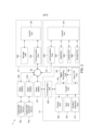
- Fig. 1 is a diagram showing a configuration of a fish species discrimination system according to an embodiment.
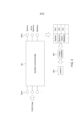
- Fig. 2 is a block diagram showing a configuration of a fish species discrimination system according to an embodiment.
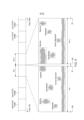
- Fig. 3 is a diagram schematically showing fish species discrimination processing by a neural network according to an embodiment.
- Fig. 4 is a diagram schematically showing a display example of an echo image including fish species discrimination results according to an embodiment.
- Fig. 5 is a diagram schematically showing how annotation data is generated in a terminal device according to an embodiment.
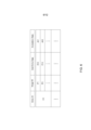
- Fig. 6 is a diagram showing how annotation data is stored in a storage unit of a server according to an embodiment.
- Fig. 7 is a flowchart showing an annotation data integration process executed by a control unit of a server according to an embodiment.
- Fig. 8 is a flowchart showing a processing of extracting annotation data of a fish school extending over two-unit echo images according to an embodiment.
- Fig. 9(a) and Fig. 9(b) are diagrams schematically showing a state of a fish school near a boundary between a first unit echo image and a second unit echo image according to an embodiment, respectively.
- Fig. 10(a) and Fig. 10(b) are diagrams showing an integration method of annotation data of first and second fish schools according to an embodiment, respectively.
- Fig. 11(a) is a diagram schematically showing a state of a fish school near a boundary between a first unit echo image and a second unit echo image according to a first modification
- Fig. 11(b) is a diagram showing an integration method of annotation data of first and second fish schools according to the first modification.
- Fig. 12 is a flowchart showing a fish species setting process executed in an annotation data integration process according to a second modification.
- server (20) corresponds to "fish species learning device” described in the claims.
- the "fish species learning device” according to the present invention is not necessarily limited to the server (20), and for example, other devices such as terminal devices (50) may perform the functions of the "fish species learning device” according to the present invention.
- Fig. 1 is a diagram showing a configuration of a fish species discrimination system 1.
- the fish species discrimination system (1) is equipped with an underwater detection device (10) and the server (20).
- the underwater detection device (10) is a fish finder installed in a vessel (2).
- the underwater detection device (10) can communicate with the server (20) via an external communication network (30) (for example, the Internet) and a base station (40).
- the underwater detection device (10) and the server (20) each hold address information for communicating with each other.
- the respective address information is set in the underwater detection device (10) and the server (20) at the initial setting.
- the underwater detection device (10) is equipped with a transmitter/receiver (11) and a control unit (12).
- the transmitter/receiver (11) is installed on the bottom of the vessel (2), and the control unit (12) is installed in the wheelhouse or the like of the vessel (2).
- the transmitter/receiver (11) and the control unit (12) are connected by a signal cable (not shown).
- the transmitter/receiver (11) is equipped with an ultrasonic transducer (not shown) for transmitting and receiving waves.
- the transmitter/receiver (11) transmits an ultrasonic wave (3) (transmitted wave) toward a seabed (4) and receives its reflected wave by the ultrasonic transducer in response to control from the control unit (12).
- the transmitter/receiver (11) transmits a received signal based on the received reflected wave to the control unit (12).
- the control unit (12) processes the received signal to generate an echo data indicating echo intensity at each depth.
- the control unit (12) arranges the echo intensity at each depth based on the echo data in time series to generate an echo image for one screen.
- the control unit (12) displays the generated echo image on a display unit.
- the control unit (12) updates the echo image for each ultrasonic wave transmitted and received. A user can grasp presence and location of a fish school (5) by referring to the echo image.
- control unit (12) transmits the generated echo data to the server (20) at any time.
- the server (20) stores the received echo data and generates an echo image similar to that of the control unit (12).
- the server (20) uses a machine learning model (machine learning algorithm) to calculate a prediction probability (probability of being a fish species) for each fish species included in the echo image.
- the server (20) acquires a discrimination result of the fish species for the fish school based on the prediction probabilities for each fish species calculated by the machine learning model.
- the server (20) transmits the discrimination result of the fish species thus acquired along with a range (depth, time) of the fish school to be discriminated to the underwater detection device (10) that received the echo data.
- the underwater detection device (10) Based on the received discrimination result and the range (depth, time) of the fish school, the underwater detection device (10) superimposes the discrimination result of the fish species on the corresponding range on the echo image. Thus, the user can confirm the fish species of each fish school on the echo image and smoothly go ahead with capture of the desired fish.
- the server (20) acquires annotation data (training data) for training the machine learning model from a plurality of terminal devices (50) via an external communication network (30). That is, the server (20) distributes the echo data received from the underwater detection device (10) to any of the plurality of terminal devices (50). The terminal devices (50) are used to generate annotation data from the received echo data.
- the terminal devices (50) are owned by an operator, such as an expert, who generates annotation data.
- the operator causes the terminal devices (50) to display an echo image based on the received echo data, and sets the fish species for each fish school included in these echo images.
- the set fish species is associated with the range (depth, time) of the fish school and the echo data within the range.
- the associated fish species, the range of the fish school and the echo data constitute the annotation data for the fish school.
- the annotation data is transmitted to the server (20) together with an identification information of the echo image on which the annotation data is generated.
- the server (20) uses the received annotation data to teach the machine learning model. This improves accuracy of the machine learning model for fish species discrimination.
- annotation data are generated for the echo data provided by the server (20) to the terminal devices (50).
- the generated annotation data are returned to the server (20).
- the method of providing the annotation data to the server (20) is not limited to this.
- the echo data may be provided to the terminal devices (50) from a device other than the server (20) to generate the annotation data, and the generated annotation data may be provided to the server (20).
- underwater detection device 10 only one underwater detection device 10 is shown in Fig. 1, but in fact, a plurality of underwater detection devices may communicate with the server (20) via the external communication network (30) and the nearest base station.
- the underwater detection devices (10) that communicate with the server (20) may include several types of underwater detection devices with different fishing methods, such as underwater detection devices installed in fixed nets, in addition to those installed on the vessel (2), as shown in Fig. 1.
- Fig. 2 is a block diagram showing the configuration of the fish species discrimination system 1.
- the underwater detection device (10) includes a control unit (101), a display unit (102), an input unit (103), a wave transmit/receive unit (104), a signal processing unit (105), a communication unit (106), and a position detection unit (107).
- the control unit (101) is composed of a microcomputer, a memory, etc.
- the control unit (101) controls each part of the underwater detection device (10) according to a program stored in the memory.
- the display unit (102) is equipped with a monitor and displays an image by control from the control unit (101).
- the input unit (103) is equipped with a trackball for moving a cursor on the image displayed on the display unit (102), an operation key, etc., and outputs a signal corresponding to an operation from the user to the control unit (101).
- the display unit (102) and the input unit (103) may be integrally constituted by a liquid crystal touch panel, etc.
- the wave transmit/receive unit (104) includes the transmitter/receiver (11), as shown in Fig. 1, a transmission circuit (not shown) for supplying a transmission signal to the transmitter/receiver (11), and a reception circuit (not shown) for processing the received signal output from the transmitter/receiver (11) and outputting it to the signal processing unit (105).
- the transmission and reception circuits are included in the control unit (12), as shown in Fig. 1.
- the wave transmit/receive unit (104) transmits a transmission wave (ultrasonic wave) of a given frequency according to the control from the control unit (101).
- the wave transmit/receive unit (104) receives the reflected wave of the transmission wave and outputs the received signal.
- the reception circuit extracts the received signal of the frequency of the transmission wave and outputs it to the signal processing unit (105).
- the signal processing unit (105) generates echo data indicating the intensity of the reflected wave according to the depth from the received signal input from the wave transmit/receive unit (104), and outputs the generated echo data to the control unit (101).
- An elapsed time from a timing of transmitting the transmission wave corresponds to the depth.
- the intensity of the reflected wave decreases as the depth increases. Therefore, the signal processing unit (105) corrects the intensity of the reflected wave that decreases according to the elapsed time and outputs the corrected intensity echo data to the control unit (101) so that echo data can be quantitatively handled regardless of depth difference.
- the control unit (101) generates the echo image based on the received echo data and causes the display unit (102) to display it. From the echo data, the control unit (101) generates one row of image in the depth direction in which the echo intensity at each depth is expressed in gradation by a color scale. The control unit (101) integrates the images of each row from the present time to a given time in the past in the time direction to generate the echo image for one screen.
- the communication unit (106) is a communication module capable of wireless communication with the base station (40).
- the position detection unit (107) is equipped with GPS and detects a position of the underwater detection device (10).
- the position detection unit (107) outputs the detected position information to the control unit (101).
- control unit (101) transmits echo data to the server (20) via the communication unit (106) at any time.
- the control unit (101) also receives the fish species discrimination result from the server (20) via the communication unit (106).
- the control unit (101) further transmits the position information detected by the position detection unit (107) to the server (20).
- a plurality of underwater detection devices (10a, 10b ...) may communicate with the server (20) via the external communication network (30) and the nearest base stations (40a, 40b .
- the underwater detection device (10) that communicates with the server (20) includes the one installed on the vessel (2), as shown in Fig. 1, as well as several types of underwater detection devices with different fishing methods, such as underwater detection devices installed in fixed nets.
- the basic configuration of the other underwater detection devices is similar to that of the underwater detection device (10), as shown in Fig. 2.
- the server (20) includes a control unit (201), a storage unit (202), and a communication unit (203).
- the control unit (201) is composed of a CPU or the like.
- the storage unit (202) is composed of a ROM, a RAM, a hard disk or the like.
- the storage unit (202) stores a program for fish species discrimination and a program for machine learning.
- the control unit (201) controls each unit according to the program stored in the storage unit (202).
- the communication unit (203) communicates with the underwater detection device (10) via the external communication network (30) and the base station (40) under control from the control unit (201).
- the server (20) also communicates with the plurality of terminal devices (50) via the external communication network (30).
- the terminal devices (50) are devices such as personal computers and tablet-type computers that can input and output information.
- the terminal devices (50) are provided with a control unit (501), a storage unit (502), a display unit (503), an input unit (504), and a communication unit (505).
- the control unit (501) is composed of a CPU or the like.
- the storage unit (502) is composed of a ROM, a RAM, a hard disk or the like.
- the storage unit (502) stores a program for generating annotation data.
- the control unit (501) controls each unit according to the program stored in the storage unit (502).
- the display unit (503) is composed of a liquid crystal monitor or the like, and displays an image under control from the control unit (501).
- the input unit (504) is provided with input means such as a mouse and a keyboard.
- the communication unit (505) communicates with the server (20) by control from the control unit (501).
- Fig. 3 is a diagram schematically showing the fish species discrimination processing by a neural network.
- machine learning using a neural network is applied as the machine learning.
- a neural network by deep learning combining the neurons in multiple stages is applied.
- the machine learning applied is not limited to this, and other machine learning such as support vector machines and decision trees may be applied.
- the control unit (201) of the server (20) extracts the range (depth, time) of the fish school from the echo data of one screen to be processed. On the echo image, an area where the echo intensity is above a given threshold and where the echo intensity is connected is extracted as the fish school, and a rectangular range composed of the maximum time width and maximum depth width of the fish school is extracted as the range of the fish school.
- the description in the applicant's earlier application, International Publication No. 2019/003759 is incorporated by reference.
- the control unit (201) applies the echo data of the range of the extracted fish school to inputs (301a) of a machine learning model (machine learning algorithm by neural network) (301), as shown in Fig. 3.
- a machine learning model machine learning algorithm by neural network
- Items of fish species such as sardine, horse mackerel and mackerel are assigned to the outputs (301b) of the machine learning model (301).
- probability that the fish species of the fish school is the fish species of each item is outputted from each item of outputs (301b) of the machine learning model (301).
- prediction probability probability that the fish species of the fish school is the fish species of each item.
- the prediction probability of 85% is outputted from the sardine item
- the prediction probability of 70% is outputted from the mackerel item
- the prediction probability of 10% is outputted from the horse mackerel item.
- the prediction probability of each item is checked against an output condition (302).
- the output condition (302) for example, a condition is applied in which the fish species of the item whose prediction probability is equal to or greater than a given lower limit and which has the highest rank is outputted as a discrimination result (303).
- the lower limit is set in order to prevent fish species with low probability from being outputted as the discrimination result.
- sardine with a prediction probability of 85% is outputted as the fish species discrimination result (303).
- the machine learning for the machine learning model (301) is performed by sequentially applying a series of annotation data (training data) to the inputs (301a) and the outputs (301b) of the machine learning model (301). That is, the echo data of the fish school having an annotation data is inputted to inputs (301a) of the machine learning model (301), and the item corresponding to the fish species included in the annotation data is set to 100% in the outputs (301b) of the machine learning model (301), and the other items are set to 0% to perform machine learning.
- annotation data may further include the other information.
- Fig. 4 is a diagram schematically showing a display example of an echo image (P1) including fish species discrimination results.
- P1 an echo image
- a line in the depth direction is attached only to the part where the echo intensity is high.
- a frame-shaped marker (M0) indicating the range of the fish school is displayed in an area on the echo image (P1) corresponding to the depth width and time width corresponding to the received range of the fish school. Furthermore, the control unit (101) further displays a label (L0) indicating the received discrimination result of the fish school around the marker (M0).
- the marker M0 is displayed for fish schools F1 to F8. Further, the label (L0) indicating the discrimination result of the fish species is displayed around these markers (M0). The current date and time is displayed near the upper left corner of the echo image (P1).
- the marker and label are not displayed for the fish school (F9) because the result of the fish species discrimination was not outputted according to the machine learning model (301) and the output condition (302 of Fig. 3.). This can happen, for example, if the prediction probability of the fish school (F9) by the machine learning model (301) does not satisfy the output condition (302). In such a case, because the discrimination result is not transmitted from the server (20) to the underwater detection device (10) for this fish school, the discrimination result of the fish species is not displayed as in the case of the fish school (F9 in Fig. 4).
- Fig. 5 is a diagram schematically showing a generation method of annotation data performed in the terminal device (50).
- the generation of annotation data is performed in the terminal device (50) by displaying the echo image based on the echo data to be processed on the display unit (503).
- An operator such as a specialist designates the range of the fish school on the displayed echo image.
- the range of the fish school is specified by a rectangular range.
- the operator manipulates the input unit (504) to specify the range of the fish school by specifying apexes of the diagonal of the rectangle.
- the operator manipulates the input unit (504) to set the fish species for each fish school. For example, according to the specification of the range of the fish school, a list of fish species selection candidates is displayed in the display unit (503), and the operator selects the fish species to be set from this list. Thus, the fish species is set in the range of the fish school.
- the generation of annotation data is performed for each unit echo image as shown in Fig. 5. That is, a series of echo images of a given time is divided into multiple units with a time width corresponding to one frame, and a plurality of unit echo images targeted for the generation of annotation data are generated. Of the boundaries (B1) and (B2) of the unit echo images in the time direction, the boundary (B1) on a side with the new time coincides with the boundary (B2) on a side with the old time of the next unit echo image.
- the operator For each unit echo image, the operator, such as a specialist, specifies the range of the fish school and further sets the fish species for the specified fish school. This generates annotation data in which the range of the fish school, the fish species in the range of the fish school and the image data (echo data) included in the range of the fish school are associated.
- the range of five fish schools or the range of rectangular dashed lines is specified by annotation processing (An) on the unit echo image (Pn), and the fish species is set in the range of each fish school.
- the range of five fish schools or the range of rectangular dashed lines is specified by annotation processing (An + 1) on the unit echo image (Pn + 1), and the fish species is set in the range of each fish school. Therefore, from the unit echo image (Pn), for each of the five fish schools, annotation data in which the range of the fish school, the fish species in the range of the fish school, and the image data (echo data) included in the range of the fish school are associated is generated.
- the annotation data thus generated is transmitted from the terminal device (50) to the server (20) and stored in the storage unit (202) of the server (20).
- Fig. 6 shows a storage form of the annotation data in the storage unit (202) of the server (20).
- unit echo data and annotation data are stored in the storage unit (202) in association with an echo ID and an image ID.
- the echo ID is identification information for identifying the above-described series of echo images (echo data) of the given time.
- the echo ID is set uniquely by the server (20).
- the image ID is identification information for identifying the unit echo image.
- the image ID is, for example, a number assigned to each unit echo image in order from the oldest one.
- the unit echo data is echo data for one frame corresponding to each unit echo image.
- the annotation data is annotation data generated from each unit echo image.
- the control unit (201) of the server (20) When the control unit (201) of the server (20) newly receives echo data for a given time to be subjected to annotation processing from the underwater detection device (10) or the like, it attaches the echo ID to the echo data. Furthermore, the control unit (201) divides the echo data by a time width of one frame from the beginning of the side with the old time to generate unit echo data corresponding to each unit echo image. Then, the control unit (201) attaches the image ID to each unit echo data and stores the unit echo data in the storage unit (202) in association with the image ID. In this way, the echo ID, the image ID and the unit echo data are configured in the data structure of Fig. 6.
- control unit (201) sends each unit echo data together with the echo ID and the image ID to the terminal device (50).
- the control unit (501) of the terminal device (50) stores these received data in the storage unit (502) for annotation processing by the operator.
- the control unit (501) causes the display unit (503) to display the unit echo image based on the unit echo data to be processed.
- the operator performs annotation processing on the unit echo image to be processed by the processing, as shown in Fig. 5. This generates annotation data for the unit echo image.
- the control unit (501) transmits the annotation data generated for each unit echo image to the server (20) along with the echo ID in association with the image ID of each unit echo image.
- the control unit (201) of the server (20) stores the received annotation data in the storage unit (202) in association with the image ID of Fig. 6.
- the annotation data corresponding to the number of fish schools included in the unit echo image is associated with each image ID.
- the unit echo image shown in Fig. 5 does not necessarily include a fish school in its entirety, and one fish school may extend over two temporally consecutive unit echo images.
- the sardine fish school in the upper right of the unit echo image (Pn) is thought to be connected to the sardine fish school in the upper left of the next unit echo image (Pn + 1).
- the sardine fish school extending over the unit echo image (Pn) and the unit echo image (Pn + 1) is divided and specified into the unit echo image (Pn) and the unit echo image (Pn + 1).
- Annotation data would then be generated individually for each separated fish school part.
- the present embodiment enhances accuracy of the machine learning, from the annotation data of two temporally consecutive unit echo images.
- the annotation data of the fish school extending over these unit echo images are extracted, respectively, and the extracted two annotation data are integrated to generate the annotation data of the fish school.
- the annotation data of the sardine fish school at the upper right of the unit echo image (Pn) and the annotation data of the sardine fish school at the upper left of the unit echo image (Pn + 1) are integrated to generate the annotation data for the entire sardine fish school.
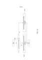
- Fig. 7 is a flowchart showing an annotation data integration process executed by the control unit (201) of the server (20).
- the control unit (201) refers to the annotation data of two temporally consecutive unit echo images among the unit echo images (unit echo data) of the same echo ID (S11).
- the control unit (201) extracts the annotation data of the fish school extending over these two-unit echo images from the referred annotation data (S12).
- the control unit (201) integrates the extracted annotation data to generate the annotation data of the entire fish school extending over the two-unit echo images, and stores the generated annotation data in the storage unit (202) (S13).
- the control unit (201) performs the processing of Fig. 7 for all unit echo images (unit echo data) of the same echo ID.
- the annotation data of Fig. 6 generated by the terminal device (50) and the annotation data generated by the annotation processing of Fig. 7, are used.
- the two annotation data integrated by the processing of Fig. 7 may be excluded from the annotation data used for machine learning.
- the two annotation data integrated by the processing of Fig. 7 may be erased from the data structure of Fig. 6 constructed in the storage unit (202).
- Fig. 8 is a flowchart showing an example of the processing in step (S12) of Fig. 7.
- Fig. 8 includes steps (S11) and (S13) of Fig. 7. Steps (S101) to (S105) of Fig. 8 correspond to step (S12) of Fig. 7.
- the control unit (201) refers to the annotation data of two consecutive unit echo images, at step (S11), and grasps the range of the fish school in each annotation data.
- the control unit (201) determines whether a fish school exists near the right boundary (near the boundary B1 in Fig. 5) (S101). In one case, if no fish school exists near the boundary (B1) on the right side of the first unit echo image (S101: NO), the control unit (201) terminates the processing in Fig. 8. In another case, if a fish school exists near the boundary (B1) on the right side of the first unit echo image (S101: YES), the control unit (201) identifies this fish school as a first fish school to be integrated, at step (S102).
- control unit (201) determines whether a fish school exists near the boundary on the left side (that is, near the boundary (B2 in Fig. 5)) of the second unit echo image, at step (S103) corresponding to the newer of these two unit echo images. In one case, when there is no fish school near the left boundary (B2) of the second unit echo image (S103: NO), the control unit (201) terminates the processing of Fig. 8. In another case, when there is a fish school near the left boundary (B2) of the second unit echo image (S103: YES), the control unit (201) identifies this fish school as a second fish school to be integrated, at step (S104).
- the control unit (201) determines whether a depth range of the first fish school roughly matches that of the second fish school, at step (S105). More specifically, the control unit (201) determines whether a match rate between the depth range of the first fish school and that of the second fish school is more than a given threshold (Th1) or not. In one case, when the determination at step (S105) is NO, the control unit (201) terminates the processing in Fig. 8 without performing the processing at step (S13).
- the control unit (201) integrates the annotation data of the first and second fish schools, at step (S13) and generates the annotation data of the entire fish school, assuming that the first and second fish schools constitute a fish school extending over the first unit echo image and the second unit echo image (S13). With this, the control unit (201) terminates the processing for the annotation data of these two-unit echo images.
- the control unit (201) performs the processing of Fig. 8 for the annotation data of the next two temporally consecutive unit echo images. Thus, the control unit (201) performs the processing of Fig. 8 for the annotation data of all the unit echo images with the same echo ID.
- Fig. 9(a) and Fig. 9(b) schematically show a state of the fish school near the boundary between the first unit echo image and the second unit echo image.
- Fig. 9(a) shows the upper right portion of the unit echo image (Pn) (first unit echo image) and the upper left portion of the unit echo image (Pn + 1) (second unit echo image), as shown in Fig. 5.
- (Fa) and (Fb) are sardine fish schools
- (Ra) and (Rb) are the range (time range, depth range) of fish schools included in the annotation data. As described above, the ranges (Ra, Rb) of the fish schools are set to be rectangular.
- step (S101) of Fig. 8 it is determined whether a fish school exists in a given time range (Ta) from the boundary (B1) of the first unit echo image (Pn), and at step (S103), it is determined whether a fish school exists in a given time range (Tb) from the boundary (B2) of the second unit echo image (Pn + 1).
- the time ranges (Ta) and (Tb) are set to the order of the maximum value of a temporal gap on the echo image that can occur in a fish school.
- the time ranges (Ta) and (Tb) may be set to the same time width.
- Fig. 9(a) since the fish school (Fa) (fish school range Ra) exists within the time range (Ta), the determination at step (S101) of Fig. 8 is YES and the fish school (Fa) is identified as the first fish school.
- the determination at step (S103) of Fig. 8 since the fish school (Fb) (fish school range Rb) exists within the time range (Tb), the determination at step (S103) of Fig. 8 is YES and the fish school (Fb) is identified as the second fish school.
- step (S105) of Fig. 8 the determination is made according to the following equation (1).
- (Amax) and (Amin) are the maximum and minimum depths of the first fish school (Fa) (fish school range Ra) in the first unit echo image (Pn), and (Bmax) and (Bmin) are the maximum and minimum depths of the second fish school (Fb) (fish school range Rb) in the second unit echo image (Pn + 1), respectively.
- the denominator on the left side of equation (1) is the depth range from the smaller (shallower) of (Amin) and (Bmin) to the larger (deeper) of (Amax) and (Bmax), and in the example of Fig. 9(a), it is the depth range from (Amin) to (Bmax).
- the numerator on the left side of equation (1) is the depth range from the larger (deeper) of (Amin) and (Bmin) to the smaller (shallower) of (Amax) and (Bmax), and in the example of Fig. 9(a), it is the depth range from (Bmin) to (Amax).
- the left side of equation (1) calculates the match rate between the depth range of the first fish school (Fa) and the depth range of the second fish school (Fb).
- step (S105) of Fig. 8 whether or not the depth range of the first fish school (Fa) roughly matches the depth range of the second fish school (Fb) is determined depending on whether or not the match rate is above the threshold (Th1).
- the threshold (Th1) may be a statistically set default value or may be set arbitrarily by the administrator of the server (20).
- Fig. 10(a) and Fig. 10(b) are diagrams showing a method of integrating the annotation data of the first and second fish schools at step (S13) of Fig. 8.
- the control unit (201) matches the depth range of the fish school range (Ra) of the first fish school (Fa) and the fish school range (Rb) of the second fish school (Fb). That is, as shown in Fig. 10(a), the control unit (201) modifies the depth range of the fish school ranges (Ra and Rb) so that the smaller of the maximum depths (Amax) and (Bmax) (Amax) matches the larger (Bmax) and the larger of the minimum depths (Amin) and (Bmin) (Bmin) matches the smaller (Amin). Then, as shown in Fig. 10(b), the control unit (201) integrates the annotation data of the modified fish school ranges (Ra) and (Rb) to generate the annotation data of one fish school composed of the fish schools (Fa) and (Fb).
- the generated annotation data consists of the modified fish school range (Rab) integrating the modified fish school ranges (Ra) and (Rb), the echo data contained in the fish school range (Rab), and the fish species (sardine in this case) of the fish school.
- the fish school range (Rab) is also rectangular, and this rectangular range contains the fish schools (Fa) and (Fb).
- the control unit (201) of the server (20) uses the annotation data after integration for training the machine learning model (301).
- the annotation data (first and second annotation data) of a fish school extending over the first unit echo image (Pn) and the second unit echo image (Pn + 1) are integrated to generate annotation data for the fish school in its entirety. Therefore, since the annotation data for the entire fish school can be used for machine learning, the accuracy of machine learning for fish species discrimination can be enhanced.
- the control unit (201) identifies in the first unit echo image (Pn) the fish school (Fa) extending to the vicinity of the boundary (B1) (first boundary) on the side of the second unit echo image (Pn + 1) as the first fish school, identifies in the second unit echo image (Pn + 1) the fish school (Fb) extending to the vicinity of the boundary (B2) (second boundary) on the side of the first unit echo image (Pn) as the second fish school, and when the range Ra of the fish school Fa (first fish school) and the range (Rb) of the fish school (Fb) (second fish school) roughly match, the annotation data of these fish schools (Fa) and (Fb) (first and second fish schools) are extracted as the annotation data (first and second annotation data) to be integrated, respectively.
- the control unit (201) extracts the fish school (Fa) at least partially included in the given time range (Ta) from the boundary (B1) (first boundary), as the fish school to be integrated (first fish school), and extracts the fish school (Fb) at least partially included in the given time range (Tb) from the boundary (B2) (second boundary), as the fish school to be integrated (second fish school).
- This enables the first and second fish schools, which constitute the fish school extending over the first unit echo image (Pn) and the second unit echo image (Pn + 1), to be identified without omission in the first unit echo image (Pn) and the second unit echo image (Pn + 1) even when the distribution of fish is sparse near the boundaries (B1) and (B2). Therefore, the annotation data of one entire fish school can be properly generated.
- the present invention is not limited to the above embodiment, and the embodiment of the present invention can be modified in various ways other than the above configuration.
- the range (time range, depth range) of the fish school constituting the annotation data is rectangular, but the range of the fish school constituting the annotation data may be any other shape other than rectangular.
- the ranges (Ra, Rb) of the fish schools may be shaped along the outer edge of the fish schools (Fa, Fb).
- the area where the echo intensity is above a given threshold and where the echo intensity is connected is extracted as the fish schools (Fa, Fb)
- the range along the outer edge of the extracted fish schools (Fa, Fb) is extracted as the fish school ranges (Ra, Rb).
- step (S101) of Fig. 8 it is determined whether a fish school exists in the time range (Ta) from the boundary (B1), and in step (S103), it is determined whether a fish school exists in the time range (Tb) from the boundary (B2).
- fish schools (Fa) and (Fb) are identified as the first fish school and the second fish school, respectively.
- step (S105) of Fig. 8 whether or not the depth range of fish school (Fa) (first fish school) roughly matches that of fish school (Fb) (second fish school) is determined based on the match rate between the depth range of fish school (Fa) (first fish school) near boundary (B1) (first boundary) and the depth range of fish school (Fb) (second fish school) near boundary (B2) (second boundary).
- the maximum depth (Amax) and the minimum depth (Amin) are obtained for the portion of the fish school range (Ra) included in the time range (Ta)
- the maximum depth (Bmax) and the minimum depth (Bmin) are obtained for the portion of the fish school range (Rb) included in the time range (Tb).
- the control unit (201) applies the obtained maximum depths Amax and Bmax and minimum depths Amin and Bmin to equation (1) above to determine step S105.
- step S105 determines whether the depth range of fish school (Fa) (first fish school) roughly matches that of fish school (Fb) (second fish school) in the vicinity of boundaries (B1) (first boundary) and (B2) (second boundary).
- the range (Rab) of the entire fish school can be set by connecting the positions of the acquired maximum depths (Amax) and (Bmax) from the ranges (Ra) and (Rb) of the fish schools to each other and by connecting the positions of the acquired minimum depths (Amin) and (Bmin) from the ranges (Ra) and (Rb) of the fish schools to each other as in Fig. 11(b).
- the range (Rab) of the fish school constituting the annotation data of the entire fish school can be set smoothly and appropriately.
- the method of setting the range (Rab) of the fish school is not limited to this.
- the range (Rab) of the fish school may be set by connecting the positions of the ranges (Ra) and (Rb) of the fish school slightly closer to the boundaries (B1) and (B2) than the positions of the acquired maximum depths (Amax) and (Bmax) from the ranges (Ra) and (Rb) of the fish schools, and by connecting the positions of the ranges (Ra) and (Rb) of the fish school slightly closer to the boundaries (B1) and (B2) than the positions of the acquired minimum depths (Amin) and (Bmin) from the ranges (Ra) and (Rb) of the fish schools.
- the range (Rab) of the fish school constituting the annotation data of the entire fish school can be set smoothly and appropriately.
- the fish species constituting the annotation data of the first fish school and the fish species constituting the annotation data of the second fish school are the same.
- judging fish species based on images of fish schools can be difficult for the operator.
- the fish species in the annotation data set for the first and second fish schools, respectively, identified as constituting one fish school may differ from each other.
- the fish species is set for the annotation data after integration based on a given condition.
- Fig. 12 is a flowchart showing the fish species setting process executed in the annotation data integration process in step (S13) of Fig. 8.
- the control unit (201) determines whether the fish species of the annotation data of the first and second fish schools to be integrated match, at step (S201). In one case, if both match (S201: YES), the control unit (201) sets the matching fish species as the fish species of the fish school after integration, at step (S202). On the other hand, if both do not match, (S201: NO), the control unit (201) sets the fish species of the fish school after integration according to a given setting condition, at step (S203).
- the setting condition of step (S203) may include, for example, setting the fish species of the annotation data to the newer of the annotation data of the first and second fish schools (first annotation data, second annotation data).
- the control unit (201) sets the fish species of the annotation data of the fish school Fb acquired from the newer unit echo image (Pn + 1) as the fish species for the range (Rab) of the integrated fish school.
- the setting condition at step (S203) is not limited to the condition (first condition) of setting the fish species to the newer annotation data as described above, and may be another condition as long as a highly reliable fish species can be set for the annotation data after integration.
- the setting condition at step (S203) may include the condition (second condition) of setting the fish species of the annotation data of the integrated fish school to the fish species of the annotation data of the fish school with the larger range among the annotation data (first and second annotation data) of the first and second fish schools to be integrated.
- the setting condition at step (S203) may include the condition (third condition) of setting the fish species of the annotation data of the integrated fish school to the fish species obtained by processing with the fish species discrimination machine learning model (301).
- the first or third condition may be applied to set the fish species.
- the fish species acquired by the first to third conditions respectively the fish species with the highest number of fish species matching each other may be set as the fish species in the annotation data of the integrated fish school.
- the setting conditions are not limited to the first to third conditions but may further include other conditions.
- the control unit (201) may exclude both the annotation data of the first fish school and the second fish school from the annotation data used for machine learning of the machine learning model (301), or one of these annotation data (for example, the older or the fish school with the smaller range) may be excluded from the annotation data used for machine learning of the machine learning model (301).
- the processes of Figs. 7 and 8 are performed in the control unit (201) of the server (20), but these processes may be performed in other devices other than the server (20), and the annotation data after the integration may be provided to the server (20).
- the processes of Figs. 7 and 8 may be performed by the control unit (501) of the terminal device (50) after the generation of the annotation data by the operator, and the annotation data generated by the operator and the annotation data generated by the processes of Figs. 7 and 8 may be transmitted by the control unit (501) to the server (20).
- the terminal device (50) corresponds to the fish species learning device described in the claims.
- the method for extracting the annotation data of the fish school extending over the first unit echo image and the second unit echo image is not limited to the method shown at steps (S101) to (S105) in Fig. 8.
- the frequency of the transmission wave transmitted by the wave transmit/receive unit (104) is one frequency, but a transmission wave with two different frequencies may be transmitted from the wave transmit/receive unit (104).
- the echo data based on the received signal of each frequency may be applied to the machine learning model (301) for each fish school to determine the fish species of each fish school.
- the fish species determination by the machine learning model (301) can be performed with higher accuracy.
- the presence or absence of a swim bladder causes a difference in the echo intensity at each frequency. Therefore, by referring to the difference in the echo intensity from a fish school, the fish species in that fish school can be accurately identified.
- the annotation data generated by the unit echo image may be generated for each fish school at each frequency.
- the integration processing of the annotation data shown in Figs. 7 and 8 need only be performed individually for the echo data (unit echo image) of each frequency.
- the determination of the fish species using the machine learning model (301) is performed on the server (20) side, but this determination processing may be performed on the underwater detection device (10) side.
- the machine learning model (301) updated by the annotation data is transmitted to the underwater detection device (10) at any time and stored in the underwater detection device (10).
- the control unit (101) of the underwater detection device (10) executes fish species discrimination using the machine learning model (301), as in the control unit (201) of the above server (20), and displays the result of the discrimination on the echo image.
- the annotation data is generated in the terminal device (50), but the device generating the annotation data is not limited to this.
- a user of the underwater detection device (10) may input a fish school and its fish species on the echo image from his/her own catch result, and the echo data of this fish school and the fish species in the fish school may be transmitted as annotation data to the server (20).
- the underwater detection device (10) is a fish finder, but the underwater detection device (10) may be a device other than a fish finder such as sonar.
Landscapes
- Engineering & Computer Science (AREA)
- Physics & Mathematics (AREA)
- Remote Sensing (AREA)
- Radar, Positioning & Navigation (AREA)
- General Physics & Mathematics (AREA)
- Computer Networks & Wireless Communication (AREA)
- Business, Economics & Management (AREA)
- Human Resources & Organizations (AREA)
- Strategic Management (AREA)
- Economics (AREA)
- Theoretical Computer Science (AREA)
- Marketing (AREA)
- General Business, Economics & Management (AREA)
- Tourism & Hospitality (AREA)
- Entrepreneurship & Innovation (AREA)
- Quality & Reliability (AREA)
- Operations Research (AREA)
- Development Economics (AREA)
- Acoustics & Sound (AREA)
- Game Theory and Decision Science (AREA)
- Data Mining & Analysis (AREA)
- Life Sciences & Earth Sciences (AREA)
- Agronomy & Crop Science (AREA)
- Animal Husbandry (AREA)
- Marine Sciences & Fisheries (AREA)
- Mining & Mineral Resources (AREA)
- Health & Medical Sciences (AREA)
- General Health & Medical Sciences (AREA)
- Primary Health Care (AREA)
- Measurement Of Velocity Or Position Using Acoustic Or Ultrasonic Waves (AREA)
Abstract
Description
Effect of the embodiment
First Modification
Second Modification
Other Modifications
20 server (machine learning device)
201 control unit
202 storage unit
301 machine learning model
Pn, Pn + 1 unit echo images (first unit echo image, second unit echo image)
Fa, Fb fish schools (first and second fish schools)
B1, B2 boundaries (first boundary, second boundary)
Ta, Tb time ranges
Claims (8)
- A fish species learning device (20), comprising:
a storage unit (202) configured to store annotation data for each unit echo image (Pn, Pn+1); and
a control unit (201), wherein
the control unit is configured to:
extract a first annotation data and a second annotation data of a fish school (5) extending over a first unit echo image (Pn) and a second unit echo image (Pn+1) from the annotation data of the first unit echo image and the second unit echo image, respectively, the first unit echo image (Pn) and the second unit echo image (Pn+1) being temporally consecutive in time, and
generate the annotation data of the fish school (5) in its entirety by integrating the extracted first annotation data and second annotation data. - The fish species learning device (20) of claim 1, wherein
the control unit (201) is configured to:
identify in the first unit echo image (Pn) a first fish school (Fa) extending to a vicinity of a first boundary (B1) on a side of the second unit echo image (Pn+1) and identify in the second unit echo image (Pn+1) a second fish school (Fb) extending to a vicinity of a second boundary (B2) on a side of the first unit echo image (Pn), and
extract the annotation data of the first fish school (Fa) and the second fish school (Fb) as the first annotation data and the second annotation data, respectively, when a depth range of the first fish school (Fa) and a depth range of the second fish school (Fb) substantially match. - The fish species learning device (20) of claim 2, wherein
the control unit (201) is configured to:
determine whether the depth range of the first fish school (Fa) and the depth range of the second fish school (Fb) substantially match based on a match rate between the depth range of the first fish school (Fa) near the first boundary (B1) and the depth range of the second fish school (Fb) near the second boundary (B2). - The fish species learning device (20) of claim 2, wherein
the control unit (201) is configured to:
extract, as the first fish school (Fa), a fish school at least partially included in a given time range from the first boundary (B1), and extract, as the second fish school (Fb), a fish school at least partially included in a given time range from the second boundary (B2). - The fish species learning device (20) of claim 1, wherein
when a fish species included in the first annotation data is different from a fish species included in the second annotation data, the control unit (201) is configured to set a fish species of the annotation data of the fish school based on a given setting condition. - The fish species learning device (20) of claim 5, wherein
the given setting condition includes setting the fish species of the annotation data to the newer of the first annotation data and the second annotation data. - A fish species learning method, comprising:
extracting a first annotation data and a second annotation data of a fish school extending over a first unit echo image (Pn) and a second unit echo image (Pn+1) from annotation data of the first unit echo image (Pn) and the second unit echo image (Pn+1), respectively, the first unit echo image (Pn) and the second unit echo image (Pn+1) being temporally consecutive in time, and
generating the annotation data of the fish school in its entirety by integrating the extracted first annotation data and second annotation data. - A program comprising functions which, when executed by a computer, cause the computer to:
extract a first annotation data and a second annotation data of a fish school extending over a first unit echo image (Pn) and a second unit echo image (Pn+1) from annotation data of the first unit echo image (Pn) and the second unit echo image (Pn+1), respectively, the first unit echo image (Pn) and the second unit echo image (Pn+1) being temporally consecutive in time, and
generate the annotation data of the fish school in its entirety by integrating the extracted first annotation data and second annotation data.
Priority Applications (1)
| Application Number | Priority Date | Filing Date | Title |
|---|---|---|---|
| GB2417701.6A GB2633715A (en) | 2022-08-16 | 2023-05-26 | Device, method, and program for learning fish species |
Applications Claiming Priority (2)
| Application Number | Priority Date | Filing Date | Title |
|---|---|---|---|
| JP2022-129707 | 2022-08-16 | ||
| JP2022129707A JP2024027023A (en) | 2022-08-16 | 2022-08-16 | Fish species learning device, fish species learning method and program |
Publications (1)
| Publication Number | Publication Date |
|---|---|
| WO2024038653A1 true WO2024038653A1 (en) | 2024-02-22 |
Family
ID=89941763
Family Applications (1)
| Application Number | Title | Priority Date | Filing Date |
|---|---|---|---|
| PCT/JP2023/019775 Ceased WO2024038653A1 (en) | 2022-08-16 | 2023-05-26 | Device, method, and program for learning fish species |
Country Status (3)
| Country | Link |
|---|---|
| JP (1) | JP2024027023A (en) |
| GB (1) | GB2633715A (en) |
| WO (1) | WO2024038653A1 (en) |
Citations (2)
| Publication number | Priority date | Publication date | Assignee | Title |
|---|---|---|---|---|
| JP2014190787A (en) * | 2013-03-27 | 2014-10-06 | Royal Kogyo Kk | Fish detection system |
| EP3761059A1 (en) * | 2019-07-03 | 2021-01-06 | Furuno Electric Company Limited | Systems and methods for generating training dataset for discrimination of fish species |
-
2022
- 2022-08-16 JP JP2022129707A patent/JP2024027023A/en active Pending
-
2023
- 2023-05-26 WO PCT/JP2023/019775 patent/WO2024038653A1/en not_active Ceased
- 2023-05-26 GB GB2417701.6A patent/GB2633715A/en active Pending
Patent Citations (2)
| Publication number | Priority date | Publication date | Assignee | Title |
|---|---|---|---|---|
| JP2014190787A (en) * | 2013-03-27 | 2014-10-06 | Royal Kogyo Kk | Fish detection system |
| EP3761059A1 (en) * | 2019-07-03 | 2021-01-06 | Furuno Electric Company Limited | Systems and methods for generating training dataset for discrimination of fish species |
Also Published As
| Publication number | Publication date |
|---|---|
| GB202417701D0 (en) | 2025-01-15 |
| GB2633715A (en) | 2025-03-19 |
| JP2024027023A (en) | 2024-02-29 |
Similar Documents
| Publication | Publication Date | Title |
|---|---|---|
| US11551433B2 (en) | Apparatus, method and computer program for analyzing image | |
| EP3488387B1 (en) | Method for detecting object in image and objection detection system | |
| US20190204416A1 (en) | Target object detecting device, method of detecting a target object and computer readable medium | |
| JP2024005623A (en) | Server, fish species discrimination system, fish species discrimination method and program | |
| KR102340184B1 (en) | Apparatus and method for tracking a manual target using AI learning technique in the console terminal | |
| CN111602138A (en) | Object detection system and method based on artificial neural network | |
| US11417007B2 (en) | Electronic apparatus and method for controlling thereof | |
| JP2016165238A (en) | Same fish determination device, fish counting device, mobile terminal for fish counting, same fish determination method, fish counting method, number of fish estimation device, number of fish estimation method, same fish determination system, fish counting system and number of fish estimation system | |
| US11449975B2 (en) | Object count estimation apparatus, object count estimation method, and computer program product | |
| JP7334801B2 (en) | LEARNING DEVICE, LEARNING METHOD AND LEARNING PROGRAM | |
| CN111126209B (en) | Lane line detection method and related equipment | |
| US12423602B2 (en) | Data-creation assistance apparatus and data-creation assistance method | |
| KR20210135206A (en) | Method, apparatus and computer program for conducting automatic driving data labeling | |
| JP2022513225A5 (en) | ||
| WO2024038653A1 (en) | Device, method, and program for learning fish species | |
| WO2024057626A1 (en) | Device, system, method, and program for learning fish species | |
| CN111374706B (en) | A fetal heart rate display method, ultrasonic imaging device, and storage medium | |
| WO2024018989A1 (en) | Fish species discrimination system, server, fish species discrimination method and program | |
| US8761480B2 (en) | Method and system for vascular landmark detection | |
| CN111126204B (en) | Method for detecting drivable area and related equipment | |
| EP4553783A1 (en) | Object association method, computer device, computer readable storage medium, and vehicle | |
| KR102128006B1 (en) | Apparatus and method for classifying active pulse | |
| KR101886856B1 (en) | System and method for data combining based on result of non-rigid object tracking on multi-sensor seeker | |
| US20240062050A1 (en) | Auxiliary Visualization Network | |
| WO2021125936A1 (en) | A rf model based insect identification method |
Legal Events
| Date | Code | Title | Description |
|---|---|---|---|
| 121 | Ep: the epo has been informed by wipo that ep was designated in this application |
Ref document number: 23854692 Country of ref document: EP Kind code of ref document: A1 |
|
| ENP | Entry into the national phase |
Ref document number: 202417701 Country of ref document: GB Kind code of ref document: A Free format text: PCT FILING DATE = 20230526 |
|
| WWE | Wipo information: entry into national phase |
Ref document number: 2417701.6 Country of ref document: GB |
|
| NENP | Non-entry into the national phase |
Ref country code: DE |
|
| 122 | Ep: pct application non-entry in european phase |
Ref document number: 23854692 Country of ref document: EP Kind code of ref document: A1 |