WO2024038579A1 - パケット転送制御装置、パケット転送制御方法、振分シミュレーション装置、および、プログラム - Google Patents
パケット転送制御装置、パケット転送制御方法、振分シミュレーション装置、および、プログラム Download PDFInfo
- Publication number
- WO2024038579A1 WO2024038579A1 PCT/JP2022/031353 JP2022031353W WO2024038579A1 WO 2024038579 A1 WO2024038579 A1 WO 2024038579A1 JP 2022031353 W JP2022031353 W JP 2022031353W WO 2024038579 A1 WO2024038579 A1 WO 2024038579A1
- Authority
- WO
- WIPO (PCT)
- Prior art keywords
- candidate
- hash
- information
- calculation algorithm
- flow
- Prior art date
- Legal status (The legal status is an assumption and is not a legal conclusion. Google has not performed a legal analysis and makes no representation as to the accuracy of the status listed.)
- Ceased
Links
Images


Classifications
-
- H—ELECTRICITY
- H04—ELECTRIC COMMUNICATION TECHNIQUE
- H04L—TRANSMISSION OF DIGITAL INFORMATION, e.g. TELEGRAPHIC COMMUNICATION
- H04L47/00—Traffic control in data switching networks
- H04L47/10—Flow control; Congestion control
- H04L47/12—Avoiding congestion; Recovering from congestion
- H04L47/125—Avoiding congestion; Recovering from congestion by balancing the load, e.g. traffic engineering
Definitions
- the present invention relates to a packet transfer control device, a packet transfer control method, a distribution simulation device, and a program that realize distributed control of packets.
- the packet transfer architecture within the data center employs a leaf-and-spine type, and builds a redundant configuration to ensure safety and load distribution.
- the leaf switch selects one of the multiple spine switches to forward the data packet.
- which spine switch to select depends on the load distribution algorithm, and distribution on a per-flow basis and distribution on a per-packet basis are known as existing techniques.
- the present invention has been made in view of these points, and an object of the present invention is to suppress the occurrence of band imbalance in packet load distribution control.
- a packet transfer control device is a packet transfer control device that controls switching to each link in a packet transfer process, and includes packet collection information that is collected from the packet and includes information that identifies a flow, and A flow information acquisition unit that acquires flow information including information on the band used by the flow, and information configured using the packet collection information, and selects one from preset hash key candidates.
- a hash key selection unit a hash calculation algorithm selection unit that selects one from preset hash calculation algorithm candidates, and the selected hash calculation algorithm candidate using the selected hash calculation algorithm candidate, a simulation execution unit that executes a simulation for calculating a link to which the flow is to be distributed for all combinations of the hash key candidates and the hash calculation algorithm candidates;
- the usage bandwidth of each link is calculated using the bandwidth information of the flow from among the information on the links to which the flow is distributed according to the hash calculation algorithm candidate, and each A distribution algorithm that selects a pair of the hash key candidate and the hash calculation algorithm candidate in which the usage bandwidth of the link is most dispersed, and outputs information on the selected pair of the hash key candidate and the hash calculation algorithm candidate.
- the determination unit acquires information on the set of the selected hash key candidate and hash calculation algorithm candidate, and sends the information to a distribution processing function that distributes the packet to each link to which the packet is distributed.
- the present invention is characterized by comprising a distribution algorithm switching controller that switches link settings.
- the packet transfer control device can suppress the occurrence of band imbalance in packet load distribution control.
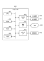
- FIG. 1 is a block diagram showing the configuration of a packet transfer control device according to the present embodiment.
- 3 is a flowchart showing the flow of processing executed by the packet transfer control device according to the present embodiment.
- FIG. 3 is a diagram illustrating an example data structure of flow information according to the present embodiment.
- FIG. 3 is a diagram illustrating an example data structure of simulation result information according to the present embodiment.
- FIG. 7 is a diagram illustrating another data configuration example of simulation result information according to the present embodiment. It is a block diagram showing the composition of the distribution simulation device concerning the modification of this embodiment.
- FIG. 2 is a hardware configuration diagram showing an example of a computer that implements the functions of the packet transfer control device according to the present embodiment.
- the packet transfer control device 1 acquires current flow information, simulates the load distribution situation while changing the hash key and hash calculation algorithm, and obtains the optimal simulation result (distribution result). It is characterized by selecting a hash key and a hash calculation algorithm and switching transfer processing. In addition, the packet transfer control device 1 acquires current flow information at predetermined time intervals and repeatedly simulates the load distribution situation, thereby dynamically switching transfer processing in response to band fluctuations for each flow. I do. Thereby, the packet transfer control device 1 can suppress the occurrence of band imbalance in distributed control on a per-flow basis.
- FIG. 1 is a block diagram showing the configuration of a packet transfer control device 1 according to this embodiment.
- the packet transfer control device 1 is realized by a computer including a control section, an input/output section, and a storage section (not shown).
- the packet transfer control device 1 also includes a distribution processing function configured by an ASIC 100 (Application Specific Integrated Circuit) and the like, and distributes packets to each flow.
- ASIC 100 Application Specific Integrated Circuit
- the input/output unit performs input/output of information between a communication device that is a packet input source and a plurality of communication devices that are packet output destinations.
- the packet transfer control device 1 is capable of distributing packets to a plurality of links (link #0, link #1, ...) provided between a plurality of communication devices that are output destinations of the packet, Based on the simulation results described later, links (link #0, link #1,%) through which each flow flows are selected so that the load is further distributed, that is, the occurrence of band imbalance is suppressed. Output the packet.
- This input/output unit consists of a communication interface that sends and receives information via a communication line, and an input/output interface that inputs and outputs information between an input device such as a keyboard and an output device such as a monitor (not shown). configured.
- the storage unit includes a hard disk, flash memory, RAM (Random Access Memory), and the like.
- This storage section temporarily stores programs for executing each function of the control section and information necessary for processing of the control section.
- This storage unit also contains information on links accommodating each flow, which is the result of simulation by combining hash keys and hash calculation algorithms (flow distribution results of simulation result information 300 in FIGS. 4 and 5, which will be described later). information) is stored.
- the control unit is in charge of overall processing executed by the packet transfer control device 1, and includes a traffic information acquisition unit 11, a distribution simulation unit 12, and a distribution algorithm switching controller 13, as shown in FIG.
- the traffic information acquisition unit 11 acquires traffic information from packets received from other communication devices at predetermined time intervals.
- the traffic information includes 5-tuple information (source IP address, source port number, destination IP address, destination port number, protocol number) and traffic amount information.
- the distribution simulation unit 12 acquires current flow information, simulates the load distribution situation while changing hash keys and hash calculation algorithms, and calculates links to which each flow is distributed. Then, the distribution simulation unit 12 selects a hash key and a hash calculation algorithm that result in an optimal simulation result among the simulation results, that is, distribution of flows with less bias in the bandwidth of each link.
- the distribution simulation section 12 includes a flow information acquisition section 121 , a hash key selection section 122 , a hash calculation algorithm selection section 123 , a simulation execution section 124 , and a distribution algorithm determination section 125 .
- the flow information acquisition unit 121 acquires flow information of each flow based on the traffic information acquired by the traffic information acquisition unit 11.
- the flow information acquired by the flow information acquisition unit 121 is, for example, 5-tuple information such as a source IP address (Src IP), a source port number (Src port), a destination IP address (Dst IP), Among the destination port number (Dst port), protocol number, etc., this includes information set in advance, and information on the bandwidth used for each flow.
- preset information which is information such as a 5-tuple and identifies a flow collected from a packet, is referred to as "packet collection information" in this embodiment.
- information on the bandwidth (width) used for each flow may be acquired by calculation by the flow information acquisition unit 121 based on the information on the traffic amount acquired by the traffic information acquisition unit 11, or The information acquisition unit 11 may calculate the bandwidth (width) to be used for each flow.
- the hash key selection unit 122 selects one from preset hash key candidates.
- the hash key selection unit 122 selects, for example, two-tuple information of a source IP address and a destination IP address, or selects three-tuple information of a source IP address, a destination IP address, and a source port number. .
- which set of information out of packet collection information such as 5-tuples is to be adopted as a hash key candidate is set in the hash key selection unit 122 in advance.
- the hash calculation algorithm selection unit 123 selects one hash calculation algorithm candidate from preset hash calculation algorithm candidates. Any hash calculation algorithm (for example, MD5, SHA-1, SHA-2, SHA-3) can be set as the preset hash calculation algorithm candidate. Further, a more detailed algorithm may be set as a hash calculation algorithm candidate. For example, settings such as ⁇ perform a remainder calculation on the 15th bit after an XOR (exclusive OR) operation'' and ⁇ perform a remainder calculation on the 16th bit after an XOR operation'' performed in a hash calculation are made.
- Any hash calculation algorithm for example, MD5, SHA-1, SHA-2, SHA-3
- a more detailed algorithm may be set as a hash calculation algorithm candidate. For example, settings such as ⁇ perform a remainder calculation on the 15th bit after an XOR (exclusive OR) operation'' and ⁇ perform a remainder calculation on the 16th bit after an XOR operation'' performed in a hash calculation are made.
- the simulation execution unit 124 performs hash calculation using the hash key candidate selected by the hash key selection unit 122 and the hash calculation algorithm candidate selected by the hash calculation algorithm selection unit 123, thereby determining the link to which the flow is distributed. Calculate (simulate). The simulation execution unit 124 executes a simulation for all combinations of the set hash key candidates and the set hash calculation algorithm candidates. Then, the simulation execution unit 124 stores flow distribution result information 300, which is the result of the simulation, in the storage unit (see FIGS. 4 and 5, which will be described later).
- the distribution algorithm determination unit 125 uses the flow distribution result information 300, which is the simulation result of the simulation execution unit 124, to select a “hash key” that best distributes the usage bandwidth of each link based on a predetermined algorithm determination logic. and "hash calculation algorithm”.
- This predetermined algorithm determination logic is, for example, the following logic.
- ⁇ Algorithm determination logic "1"> Among the links with the largest usage bandwidth among the links calculated for each pair of hash key candidate and hash calculation algorithm candidate, the link whose usage bandwidth is the smallest is calculated hash Select a pair of key candidates and hash calculation algorithm candidates. In other words, a combination of a "hash key” and a "hash calculation algorithm” with the minimum available bandwidth of the link where the traffic is most concentrated is selected.
- ⁇ Algorithm determination logic "2"> Calculates the variance of the usage bandwidth of each link, and selects the pair of "hash key” and "hash calculation algorithm” with the lowest variance value.
- the distribution algorithm determining unit 125 determines whether or not to perform a change process regarding link distribution (distribution algorithm change process) for the selected pair of "hash key" and "hash calculation algorithm”. Judgment is made based on judgment logic. For example, the predetermined change process determination logic executes the change process when the condition "the bandwidth used for each link is less than or equal to a predetermined threshold" is met, and on the other hand, the change process is executed when this condition is not met. The logic is not to execute it. In addition, the predetermined change process determination logic executes the change process when the condition "the distribution of the bandwidth used by each link is less than or equal to a predetermined threshold" is met; on the other hand, the change process is executed when this condition is not met. The logic may be that the process is not executed.
- the distribution algorithm determination unit 125 determines that the conditions based on the predetermined change process determination logic are satisfied, the distribution algorithm determination unit 125 uses information on the selected pair of "hash key” and "hash calculation algorithm” as a new distribution algorithm. Output to the distribution algorithm switching controller 13.
- the distribution algorithm switching controller 13 transfers the hash key and hash calculation algorithm switching information to a distribution processing function (here, , ASIC 100).
- the hash switching function unit 101 of the ASIC 100 switches the distribution algorithm based on the acquired "hash key” and "hash calculation algorithm” information. As a result, the ASIC 100 distributes and transfers the received packets to the newly set distribution destination links (links #0, #1, . . . ).
- this distribution processing function is not limited to the ASIC 100, and may be, for example, an FPGA (Field Programmable Gate Array).
- the packet transfer control device 1 is provided with a distribution processing function (switch) such as the ASIC 100; It may also be provided externally as a device in a separate housing.
- FIG. 2 is a flowchart showing the flow of processing executed by the packet transfer control device 1 according to the present embodiment.
- the traffic information acquisition unit 11 of the packet transfer control device 1 determines whether a predetermined time interval has elapsed (step S1). If the predetermined time has not elapsed (step S1 ⁇ No), the process returns to step S1. On the other hand, if the predetermined time has elapsed (step S1 ⁇ Yes), the process advances to step S2.
- step S2 the traffic information acquisition unit 11 acquires traffic information from packets received from other communication devices.
- This traffic information includes any one of preset information such as 5-tuples and information on the amount of traffic.
- the distribution simulation unit 12 acquires current flow information, simulates the load distribution situation while changing the hash key and hash calculation algorithm, and calculates the link to which each flow is distributed. Then, the distribution simulation unit 12 determines the pair of "hash key” and "hash calculation algorithm" for which the traffic is most distributed. Specifically, the following processing is executed.
- the flow information acquisition unit 121 of the distribution simulation unit 12 acquires flow information 200 of each flow based on the traffic information acquired by the traffic information acquisition unit 11 in step S2 (step S3).
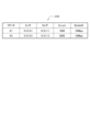
- FIG. 3 is a diagram illustrating an example data structure of the flow information 200 acquired by the flow information acquisition unit 121.
- the flow information 200 includes traffic information (packet collection information) set in advance from information such as 5-tuples in association with the flow ID (#1, #2) of each flow. and bandwidth information are stored.
- Figure 3 shows an example in which the source IP address (Src IP), destination IP address (Dst IP), and source port number (Src port) of the 5-tuple information are set as packet collection information. .
- packet collection information such as this 5-tuple that specifies this flow is used as a "hash key.”
- the hash key selection unit 112 of the distribution simulation unit 12 selects one from the preset hash key candidates (step S4).
- two hash key candidates shown below are set in advance, for example.
- Hash key candidate #1 ⁇ Src IP/Dst IP> ... (source IP address and destination IP address)
- hash key selection unit 112 selects hash key candidate #1.
- the hash calculation algorithm selection unit 123 of the distribution simulation unit 12 selects one from the preset hash calculation algorithm candidates (step S5).
- Hash calculation algorithm candidate #1 “Calculate the remainder on the 15th bit after the XOR operation”
- the hash calculation algorithm selection unit 123 selects hash calculation algorithm candidate #1.
- the simulation execution unit 124 of the distribution simulation unit 12 uses the hash key candidate selected by the hash key selection unit 122 in step S4 and the hash calculation algorithm candidate selected by the hash calculation algorithm selection unit 123 in step S5. , a simulation (hash calculation simulation) is executed to calculate a link to which the flow is to be distributed by hash calculation (step S6). Then, the simulation execution unit 124 stores the simulation result as simulation result information 300 in a storage unit (not shown).
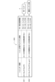
- FIG. 4 is a diagram showing an example data structure of simulation result information 300 generated by the simulation execution unit 124.
- the simulation result information 300 stores flow distribution result information in association with hash key candidates and hash calculation algorithm candidates.
- the hash key candidate is "#1: ⁇ Src IP/Dst IP>”
- the hash calculation algorithm candidate is "#1": "After It is shown that the following flow distribution result information was obtained as a simulation result when the 15th bit is subjected to a remainder calculation.
- Flow #2 Link #0
- This flow distribution result information indicates that it is a simulation result in which flow #1 is distributed to link #0 and flow #2 is distributed to link #0.
- step S7 determines whether any hash calculation algorithm candidates remain.
- step S7 ⁇ Yes the simulation execution unit 124 returns to step S5 and continues the process.
- step S7 ⁇ No the simulation execution unit 124 proceeds to the next step S8. Note that here, since there are no hash calculation algorithm candidates remaining, the process advances to step S8.
- step S8 determines whether there are any hash key candidates remaining.
- step S8 ⁇ Yes the simulation execution unit 124 returns to step S4 and continues the process.
- step S8 ⁇ No the simulation execution unit 124 proceeds to the next step S9.
- hash key candidate #2 since hash key candidate #2 remains, the process returns to step S4, and the processes from steps S4 to S8 are executed.
- the hash key candidate is "#2: ⁇ Src IP/Dst IP/Src port>" and the hash calculation algorithm candidate is “#1”:
- the following flow distribution result information is obtained as a simulation result when “perform the remainder on the 15th bit after the XOR operation”.
- Flow #1 Link #0
- Flow #2 Link #1 This flow distribution result information indicates that it is a simulation result in which flow #1 is distributed to link #0 and flow #2 is distributed to link #1.
- step S8 if there are no hash key candidates remaining (step S8 ⁇ No), the distribution algorithm determining unit 125 of the distribution simulation unit 12 selects the flow distribution result information of the simulation result information 400 (FIG. 4). , and selects a pair of "hash key” and "hash calculation algorithm” in which the usage bandwidth of each link is most distributed based on a predetermined algorithm determination logic (step S9).
- the distribution algorithm determining unit 125 uses the above-mentioned ⁇ algorithm determining logic "1"> as the predetermined algorithm determining logic, which is the "hash key” with the lowest bandwidth of the link where the most traffic is concentrated. It is assumed that "Select a set of hash calculation algorithms" has been set.
- flow #1 and flow #2 are the same link (represented by reference numeral a in FIG. 5), and on the other hand, in the simulation indicated by reference numeral 302, flow #1 and flow #2 are the same link. 2 is distributed over multiple links (labeled b in FIG. 5).
- the distribution algorithm determining unit 125 determines that the link with the most traffic concentration has the smallest available bandwidth (here, "100 (Mbps)"), that is, the link with the most traffic is distributed, code 302. Select the set of "hash key” and "hash calculation algorithm” for the simulation shown in .
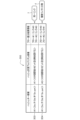
- FIG. 5 is a diagram showing another data configuration example of the simulation result information 300 generated by the simulation execution unit 124.
- one hash key candidate and two hash calculation algorithm candidates are set in advance, and the simulation execution unit 124 shows the result of executing the hash calculation simulation in step S6.
- the hash key candidate is "#1: ⁇ Src IP/Dst IP/Src port>" and the hash calculation algorithm candidate is "#1":” It is shown that the following flow distribution result information was obtained as a simulation result when the 16th bit is subjected to a remainder calculation after the XOR operation.
- Flow #2: Link #0 This flow distribution result information indicates that flow #1 is distributed to link #0 and flow #2 is distributed to link #0, that is, it is a simulation result in which flow #2 is distributed to the same link (reference numeral c in FIG. 5).
- the hash key candidate is "#1: ⁇ Src IP/Dst IP/Src port>" and the hash calculation algorithm candidate is "#2". : It is shown that the following flow distribution result information was obtained as a simulation result when ⁇ perform the remainder on the 15th bit after the XOR operation''.
- Flow #1 Link #0
- Flow #2 Link #1 This flow distribution result information indicates that flow #1 is distributed to link #0 and flow #2 is distributed to link #1, that is, it is a simulation result that is distributed over multiple links (reference d in Figure 5). ).
- the distribution simulation unit 12 executes a hash calculation simulation for all preset combinations of hash key candidates and distribution algorithm candidates, and selects the "hash Select a pair of "key” and "hash calculation algorithm”.
- the distribution algorithm determining unit 125 determines whether or not to perform a distribution algorithm change process based on a predetermined change process determination logic (step S10).
- the predetermined change process determination logic is, for example, "If the condition that the usage bandwidth of each link is equal to or less than a predetermined threshold is satisfied, the change process is executed."
- the distribution algorithm determining unit 125 selects, for example, the flow distribution result information of the set of "hash key” and "hash calculation algorithm" of the simulation indicated by reference numeral 302 in FIG. It is determined whether the bandwidth used by flow #1 (100 Mbps) and the bandwidth used by flow #2 (100 Mbps) are less than or equal to a predetermined threshold.
- the distribution algorithm determining unit 125 determines that the condition based on the predetermined change processing determination logic is satisfied (step S10 ⁇ Yes), and proceeds to the next step S11. .
- the distribution algorithm determining unit 125 outputs information on the selected pair of "hash key” and "hash calculation algorithm” to the distribution algorithm switching controller 13.
- the distribution algorithm determining unit 125 determines that the condition based on the predetermined change process determination logic is not satisfied (step S10 ⁇ No), and performs the change process of the distribution algorithm. The process returns to step S1 without performing this step.
- step S11 the distribution algorithm switching controller 13 distributes the hash key and hash calculation algorithm switching information based on the acquired information on the set of "hash key” and "hash calculation algorithm” (distribution algorithm). function (here, ASIC 100). As a result, the hash switching function unit 101 of the ASIC 100 changes the distribution algorithm.
- the packet transfer control device 1 dynamically switches transfer processing in response to band fluctuations for each flow by repeating the simulation of this load distribution situation at predetermined time intervals. Therefore, the packet transfer control device 1 can suppress the occurrence of band imbalance in distributed control on a per-flow basis.
- the distribution simulation device 2 shown in FIG. 6 includes the functions of a flow information acquisition section 121, a hash key selection section 112, a hash calculation algorithm selection section 123, a simulation execution section 124, and a distribution algorithm determination section 125 shown in FIG. . Thereby, by inputting arbitrary flow information, the distribution simulation device 2 simulates and outputs information on links to which each flow is distributed.
- the packet transfer control device 1 is realized, for example, by a computer 900 having a configuration as shown in FIG.
- FIG. 7 is a hardware configuration diagram showing an example of a computer 900 that implements the functions of the packet transfer control device 1 according to the present embodiment.
- the computer 900 includes a CPU (Central Processing Unit) 901, a ROM (Read Only Memory) 902, a RAM 903, an HDD (Hard Disk Drive) 904, an input/output I/F (Interface) 905, a communication I/F 906, and a media I/F 907.
- a CPU Central Processing Unit
- ROM Read Only Memory
- RAM 903 Random Access Memory
- HDD Hard Disk Drive
- I/F Interface
- the CPU 901 operates based on a program stored in the ROM 902 or HDD 904, and controls each functional unit shown in FIG.
- the ROM 902 stores a boot program executed by the CPU 901 when the computer 900 is started, programs related to the hardware of the computer 900, and the like.
- the CPU 901 controls an input device 910 such as a mouse or a keyboard, and an output device 911 such as a display or printer via an input/output I/F 905.
- the CPU 901 acquires data from the input device 910 via the input/output I/F 905 and outputs the generated data to the output device 911.
- the packet transfer control device 1 includes a distribution processing function such as the ASIC 100 (see FIG. 1), information is transmitted and received via the input/output I/F 905.
- the HDD 904 stores programs executed by the CPU 901 and data used by the programs.
- the communication I/F 906 receives data from other devices via a communication network (for example, NW (Network) 920) and outputs it to the CPU 901, and also sends data generated by the CPU 901 to other devices via the communication network. Send to device.
- NW Network
- the media I/F 907 reads the program or data stored in the recording medium 912 and outputs it to the CPU 901 via the RAM 903.
- the CPU 901 loads a program related to target processing from the recording medium 912 onto the RAM 903 via the media I/F 907, and executes the loaded program.
- the recording medium 912 is an optical recording medium such as a DVD (Digital Versatile Disc) or a PD (Phase change rewritable disk), a magneto-optical recording medium such as an MO (Magneto Optical disk), a magnetic recording medium, a semiconductor memory, or the like.
- the CPU 901 of the computer 900 realizes the functions of the packet transfer control device 1 by executing a program loaded onto the RAM 903. Furthermore, data in the RAM 903 is stored in the HDD 904 .
- the CPU 901 reads a program related to target processing from the recording medium 912 and executes it. In addition, the CPU 901 may read a program related to target processing from another device via a communication network (NW 920).
- the packet transfer control device is a packet transfer control device 1 that controls switching to each link in packet transfer processing, and includes packet collection information that is collected from packets and includes information that identifies a flow, and
- the flow information acquisition unit 121 acquires flow information including information on the band used by the flow, and packet collection information is used to select one from preset hash key candidates.
- a simulation execution unit 124 that executes a simulation for calculating links to which flows are to be distributed for all combinations of hash key candidates and hash calculation algorithm candidates, and hash key candidates and hash calculation algorithm candidates obtained as a result of the simulation. Based on the information on the links to which the flow is distributed, the bandwidth usage of each link is calculated using the flow bandwidth information, and based on a predetermined algorithm decision logic, the usage bandwidth of each link is determined to be the most distributed.
- a distribution algorithm determining unit 125 that selects a set of a hash key candidate and a hash calculation algorithm candidate, and outputs information on the set of the selected hash key candidate and hash calculation algorithm candidate, and the selected hash key candidate.
- a distribution algorithm switching controller 13 that acquires information on a set of hash calculation algorithm candidates and transmits the information to a distribution processing function that distributes the packet to each link, thereby switching the setting of the link to which the packet is distributed; It is characterized by having the following.
- the packet transfer control device 1 executes a simulation to calculate links to which flows are to be distributed for all combinations of hash key candidates and hash calculation algorithm candidates, and calculates the most distributed bandwidth of each link.
- a combination of a hash key and a hash calculation algorithm can be selected.
- the packet transfer control device 1 can suppress the occurrence of imbalance in the bandwidth of each link.
- the packet transfer control device 1 can realize optimal flow load distribution in response to band fluctuations of each flow.
- the predetermined algorithm determination logic selects a link with the largest used bandwidth among the links calculated for each pair of hash key candidates and hash calculation algorithm candidates. It is characterized by a logic that selects a set of a hash key candidate and a hash calculation algorithm candidate for which a link is calculated.
- the packet transfer control device 1 can distribute the usage bandwidth of each link and reliably suppress the occurrence of band imbalance.
- the predetermined algorithm determination logic calculates the variance of the usage bandwidth of each link for each pair of hash key candidates and hash calculation algorithm candidates, and selects the hash key candidate with the lowest variance value. and a logic for selecting a set of hash calculation algorithm candidates.
- the packet transfer control device 1 can distribute the usage bandwidth of each link and reliably suppress the occurrence of band imbalance.
- the distribution simulation device 2 includes a flow information acquisition unit 121 that acquires packet collection information that is collected from packets and includes information that identifies a flow, and flow information that includes information on the band used by the flow. , is information configured using packet collection information, and hash key selection unit 122 selects one from preset hash key candidates, and selects one from preset hash calculation algorithm candidates. Using the selected hash calculation algorithm selection unit 123 and the selected hash calculation algorithm candidate, a simulation is performed to calculate a link to which a flow is to be distributed using the selected hash calculation algorithm candidate and the hash calculation algorithm candidate.
- the simulation execution unit 124 executes the simulation execution unit 124 for all combinations of The information is used to calculate the bandwidth usage of each link, and based on a predetermined algorithm decision logic, a pair of hash key candidates and hash calculation algorithm candidates that has the most distributed bandwidth usage of each link is selected. It is characterized by comprising a distribution algorithm determining unit 125 that outputs information on a set of a hash key candidate and a hash calculation algorithm candidate.
- the distribution simulation device 2 can quickly determine which link the relevant path passes through based on flow information or the like.
- Packet transfer control device 2 Distribution simulation device 11 Traffic information acquisition section 12 Distribution simulation section 13 Distribution algorithm switching controller 100 ASIC (distribution processing function) 101 hash switching function unit 121 flow information acquisition unit 122 hash key selection unit 123 hash calculation algorithm selection unit 124 simulation execution unit 125 distribution algorithm determination unit 200 flow information 300 simulation result information
Landscapes
- Engineering & Computer Science (AREA)
- Computer Networks & Wireless Communication (AREA)
- Signal Processing (AREA)
- Data Exchanges In Wide-Area Networks (AREA)
Abstract
パケット転送制御装置(1)は、パケット収集情報およびフローが利用する帯域を含むフロー情報を取得するフロー情報取得部(121)と、選択されたハッシュキー候補を用いて、選択されたハッシュ計算アルゴリズム候補により、フローの振り分け先となるリンクを算出するシミュレーションを、ハッシュキー候補およびハッシュ計算アルゴリズム候補のすべての組合せについて実行するシミュレーション実行部(124)と、各リンクの利用帯域が最も分散している、ハッシュキー候補とハッシュ計算アルゴリズム候補の組を選択する振分アルゴリズム決定部(125)と、選択された組の情報を振分処置機能に送信して設定させる振分アルゴリズム切替コントローラ(13)と、を備える。
Description
本発明は、パケットの分散制御を実現する、パケット転送制御装置、パケット転送制御方法、振分シミュレーション装置、および、プログラムに関する。
データセンタ内のパケット転送アーキテクチャでは、例えば、リーフ&スパイン型を採用し、安全性確保や負荷分散のための冗長構成を構築している。リーフスイッチは、複数のスパインスイッチの一つを選択して、データパケットを転送する。その際、どのスパインスイッチを選択するかは、負荷分散のアルゴリズムに依存し、フロー単位での分散や、パケット単位での分散が既存技術として知られている。
フロー単位での分散では、特定のサービスに属する、送信元IPアドレスや宛先IPアドレスを同一とするパケット群を、フローとしてまとめて(フロー単位で)の分散を行う。分散時の帯域情報などをもとにパスを動的に選択することで、帯域の偏りを生じさせないようにすることができる(非特許文献1参照)一方、パケット単位で分散を行うことにより、フロー単位よりも帯域の偏りを生じさせないようにすることができる(非特許文献2参照)。
Tat Wing Chim, et al.,"Traffic Distribution over Equal-Cost-Multi-Paths,"IEEE Communications Society 2004
Jiawei Huang,et al.,"QDAPS: Queueing Delay Aware Packet Spraying for Load Balancing in Data Center,"2018 IEEE DOI 10.1109/ICNP.2018.000017
フロー単位のL3(Layer 3)ルーティングにおけるECMP(Equal Cost Multi Path:等コストマルチパス)や、リンクアグリゲーションでは、フロー毎に得られる5タプル等の計算パラメータのハッシュ値を計算することにより負荷分散している。しかしながら、このような従来の静的なハッシュに従ったフロー単位の分散では、特定のフローの帯域が大きい場合や、多段でハッシュをかける場合において、帯域の偏りが生じる場合がある。なお、多段でハッシュかける場合では、多段接続で同じロードバランス手法(ハッシュ計算アルゴリズム)を採用すると後続のルータで同じ値が算出され、ロードバランスしないケースが生じることがある。
また、フロー単位の分散において、分散時の帯域情報などをもとにパスを動的に選択する技術もあるが、その場合には、フロー毎に選択したパス情報を保持する等の追加となる処理(状態管理)が必要となる。
一方、パケット単位での負荷分散では、パケットの到着順序の逆転や、障害時の影響が全フローに波及してしまうという問題があり、セル単位の分散では、フロー単位やパケット単位とは異なる転送方式を新たに導入しなければならないという問題があった。
一方、パケット単位での負荷分散では、パケットの到着順序の逆転や、障害時の影響が全フローに波及してしまうという問題があり、セル単位の分散では、フロー単位やパケット単位とは異なる転送方式を新たに導入しなければならないという問題があった。
このような点を鑑みて本発明がなされたのであり、本発明は、パケットの負荷分散制御において、帯域の偏りの発生を抑制することを課題とする。
本発明に係るパケット転送制御装置は、パケットの転送処理における各リンクへの切り替えを制御するパケット転送制御装置であって、前記パケットから収集されフローを特定する情報を含むパケット収集情報、および、当該フローが利用する帯域の情報、を含むフロー情報を取得するフロー情報取得部と、前記パケット収集情報を用いて構成される情報であり、予め設定されるハッシュキー候補の中から1つを選択するハッシュキー選択部と、予め設定されたハッシュ計算アルゴリズム候補の中から1つを選択するハッシュ計算アルゴリズム選択部と、選択された前記ハッシュキー候補を用いて、選択された前記ハッシュ計算アルゴリズム候補により、前記フローの振り分け先となるリンクを算出するシミュレーションを、前記ハッシュキー候補および前記ハッシュ計算アルゴリズム候補のすべての組合せについて実行するシミュレーション実行部と、前記シミュレーションの結果として得られた、前記ハッシュキー候補および前記ハッシュ計算アルゴリズム候補に応じた、前記フローの振り分け先となるリンクの情報の中から、前記フローの帯域の情報を用いて各リンクの利用帯域を算出し、所定のアルゴリズム決定ロジックに基づき、各リンクの利用帯域が最も分散している、前記ハッシュキー候補と前記ハッシュ計算アルゴリズム候補の組を選択し、選択された前記ハッシュキー候補と前記ハッシュ計算アルゴリズム候補の組の情報を出力する振分アルゴリズム決定部と、選択された前記ハッシュキー候補と前記ハッシュ計算アルゴリズム候補の組の情報を取得して、前記パケットを各リンクへ振り分ける振分処置機能に送信することにより、前記パケットの振り分け先となるリンクの設定を切り替えさせる振分アルゴリズム切替コントローラと、を備えることを特徴とする。
本発明に係るパケット転送制御装置は、パケットの負荷分散制御において、帯域の偏りの発生を抑制することができる。
次に、本発明を実施するための形態(以下、「本実施形態」と称する。)について説明する。
本実施形態に係るパケット転送制御装置1は、現時点のフロー情報を取得し、ハッシュキーやハッシュ計算アルゴリズムを変更しながら負荷分散状況をシミュレーションし、最適なシミュレーションの結果(振分結果)となったハッシュキーおよびハッシュ計算アルゴリズムを選択し、転送処理の切り替えを行うことを特徴とする。また、パケット転送制御装置1は、所定時間ごとに、その時点のフロー情報を取得し、負荷分散状況のシミュレーションを繰り返すことにより、フローごとの帯域の変動に対応して動的に転送処理の切り替えを行う。これにより、パケット転送制御装置1は、フロー単位の分散制御において、帯域の偏りの発生を抑制することができる。
本実施形態に係るパケット転送制御装置1は、現時点のフロー情報を取得し、ハッシュキーやハッシュ計算アルゴリズムを変更しながら負荷分散状況をシミュレーションし、最適なシミュレーションの結果(振分結果)となったハッシュキーおよびハッシュ計算アルゴリズムを選択し、転送処理の切り替えを行うことを特徴とする。また、パケット転送制御装置1は、所定時間ごとに、その時点のフロー情報を取得し、負荷分散状況のシミュレーションを繰り返すことにより、フローごとの帯域の変動に対応して動的に転送処理の切り替えを行う。これにより、パケット転送制御装置1は、フロー単位の分散制御において、帯域の偏りの発生を抑制することができる。
図1は、本実施形態に係るパケット転送制御装置1の構成を示すブロック図である。
パケット転送制御装置1は、図示を省略した、制御部、入出力部および記憶部を備えるコンピュータにより実現される。また、パケット転送制御装置1は、ASIC100(Application Specific Integrated Circuit:特定用途向け集積回路)等により構成される振分処理機能を備え、パケットの各フローへの振り分けが行われる。
パケット転送制御装置1は、図示を省略した、制御部、入出力部および記憶部を備えるコンピュータにより実現される。また、パケット転送制御装置1は、ASIC100(Application Specific Integrated Circuit:特定用途向け集積回路)等により構成される振分処理機能を備え、パケットの各フローへの振り分けが行われる。
入出力部は、パケットの入力元となる通信装置や、パケットの出力先となる複数の通信装置との間の情報について入出力を行う。なお、パケット転送制御装置1は、パケットの出力先となる複数の通信装置との間に設けられた複数のリンク(リンク#0,リンク#1,…)にパケットを振り分けることが可能であり、後記するシミュレーション結果に基づき、より負荷分散されるように、つまり、帯域の偏りの発生が抑制されるように、各フローを流すリンク(リンク#0,リンク#1,…)を選択して、パケットを出力する。
この入出力部は、通信回線を介して情報の送受信を行う通信インタフェースと、図示を省略したキーボード等の入力装置やモニタ等の出力装置との間で情報の入出力を行う入出力インタフェースとから構成される。
この入出力部は、通信回線を介して情報の送受信を行う通信インタフェースと、図示を省略したキーボード等の入力装置やモニタ等の出力装置との間で情報の入出力を行う入出力インタフェースとから構成される。
記憶部は、ハードディスクやフラッシュメモリ、RAM(Random Access Memory)等により構成される。
この記憶部には、制御部の各機能を実行させるためのプログラムや、制御部の処理に必要な情報が一時的に記憶される。また、この記憶部には、ハッシュキーとハッシュ計算アルゴリズムとを組み合わせてシミュレーションした結果である、各フローを収容するリンクの情報(後記する図4,図5のシミュレーション結果情報300のフロー振分結果情報)が格納される。
この記憶部には、制御部の各機能を実行させるためのプログラムや、制御部の処理に必要な情報が一時的に記憶される。また、この記憶部には、ハッシュキーとハッシュ計算アルゴリズムとを組み合わせてシミュレーションした結果である、各フローを収容するリンクの情報(後記する図4,図5のシミュレーション結果情報300のフロー振分結果情報)が格納される。
制御部は、パケット転送制御装置1が実行する処理の全般を司り、図1で示すように、トラヒック情報取得部11と、振分シミュレーション部12と、振分アルゴリズム切替コントローラ13とを備える。
トラヒック情報取得部11は、所定の時間間隔ごとに、他の通信装置から受信したパケットからトラヒック情報を取得する。
トラヒック情報の中には、5タプル(5tuple)の情報(送信元IPアドレス、送信元ポート番号、宛先IPアドレス、宛先ポート番号、プロトコル番号)や、トラヒック量の情報が含まれる。
トラヒック情報の中には、5タプル(5tuple)の情報(送信元IPアドレス、送信元ポート番号、宛先IPアドレス、宛先ポート番号、プロトコル番号)や、トラヒック量の情報が含まれる。
振分シミュレーション部12は、現時点のフロー情報を取得し、ハッシュキーやハッシュ計算アルゴリズムを変更しながら負荷分散状況をシミュレーションし、各フローの振り分け先となるリンクを算出する。そして、振分シミュレーション部12は、シミュレーション結果のうちの最適なシミュレーションの結果、つまり、各リンクの帯域の偏りが少ないフローの振り分けとなる、ハッシュキーおよびハッシュ計算アルゴリズムを選択する。
この振分シミュレーション部12は、フロー情報取得部121、ハッシュキー選択部122、ハッシュ計算アルゴリズム選択部123、シミュレーション実行部124および振分アルゴリズム決定部125を備える。
この振分シミュレーション部12は、フロー情報取得部121、ハッシュキー選択部122、ハッシュ計算アルゴリズム選択部123、シミュレーション実行部124および振分アルゴリズム決定部125を備える。
フロー情報取得部121は、トラヒック情報取得部11が取得したトラヒック情報に基づき、各フローのフロー情報を取得する。ここで、フロー情報取得部121が取得するフロー情報は、例えば、5タプルの情報である、送信元IPアドレス(Src IP)、送信元ポート番号(Src port)、宛先IPアドレス(Dst IP)、宛先ポート番号(Dst port)、プロトコル番号等の中で、予め設定した情報と、フローごとに利用する帯域(幅)(Bandwidth)の情報である。なお、5タプル等の情報であり、パケットから収集されたフローと特定する情報のうち、予め設定された情報を本実施形態では「パケット収集情報」と称する。また、フローごとに利用する帯域(幅)の情報は、トラヒック情報取得部11が取得したトラヒック量の情報等に基づき、フロー情報取得部121が算出すること等により取得してもよいし、トラヒック情報取得部11が、フローごとに利用する帯域(幅)を算出するようにしてもよい。
ハッシュキー選択部122は、予め設定されたハッシュキー候補の中から1つを選択する。ハッシュキー選択部122は、例えば、送信元IPアドレスおよび宛先IPアドレスの2つタプル情報を選択したり、送信元IPアドレス、宛先IPアドレスおよび送信元ポート番号の3つのタプル情報を選択したりする。
例えば5タプル等のパケット収集情報のうちのどの情報の組を、ハッシュキー候補として採用するかは、予めハッシュキー選択部122に設定される。
例えば5タプル等のパケット収集情報のうちのどの情報の組を、ハッシュキー候補として採用するかは、予めハッシュキー選択部122に設定される。
ハッシュ計算アルゴリズム選択部123は、予め設定されたハッシュ計算アルゴリズム候補の中から、1つのハッシュ計算アルゴリズム候補を選択する。
予め設定されるハッシュ計算アルゴリズム候補は、任意のハッシュ計算アルゴリズム(例えば、MD5,SHA-1,SHA-2,SHA-3)を設定することができる。また、ハッシュ計算アルゴリズム候補として、より詳細なアルゴリズムを設定してもよい。例えば、ハッシュ計算において行われる「XOR(排他的論理和)演算後の15ビット目を剰余算する」「XOR演算後の16ビット目を剰余算する」等の設定しておく。
予め設定されるハッシュ計算アルゴリズム候補は、任意のハッシュ計算アルゴリズム(例えば、MD5,SHA-1,SHA-2,SHA-3)を設定することができる。また、ハッシュ計算アルゴリズム候補として、より詳細なアルゴリズムを設定してもよい。例えば、ハッシュ計算において行われる「XOR(排他的論理和)演算後の15ビット目を剰余算する」「XOR演算後の16ビット目を剰余算する」等の設定しておく。
シミュレーション実行部124は、ハッシュキー選択部122が選択したハッシュキー候補を用いて、ハッシュ計算アルゴリズム選択部123が選択したハッシュ計算アルゴリズム候補により、ハッシュ計算することにより、そのフローの振り分け先となるリンクを算出(シミュレーション)する。シミュレーション実行部124は、設定されたハッシュキー候補と、設定されたハッシュ計算アルゴリズム候補についてのすべての組合せについてシミュレーションを実行する。
そして、シミュレーション実行部124は、そのシミュレーションの結果である、フロー振分結果情報300を記憶部に格納する(後記する図4,図5参照)。
そして、シミュレーション実行部124は、そのシミュレーションの結果である、フロー振分結果情報300を記憶部に格納する(後記する図4,図5参照)。
振分アルゴリズム決定部125は、シミュレーション実行部124のシミュレーション結果であるフロー振分結果情報300を用いて、所定のアルゴリズム決定ロジックに基づき、最も各リンクの利用帯域が分散されている「ハッシュキー」と「ハッシュ計算アルゴリズム」の組を選択する。
この所定のアルゴリズム決定ロジックは、例えば、以下のロジックである。
<アルゴリズム決定ロジック「1」>ハッシュキー候補とハッシュ計算アルゴリズム候補の組それぞれで算出された各リンクの中で最も利用帯域が大きいリンクのうち、当該利用帯域が最小となるリンクが算出されたハッシュキー候補とハッシュ計算アルゴリズム候補の組を選択する。つまり、最もトラヒックの集中しているリンクの利用帯域が最小の「ハッシュキー」と「ハッシュ計算アルゴリズム」の組を選択する。
<アルゴリズム決定ロジック「2」>各リンクの利用帯域の分散を算出し、最も分散の値が低い「ハッシュキー」と「ハッシュ計算アルゴリズム」の組を選択する。
<アルゴリズム決定ロジック「1」>ハッシュキー候補とハッシュ計算アルゴリズム候補の組それぞれで算出された各リンクの中で最も利用帯域が大きいリンクのうち、当該利用帯域が最小となるリンクが算出されたハッシュキー候補とハッシュ計算アルゴリズム候補の組を選択する。つまり、最もトラヒックの集中しているリンクの利用帯域が最小の「ハッシュキー」と「ハッシュ計算アルゴリズム」の組を選択する。
<アルゴリズム決定ロジック「2」>各リンクの利用帯域の分散を算出し、最も分散の値が低い「ハッシュキー」と「ハッシュ計算アルゴリズム」の組を選択する。
そして、振分アルゴリズム決定部125は、選択した「ハッシュキー」と「ハッシュ計算アルゴリズム」の組について、リンクの振り分けに関する変更処理(振分アルゴリズム変更処理)を行うか否かを、所定の変更処理判定ロジックに基づき判定する。
所定の変更処理判定ロジックは、例えば、「各リンクの利用帯域が所定の閾値以下であること」の条件を満たす場合に変更処理を実行する、一方、この条件を満たさない場合には変更処理を実行しない、というロジックである。また、所定の変更処理判定ロジックは、「各リンクの利用帯域の分散が、所定の閾値以下である」の条件を満たす場合に変更処理を実行する、一方、この条件を満たさない場合には変更処理を実行しない、というロジックでもよい。
所定の変更処理判定ロジックは、例えば、「各リンクの利用帯域が所定の閾値以下であること」の条件を満たす場合に変更処理を実行する、一方、この条件を満たさない場合には変更処理を実行しない、というロジックである。また、所定の変更処理判定ロジックは、「各リンクの利用帯域の分散が、所定の閾値以下である」の条件を満たす場合に変更処理を実行する、一方、この条件を満たさない場合には変更処理を実行しない、というロジックでもよい。
振分アルゴリズム決定部125は、所定の変更処理判定ロジックに基づく条件を満たすと判定した場合には、選択した「ハッシュキー」と「ハッシュ計算アルゴリズム」の組の情報を新たな振分アリゴリズムとして、振分アルゴリズム切替コントローラ13へ出力する。
振分アルゴリズム切替コントローラ13は、取得した「ハッシュキー」と「ハッシュ計算アルゴリズム」の組みの情報(振分アルゴリズム)に基づき、ハッシュキーとハッシュ計算アルゴリズムの切り替え情報を、振分処理機能(ここでは、ASIC100)に送信する。
ASIC100のハッシュ切替機能部101は、取得した「ハッシュキー」と「ハッシュ計算アルゴリズム」の情報に、振分アルゴリズムを切り替える。これにより、ASIC100は、受信したパケットを、新たに設定した振分先のリンク(リンク#0,#1,…)に振り分けて転送する。
なお、この振分処理機能は、ASIC100に限定されず、例えば、FPGA(Field Programmable Gate Array)等であってもよい。
また、図1においては、ASIC100等の振分処理機能(スイッチ)を、パケット転送制御装置1の内部に備えるものとしたが、パケット転送制御装置1を、ASIC100等の振分処理機能(スイッチ)とは別筐体の装置として外部に設けてもよい。
なお、この振分処理機能は、ASIC100に限定されず、例えば、FPGA(Field Programmable Gate Array)等であってもよい。
また、図1においては、ASIC100等の振分処理機能(スイッチ)を、パケット転送制御装置1の内部に備えるものとしたが、パケット転送制御装置1を、ASIC100等の振分処理機能(スイッチ)とは別筐体の装置として外部に設けてもよい。
<パケット転送制御装置の処理>
次に、パケット転送制御装置1が実行する処理の流れについて説明する。
図2は、本実施形態に係るパケット転送制御装置1が実行する処理の流れを示すフローチャートである。
次に、パケット転送制御装置1が実行する処理の流れについて説明する。
図2は、本実施形態に係るパケット転送制御装置1が実行する処理の流れを示すフローチャートである。
まず、パケット転送制御装置1のトラヒック情報取得部11は、所定の時間間隔が経過したか否かを判定する(ステップS1)。所定の時間が経過していなければ(ステップS1→No)、ステップS1に戻る。一方、所定の時間が経過した場合には(ステップS1→Yes)、ステップS2へ進む。
ステップS2において、トラヒック情報取得部11は、他の通信装置から受信したパケットからトラヒック情報を取得する。このトラヒック情報には、予め設定された5タプル等の情報うちのいずれかの情報や、トラヒック量の情報が含まれる。
次に、振分シミュレーション部12は、現時点のフロー情報を取得し、ハッシュキーやハッシュ計算アルゴリズムを変更しながら負荷分散状況をシミュレーションし、各フローの振り分け先となるリンクを算出する。そして、振分シミュレーション部12は、最もトラヒックが分散されている「ハッシュキー」と「ハッシュ計算アルゴリズム」の組を決定する。具体的には、以下の処理を実行する。
まず、振分シミュレーション部12のフロー情報取得部121は、ステップS2において、トラヒック情報取得部11が取得したトラヒック情報に基づき、各フローのフロー情報200を取得する(ステップS3)。
図3は、フロー情報取得部121が取得したフロー情報200のデータ構成例を示す図である。
図3で示すように、フロー情報200には、各フローのフローID(#1,#2)に対応付けて、予め5タプル等の情報のうちから設定されたトラヒックの情報(パケット収集情報)と帯域(幅)(Bandwidth)の情報が格納される。図3においては、5タプルの情報うちの、送信元IPアドレス(Src IP)、宛先IPアドレス(Dst IP)、送信元ポート番号(Src port)がパケット収集情報として設定される例を示している。なお、このフローを特定するこの5タプル等のパケット収集情報が、「ハッシュキー」として用いられる。
図3で示すように、フロー情報200には、各フローのフローID(#1,#2)に対応付けて、予め5タプル等の情報のうちから設定されたトラヒックの情報(パケット収集情報)と帯域(幅)(Bandwidth)の情報が格納される。図3においては、5タプルの情報うちの、送信元IPアドレス(Src IP)、宛先IPアドレス(Dst IP)、送信元ポート番号(Src port)がパケット収集情報として設定される例を示している。なお、このフローを特定するこの5タプル等のパケット収集情報が、「ハッシュキー」として用いられる。
次に、振分シミュレーション部12のハッシュキー選択部112は、予め設定されたハッシュキー候補の中から1つを選択する(ステップS4)。
ここでは、例えば、以下に示す、2つのハッシュキー候補が予め設定されているものとする。
ハッシュキー候補#1:<Src IP/Dst IP> …(送信元IPアドレスおよび宛先IPアドレス)
ハッシュキー候補#2:<Src IP/Dst IP/Src port> …(送信元IPアドレス、宛先IPアドレスおよび送信元ポート番号)
そして、ここでは、ハッシュキー選択部112は、ハッシュキー候補#1を選択したものとして、以下において説明する。
ここでは、例えば、以下に示す、2つのハッシュキー候補が予め設定されているものとする。
ハッシュキー候補#1:<Src IP/Dst IP> …(送信元IPアドレスおよび宛先IPアドレス)
ハッシュキー候補#2:<Src IP/Dst IP/Src port> …(送信元IPアドレス、宛先IPアドレスおよび送信元ポート番号)
そして、ここでは、ハッシュキー選択部112は、ハッシュキー候補#1を選択したものとして、以下において説明する。
続いて、振分シミュレーション部12のハッシュ計算アルゴリズム選択部123は、予め設定されたハッシュ計算アルゴリズム候補の中から1つを選択する(ステップS5)。
ここでは、例えば、以下に示す1つのハッシュ計算アルゴリズム候補が設定されているものとする。
ハッシュ計算アルゴリズム候補#1:「XOR演算後15ビット目を剰余算する」
そして、ここでハッシュ計算アルゴリズム選択部123は、ハッシュ計算アルゴリズム候補#1を選択する。
ここでは、例えば、以下に示す1つのハッシュ計算アルゴリズム候補が設定されているものとする。
ハッシュ計算アルゴリズム候補#1:「XOR演算後15ビット目を剰余算する」
そして、ここでハッシュ計算アルゴリズム選択部123は、ハッシュ計算アルゴリズム候補#1を選択する。
次に、振分シミュレーション部12のシミュレーション実行部124は、ステップS4においてハッシュキー選択部122が選択したハッシュキー候補を用いて、ステップS5においてハッシュ計算アルゴリズム選択部123が選択したハッシュ計算アルゴリズム候補により、ハッシュ計算することにより、そのフローの振り分け先となるリンクを算出するシミュレーション(ハッシュ計算シミュレーション)を実行する(ステップS6)。
そして、シミュレーション実行部124は、そのシミュレーション結果を、シミュレーション結果情報300として、図示を省略した記憶部に格納する。
そして、シミュレーション実行部124は、そのシミュレーション結果を、シミュレーション結果情報300として、図示を省略した記憶部に格納する。
図4は、シミュレーション実行部124が生成したシミュレーション結果情報300のデータ構成例を示す図である。
図4で示すように、シミュレーション結果情報300には、ハッシュキー候補およびハッシュ計算アルゴリズム候補に対応付けてフロー振分結果情報が格納される。
図4のシミュレーション結果情報300の1行目(符号301)では、ハッシュキー候補が「#1:<Src IP/Dst IP>」であり、ハッシュ計算アルゴリズム候補が「#1」:「XOR演算後15ビット目を剰余算する」であるときのシミュレーション結果として、以下のフロー振分結果情報が得られたことを示している。
フロー#1:リンク#0
フロー#2:リンク#0
このフロー振分結果情報は、フロー#1をリンク#0に振り分け、フロー#2をリンク#0に振り分けるシミュレーション結果であることを示している。
図4で示すように、シミュレーション結果情報300には、ハッシュキー候補およびハッシュ計算アルゴリズム候補に対応付けてフロー振分結果情報が格納される。
図4のシミュレーション結果情報300の1行目(符号301)では、ハッシュキー候補が「#1:<Src IP/Dst IP>」であり、ハッシュ計算アルゴリズム候補が「#1」:「XOR演算後15ビット目を剰余算する」であるときのシミュレーション結果として、以下のフロー振分結果情報が得られたことを示している。
フロー#1:リンク#0
フロー#2:リンク#0
このフロー振分結果情報は、フロー#1をリンク#0に振り分け、フロー#2をリンク#0に振り分けるシミュレーション結果であることを示している。
続いて、シミュレーション実行部124は、ハッシュ計算アルゴリズム候補が残っているか否かを判定する(ステップS7)。ここで、シミュレーション実行部124は、選択していないハッシュ計算アルゴリズム候補が残っていれば(ステップS7→Yes)、ステップS5に戻り、処理を続ける。一方、シミュレーション実行部124は、選択していないハッシュ計算アルゴリズム候補が残っていなければ(ステップS7→No)、次のステップS8へ進む。
なお、ここでは、ハッシュ計算アルゴリズム候補が残っていないので、ステップS8へ進む。
なお、ここでは、ハッシュ計算アルゴリズム候補が残っていないので、ステップS8へ進む。
次に、シミュレーション実行部124は、ハッシュキー候補が残っているか否かを判定する(ステップS8)。ここで、シミュレーション実行部124は、選択していないハッシュキー候補が残っていれば(ステップS8→Yes)、ステップS4に戻り、処理を続ける。一方、シミュレーション実行部124は、選択していないハッシュキー候補が残っていなければ(ステップS8→No)、次のステップS9へ進む。
なお、ここでは、ハッシュキー候補#2が残っているので、ステップS4へ戻り、ステップS4~S8までの処理が実行される。その結果、図4のシミュレーション結果情報300の2行目(符号302)で示すように、ハッシュキー候補が「#2:<Src IP/Dst IP/Src port>」であり、ハッシュ計算アルゴリズム候補が「#1」:「XOR演算後15ビット目を剰余算する」であるときのシミュレーション結果として、以下のフロー振分結果情報が得られる。
フロー#1:リンク#0
フロー#2:リンク#1
このフロー振分結果情報は、フロー#1をリンク#0に振り分け、フロー#2をリンク#1に振り分けるシミュレーション結果であることを示している。
フロー#1:リンク#0
フロー#2:リンク#1
このフロー振分結果情報は、フロー#1をリンク#0に振り分け、フロー#2をリンク#1に振り分けるシミュレーション結果であることを示している。
次に、ステップS8において、ハッシュキー候補が残っていない場合(ステップS8→No)、振分シミュレーション部12の振分アルゴリズム決定部125は、シミュレーション結果情報400(図4)のフロー振分結果情報を参照し、所定のアルゴリズム決定ロジックに基づき、最も各リンクの利用帯域が分散されている「ハッシュキー」と「ハッシュ計算アルゴリズム」の組を選択する(ステップS9)。
ここで、振分アルゴリズム決定部125において、所定のアルゴリズム決定ロジックとして、上記した<アルゴリズム決定ロジック「1」>である、最もトラヒックの集中しているリンクの利用帯域が最小の「ハッシュキー」と「ハッシュ計算アルゴリズム」の組を選択する、が設定されていたものとする。
この場合、図4の符号301で示すシミュレーションのフロー振分結果情報では、フロー#1およびフロー#2が同じリンク#0に収容されるため、図3で示す帯域(幅)(Bandwidth)に基づき、リンク#0の利用帯域の合計が100+100=200(Mbps)となる。またリンク#1の帯域(幅)(Bandwidth)は、0(Mbps)となる。よって、符号301で示すシミュレーションの最もトラヒックの集中しているリンクの利用帯域は、リンク#0の「200(Mbps)」である。
これに対し、図4の符号302で示すシミュレーションのフロー振分結果情報では、フロー#1がリンク#0に収容され、フロー#2がリンク#1に収容されるため、図3で示す帯域(幅)(Bandwidth)に基づき、フロー#1の利用帯域が100(Mbps)、フロー#2の利用帯域も100(Mbps)となる。よって、符号302で示すシミュレーションの最もトラヒックの集中しているリンクの利用帯域は、リンク#0,#1の「100(Mbps)」である。
つまり、振分シミュレーション部12は、符号301で示すシミュレーションでは、フロー#1およびフロー#2が同一リンクとなり(図5の符号a)、一方、符号302で示すシミュレーションでは、フロー#1とフロー#2が複数のリンクに分散される(図5の符号b)。
この結果、振分アルゴリズム決定部125は、最もトラヒックの集中しているリンクの利用帯域が最小(ここでは、「100(Mbps)」)となる、即ち、最もトラヒックが分散されている、符号302で示すシミュレーションの「ハッシュキー」と「ハッシュ計算アルゴリズム」の組を選択する。
この結果、振分アルゴリズム決定部125は、最もトラヒックの集中しているリンクの利用帯域が最小(ここでは、「100(Mbps)」)となる、即ち、最もトラヒックが分散されている、符号302で示すシミュレーションの「ハッシュキー」と「ハッシュ計算アルゴリズム」の組を選択する。
図5は、シミュレーション実行部124が生成したシミュレーション結果情報300の他のデータ構成例を示す図である。
ここでは、1つのハッシュキー候補と、2つのハッシュ計算アルゴリズム候補が予め設定され、シミュレーション実行部124が、ステップS6のハッシュ計算シミュレーションを実行した結果を示している。
ここでは、1つのハッシュキー候補と、2つのハッシュ計算アルゴリズム候補が予め設定され、シミュレーション実行部124が、ステップS6のハッシュ計算シミュレーションを実行した結果を示している。
図5のシミュレーション結果情報300の1行目(符号303)では、ハッシュキー候補が「#1:<Src IP/Dst IP/Src port>」であり、ハッシュ計算アルゴリズム候補が「#1」:「XOR演算後16ビット目を剰余算する」であるときのシミュレーション結果として、以下のフロー振分結果情報が得られたことを示している。
フロー#1:リンク#0
フロー#2:リンク#0
このフロー振分結果情報は、フロー#1をリンク#0に振り分け、フロー#2をリンク#0に振り分ける、つまり同一リンクに振り分けるシミュレーション結果であることを示している(図5の符号c)。
フロー#1:リンク#0
フロー#2:リンク#0
このフロー振分結果情報は、フロー#1をリンク#0に振り分け、フロー#2をリンク#0に振り分ける、つまり同一リンクに振り分けるシミュレーション結果であることを示している(図5の符号c)。
また、図5のシミュレーション結果情報300の2行目(符号304)では、ハッシュキー候補が「#1:<Src IP/Dst IP/Src port>」であり、ハッシュ計算アルゴリズム候補が「#2」:「XOR演算後15ビット目を剰余算する」であるときのシミュレーション結果として、以下のフロー振分結果情報が得られたことを示している。
フロー#1:リンク#0
フロー#2:リンク#1
このフロー振分結果情報は、フロー#1をリンク#0に振り分け、フロー#2をリンク#1に振り分ける、つまり複数のリンクに分散するシミュレーション結果であることを示している(図5の符号d)。
フロー#1:リンク#0
フロー#2:リンク#1
このフロー振分結果情報は、フロー#1をリンク#0に振り分け、フロー#2をリンク#1に振り分ける、つまり複数のリンクに分散するシミュレーション結果であることを示している(図5の符号d)。
このように、振分シミュレーション部12では、予め設定された、ハッシュキー候補と振分アルゴリズム候補のすべての組合せについて、ハッシュ計算シミュレーションを実行し、最も各リンクの利用帯域が分散されている「ハッシュキー」と「ハッシュ計算アルゴリズム」の組を選択する。
続いて、振分アルゴリズム決定部125は、振分アルゴリズムの変更処理を行うか否かを、所定の変更処理判定ロジックに基づき判定する(ステップS10)。
ここで、所定の変更処理判定ロジックが、例えば、「各リンクの利用帯域が所定の閾値以下であることの条件を満たす場合に、変更処理を実行する」である場合を例に説明する。この場合、振分アルゴリズム決定部125は、ステップS9において選択された、例えば、図4の符号302で示すシミュレーションの「ハッシュキー」と「ハッシュ計算アルゴリズム」の組のフロー振分結果情報に基づき、フロー#1の利用帯域(100Mbps)およびフロー#2の利用帯域(100Mbps)が、所定の閾値以下であるかを判定する。
ここで、所定の変更処理判定ロジックが、例えば、「各リンクの利用帯域が所定の閾値以下であることの条件を満たす場合に、変更処理を実行する」である場合を例に説明する。この場合、振分アルゴリズム決定部125は、ステップS9において選択された、例えば、図4の符号302で示すシミュレーションの「ハッシュキー」と「ハッシュ計算アルゴリズム」の組のフロー振分結果情報に基づき、フロー#1の利用帯域(100Mbps)およびフロー#2の利用帯域(100Mbps)が、所定の閾値以下であるかを判定する。
ここで、例えば、所定の閾値が200Mbpsに設定されていれば、振分アルゴリズム決定部125は、所定の変更処理判定ロジックに基づく条件を満たすとして(ステップS10→Yes)、次のステップS11へ進む。このとき、振分アルゴリズム決定部125は、選択した「ハッシュキー」と「ハッシュ計算アルゴリズム」の組の情報を、振分アルゴリズム切替コントローラ13へ出力する。
一方、例えば、所定の閾値が80Mbpsに設定されていれば、振分アルゴリズム決定部125は、所定の変更処理判定ロジックに基づく条件を満たさないとして(ステップS10→No)、振分アルゴリズムの変更処理を行わずに、ステップS1へ戻る。
一方、例えば、所定の閾値が80Mbpsに設定されていれば、振分アルゴリズム決定部125は、所定の変更処理判定ロジックに基づく条件を満たさないとして(ステップS10→No)、振分アルゴリズムの変更処理を行わずに、ステップS1へ戻る。
ステップS11において、振分アルゴリズム切替コントローラ13は、取得した「ハッシュキー」と「ハッシュ計算アルゴリズム」の組みの情報(振分アルゴリズム)に基づき、ハッシュキーとハッシュ計算アルゴリズムの切り替え情報を、振分処理機能(ここでは、ASIC100)に送信する。これにより、ASIC100のハッシュ切替機能部101により、振分アルゴリズムの変更が行われる。
なお、パケット転送制御装置1は、所定の時間間隔ごとに、この負荷分散状況のシミュレーションを繰り返すことにより、フローごとの帯域の変動に対応して動的に転送処理の切り替えを行う。よって、パケット転送制御装置1は、フロー単位の分散制御において、帯域の偏りの発生を抑制することができる。
≪本実施形態の変形例≫
本実施形態の変形例として、図1に示す振分シミュレーション部12の機能のみを備える装置(振分シミュレーション装置2)を説明する。
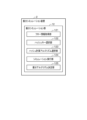
図6に示す振分シミュレーション装置2は、図1で示す、フロー情報取得部121、ハッシュキー選択部112、ハッシュ計算アルゴリズム選択部123、シミュレーション実行部124および振分アルゴリズム決定部125の機能を備える。これにより、振分シミュレーション装置2は、任意のフロー情報を入力することにより、各フローの振分先となるリンクの情報をシミュレーションし出力する。
本実施形態の変形例として、図1に示す振分シミュレーション部12の機能のみを備える装置(振分シミュレーション装置2)を説明する。
図6に示す振分シミュレーション装置2は、図1で示す、フロー情報取得部121、ハッシュキー選択部112、ハッシュ計算アルゴリズム選択部123、シミュレーション実行部124および振分アルゴリズム決定部125の機能を備える。これにより、振分シミュレーション装置2は、任意のフロー情報を入力することにより、各フローの振分先となるリンクの情報をシミュレーションし出力する。
通常、ECMPを採用している場合において、各フローがどのリンクを通っているかを判定することは難しい。これに対し、振分シミュレーション装置2を用いれば、例えば障害が発生した場合に、該当パスがどのリンクを通っているかを、フロー情報等に基づき迅速に確定することができる。これにより、障害発生後の対応をより早く行うことが可能となる。
<ハードウェア構成>
本実施形態に係るパケット転送制御装置1は、例えば図7に示すような構成のコンピュータ900によって実現される。
図7は、本実施形態に係るパケット転送制御装置1の機能を実現するコンピュータ900の一例を示すハードウェア構成図である。コンピュータ900は、CPU(Central Processing Unit)901、ROM(Read Only Memory)902、RAM903、HDD(Hard Disk Drive)904、入出力I/F(Interface)905、通信I/F906およびメディアI/F907を有する。
本実施形態に係るパケット転送制御装置1は、例えば図7に示すような構成のコンピュータ900によって実現される。
図7は、本実施形態に係るパケット転送制御装置1の機能を実現するコンピュータ900の一例を示すハードウェア構成図である。コンピュータ900は、CPU(Central Processing Unit)901、ROM(Read Only Memory)902、RAM903、HDD(Hard Disk Drive)904、入出力I/F(Interface)905、通信I/F906およびメディアI/F907を有する。
CPU901は、ROM902またはHDD904に記憶されたプログラムに基づき作動し、図1に示す各機能部による制御を行う。ROM902は、コンピュータ900の起動時にCPU901により実行されるブートプログラムや、コンピュータ900のハードウェアに係るプログラム等を記憶する。
CPU901は、入出力I/F905を介して、マウスやキーボード等の入力装置910、および、ディスプレイやプリンタ等の出力装置911を制御する。CPU901は、入出力I/F905を介して、入力装置910からデータを取得するともに、生成したデータを出力装置911へ出力する。なお、パケット転送制御装置1が、ASIC100等(図1参照)の振分処理機能を備える場合には、入出力I/F905を介して、情報の送受信を行う。
HDD904は、CPU901により実行されるプログラムおよび当該プログラムによって使用されるデータ等を記憶する。通信I/F906は、通信網(例えば、NW(Network)920)を介して他の装置からデータを受信してCPU901へ出力し、また、CPU901が生成したデータを、通信網を介して他の装置へ送信する。
メディアI/F907は、記録媒体912に格納されたプログラムまたはデータを読み取り、RAM903を介してCPU901へ出力する。CPU901は、目的の処理に係るプログラムを、メディアI/F907を介して記録媒体912からRAM903上にロードし、ロードしたプログラムを実行する。記録媒体912は、DVD(Digital Versatile Disc)、PD(Phase change rewritable Disk)等の光学記録媒体、MO(Magneto Optical disk)等の光磁気記録媒体、磁気記録媒体、半導体メモリ等である。
例えば、コンピュータ900が本実施形態に係るパケット転送制御装置1として機能する場合、コンピュータ900のCPU901は、RAM903上にロードされたプログラムを実行することにより、パケット転送制御装置1の機能を実現する。また、HDD904には、RAM903内のデータが記憶される。CPU901は、目的の処理に係るプログラムを記録媒体912から読み取って実行する。この他、CPU901は、他の装置から通信網(NW920)を介して目的の処理に係るプログラムを読み込んでもよい。
<効果>
以下、本発明に係るパケット転送制御装置1等の効果について説明する。
本発明に係るパケット転送制御装置は、パケットの転送処理における各リンクへの切り替えを制御するパケット転送制御装置1であって、パケットから収集されフローを特定する情報を含むパケット収集情報、および、当該フローが利用する帯域の情報、を含むフロー情報を取得するフロー情報取得部121と、パケット収集情報を用いて構成される情報であり、予め設定されるハッシュキー候補の中から1つを選択するハッシュキー選択部122と、予め設定されたハッシュ計算アルゴリズム候補の中から1つを選択するハッシュ計算アルゴリズム選択部123と、選択されたハッシュキー候補を用いて、選択されたハッシュ計算アルゴリズム候補により、フローの振り分け先となるリンクを算出するシミュレーションを、ハッシュキー候補およびハッシュ計算アルゴリズム候補のすべての組合せについて実行するシミュレーション実行部124と、シミュレーションの結果として得られた、ハッシュキー候補およびハッシュ計算アルゴリズム候補に応じた、フローの振り分け先となるリンクの情報の中から、フローの帯域の情報を用いて各リンクの利用帯域を算出し、所定のアルゴリズム決定ロジックに基づき、各リンクの利用帯域が最も分散している、ハッシュキー候補とハッシュ計算アルゴリズム候補の組を選択し、選択されたハッシュキー候補とハッシュ計算アルゴリズム候補の組の情報を出力する振分アルゴリズム決定部125と、選択されたハッシュキー候補とハッシュ計算アルゴリズム候補の組の情報を取得して、パケットを各リンクへ振り分ける振分処置機能に送信することにより、パケットの振り分け先となるリンクの設定を切り替えさせる振分アルゴリズム切替コントローラ13と、を備えることを特徴とする。
以下、本発明に係るパケット転送制御装置1等の効果について説明する。
本発明に係るパケット転送制御装置は、パケットの転送処理における各リンクへの切り替えを制御するパケット転送制御装置1であって、パケットから収集されフローを特定する情報を含むパケット収集情報、および、当該フローが利用する帯域の情報、を含むフロー情報を取得するフロー情報取得部121と、パケット収集情報を用いて構成される情報であり、予め設定されるハッシュキー候補の中から1つを選択するハッシュキー選択部122と、予め設定されたハッシュ計算アルゴリズム候補の中から1つを選択するハッシュ計算アルゴリズム選択部123と、選択されたハッシュキー候補を用いて、選択されたハッシュ計算アルゴリズム候補により、フローの振り分け先となるリンクを算出するシミュレーションを、ハッシュキー候補およびハッシュ計算アルゴリズム候補のすべての組合せについて実行するシミュレーション実行部124と、シミュレーションの結果として得られた、ハッシュキー候補およびハッシュ計算アルゴリズム候補に応じた、フローの振り分け先となるリンクの情報の中から、フローの帯域の情報を用いて各リンクの利用帯域を算出し、所定のアルゴリズム決定ロジックに基づき、各リンクの利用帯域が最も分散している、ハッシュキー候補とハッシュ計算アルゴリズム候補の組を選択し、選択されたハッシュキー候補とハッシュ計算アルゴリズム候補の組の情報を出力する振分アルゴリズム決定部125と、選択されたハッシュキー候補とハッシュ計算アルゴリズム候補の組の情報を取得して、パケットを各リンクへ振り分ける振分処置機能に送信することにより、パケットの振り分け先となるリンクの設定を切り替えさせる振分アルゴリズム切替コントローラ13と、を備えることを特徴とする。
このようにパケット転送制御装置1は、ハッシュキー候補とハッシュ計算アルゴリズム候補のすべての組み合わせについて、フローの振り分け先となるリンクを算出するシミュレーションを実行し、最も各リンクの利用帯域が分散されているハッシュキーとハッシュ計算アルゴリズムの組を選択することができる。これにより、パケット転送制御装置1は、各リンクの帯域の偏りの発生を抑制することができる。
また、パケット転送制御装置1は、このシミュレーションを、所定の時間間隔で繰り返すことにより、各フローの帯域変動に対応して最適なフローの負荷分散を実現することができる。
また、パケット転送制御装置1は、このシミュレーションを、所定の時間間隔で繰り返すことにより、各フローの帯域変動に対応して最適なフローの負荷分散を実現することができる。
また、パケット転送制御装置1において、所定のアルゴリズム決定ロジックは、ハッシュキー候補とハッシュ計算アルゴリズム候補の組それぞれで算出された各リンクの中で最も利用帯域が大きいリンクのうち、当該利用帯域が最小となるリンクが算出されたハッシュキー候補とハッシュ計算アルゴリズム候補の組を選択するロジックであることを特徴とする。
このような、アルゴリズム決定ロジックを用いることにより、パケット転送制御装置1は、各リンクの利用帯域を分散させ、帯域の偏りの発生を確実に抑制することができる。
また、パケット転送制御装置1において、所定のアルゴリズム決定ロジックは、ハッシュキー候補とハッシュ計算アルゴリズム候補の組それぞれの各リンクの利用帯域についての分散を算出し、最も分散の値が低い、ハッシュキー候補とハッシュ計算アルゴリズム候補の組を選択するロジックであることを特徴とする。
このような、アルゴリズム決定ロジックを用いることにより、パケット転送制御装置1は、各リンクの利用帯域を分散させ、帯域の偏りの発生を確実に抑制することができる。
本発明に係る振分シミュレーション装置2は、パケットから収集されフローを特定する情報を含むパケット収集情報、および、当該フローが利用する帯域の情報、を含むフロー情報を取得するフロー情報取得部121と、パケット収集情報を用いて構成される情報であり、予め設定されるハッシュキー候補の中から1つを選択するハッシュキー選択部122と、予め設定されたハッシュ計算アルゴリズム候補の中から1つを選択するハッシュ計算アルゴリズム選択部123と、選択されたハッシュキー候補を用いて、選択されたハッシュ計算アルゴリズム候補により、フローの振り分け先となるリンクを算出するシミュレーションを、ハッシュキー候補およびハッシュ計算アルゴリズム候補のすべての組合せについて実行するシミュレーション実行部124と、シミュレーションの結果として得られた、ハッシュキー候補およびハッシュ計算アルゴリズム候補に応じた、フローの振り分け先となるリンクの情報の中から、フローの帯域の情報を用いて各リンクの利用帯域を算出し、所定のアルゴリズム決定ロジックに基づき、各リンクの利用帯域が最も分散している、ハッシュキー候補とハッシュ計算アルゴリズム候補の組を選択し、選択されたハッシュキー候補とハッシュ計算アルゴリズム候補の組の情報を出力する振分アルゴリズム決定部125と、を備えることを特徴とする。
このように、振分シミュレーション装置2は、例えば、障害が発生した場合に、該当パスがどのリンクを通っているかを、フロー情報等に基づき迅速に確定することができる。
なお、本発明は、以上説明した実施形態に限定されるものではなく、多くの変形が本発明の技術的思想内で当分野において通常の知識を有する者により可能である。
1 パケット転送制御装置
2 振分シミュレーション装置
11 トラヒック情報取得部
12 振分シミュレーション部
13 振分アルゴリズム切替コントローラ
100 ASIC(振分処理機能)
101 ハッシュ切替機能部
121 フロー情報取得部
122 ハッシュキー選択部
123 ハッシュ計算アルゴリズム選択部
124 シミュレーション実行部
125 振分アルゴリズム決定部
200 フロー情報
300 シミュレーション結果情報
2 振分シミュレーション装置
11 トラヒック情報取得部
12 振分シミュレーション部
13 振分アルゴリズム切替コントローラ
100 ASIC(振分処理機能)
101 ハッシュ切替機能部
121 フロー情報取得部
122 ハッシュキー選択部
123 ハッシュ計算アルゴリズム選択部
124 シミュレーション実行部
125 振分アルゴリズム決定部
200 フロー情報
300 シミュレーション結果情報
Claims (6)
- パケットの転送処理における各リンクへの切り替えを制御するパケット転送制御装置であって、
前記パケットから収集されフローを特定する情報を含むパケット収集情報、および、当該フローが利用する帯域の情報、を含むフロー情報を取得するフロー情報取得部と、
前記パケット収集情報を用いて構成される情報であり、予め設定されるハッシュキー候補の中から1つを選択するハッシュキー選択部と、
予め設定されたハッシュ計算アルゴリズム候補の中から1つを選択するハッシュ計算アルゴリズム選択部と、
選択された前記ハッシュキー候補を用いて、選択された前記ハッシュ計算アルゴリズム候補により、前記フローの振り分け先となるリンクを算出するシミュレーションを、前記ハッシュキー候補および前記ハッシュ計算アルゴリズム候補のすべての組合せについて実行するシミュレーション実行部と、
前記シミュレーションの結果として得られた、前記ハッシュキー候補および前記ハッシュ計算アルゴリズム候補に応じた、前記フローの振り分け先となるリンクの情報の中から、前記フローの帯域の情報を用いて各リンクの利用帯域を算出し、所定のアルゴリズム決定ロジックに基づき、各リンクの利用帯域が最も分散している、前記ハッシュキー候補と前記ハッシュ計算アルゴリズム候補の組を選択し、選択された前記ハッシュキー候補と前記ハッシュ計算アルゴリズム候補の組の情報を出力する振分アルゴリズム決定部と、
選択された前記ハッシュキー候補と前記ハッシュ計算アルゴリズム候補の組の情報を取得して、前記パケットを各リンクへ振り分ける振分処置機能に送信することにより、前記パケットの振り分け先となるリンクの設定を切り替えさせる振分アルゴリズム切替コントローラと、
を備えることを特徴とするパケット転送制御装置。 - 前記所定のアルゴリズム決定ロジックは、前記ハッシュキー候補と前記ハッシュ計算アルゴリズム候補の組それぞれで算出された各リンクの中で最も利用帯域が大きいリンクのうち、当該利用帯域が最小となるリンクが算出された前記ハッシュキー候補と前記ハッシュ計算アルゴリズム候補の組を選択するロジックであること
を特徴とする請求項1に記載のパケット転送制御装置。 - 前記所定のアルゴリズム決定ロジックは、前記ハッシュキー候補と前記ハッシュ計算アルゴリズム候補の組それぞれの各リンクの利用帯域についての分散を算出し、最も分散の値が低い、前記ハッシュキー候補と前記ハッシュ計算アルゴリズム候補の組を選択するロジックであること
を特徴とする請求項1に記載のパケット転送制御装置。 - パケットの転送処理における各リンクへの切り替えを制御するパケット転送制御装置のパケット転送制御方法であって、
前記パケット転送制御装置は、
前記パケットから収集されフローを特定する情報を含むパケット収集情報、および、当該フローが利用する帯域の情報、を含むフロー情報を取得するステップと、
前記パケット収集情報を用いて構成される情報であり、予め設定されるハッシュキー候補の中から1つを選択するステップと、
予め設定されたハッシュ計算アルゴリズム候補の中から1つを選択するステップと、
選択された前記ハッシュキー候補を用いて、選択された前記ハッシュ計算アルゴリズム候補により、前記フローの振り分け先となるリンクを算出するシミュレーションを、前記ハッシュキー候補および前記ハッシュ計算アルゴリズム候補のすべての組合せについて実行するステップと、
前記シミュレーションの結果として得られた、前記ハッシュキー候補および前記ハッシュ計算アルゴリズム候補に応じた、前記フローの振り分け先となるリンクの情報の中から、前記フローの帯域の情報を用いて各リンクの利用帯域を算出し、所定のアルゴリズム決定ロジックに基づき、各リンクの利用帯域が最も分散している、前記ハッシュキー候補と前記ハッシュ計算アルゴリズム候補の組を選択し、選択された前記ハッシュキー候補と前記ハッシュ計算アルゴリズム候補の組の情報を出力するステップと、
選択された前記ハッシュキー候補と前記ハッシュ計算アルゴリズム候補の組の情報を取得して、前記パケットを各リンクへ振り分ける振分処置機能に送信することにより、前記パケットの振り分け先となるリンクの設定を切り替えさせるステップと、
を実行することを特徴とするパケット転送制御方法。 - パケットから収集されフローを特定する情報を含むパケット収集情報、および、当該フローが利用する帯域の情報、を含むフロー情報を取得するフロー情報取得部と、
前記パケット収集情報を用いて構成される情報であり、予め設定されるハッシュキー候補の中から1つを選択するハッシュキー選択部と、
予め設定されたハッシュ計算アルゴリズム候補の中から1つを選択するハッシュ計算アルゴリズム選択部と、
選択された前記ハッシュキー候補を用いて、選択された前記ハッシュ計算アルゴリズム候補により、前記フローの振り分け先となるリンクを算出するシミュレーションを、前記ハッシュキー候補および前記ハッシュ計算アルゴリズム候補のすべての組合せについて実行するシミュレーション実行部と、
前記シミュレーションの結果として得られた、前記ハッシュキー候補および前記ハッシュ計算アルゴリズム候補に応じた、前記フローの振り分け先となるリンクの情報の中から、前記フローの帯域の情報を用いて各リンクの利用帯域を算出し、所定のアルゴリズム決定ロジックに基づき、各リンクの利用帯域が最も分散している、前記ハッシュキー候補と前記ハッシュ計算アルゴリズム候補の組を選択し、選択された前記ハッシュキー候補と前記ハッシュ計算アルゴリズム候補の組の情報を出力する振分アルゴリズム決定部と、
を備えることを特徴とする振分シミュレーション装置。 - コンピュータを、請求項1乃至請求項3の何れか1項に記載のパケット転送制御装置として機能させるためのプログラム。
Priority Applications (2)
| Application Number | Priority Date | Filing Date | Title |
|---|---|---|---|
| PCT/JP2022/031353 WO2024038579A1 (ja) | 2022-08-19 | 2022-08-19 | パケット転送制御装置、パケット転送制御方法、振分シミュレーション装置、および、プログラム |
| JP2024541373A JP7750423B2 (ja) | 2022-08-19 | 2022-08-19 | パケット転送制御装置、パケット転送制御方法、振分シミュレーション装置、および、プログラム |
Applications Claiming Priority (1)
| Application Number | Priority Date | Filing Date | Title |
|---|---|---|---|
| PCT/JP2022/031353 WO2024038579A1 (ja) | 2022-08-19 | 2022-08-19 | パケット転送制御装置、パケット転送制御方法、振分シミュレーション装置、および、プログラム |
Publications (1)
| Publication Number | Publication Date |
|---|---|
| WO2024038579A1 true WO2024038579A1 (ja) | 2024-02-22 |
Family
ID=89941620
Family Applications (1)
| Application Number | Title | Priority Date | Filing Date |
|---|---|---|---|
| PCT/JP2022/031353 Ceased WO2024038579A1 (ja) | 2022-08-19 | 2022-08-19 | パケット転送制御装置、パケット転送制御方法、振分シミュレーション装置、および、プログラム |
Country Status (2)
| Country | Link |
|---|---|
| JP (1) | JP7750423B2 (ja) |
| WO (1) | WO2024038579A1 (ja) |
Citations (2)
| Publication number | Priority date | Publication date | Assignee | Title |
|---|---|---|---|---|
| JP2015050527A (ja) * | 2013-08-30 | 2015-03-16 | 日本電信電話株式会社 | パケット転送装置、パケット転送システム、およびパケット転送方法 |
| JP2018534830A (ja) * | 2015-09-24 | 2018-11-22 | アリババ・グループ・ホールディング・リミテッドAlibaba Group Holding Limited | サービス伝送速度を制御するための方法、装置及びシステム |
-
2022
- 2022-08-19 WO PCT/JP2022/031353 patent/WO2024038579A1/ja not_active Ceased
- 2022-08-19 JP JP2024541373A patent/JP7750423B2/ja active Active
Patent Citations (2)
| Publication number | Priority date | Publication date | Assignee | Title |
|---|---|---|---|---|
| JP2015050527A (ja) * | 2013-08-30 | 2015-03-16 | 日本電信電話株式会社 | パケット転送装置、パケット転送システム、およびパケット転送方法 |
| JP2018534830A (ja) * | 2015-09-24 | 2018-11-22 | アリババ・グループ・ホールディング・リミテッドAlibaba Group Holding Limited | サービス伝送速度を制御するための方法、装置及びシステム |
Also Published As
| Publication number | Publication date |
|---|---|
| JP7750423B2 (ja) | 2025-10-07 |
| JPWO2024038579A1 (ja) | 2024-02-22 |
Similar Documents
| Publication | Publication Date | Title |
|---|---|---|
| CN107852368B (zh) | 用于网络服务的高度可用的服务链 | |
| EP2656546B1 (en) | Communications network management | |
| CN1918861B (zh) | 通信网络中的流量流确定 | |
| EP3251310B1 (en) | Method,apparatus and machine readable medium for traffic engineering in communications network having quality of service flows and best effort flows | |
| US20170019303A1 (en) | Service Chains for Network Services | |
| US20240314070A1 (en) | Traffic monitoring and orchestration | |
| WO2011049135A1 (ja) | ネットワークシステムとその制御方法、及びコントローラ | |
| US9584422B2 (en) | Methods and apparatuses for automating return traffic redirection to a service appliance by injecting traffic interception/redirection rules into network nodes | |
| Chahlaoui et al. | Performance analysis of load balancing mechanisms in SDN networks | |
| US11750518B2 (en) | Elastic modification of application instances in a network visibility infrastructure | |
| US20240129245A1 (en) | System and method for reactive path selection | |
| Dinh et al. | MSDN-TE: Multipath based traffic engineering for SDN | |
| US20220124038A1 (en) | Device and method for improved load balancing with limited forwarding rules in software defined networks | |
| Nepolo et al. | A predictive ECMP routing protocol for fat-tree enabled data centre networks | |
| JP7750423B2 (ja) | パケット転送制御装置、パケット転送制御方法、振分シミュレーション装置、および、プログラム | |
| KR20160139591A (ko) | 라우팅 방법 및 그 장치 | |
| WO2021240586A1 (ja) | コネクション数計測装置、コネクション状態検出装置、コネクション状態検出方法、およびコネクション数計測プログラム | |
| Murphy | Capacity Management: Using The Dual Solution of the Multi-Commodity Flow Problem to Set OSPF Weights-a Fast Heuristic | |
| JP6071809B2 (ja) | トラフィック分析システム、トラフィック分析方法およびコンピュータプログラム | |
| Florea et al. | Routing enhancements based on evolutionary algorithm |
Legal Events
| Date | Code | Title | Description |
|---|---|---|---|
| 121 | Ep: the epo has been informed by wipo that ep was designated in this application |
Ref document number: 22955752 Country of ref document: EP Kind code of ref document: A1 |
|
| WWE | Wipo information: entry into national phase |
Ref document number: 2024541373 Country of ref document: JP |
|
| NENP | Non-entry into the national phase |
Ref country code: DE |
|
| 122 | Ep: pct application non-entry in european phase |
Ref document number: 22955752 Country of ref document: EP Kind code of ref document: A1 |