WO2024034570A1 - 通信制御方法 - Google Patents
通信制御方法 Download PDFInfo
- Publication number
- WO2024034570A1 WO2024034570A1 PCT/JP2023/028764 JP2023028764W WO2024034570A1 WO 2024034570 A1 WO2024034570 A1 WO 2024034570A1 JP 2023028764 W JP2023028764 W JP 2023028764W WO 2024034570 A1 WO2024034570 A1 WO 2024034570A1
- Authority
- WO
- WIPO (PCT)
- Prior art keywords
- node
- iab
- mobile
- handover
- iab node
- Prior art date
- Legal status (The legal status is an assumption and is not a legal conclusion. Google has not performed a legal analysis and makes no representation as to the accuracy of the status listed.)
- Ceased
Links
Images




Classifications
-
- H—ELECTRICITY
- H04—ELECTRIC COMMUNICATION TECHNIQUE
- H04W—WIRELESS COMMUNICATION NETWORKS
- H04W36/00—Hand-off or reselection arrangements
- H04W36/34—Reselection control
- H04W36/36—Reselection control by user or terminal equipment
- H04W36/362—Conditional handover
-
- H—ELECTRICITY
- H04—ELECTRIC COMMUNICATION TECHNIQUE
- H04W—WIRELESS COMMUNICATION NETWORKS
- H04W36/00—Hand-off or reselection arrangements
- H04W36/0005—Control or signalling for completing the hand-off
- H04W36/0055—Transmission or use of information for re-establishing the radio link
- H04W36/0072—Transmission or use of information for re-establishing the radio link of resource information of target access point
- H04W36/00725—Random access channel [RACH]-less handover
-
- H—ELECTRICITY
- H04—ELECTRIC COMMUNICATION TECHNIQUE
- H04W—WIRELESS COMMUNICATION NETWORKS
- H04W36/00—Hand-off or reselection arrangements
- H04W36/0005—Control or signalling for completing the hand-off
- H04W36/0055—Transmission or use of information for re-establishing the radio link
- H04W36/0077—Transmission or use of information for re-establishing the radio link of access information of target access point
-
- H—ELECTRICITY
- H04—ELECTRIC COMMUNICATION TECHNIQUE
- H04W—WIRELESS COMMUNICATION NETWORKS
- H04W36/00—Hand-off or reselection arrangements
- H04W36/08—Reselecting an access point
-
- H—ELECTRICITY
- H04—ELECTRIC COMMUNICATION TECHNIQUE
- H04W—WIRELESS COMMUNICATION NETWORKS
- H04W92/00—Interfaces specially adapted for wireless communication networks
- H04W92/16—Interfaces between hierarchically similar devices
- H04W92/20—Interfaces between hierarchically similar devices between access points
Definitions
- the present disclosure relates to a communication control method used in a cellular communication system.
- Non-Patent Document 1 Integrated Access and Backhaul node
- the communication control method is a communication control method used in a cellular communication system.
- the communication control method includes the step of the base station transmitting conditional reconfiguration including permission information indicating whether or not connection by RACHless handover is permitted for each target cell to the user equipment.
- the communication control method is a communication control method used in a cellular communication system.
- the communication control method includes the step of the donor node transmitting conditional reconfiguration including an execution condition to be executed upon receiving an execution instruction to a user device under the mobile relay node. Further, the communication control method includes the step of the donor node transmitting a transmission instruction to the mobile relay node to instruct transmission of the execution instruction. Further, the communication control method includes the step of the mobile relay node transmitting an execution instruction to the user device in response to receiving the transmission instruction.
- the communication control method is a communication control method used in a cellular communication system.
- the communication control method includes the step of the donor node transmitting to the mobile relay node a first message including common settings common to a plurality of user devices under the mobile relay node.
- the communication control method also includes the step of the donor node transmitting a second message including individual settings of each user device under the mobile relay node to the mobile relay node.
- the communication control method includes the step of the mobile relay node transmitting an RRC reconfiguration message including common settings and individual settings to each user equipment.
- FIG. 1 is a diagram illustrating a configuration example of a cellular communication system according to an embodiment.
- FIG. 2 is a diagram showing the relationship between IAB nodes, parent nodes, and child nodes.
- FIG. 3 is a diagram illustrating a configuration example of a gNB (base station) according to an embodiment.
- FIG. 4 is a diagram illustrating a configuration example of an IAB node (relay node) according to an embodiment.
- FIG. 5 is a diagram illustrating a configuration example of a UE (user equipment) according to an embodiment.
- FIG. 6 is a diagram illustrating an example of a protocol stack regarding RRC connection and NAS connection of IAB-MT.
- FIG. 7 is a diagram illustrating an example of a protocol stack regarding the F1-U protocol.
- FIG. 8 is a diagram showing an example of a protocol stack regarding the F1-C protocol.
- FIG. 9 is a diagram illustrating an operation example according to the first embodiment.
- FIG. 10 is a diagram illustrating another example of operation according to the first embodiment.
- FIG. 11 is a diagram illustrating an operation example of solution 2 according to the second embodiment.
- FIG. 12 is a diagram illustrating an operation example according to the second embodiment.
- FIG. 13 is a diagram illustrating another example of operation according to the second embodiment.
- FIGS. 14A and 14B are diagrams illustrating an example of group handover operation according to the third embodiment.
- FIG. 15 is a diagram illustrating an operation example according to the third embodiment.
- FIG. 16 is a diagram illustrating another example of operation according to the third embodiment.
- FIG. 17 is a diagram showing an example of traditional handover (top) and an example of group reconfiguration (bottom).
- FIG. 18 is a diagram illustrating Solution 1 for reducing service interruptions.
- FIG. 19 is a
- the cellular communication system 1 is a 3GPP 5G system.
- the radio access method in the cellular communication system 1 is NR (New Radio), which is a 5G radio access method.
- NR New Radio
- LTE Long Term Evolution
- 6G future cellular communication systems such as 6G may also be applied to the cellular communication system 1.
- FIG. 1 is a diagram showing a configuration example of a cellular communication system 1 according to an embodiment.
- the cellular communication system 1 includes a 5G core network (5GC) 10, a user equipment (UE) 100, and a base station device (hereinafter sometimes referred to as "base station") 200. -1, 200-2, and IAB nodes 300-1, 300-2.
- Base station 200 may be called a gNB.
- the base station 200 may be an LTE base station (i.e., an eNB).
- the base stations 200-1 and 200-2 may be referred to as gNB 200 (or base station 200), and the IAB nodes 300-1 and 300-2 may be referred to as IAB node 300, respectively.
- the 5GC 10 has an AMF (Access and Mobility Management Function) 11 and a UPF (User Plane Function) 12.
- the AMF 11 is a device that performs various mobility controls for the UE 100.
- the AMF 11 manages information about the area where the UE 100 is located by communicating with the UE 100 using NAS (Non-Access Stratum) signaling.
- the UPF 12 is a device that controls the transfer of user data.
- Each gNB 200 is a fixed wireless communication node and manages one or more cells.
- a cell is a term used to indicate the smallest unit of a wireless communication area.
- a cell is sometimes used as a term indicating a function or resource for performing wireless communication with the UE 100.
- One cell belongs to one carrier frequency. In the following, cells and base stations may be used without distinction.
- Each gNB 200 is interconnected with the 5GC 10 via an interface called an NG interface.
- an NG interface In FIG. 1, two gNB200-1 and gNB200-2 connected to 5GC10 are illustrated.
- Each gNB 200 may be divided into a central unit (CU) and a distributed unit (DU).
- CU and DU are interconnected via an interface called F1 interface.
- the F1 protocol is a communication protocol between the CU and DU, and includes the F1-C protocol, which is a control plane protocol, and the F1-U protocol, which is a user plane protocol.
- the cellular communication system 1 supports IAB that uses NR for backhaul and enables wireless relay of NR access.
- the donor gNB 200-1 (or donor node, hereinafter sometimes referred to as "donor node") is a terminal node of the NR backhaul on the network side, and is a donor base station equipped with additional functions to support IAB. .
- the backhaul can be multi-hop through multiple hops (ie, multiple IAB nodes 300).
- IAB node 300-1 is wirelessly connected to donor node 200-1
- IAB node 300-2 is wirelessly connected to IAB node 300-1
- the F1 protocol is transmitted over two backhaul hops. An example is shown.
- the UE 100 is a mobile wireless communication device that performs wireless communication with a cell.
- the UE 100 may be any device that performs wireless communication with the gNB 200 or the IAB node 300.
- the UE 100 is a mobile phone terminal and/or a tablet terminal, a notebook PC, a sensor or a device provided on the sensor, a vehicle or a device provided on the vehicle, an aircraft, or a device provided on the aircraft.
- UE 100 wirelessly connects to IAB node 300 or gNB 200 via an access link.
- FIG. 1 shows an example in which the UE 100 is wirelessly connected to the IAB node 300-2.
- UE 100 indirectly communicates with donor node 200-1 via IAB node 300-2 and IAB node 300-1.
- FIG. 2 is a diagram showing an example of the relationship between the IAB node 300, parent nodes, and child nodes.
- each IAB node 300 has an IAB-DU that corresponds to a base station function unit and an IAB-MT (Mobile Termination) that corresponds to a user equipment function unit.
- IAB-DU that corresponds to a base station function unit
- IAB-MT Mobile Termination
- the adjacent node (ie, the upper node) on the NR Uu radio interface of the IAB-MT is called the parent node.
- the parent node is the DU of the parent IAB node or donor node 200.
- the wireless link between the IAB-MT and the parent node is called the backhaul link (BH link).
- FIG. 2 shows an example in which the parent nodes of the IAB node 300 are IAB nodes 300-P1 and 300-P2. Note that the direction toward the parent node is called upstream. Seen from the UE 100, a higher-order node of the UE 100 may correspond to a parent node.
- Adjacent nodes (ie, subordinate nodes) on the NR access interface of the IAB-DU are called child nodes.
- the IAB-DU manages cells in the same way as the gNB 200.
- the IAB-DU terminates the NR Uu radio interface to the UE 100 and lower IAB nodes.
- IAB-DU supports the F1 protocol to the CU of donor node 200-1.
- FIG. 2 shows an example in which the child nodes of the IAB node 300 are the IAB nodes 300-C1 to 300-C3, the child nodes of the IAB node 300 may include the UE 100. Note that the direction toward the child node is called downstream.
- all IAB nodes 300 connected to the donor node 200 via one or more hops have a directed acyclic graph (DAG) topology (hereinafter referred to as (sometimes referred to as a "topology").
- DAG directed acyclic graph
- adjacent nodes on the IAB-DU interface are child nodes
- adjacent nodes on the IAB-MT interface are parent nodes.
- the donor node 200 centrally manages, for example, the resources, topology, and routes of the IAB topology.
- Donor node 200 is a gNB that provides network access to UE 100 via a network of backhaul links and access links.
- FIG. 3 is a diagram showing a configuration example of the gNB 200.
- the gNB 200 includes a wireless communication section 210, a network communication section 220, and a control section 230.
- the wireless communication unit 210 performs wireless communication with the UE 100 and the IAB node 300.
- the wireless communication section 210 includes a receiving section 211 and a transmitting section 212.
- the receiving unit 211 performs various types of reception under the control of the control unit 230.
- Receiving section 211 includes an antenna, converts (down converts) a radio signal received by the antenna into a baseband signal (received signal), and outputs the baseband signal (received signal) to control section 230 .
- the transmitter 212 performs various types of transmission under the control of the controller 230.
- the transmitter 212 includes an antenna, converts (up-converts) the baseband signal (transmission signal) output by the controller 230 into a wireless signal, and transmits it from the antenna.
- the network communication unit 220 performs wired communication (or wireless communication) with the 5GC 10 and wired communication (or wireless communication) with other adjacent gNBs 200.
- the network communication section 220 includes a receiving section 221 and a transmitting section 222.
- the receiving unit 221 performs various types of reception under the control of the control unit 230.
- the receiving section 221 receives a signal from the outside and outputs the received signal to the control section 230.
- the transmitter 222 performs various types of transmission under the control of the controller 230.
- the transmitter 222 transmits the transmit signal output by the controller 230 to the outside.
- the control unit 230 performs various controls in the gNB 200.
- Control unit 230 includes at least one memory and at least one processor electrically connected to the memory.
- the memory stores programs executed by the processor and information used in processing by the processor.
- the processor may include a baseband processor and a CPU.
- the baseband processor performs modulation/demodulation, encoding/decoding, etc. of the baseband signal.
- the CPU executes programs stored in memory to perform various processes.
- the processor processes each layer, which will be described later. Note that the control unit 230 may perform each process or each operation in the gNB 200 in each embodiment described below.
- FIG. 4 is a diagram showing a configuration example of the IAB node 300.
- the IAB node 300 includes a wireless communication section 310 and a control section 320.
- the IAB node 300 may have a plurality of wireless communication units 310.
- the wireless communication unit 310 performs wireless communication with the gNB 200 (BH link) and wireless communication with the UE 100 (access link).
- the wireless communication unit 310 for BH link communication and the wireless communication unit 310 for access link communication may be provided separately.
- the wireless communication section 310 includes a receiving section 311 and a transmitting section 312.
- the receiving unit 311 performs various types of reception under the control of the control unit 320.
- Receiving section 311 includes an antenna, converts (down converts) a radio signal received by the antenna into a baseband signal (received signal), and outputs the baseband signal (received signal) to control section 320 .
- the transmitter 312 performs various types of transmission under the control of the controller 320.
- the transmitter 312 includes an antenna, converts (up-converts) the baseband signal (transmission signal) output by the controller 320 into a wireless signal, and transmits it from the antenna.
- the control unit 320 performs various controls in the IAB node 300.
- Control unit 320 includes at least one memory and at least one processor electrically connected to the memory.
- the memory stores programs executed by the processor and information used in processing by the processor.
- the processor may include a baseband processor and a CPU.
- the baseband processor performs modulation/demodulation, encoding/decoding, etc. of the baseband signal.
- the CPU executes programs stored in memory to perform various processes.
- the processor processes each layer, which will be described later. Note that the control unit 320 may perform each process or each operation in the IAB node 300 in each embodiment described below.
- FIG. 5 is a diagram showing a configuration example of the UE 100.
- UE 100 includes a wireless communication section 110 and a control section 120.
- the wireless communication unit 110 performs wireless communication on the access link, that is, wireless communication with the gNB 200 and wireless communication with the IAB node 300. Furthermore, the wireless communication unit 110 may perform sidelink wireless communication, that is, wireless communication with other UEs 100.
- the wireless communication section 110 includes a receiving section 111 and a transmitting section 112.
- the receiving unit 111 performs various types of reception under the control of the control unit 120.
- Receiving section 111 includes an antenna, converts (down converts) a radio signal received by the antenna into a baseband signal (received signal), and outputs the baseband signal (received signal) to control section 120 .
- the transmitter 112 performs various types of transmission under the control of the controller 120.
- the transmitter 112 includes an antenna, converts (up-converts) the baseband signal (transmission signal) output by the controller 120 into a wireless signal, and transmits it from the antenna.
- the control unit 120 performs various controls in the UE 100.
- Control unit 120 includes at least one memory and at least one processor electrically connected to the memory.
- the memory stores programs executed by the processor and information used in processing by the processor.
- the processor may include a baseband processor and a CPU.
- the baseband processor performs modulation/demodulation, encoding/decoding, etc. of the baseband signal.
- the CPU executes programs stored in memory to perform various processes.
- the processor processes each layer, which will be described later. Note that the control unit 120 may perform each process in the UE 100 in each embodiment described below.
- FIG. 6 is a diagram illustrating an example of a protocol stack regarding RRC connection and NAS connection of IAB-MT.
- the IAB-MT of the IAB node 300-2 includes a physical (PHY) layer, a MAC (Medium Access Control) layer, an RLC (Radio Link Control) layer, and a PDCP (Packet Data Convergence Protocol) layer. layer, an RRC (Radio Resource Control) layer, and a NAS (Non-Access Stratum) layer.
- PHY physical
- MAC Medium Access Control
- RLC Radio Link Control
- PDCP Packet Data Convergence Protocol
- RRC Radio Resource Control
- NAS Non-Access Stratum
- the PHY layer performs encoding/decoding, modulation/demodulation, antenna mapping/demapping, and resource mapping/demapping. Data and control information are transmitted between the PHY layer of the IAB-MT of the IAB node 300-2 and the PHY layer of the IAB-DU of the IAB node 300-1 via a physical channel.
- the MAC layer performs data priority control, retransmission processing using Hybrid ARQ (HARQ: Hybrid Automatic Repeat reQuest), random access procedure, etc.
- Data and control information are transmitted between the IAB-MT MAC layer of IAB node 300-2 and the IAB-DU MAC layer of IAB node 300-1 via a transport channel.
- the IAB-DU MAC layer includes a scheduler. The scheduler determines uplink and downlink transport formats (transport block size, modulation and coding scheme (MCS)) and allocated resource blocks.
- MCS modulation and coding scheme
- the RLC layer uses the functions of the MAC layer and PHY layer to transmit data to the RLC layer on the receiving side. Data and control information are transmitted between the RLC layer of the IAB-MT of the IAB node 300-2 and the RLC layer of the IAB-DU of the IAB node 300-1 via logical channels.
- the PDCP layer performs header compression/expansion, and encryption/decryption. Data and control information are transmitted between the PDCP layer of the IAB-MT of the IAB node 300-2 and the PDCP layer of the donor node 200 via radio bearers.
- the RRC layer controls logical channels, transport channels and physical channels according to the establishment, re-establishment and release of radio bearers.
- RRC signaling for various settings is transmitted between the IAB-MT RRC layer of IAB node 300-2 and the RRC layer of donor node 200. If there is an RRC connection with the donor node 200, the IAB-MT is in the RRC connected state. If there is no RRC connection with donor node 200, IAB-MT is in RRC idle state.
- the NAS layer located above the RRC layer performs session management, mobility management, etc.
- NAS signaling is transmitted between the NAS layer of the IAB-MT of the IAB node 300-2 and the AMF 11.
- FIG. 7 is a diagram showing a protocol stack regarding the F1-U protocol.
- FIG. 8 is a diagram showing a protocol stack regarding the F1-C protocol.
- the donor node 200 is divided into a CU and a DU.
- each of the IAB-MT of the IAB node 300-2, the IAB-DU of the IAB node 300-1, the IAB-MT of the IAB node 300-1, and the DU of the donor node 200 is configured in the RLC layer. It has a BAP (Backhaul Adaptation Protocol) layer as an upper layer.
- the BAP layer is a layer that performs routing processing and bearer mapping/demapping processing. In backhaul, the IP layer is transmitted through the BAP layer, allowing multi-hop routing.
- BAP layer PDUs Protocol Data Units
- BH NR RLC channel backhaul RLC channel
- QoS Quality of Service
- the protocol stack of the F1-C protocol has an F1AP layer and an SCTP layer instead of the GTP-U layer and UDP layer shown in FIG.
- IAB-DU and IAB-MT of IAB may be simply described as "IAB" processing or operation.
- IAB processing or operation
- the IAB-DU of the IAB node 300-1 sends a BAP layer message to the IAB-MT of the IAB node 300-2
- the IAB node 300-1 sends the message to the IAB node 300-2.
- the processing or operation of the DU or CU of the donor node 200 may also be simply described as the processing or operation of the "donor node.”
- upstream direction and the uplink (UL) direction may be used without distinguishing between them.
- downstream direction and the downlink (DL) direction may be used interchangeably.
- a mobile IAB node is, for example, an IAB node that is moving.
- a mobile IAB node may be a mobile IAB node.
- a mobile IAB node may be an IAB node that has the ability to move.
- a mobile IAB node may be an IAB node that is currently stationary but is certain to move (or is expected to move in the future) in the future.
- the mobile IAB node allows the UE 100 under the mobile IAB node to receive services from the mobile IAB node while moving as the mobile IAB node moves. For example, a case is assumed in which a user (or UE 100) riding in a vehicle receives services via a mobile IAB node installed in the vehicle.
- IAB nodes that never move.
- An IAB node may be referred to as an intermediate IAB node.
- An intermediate IAB node is, for example, an IAB node that does not move.
- the intermediate IAB node may be a stationary IAB node.
- An intermediate IAB node may be a stationary IAB node.
- the intermediate IAB node may be a stationary (or non-moving) IAB node that remains installed at the installation site.
- the intermediate IAB node may be a stationary IAB node that does not move.
- Intermediate IAB nodes may be fixed IAB nodes.
- a mobile IAB node can also connect to intermediate IAB nodes.
- a mobile IAB node may also be connected to a donor node.
- a mobile IAB node can also change its connection destination by moving (migration or handover).
- the connection source may be an intermediate IAB node.
- the connection source may be a donor node.
- the connection destination may be an intermediate IAB node.
- the connection destination may be a donor node.
- RACH-less handover 3GPP defines RACH-less handover (RACH-less HO) (for example, 3GPP TS 36.300 V14.13.0 (2020-12)).
- RACH-less handover is a handover in which a random access procedure is skipped. In RACH-less handover, for example, the following processing is performed.
- the UE 100 configured for RACH-less handover receives an RRC Connection Reconfiguration message from the source cell. Then, the UE 100 synchronizes with the target cell included in the RRC connection reconfiguration message without executing a random access (RACH) procedure. Thereafter, the UE 100 uses the uplink resources included in the RRC connection reconfiguration message to transmit an RRC Connection Reconfiguration Complete message to the target cell, and ends the handover procedure.
- RACH random access
- the UE 100 can improve the delay in handover execution time compared to the case where the random access procedure is executed.
- condition handover In a typical handover, the UE 100 reports measured values of the radio conditions of the serving cell and/or neighboring cells to the gNB 200, and based on this report, the gNB 200 determines handover to the neighboring cell and sends a handover instruction to the UE 100. . For this reason, when the radio condition of the serving cell suddenly deteriorates, communication may be interrupted before the handover is executed in a typical handover.
- conditional handover when a preset trigger condition is satisfied, the UE 100 can autonomously execute handover to a candidate cell corresponding to the trigger condition. Therefore, problems such as communication interruption during general handover can be solved.
- Conditional handover configuration is performed by conditional reconfiguration.
- Conditional reconfiguration is one of the information elements (IE) included in the RRC Reconfiguration message.
- Conditional reconfiguration is performed, for example, by transmitting an RRC reconfiguration message from the CU of the donor node 200 to the IAB-MT of the IAB node 300 and the UE 100.
- Conditional reconfiguration includes candidate cells and execution conditions used in conditional handover. Execution conditions include one or more trigger conditions. The IAB-MT of the IAB node 300 and the UE 100 start performing handover to the candidate cell when the trigger condition is met.
- the mobile IAB node may cause the UEs 100 under the mobile IAB node to perform handover all at once due to its own handover.
- the cell ID of the cell to which the mobile IAB node is connected changes. As the cell ID to which the mobile IAB node connects changes due to handover, it may be easier to manage the UE 100 under the mobile IAB node by changing the cell ID to which the UE 100 under the mobile IAB node connects. Conceivable. Therefore, the above-mentioned case is assumed.
- the CU that performs RRC settings.
- the DU that manages the cell.
- the DU of the gNB 200 may know which cells have the same timing advance (TA) value among the cells managed by the DU.
- the IAB-DU of the mobile IAB node may know the distance to the UE 100 under its control, as described above.
- the CU (the CU of the gNB 200 or the CU of the donor node 200) does not know the situation of the cell, it may not be possible to appropriately set RACH-less handover for the UE 100. In this case, UE 100 cannot properly connect to the network.
- the first embodiment aims to enable the UE 100 to appropriately connect to the network.
- a base station for example, gNB 200 or donor node 200 connects a user equipment (for example, UE 100 under gNB 200 or mobile IAB node 300M under RACHless handover) for each target cell.
- a conditional reconfiguration message containing permission information indicating whether or not is permitted is sent.
- the UE 100 can determine which target cell to connect to in order to perform a RACH-less handover at the time of handover. Therefore, in the UE 100, if the target cell is permitted to connect by RACH-less handover, it is possible to perform RACH-less handover to the target cell. Therefore, the UE 100 can appropriately connect to the network.
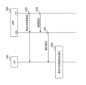
- FIG. 9 is a diagram illustrating an operation example according to the first embodiment.
- the UE 100 is a UE under the mobile IAB node 300M, and represents an example in which the UE 100 is handed over in conjunction with the handover of the mobile IAB node 300M.
- the source cell is the cell to which the mobile IAB node 300M was connected before handover (for example, the cell managed by the DU of the donor node 200).
- the target cell may be a cell to which the mobile IAB node 300M is connected by handover (for example, a cell managed by the DU of the donor node 200.
- the target cell may be a cell managed by the DU of the donor node 200. It may also be a cell managed by IAB-DU).
- step S10 the UE 100 sends a RACH-less handover to the CU (IAB-donor-CU) of the donor node 200, indicating that the UE 100 has the ability to perform a RACH-less handover. Capability information may also be sent.
- the RACH-less handover capability information may be information indicating that the UE 100 supports RACH-less handover.
- the UE 100 may transmit an RRC message including RACHless handover capability information to the IAB-DU of the mobile IAB node 300M.
- the IAB-DU of the mobile IAB node 300M may then transmit an F1 message including the RRC message to the CU of the donor node 200.
- step S11 the IAB-DU of the mobile IAB node 300M transmits to the CU of the donor node 200 combination information representing a combination of cells in which RACH-less handover is possible among the cells it manages.
- the IAB-DU of the mobile IAB node 300M may send an F1 message containing the combination information to the CU of the donor node 200.
- the CU of the donor node 200 may request the mobile IAB node 300M for the combination information.
- the CU of the donor node 200 may transmit an F1 message including a request for the combination information to the IAB-DU of the mobile IAB node 300M.
- the combination of cells may be cells that are located in the same geographical location. For example, if the source cell and target cell are physically the same. Alternatively, for example, there is a case where the UE 100 moves due to handover of the mobile IAB node 300M, but the position of the UE 100 with respect to the mobile IAB node 300M does not change.
- the combination of cells may be cells in which the first cell and the second cell have the same timing advance (TA) value.
- TA timing advance
- the UE 100 moves from the source cell to the target cell, if the distance from the source cell to the UE 100 and the distance from the target cell to the UE 100 are the same, the TA values will be the same.
- Such a combination of a source cell and a target cell may be represented in the combination information.
- the IAB-DU of the mobile IAB node 300M may know the combination of cells that have the same TA value from the past handover history of the UE 100 under its control.
- the combination of cells may be a combination of cells before and after the change due to handover of the mobile IAB node 300M.
- the combination of the first cell and the second cell may be a combination of cells that allow RACH-less handover.
- the combination information may include the above cell combinations in a list format.
- the combination of cells may be represented by a combination of cell IDs of the cells.
- the combination information may include a TA value to be applied when the UE 100 performs RACH-less handover for each combination of cells.
- the TA value may be transmitted separately from the combination information.
- the CU of the donor node 200 sets conditional reconfiguration for the UE 100.
- the CU of the donor node 200 generates an RRC message (for example, an RRCReconfiguration message) that includes conditional reconfiguration based on the combination information, and generates an F1 message that includes (or encapsulates) the RRC message. is sent to the IAB-DU of the mobile IAB node 300M.
- the IAB-DU of the mobile IAB node 300M extracts the RRC message from the F1 message and transmits the RRC message to the UE 100.
- the conditional reconfiguration includes permission information indicating whether connection by RACH-less handover is permitted for each target cell.
- the permission information may indicate whether execution of RACH-less handover is permitted for each target cell.
- the CU of the donor node 200 may set the cell to be combined as a target cell to which connection via RACH-less handover is permitted, based on the combination information (step S11).
- the CU of the donor node 200 may use a cell not included in the combination information as a target cell to which connection via RACHless handover is not permitted.
- the CU of the donor node 200 determines that the TA value of the target cell is the same as the TA value of the source cell based on the combination information, the CU of the donor node 200 permits connection by RACH-less handover to the target cell. It's okay.
- the permission information indicates that connection by RACH-less handover is permitted, it may indicate that the target cell is instructed to perform RACH-less handover.
- the fact that the PRACH resource unique to the UE 100 is not included in the conditional reconfiguration may implicitly indicate that execution of the RACH-less handover is instructed.
- the radio resource (PUSCH resource) for the UE 100 to transmit an RRC Reconfiguration Complete message to the target cell is included in the conditional reconfiguration, indicating that execution of the RACH-less handover is instructed. It's okay.
- step S13 the UE 100 executes conditional reconfiguration because the conditional reconfiguration trigger condition is satisfied.
- the UE 100 checks whether connection by RACH-less handover is permitted to the target cell based on the permission information.
- the UE 100 confirms that connection by RACH-less handover to the target cell is permitted, the UE 100 performs RACH-less handover to the target cell and connects to the target cell.
- the UE 100 executes a random access procedure to the target cell and connects to the target cell.
- the permission information may be included in an RRC Reconfiguration message for performing a normal handover rather than a conditional handover.
- the CU of the donor node 200 generates an RRC reconfiguration message including permission information based on the combination information (step S11), and sends the F1 message including the RRC reconfiguration message to the IAB-DU of the mobile IAB node 300M. Send to.
- the IAB-DU of the mobile IAB node 300M then transmits the RRC reconfiguration message to the UE 100.
- the UE 100 In response to receiving the RRC reconfiguration message, the UE 100 performs a normal handover procedure instead of a conditional handover. At this time, similarly to the first embodiment, the UE 100 checks whether RACH-less handover is possible for the target cell based on the permission information, and performs the subsequent processing.
- conditional reconfiguration is configured between the donor node 200, the mobile IAB node 300M, and the UE 100, but the present invention is not limited to this.
- conditional reconfiguration may be configured between gNB 200 and UE 100.
- FIG. 10 is a diagram illustrating another example of operation according to the first embodiment.
- the example shown in FIG. 10 represents an example in which the UE 100 executes a conditional handover from a source cell managed by the DU of the gNB 200 to a target cell managed by the DU of the gNB 200.
- the UE 100 may transmit RACH-less handover capability information to the CU of the gNB 200 (step S15).
- the UE 100 may transmit an RRC message including RACHless handover capability information to the DU of the gNB 200, and the DU of the gNB 200 may transmit an F1 message including the RRC message to the CU of the gNB 200.
- the DU of the gNB 200 transmits the combination information (including the F1 message) to the CU of the gNB 200 (step S16). Similar to the first embodiment, the combination information includes combinations of cells that allow RACH-less handover.
- the CU of the gNB 200 generates conditional reconfiguration including permission information based on the combination information, and transmits the conditional reconfiguration to the UE 100 (step S17).
- the CU of the gNB 200 may generate an RRC message including the conditional reconfiguration, and transmit an F1 message including the RRC message to the DU of the gNB 200.
- the DU of the gNB 200 may extract the RRC message from the F1 message and transmit the RRC message to the UE 100.
- the UE 100 executes conditional reconfiguration and executes conditional handover (step S18).
- conditional reconfiguration executes conditional handover
- the UE 100 confirms that the target cell is permitted to connect for RACH-less handover based on the permission information
- the UE 100 performs RACH-less handover to the target cell.
- the UE 100 executes a random access procedure on the target cell.
- the UE 100 is able to connect to the target cell, so it is possible to appropriately connect to the network.
- the example of the mobile IAB node 300M has been described, but for example, instead of the mobile IAB node 300M, an IAB node (intermediate IAB node 300S or access IAB node. (IAB node).
- IAB node intermediate IAB node 300S or access IAB node.
- this can be implemented by replacing the mobile IAB node 300M with the intermediate IAB node 300S.
- gNB 200 can be read as donor node 200
- UE 100 can be read as mobile IAB node 300M.
- the DU of the donor node 200 transmits combination information to the CU of the donor node 200 (step S16).
- the CU of the donor node 200 generates conditional reconfiguration including permission information based on the combination information, and transmits the conditional reconfiguration to the IAB-MT of the mobile IAB node 300M (step S17).
- the mobile IAB node 300M may simultaneously transmit an RRC reconfiguration message to each of the UEs 100 under its control in order to instruct them to execute handover.
- the mobile IAB nodes 300M transmit the messages all at once, the load on radio resources in the downlink direction becomes higher because the messages are individually transmitted to each UE 100 compared to the case where the messages are not transmitted. . Furthermore, in the UE 100 under the mobile IAB node 300M, service may be interrupted due to the simultaneous transmission of the message.
- FIG. 11 is a diagram illustrating an operation example of Solution 2 for reduction of service interruption.
- the CU (IAB-donor-CU) of the donor node 200 sends an RRC reconfiguration message to the IAB node 300, its child node 300-C, and its grandchild node 300-GC.
- this shows an example in which the IAB node 300, child node 300-C, and grandchild node 300-GC perform handover.
- the CU of the donor node 200 sends an RRC reconfiguration message before the handover of each IAB node 300, 300-C, and 300-GC is performed. Since the RRC reconfiguration message is sent to each IAB node 300, 300-C, and 300-GC in advance, it is easier to distribute the load compared to when the messages are sent all at once. can. Furthermore, load distribution makes it possible to reduce service interruptions to the UEs 100 under each of the IAB nodes 300, 300-C, and 300-GC.
- solution 2 is a solution in which execution of the RRC reconfiguration message is suspended in the IAB-MT of the child node.
- the IAB-MT of the child node receives an instruction from the DU of the parent node (that is, the IAB node) and starts executing the message.
- Solution 1 the transfer of the RRC reconfiguration message is suspended (or buffered) in the IAB-DU of the parent IAB node.
- Solution 1 when a certain condition is met, the pending message is sent.
- solution 2 the relationship between the mobile IAB node 300M and the UE 100 under its control is as follows, for example.
- the CU of the donor node 200 transmits an RRC reconfiguration message to the UE 100 under the mobile IAB node 300M. Then, the DU of the mobile IAB node 300M transmits an execution instruction ("Indication" shown in FIG. 11) to the UE 100. Upon receiving the execution instruction, the UE 100 starts executing the RRC reconfiguration message.
- the DU of the mobile IAB node 300M does not know at what timing to send the execution instruction ("Indication" shown in FIG. 11). If the transmission timing of the execution instruction is not appropriate, the UE 100 cannot properly connect to the target cell. Therefore, the UE 100 may not be able to properly connect to the network.
- the second embodiment aims to enable the UE 100 to appropriately connect to the network.
- the CU of the donor node 200 configures conditional reconfiguration for the UE 100, and then transmits an execution instruction transmission instruction to the mobile IAB node 300M.
- the mobile IAB node 300M then transmits an execution instruction to the UE 100 in response to receiving the transmission instruction.
- the UE 100 starts executing the conditional reconfiguration.
- a donor node receives an execution instruction and executes conditional reconfiguration including execution conditions on a user device under a mobile relay node (e.g. mobile IAB node 300M). (for example, UE 100).
- a mobile relay node e.g. mobile IAB node 300M
- the donor node transmits a transmission instruction to the mobile relay node instructing transmission of an execution instruction.
- the mobile relay node transmits an execution instruction to the user device in response to receiving the transmission instruction.
- the mobile IAB node 300M can receive a transmission instruction from the donor node 200 and transmit an execution instruction to the UE 100, so that the execution instruction can be transmitted to the UE 100 at an appropriate timing. . Therefore, it becomes possible for the UE 100 to execute conditional reconfiguration at an appropriate timing and perform handover to the target cell. Therefore, the UE 100 can appropriately connect to the network.
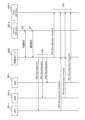
- FIG. 12 is a diagram illustrating an operation example according to the second embodiment.
- FIG. 12 shows an example in which the mobile IAB node 300M hands over from a source parent node (Source Parent) 300-S to a target parent node (Target Parent) 300-T. Further, FIG. 12 shows an example in which the subordinate UE 100 is also handed over in conjunction with the handover of the mobile IAB node 300M.
- the source parent node 300-S and the target parent node 300-T may be intermediate IAB nodes 300S under the donor node 200.
- step S20 the CU of the donor node 200 sets conditional reconfiguration to the UE 100.
- the CU of the donor node 200 generates an RRC message (for example, an RRC reconfiguration (HO command) message) that includes a conditional reconfiguration, and sends the F1 message that includes the RRRC message to the IAB-DU of the mobile IAB node 300M.
- RRC message for example, an RRC reconfiguration (HO command) message
- the IAB-DU of the mobile IAB node 300M extracts an RRC message including conditional reconfiguration from the F1 message and transmits the RRC message to the UE 100.
- the conditional reconfiguration may include multiple entries, with one setting being one entry. At least one of the plurality of entries includes an execution condition "to be executed in response to an execution instruction" (or “to be executed when an execution instruction is received”). As a result, the UE 100 does not start executing the execution condition even after receiving the conditional reconfiguration, but starts executing the execution condition upon receiving an execution instruction from the mobile IAB node 300M, as described above. The operation corresponding to solution 2 becomes possible.
- step S21 the CU of the donor node 200 transmits an execution instruction transmission instruction to the IAB-DU of the mobile IAB node 300M.
- the CU of the donor node 200 may generate an RRC message including a transmission instruction, and transmit the F1 message including the RRC message to the IAB-DU of the mobile IAB node 300M.
- the CU of donor node 200 may send an F1 message including a transmission instruction to the IAB-DU of mobile IAB node 300M.
- the transmission instruction may include the UE identifier of the UE 100 to which the transmission instruction is sent. Further, the transmission instruction may include a conditional reconfiguration identifier to which the transmission instruction is transmitted. The identifier represents, for example, information that instructs at least one of the plurality of conditional reconfigurations to be transmitted. Alternatively, the transmission instruction may include an entry number of a list in the conditional reconfiguration to which the transmission instruction is to be transmitted.
- the transmission instruction may include an instruction to immediately transmit the execution instruction.
- the transmission instruction may include an instruction to transmit an execution instruction when executing a conditional handover.
- the transmission instruction may include an instruction to transmit an execution instruction when performing handover.
- the transmission instruction may include an instruction to transmit an execution instruction when transmitting an RRC Reconfiguration Complete message.
- step S22 the IAB-DU of the mobile IAB node 300M transmits an execution instruction to the UE 100.
- the IAB-DU of the mobile IAB node 300M transmits an execution instruction for the conditional reconfiguration specified in the transmission instruction to the UE 100 specified in the transmission instruction (step S21).
- the execution instruction may be transmitted while being included in a MAC control element (MAC CE).
- the execution instruction may be included in a BAP Control PDU and transmitted.
- the execution instruction also includes a conditional reconfiguration identifier to be executed.
- the identifier represents, for example, information indicating at least one of the plurality of conditional reconfigurations to be executed.
- the execution instruction may include an entry number of a list in the conditional reconfiguration to be executed.
- step S23 the UE 100 executes the specified conditional reconfiguration and executes handover to the target cell.
- the mobile IAB node 300M has been described, but the present invention is not limited thereto.
- the intermediate IAB node 300S can be used instead of the mobile IAB node 300M.
- the UE 100 under the intermediate IAB node 300S executes conditional reconfiguration to change the target cell managed by the intermediate IAB node 300S (or other intermediate IAB node 300S) from the serving cell managed by the intermediate IAB node 300S. It becomes possible to execute handover to the managed target cell).
- the operation example shown in FIG. 12 can be implemented by replacing the mobile IAB node 300M with the intermediate IAB node 300S.
- conditional reconfiguration is set between the UE 100, the mobile IAB node 300M, and the donor node 200 has been described, but the present invention is not limited to this.
- conditional reconfiguration described in the second embodiment is also applicable between the UE 100 and the gNB 200.
- FIG. 13 is a diagram illustrating another example of operation according to the second embodiment.
- the CU of the gNB 200 sets conditional reconfiguration for the UE 100 similarly to the second embodiment (step S25).
- at least one of the entries included in the conditional reconfiguration includes the execution condition "to be executed according to an execution instruction.”
- the UE 100 does not immediately execute the conditional reconfiguration for the entry even if it is set, but waits until receiving an execution instruction.
- the CU of the gNB 200 transmits an execution instruction transmission instruction to the DU of the gNB 200 (step S26).
- the content of the transmission instruction and the information included in the transmission instruction may also be the same as in the second embodiment.
- the DU of the gNB 200 transmits an execution instruction to the UE 100 (step S27).
- the UE 100 starts the instructed execution condition and executes handover to the target cell, similarly to the second embodiment (step S28).
- a group handover is a handover performed simultaneously by a plurality of UEs 100 as one group.
- the mobile IAB node 300M is also included in the group and becomes a handover target.
- FIGS. 14A and 14B are diagrams illustrating an example of group handover operation according to the third embodiment.
- the source donor node (Source IAB-donor) 200-S sends an RRC retransmission command, which is a handover command, to each UE 100-1, ..., 100-n and the mobile IAB node 300M.
- RRC retransmission command which is a handover command
- the source donor node 200-S transmits a group reconfiguration message (including the F1 message) to the mobile IAB node 300M.
- the group reconfiguration message includes, for example, group handover configuration information.
- the group reconfiguration message is, for example, a message indicating a group handover instruction.
- the mobile IAB node 300M sends a group reconfiguration message to each UE 100-1, . . . , 100-n.
- group handover configuration information is transmitted from the source donor node 200-S to the mobile IAB node 300M using one F1 message.
- F1 message an individual message
- group handover can be set for multiple UEs 100-1, . . . , 100-n. Therefore, in the example shown in FIG. 14(B), the load of F1 signaling can be reduced compared to the example shown in FIG. 14(A).
- IAB since F1 signaling is also wireless, it is considered effective to reduce the load of F1 signaling compared to the case where it is performed by wire.
- the mobile IAB node 300M allows connection not only to the UE 100 dedicated to Rel-18 but also to the UE 100 compatible with Rel-17 or earlier. Therefore, at least, it is preferable that the mobile IAB node 300M transmits an RRC reconfiguration message that can be received even by the UE 100 of Rel-17 or earlier, rather than a new RRC reconfiguration message for group handover.
- the mobile IAB node 300M when the mobile IAB node 300M receives the common settings common to the group and the individual settings for each UE from the donor node, the mobile IAB node 300M combines them and creates an RRC that can also be received by the UE 100 of Rel-17 or earlier. An example of transmitting a reconfiguration message to each UE 100 will be described.
- a donor node for example, source donor node 200-S
- a mobile relay node for example, mobile IAB node 300M
- 1 message to the mobile relay node.
- the donor node sends a second message to the mobile relay node, including the individual settings of each user equipment under the mobile relay node.
- the mobile relay node sends an RRC reconfiguration message including common settings and individual settings to each user equipment.
- a message including a common setting can be used to set a common setting to the UEs 100 within the group. Therefore, compared to the case where each message is transmitted to each UE as shown in FIG. 14(A), in the second embodiment, it is possible to reduce F1 signaling.
- the message sent to the UE 100 uses an RRC reconfiguration message that can be received even by the UE 100 of Re-17 or earlier. Therefore, the UE 100 of Re-17 or earlier can also be appropriately connected to the target cell by group handover. Therefore, similarly to the first embodiment, the UE 100 can appropriately connect to the network.
- FIG. 15 is a diagram illustrating an operation example according to the third embodiment.
- the example shown in FIG. 15 represents an example in which the mobile IAB node 300M is handed over from the source donor node (Source IAB-donor) 200-S to the target donor node (Target IAB-donor) 200-T.
- the example shown in FIG. 14 represents an example in which the UEs 100-1, ..., 100-n under the mobile IAB node 300M also form one group and perform group handover in response to the handover of the mobile IAB node 300M.
- a group formed by a plurality of UEs 100-1, . . . , 100-n and in which group handover is performed may be referred to as a "UE group.”
- step S30 the CU of the source donor node 200-S transmits the common settings of the UE group to the IAB-DU of the mobile IAB node 300M.
- the CU of the source donor node 200-S may generate an RRC message (e.g., an RRC reconfiguration message) that includes a common configuration, and send an F1 message that includes the RRC message to the mobile IAB node 300M. .
- the CU of source donor node 200-S may send an F1 message containing the common settings to mobile IAB node 300M. In either case, the F1 message is an example of the first message.
- the common settings include settings common to the UEs 100-1, ..., 100-n belonging to the UE group.
- the setting may be the setting value itself.
- the settings may be represented as information elements (IEs).
- the message including the common settings may include a UE group identifier representing an identifier of the UE group.
- the message including the common settings may include a list of UE identifiers of the UEs 100 belonging to the UE group.
- a UE group identifier and/or a list of UE identifiers may be included in the common configuration.
- step S31 the CU of the source donor node 200-S transmits the individual settings of the UE group to the IAB-DU of the mobile IAB node 300M.
- the CU of the source donor node 200-S may generate an RRC message (e.g., an RRC reconfiguration message) including the personalized configuration, and send an F1 message including the RRC message to the mobile IAB node 300M.
- the CU of source donor node 200-S may send an F1 message containing personalized settings to mobile IAB node 300M.
- the F1 message is an example of the second message.
- the individual settings include individual settings for each UE 100-1, ..., 100-n belonging to the UE group.
- the setting may be the setting value itself.
- the settings may be represented as information elements (IEs).
- the message including the individual settings includes the UE identifier of the UE 100 belonging to the UE group.
- the UE identifier represents the UE 100 that is the target of individual settings.
- the UE identifier may be included in the individual settings.
- step S32 the IAB-DU of the mobile IAB node 300M combines the common settings and the individual settings, and generates an RRC reconfiguration message including the common settings and the individual settings.
- the RRC reconfiguration message is an RRC reconfiguration message that can also be received by the UE 100 of Rel-17 or earlier.
- the settings of the individual settings are given priority, so that the same settings are included in both the common settings and the individual settings. may be excluded from the list.
- the IAB-DU of the mobile IAB node 300M transmits the generated RRC reconfiguration message to each UE 100-1, ..., 100-n belonging to the UE group.
- step S33 the IAB-MT of the mobile IAB node 300M and each UE 100-1,..., 100-n transmit an RRC reconfiguration completion message to the target donor node (Target IAB-donor) 200-T. and complete the group handover.
- Target IAB-donor target donor node
- FIG. 16 is a diagram illustrating another example of operation according to the third embodiment.
- FIG. 16 shows an example in which UEs 100-1, ..., 100-n under gNB 200 form a UE group, and group handover is performed among the UEs 100-1, ..., 100-n.
- the CU of the gNB 200 transmits the common settings to the DU of the gNB 200 (step S35).
- the CU of the gNB 200 may generate an RRC message (for example, an RRC reconfiguration message) including the common settings, and transmit the F1 message including the RRC message to the DU of the gNB 200.
- the CU of the gNB 200 may transmit the F1 message including the common settings to the DU of the gNB 200, similarly to the third embodiment.
- the common settings themselves may be the same as in the third operation example.
- the CU of the gNB 200 transmits the individual settings to the DU of the gNB 200 (step S36).
- the CU of the gNB 200 may generate an RRC message (for example, an RRC reconfiguration message) including the individual settings, and transmit the F1 message including the RRC message to the DU of the gNB 200.
- the CU of the gNB 200 may transmit the F1 message including the individual settings to the DU of the gNB 200, similarly to the third embodiment.
- the individual settings themselves may be the same as in the third embodiment.
- the DU of the gNB 200 combines the common settings and the individual settings and transmits an RRC reconfiguration message including the common settings and the individual settings to each UE 100-1, ..., 100-n (step S38).
- the RRC reconfiguration message is an RRC reconfiguration message that can be received even in the UE 100 of Rel-17 or earlier.
- Each UE 100-1, . . . , 100-n transmits an RRC reconfiguration completion message to the target cell and completes the handover (step S38).
- a program that causes a computer to execute each process performed by the UE 100, gNB 200, or IAB node 300 may be provided.
- the program may be recorded on a computer readable medium.
- Computer-readable media allow programs to be installed on a computer.
- the computer-readable medium on which the program is recorded may be a non-transitory recording medium.
- the non-transitory recording medium is not particularly limited, but may be a recording medium such as a CD-ROM or a DVD-ROM.
- the circuits that execute each process performed by the UE 100, gNB 200, or IAB node 300 may be integrated, and at least a portion of the UE 100 or gNB 200 may be configured as a semiconductor integrated circuit (chip set, SoC: System on a chip). .
- the terms “based on” and “depending on” refer to “based solely on” and “depending solely on,” unless expressly stated otherwise. ” does not mean. Reference to “based on” means both “based solely on” and “based at least in part on.” Similarly, the phrase “in accordance with” means both “in accordance with” and “in accordance with, at least in part.” Furthermore, the terms “include” and “comprise” do not mean to include only the listed items, and may include only the listed items, or may include additional items in addition to the listed items. This means that it may include. Also, as used in this disclosure, the term “or” is not intended to be exclusive OR. Furthermore, any reference to elements using the designations "first,” “second,” etc.
- a communication control method used in a cellular communication system comprising: A communication control method comprising the step of a base station transmitting conditional reconfiguration including permission information indicating whether or not connection by RACHless handover is permitted for each target cell to a user equipment.
- the mobile relay node further comprises the step of transmitting combination information representing a combination of cells connectable by the RACHless handover to the donor node,
- the step of transmitting the conditional reconfiguration includes the step of the base station transmitting the conditional reconfiguration based on the combination information.
- the communication control method according to supplementary note 1 or supplementary note 2.
- a communication control method used in a cellular communication system comprising: a step in which the donor node transmits conditional reconfiguration including execution conditions to be executed upon receiving an execution instruction to a user device under the mobile relay node; the donor node transmitting a transmission instruction instructing transmission of the execution instruction to the mobile relay node; A communication control method, comprising the step of the mobile relay node transmitting the execution instruction to the user device in response to receiving the transmission instruction.
- the step of transmitting the execution instruction includes the step of the mobile relay node transmitting the execution instruction including information indicating whether at least one of the plurality of conditional reconfigurations should be executed. Including the communication control method described in Appendix 5.
- a communication control method used in a cellular communication system comprising: a donor node transmitting a first message including common settings common to a plurality of user devices under the mobile relay node to the mobile relay node; the donor node transmitting, to the mobile relay node, a second message including individual settings of each of the user equipments under the mobile relay node;
- a communication control method comprising the step of: the mobile relay node transmitting an RRC reconfiguration message including the common settings and the individual settings to each of the user equipments.
- the detailed objectives of this work item are as follows. - Define migration/topology adaptation procedures to enable mobility of IAB nodes. This also includes inter-donor migration (complete migration) of the entire mobile IAB node. - Enhance the mobility of IAB nodes and their served UEs. This includes aspects related to group mobility. There is no optimization targeted at surrounding UEs. Note: Solutions should not touch on topics that are already discussed in Rel-17 or have been excluded from Rel-17, except for enhancements specific to IAB node mobility. There is a need. - It is necessary to alleviate interference due to the mobility of IAB nodes, for example to avoid collisions of reference signals and control signals (PCI, RACH, etc.).
- PCI reference signals and control signals
- RAN3 and RAN2 will discuss the potential complications between scenarios where a mobile IAB node connects to a stationary (intermediate) IAB node and a scenario where a mobile IAB node connects directly to an IAB donor. It should be discussed.
- Group Reconfiguration Group UE mobility is expected as one of the possible enhancements of mobile IAB. This is because when a mobile IAB node moves to a new IAB donor, many UEs need to be handed over at the same time.
- handover is indicated by dedicated signaling, namely RRC reconfiguration and synchronization.
- RRC reconfiguration and synchronization.
- group reconfiguration may be considered as a candidate for reducing signaling overhead and delay. This is expected to reconfigure multiple UEs with one message.
- Proposal 2 Maintain the current CRRRC structure and do not advance a common RRC structure (i.e., no impact on RRCCR).
- RAN2 assumes that RRC will continue to use the dedicated UE configuration if agreed.
- F1 signal reduction is also more useful for mobile IAB than MBS, but since backhaul links are generally assumed on FR2, access link signal reduction is still more important.
- WID clearly states that ⁇ resolutions, except for improvements specific to IAB node mobility, do not address where Rel-17 discussions have already taken place and the topic has been excluded from Rel-17.'' RAN2 does not need to reopen group reconfiguration (or common RRC structure) in the Rel-18 mobile IAB, at least from RAN2's point of view.
- Proposal 1 The RAN2 should agree to only use individual RRC reconfiguration as is currently the case for UE handovers due to movement of mobile IAB nodes.
- RAN3 had two solutions for reducing service interruptions during donor-to-donor IAB node migration in Rel-17. Among them, solution 1 is shown in FIG.
- solution 1 the IAB-DU suspends the RRC reconfiguration message to the child node upon handover completion.
- RAN2 concluded that both solutions require further discussion, but determined that Solution 1 had less overall impact than Solution 2.
- the UE handover can also be performed without Solution 1.
- Solution 1 for intra-donor migration is reused to reduce service interruption for legacy UEs during inter-donor mobile IAB node migration.
- Proposal 2 RAN2 should assume that Solution 1 for reducing service interruption during Rel-17 intra-donor IAB node migration can be reused for legacy UE handover.
- Conditional Reconfiguration If individual RRC reconfigurations are sent to the UE simultaneously, many RRC messages and their corresponding responses may increase the radio resource load. Conditional reconfiguration is considered useful for load balancing, ie time domain distribution. This is so that the IAB donor can avoid sending many simultaneous messages by pre-reconfiguring the IAB node while the IAB donor is moving. There is a similar solution in Solution 2 for Rel-17 service interruption reduction.
- Conditional reconfiguration may help IAB donors distribute RRC reconfiguration messages in the time domain.
- the mobile IAB-DU may need to change its cell ID after the migration of the mobile IAB node. It will be done. For example, if the target topology requires changes to avoid PCI conflicts. In this case, the UE also needs to move from the old cell (the cell that disappears) to the new cell (the cell that becomes available), but both cells are managed by the same mobile IAB-DU. For such "cell shifts", conditional reconfiguration is considered more effective than conventional HO commands.
- conditional reconfiguration may work efficiently.
- Proposal 3 RAN2 should consider whether conditional reconfiguration to the UE can be enhanced for improved mobility of mobile IAB nodes.
- the UE must first initiate a random access procedure upon receiving the HO command.
- the target cell is the same as the source cell, ie, the same IAB-DU serves both cells, only the cell ID may be different.
- the timing advance is also the same in both cells, so no PRACH transmission is required.
- RAN2 should consider whether to specify RACH-less handover to improve the mobility of mobile IABs. Note that RACH-less handover applies only to Rel-18 UEs.
- Proposal 4 RAN2 should consider whether RACH-less handover of Rel-18 UE is useful due to the movement of mobile IAB nodes.
- the WID justification part states the assumption that "the mobile IAB node has no descendant IAB nodes, ie only serves UEs". Therefore, such an assumption should be confirmed by RAN2.
- Proposal 5 RAN2 should ensure that the mobile IAB node is always the access IAB node and therefore ensure that packet loss due to hop-by-hop ARQ is a rare case in Rel-18 mobile IAB. be.
- the UE's PDCP sublayer can handle data recovery as it does today. Therefore, no improvements are planned for lossless handover of UEs due to movement of mobile IAB nodes.
- Proposal 6 RAN2 should agree that the existing UE PDCP data recovery can be used in lossless handover due to movement of the mobile IAB node, i.e. no improvement is required.
- WID states that mobile IAB nodes only support UEs.
- a mobile IAB node has no child nodes, i.e. it needs to support only UEs.
- Proposal 7 RAN2 should agree to write in the Stage-2 specification that when acting as a mobile IAB node in this release, the IAB node should not set the IAB support IE in the SIB.
Landscapes
- Engineering & Computer Science (AREA)
- Computer Networks & Wireless Communication (AREA)
- Signal Processing (AREA)
- Mobile Radio Communication Systems (AREA)
Priority Applications (1)
| Application Number | Priority Date | Filing Date | Title |
|---|---|---|---|
| JP2024540465A JP7761768B2 (ja) | 2022-08-08 | 2023-08-07 | 通信制御方法 |
Applications Claiming Priority (2)
| Application Number | Priority Date | Filing Date | Title |
|---|---|---|---|
| US202263395940P | 2022-08-08 | 2022-08-08 | |
| US63/395,940 | 2022-08-08 |
Publications (1)
| Publication Number | Publication Date |
|---|---|
| WO2024034570A1 true WO2024034570A1 (ja) | 2024-02-15 |
Family
ID=89851833
Family Applications (1)
| Application Number | Title | Priority Date | Filing Date |
|---|---|---|---|
| PCT/JP2023/028764 Ceased WO2024034570A1 (ja) | 2022-08-08 | 2023-08-07 | 通信制御方法 |
Country Status (3)
| Country | Link |
|---|---|
| US (1) | US20250184838A1 (https=) |
| JP (1) | JP7761768B2 (https=) |
| WO (1) | WO2024034570A1 (https=) |
Families Citing this family (1)
| Publication number | Priority date | Publication date | Assignee | Title |
|---|---|---|---|---|
| US12532234B2 (en) * | 2022-12-09 | 2026-01-20 | Rakuten Symphony, Inc. | Prioritizing random access channel-less layer 1/layer 2 triggered mobility |
Citations (1)
| Publication number | Priority date | Publication date | Assignee | Title |
|---|---|---|---|---|
| WO2022079296A2 (en) * | 2020-10-16 | 2022-04-21 | Fraunhofer-Gesellschaft zur Förderung der angewandten Forschung e.V. | Iab link failure |
Family Cites Families (3)
| Publication number | Priority date | Publication date | Assignee | Title |
|---|---|---|---|---|
| JP7305780B2 (ja) | 2019-10-03 | 2023-07-10 | 京セラ株式会社 | 通信制御方法及びユーザ装置 |
| WO2021141386A1 (en) | 2020-01-06 | 2021-07-15 | Lg Electronics Inc. | Method and apparatus for mobility execution in wireless communication system |
| US20240049097A1 (en) | 2021-01-08 | 2024-02-08 | Nokia Technologies Oy | Methods, apparatuses, and computer program products for fast cell selection using conditional handover and intercell beam management reporting |
-
2023
- 2023-08-07 WO PCT/JP2023/028764 patent/WO2024034570A1/ja not_active Ceased
- 2023-08-07 JP JP2024540465A patent/JP7761768B2/ja active Active
-
2025
- 2025-02-07 US US19/048,261 patent/US20250184838A1/en active Pending
Patent Citations (1)
| Publication number | Priority date | Publication date | Assignee | Title |
|---|---|---|---|---|
| WO2022079296A2 (en) * | 2020-10-16 | 2022-04-21 | Fraunhofer-Gesellschaft zur Förderung der angewandten Forschung e.V. | Iab link failure |
Non-Patent Citations (5)
| Title |
|---|
| FUJITSU: "CHO for UE or IAB-MT on migration", 3GPP DRAFT; R2-2009007, 3RD GENERATION PARTNERSHIP PROJECT (3GPP), MOBILE COMPETENCE CENTRE ; 650, ROUTE DES LUCIOLES ; F-06921 SOPHIA-ANTIPOLIS CEDEX ; FRANCE, vol. RAN WG2, no. electronic; 20201102 - 20201113, 23 October 2020 (2020-10-23), Mobile Competence Centre ; 650, route des Lucioles ; F-06921 Sophia-Antipolis Cedex ; France , XP051942052 * |
| HUAWEI: "Inter-donor-CU handover procedure analysis", 3GPP DRAFT; R3-205292, 3RD GENERATION PARTNERSHIP PROJECT (3GPP), MOBILE COMPETENCE CENTRE ; 650, ROUTE DES LUCIOLES ; F-06921 SOPHIA-ANTIPOLIS CEDEX ; FRANCE, vol. RAN WG3, no. Online; 20200817 - 20200828, 7 August 2020 (2020-08-07), Mobile Competence Centre ; 650, route des Lucioles ; F-06921 Sophia-Antipolis Cedex ; France , XP051915958 * |
| INTERDIGITAL INC.: "Details of Conditional Handover Procedure for NR", 3GPP DRAFT; R2-1903561 (R16 NR MOB WI AI1193 DETAILS OF CHO), 3RD GENERATION PARTNERSHIP PROJECT (3GPP), MOBILE COMPETENCE CENTRE ; 650, ROUTE DES LUCIOLES ; F-06921 SOPHIA-ANTIPOLIS CEDEX ; FRANCE, vol. RAN WG2, no. Xi'an, China; 20190408 - 20190412, 6 April 2019 (2019-04-06), Mobile Competence Centre ; 650, route des Lucioles ; F-06921 Sophia-Antipolis Cedex ; France , XP051700904 * |
| KYOCERA: "Mobility enhancements for mobile IAB", 3GPP DRAFT; R2-2210429, 3RD GENERATION PARTNERSHIP PROJECT (3GPP), MOBILE COMPETENCE CENTRE ; 650, ROUTE DES LUCIOLES ; F-06921 SOPHIA-ANTIPOLIS CEDEX ; FRANCE, vol. RAN WG2, no. Online; 20221010 - 20221019, 30 September 2022 (2022-09-30), Mobile Competence Centre ; 650, route des Lucioles ; F-06921 Sophia-Antipolis Cedex ; France, XP052263748 * |
| KYOCERA: "UE handover aspects for mobile IAB", 3GPP DRAFT; R2-2208292, 3RD GENERATION PARTNERSHIP PROJECT (3GPP), MOBILE COMPETENCE CENTRE ; 650, ROUTE DES LUCIOLES ; F-06921 SOPHIA-ANTIPOLIS CEDEX ; FRANCE, vol. RAN WG2, no. Online; 20220817 - 20220829, 10 August 2022 (2022-08-10), Mobile Competence Centre ; 650, route des Lucioles ; F-06921 Sophia-Antipolis Cedex ; France, XP052261603 * |
Also Published As
| Publication number | Publication date |
|---|---|
| JPWO2024034570A1 (https=) | 2024-02-15 |
| JP7761768B2 (ja) | 2025-10-28 |
| US20250184838A1 (en) | 2025-06-05 |
Similar Documents
| Publication | Publication Date | Title |
|---|---|---|
| JP7212112B2 (ja) | 移動通信システム、中継ノード、及び基地局 | |
| JP6405454B2 (ja) | ユーザー装置の基地局ハンドオーバ方法及び基地局、ユーザー装置 | |
| CN110892743B (zh) | 用于使用户平面中断延迟最小化的方法和无线装置 | |
| EP3035735B1 (en) | Handover method, master base station and slave base station | |
| JP5448219B2 (ja) | コードレス通信システムでハンドオーバー装置及び方法 | |
| EP2744260B1 (en) | Data transmission method and device | |
| JP7814477B2 (ja) | 通信制御方法、第1ドナー基地局、及びシステム | |
| JP7189219B2 (ja) | 中継装置 | |
| JP6480637B2 (ja) | 通信方法、プロセッサ、及びユーザ装置 | |
| JP7453479B2 (ja) | 通信制御方法 | |
| US10820239B2 (en) | Communication method, processor, base station, and network apparatus | |
| JP7790628B2 (ja) | ネットワークノードの通信方法、移動ノードの通信方法、移動ノード及びドナー機器 | |
| US20240031880A1 (en) | Integrated access and backhaul donor migration methods and systems | |
| JPWO2016167212A1 (ja) | 基地局及び通信制御方法 | |
| JP7483876B2 (ja) | 通信制御方法 | |
| US20230328607A1 (en) | Communication control method | |
| WO2024070923A1 (ja) | 通信制御方法 | |
| US20250184838A1 (en) | Communication control method | |
| US20250024339A1 (en) | Method, apparatus and system relating to a dual active protocol stack | |
| US20250184844A1 (en) | Communication control method | |
| CN119586092A (zh) | 通过促进切换来确保服务连续性 | |
| WO2024036491A1 (en) | Assurance of service continuity by completing handovers | |
| US20240306230A1 (en) | Method and apparatus for ue-to-ue relay transmitting sidelink ue information in a wireless communication system | |
| WO2024029521A1 (ja) | 通信制御方法 | |
| WO2024029520A1 (ja) | 通信制御方法 |
Legal Events
| Date | Code | Title | Description |
|---|---|---|---|
| 121 | Ep: the epo has been informed by wipo that ep was designated in this application |
Ref document number: 23852532 Country of ref document: EP Kind code of ref document: A1 |
|
| WWE | Wipo information: entry into national phase |
Ref document number: 2024540465 Country of ref document: JP |
|
| NENP | Non-entry into the national phase |
Ref country code: DE |
|
| 122 | Ep: pct application non-entry in european phase |
Ref document number: 23852532 Country of ref document: EP Kind code of ref document: A1 |