WO2024029366A1 - 双極型蓄電池 - Google Patents
双極型蓄電池 Download PDFInfo
- Publication number
- WO2024029366A1 WO2024029366A1 PCT/JP2023/026672 JP2023026672W WO2024029366A1 WO 2024029366 A1 WO2024029366 A1 WO 2024029366A1 JP 2023026672 W JP2023026672 W JP 2023026672W WO 2024029366 A1 WO2024029366 A1 WO 2024029366A1
- Authority
- WO
- WIPO (PCT)
- Prior art keywords
- active material
- positive electrode
- material layer
- negative electrode
- bone
- Prior art date
- Legal status (The legal status is an assumption and is not a legal conclusion. Google has not performed a legal analysis and makes no representation as to the accuracy of the status listed.)
- Ceased
Links
Images

Classifications
-
- H—ELECTRICITY
- H01—ELECTRIC ELEMENTS
- H01M—PROCESSES OR MEANS, e.g. BATTERIES, FOR THE DIRECT CONVERSION OF CHEMICAL ENERGY INTO ELECTRICAL ENERGY
- H01M10/00—Secondary cells; Manufacture thereof
- H01M10/06—Lead-acid accumulators
- H01M10/12—Construction or manufacture
-
- H—ELECTRICITY
- H01—ELECTRIC ELEMENTS
- H01M—PROCESSES OR MEANS, e.g. BATTERIES, FOR THE DIRECT CONVERSION OF CHEMICAL ENERGY INTO ELECTRICAL ENERGY
- H01M10/00—Secondary cells; Manufacture thereof
- H01M10/06—Lead-acid accumulators
- H01M10/18—Lead-acid accumulators with bipolar electrodes
-
- H—ELECTRICITY
- H01—ELECTRIC ELEMENTS
- H01M—PROCESSES OR MEANS, e.g. BATTERIES, FOR THE DIRECT CONVERSION OF CHEMICAL ENERGY INTO ELECTRICAL ENERGY
- H01M4/00—Electrodes
- H01M4/02—Electrodes composed of, or comprising, active material
- H01M4/14—Electrodes for lead-acid accumulators
-
- H—ELECTRICITY
- H01—ELECTRIC ELEMENTS
- H01M—PROCESSES OR MEANS, e.g. BATTERIES, FOR THE DIRECT CONVERSION OF CHEMICAL ENERGY INTO ELECTRICAL ENERGY
- H01M4/00—Electrodes
- H01M4/02—Electrodes composed of, or comprising, active material
- H01M4/64—Carriers or collectors
- H01M4/66—Selection of materials
- H01M4/68—Selection of materials for use in lead-acid accumulators
-
- H—ELECTRICITY
- H01—ELECTRIC ELEMENTS
- H01M—PROCESSES OR MEANS, e.g. BATTERIES, FOR THE DIRECT CONVERSION OF CHEMICAL ENERGY INTO ELECTRICAL ENERGY
- H01M4/00—Electrodes
- H01M4/02—Electrodes composed of, or comprising, active material
- H01M4/64—Carriers or collectors
- H01M4/70—Carriers or collectors characterised by shape or form
- H01M4/72—Grids
- H01M4/73—Grids for lead-acid accumulators, e.g. frame plates
-
- H—ELECTRICITY
- H01—ELECTRIC ELEMENTS
- H01M—PROCESSES OR MEANS, e.g. BATTERIES, FOR THE DIRECT CONVERSION OF CHEMICAL ENERGY INTO ELECTRICAL ENERGY
- H01M50/00—Constructional details or processes of manufacture of the non-active parts of electrochemical cells other than fuel cells, e.g. hybrid cells
- H01M50/10—Primary casings; Jackets or wrappings
- H01M50/102—Primary casings; Jackets or wrappings characterised by their shape or physical structure
- H01M50/103—Primary casings; Jackets or wrappings characterised by their shape or physical structure prismatic or rectangular
-
- H—ELECTRICITY
- H01—ELECTRIC ELEMENTS
- H01M—PROCESSES OR MEANS, e.g. BATTERIES, FOR THE DIRECT CONVERSION OF CHEMICAL ENERGY INTO ELECTRICAL ENERGY
- H01M50/00—Constructional details or processes of manufacture of the non-active parts of electrochemical cells other than fuel cells, e.g. hybrid cells
- H01M50/10—Primary casings; Jackets or wrappings
- H01M50/183—Sealing members
- H01M50/184—Sealing members characterised by their shape or structure
-
- H—ELECTRICITY
- H01—ELECTRIC ELEMENTS
- H01M—PROCESSES OR MEANS, e.g. BATTERIES, FOR THE DIRECT CONVERSION OF CHEMICAL ENERGY INTO ELECTRICAL ENERGY
- H01M50/00—Constructional details or processes of manufacture of the non-active parts of electrochemical cells other than fuel cells, e.g. hybrid cells
- H01M50/10—Primary casings; Jackets or wrappings
- H01M50/183—Sealing members
- H01M50/186—Sealing members characterised by the disposition of the sealing members
Definitions
- Embodiments of the present invention relate to bipolar storage batteries.
- a substrate made of resin is attached to the inside of a frame (rim) made of resin in the shape of a picture frame.
- a positive electrode current collector and a negative electrode current collector are provided on one side and the other side of the substrate.
- a positive electrode active material layer is adjacent to the positive electrode current collector.
- a negative electrode active material layer is adjacent to the negative electrode current collector. Together, these constitute a bipolar plate.
- a glass mat (electrolytic layer) containing an electrolytic solution is disposed inside the frame-shaped spacer made of resin. A plurality of frames and spacers are alternately stacked and assembled.
- the amount of material in the active material layer is large. Therefore, it becomes difficult to bring the active material layer (positive electrode active material layer, negative electrode active material layer) into close contact with the positive electrode current collector or negative electrode current collector while retaining the active material. There may also be cases.
- a lattice substrate made of a lead alloy filled with an active material which is used in ordinary lead-acid batteries.
- an oxidation reaction occurs between the lead of the grid substrate and the active material during the aging and drying process of the active material. This oxidation reaction is accompanied by the generation of oxidation reaction heat, but the oxidation reaction heat causes rapid drying of the active material, which may cause cracks (active material cracks) to occur in the active material.
- the lattice substrate itself has a corresponding size, the weight of the entire storage battery may increase, which may lead to a decrease in the capacity of the active material. Therefore, from the viewpoint of reducing the overall weight and space of the storage battery, we have no choice but to hesitate in adopting it.
- the present invention retention of the filled active material is appropriately maintained while avoiding the occurrence of a reaction that generates heat between the active material and the current collector for the positive electrode and the current collector for the negative electrode.
- the purpose of the present invention is to provide a bipolar storage battery that can ensure adhesion.
- a bipolar storage battery includes a positive electrode having a positive electrode current collector and a positive electrode active material layer, a negative electrode having a negative electrode current collector and a negative electrode active material layer, and a negative electrode between the positive electrode and the negative electrode. Covers at least one of the positive electrode side and the negative electrode side of the cell member, including an intervening separator and forming a plurality of spaces for individually accommodating the cell member and the plurality of cell members stacked at intervals.
- the positive electrode active material layer and the negative electrode active material layer each have an active material
- Both or one of the active material layers for use has an active material holder that holds the active material
- the active material holder has a thickness direction of the active material layer for the positive electrode or the active material layer for the negative electrode.
- a plurality of first bones and a plurality of first bones are disposed inside the positive electrode active material layer or the negative electrode active material layer and are formed of a material that is chemically non-bonded and non-reactive with the active material. It includes a plurality of second bones that intersect with the first bone.
- a positive electrode having a positive electrode current collector and a positive electrode active material layer, a negative electrode having a negative electrode current collector and a negative electrode active material layer, and a positive electrode and a negative electrode having a positive electrode current collector and a negative electrode active material layer.
- At least one of the positive electrode side and the negative electrode side of the cell member which includes a separator interposed between the cell members and is stacked at intervals, and forms a plurality of spaces that individually accommodate the plurality of cell members.
- the positive electrode active material layer and the negative electrode active material layer each have an active material, and the positive electrode active material layer
- the active material layer for the positive electrode or the active material layer for the negative electrode has an active material holder that holds the active material, and the active material holder has the thickness of the active material layer for the positive electrode or the active material layer for the negative electrode.
- a plurality of first bones are disposed inside the positive electrode active material layer or the negative electrode active material layer, and are formed of a material that is chemically non-bonded and non-reactive with the active material.
- a plurality of second bones intersect with a plurality of first bones.
- FIG. 1 is a cross-sectional view showing the structure of a bipolar lead-acid battery according to an embodiment of the present invention.
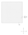
- FIG. 2 is an explanatory diagram showing the entire active material layer including an active material holder in a bipolar lead-acid battery according to an embodiment of the present invention.
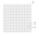
- FIG. 1 is an explanatory diagram showing the entire active material holder according to an embodiment of the present invention.
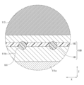
- FIG. 2 is a partially enlarged view showing an enlarged area surrounded by a broken circle in the cross-sectional view of FIG. 1;
- FIG. 1 is a cross-sectional view showing the structure of a bipolar lead-acid battery 100 according to an embodiment of the present invention.
- a bipolar lead-acid battery 100 includes a plurality of cell members 110, a plurality of bipolar plates (space forming members) 120, and a first end plate (space forming member). ) 130 and a second end plate (space forming member) 140.
- FIG. 1 shows a bipolar lead-acid battery 100 in which three cell members 110 are stacked
- the number of cell members 110 is determined by the battery design. Further, the number of bipolar plates 120 is determined according to the number of cell members 110.
- the stacking direction of the cell members 110 is assumed to be the Z direction (vertical direction in FIG. 1). Furthermore, directions perpendicular to the Z direction and mutually perpendicular to each other are defined as the X direction and the Y direction.
- the cell member 110 includes a positive electrode 111, a negative electrode 112, and an electrolyte layer (separator) 113.
- the positive electrode 111 includes a positive electrode lead foil 111a, which is a positive electrode current collector made of lead or a lead alloy, and a positive electrode active material layer 111b.
- the negative electrode 112 includes a negative electrode lead foil 112a, which is a negative electrode current collector made of lead or a lead alloy, and a negative electrode active material layer 112b.
- This positive electrode lead foil 111a is bipolarized by an adhesive 150, which will be described later, provided between one surface of the bipolar plate 120 (in the drawing of FIG. 1, the surface facing upward in the paper) and the positive electrode lead foil 111a. It is provided on one side of the plate 120. Therefore, on one surface of the bipolar plate 120, an adhesive layer (adhesive 150), a positive electrode lead foil 111a, and a positive electrode active material layer 111b are laminated in this order.
- the negative electrode lead foil 112a is attached to the bipolar plate by an adhesive 150, which will be described later, provided between the other surface of the bipolar plate 120 (in the drawing of FIG. 1, the surface facing downward in the paper) and the negative electrode lead foil 112a. 120 is provided on the other surface. Therefore, on the other surface of the bipolar plate 120, an adhesive layer (adhesive 150), a negative electrode lead foil 112a, and a negative electrode active material layer 112b are laminated in this order.
- the positive electrode 111 and the negative electrode 112 are electrically connected via a conductor 160, which will be described later.
- the separator 113 is made of, for example, a glass fiber mat impregnated with an electrolytic solution containing sulfuric acid.
- the separator 113 is provided so as to be sandwiched between a positive electrode active material layer 111b provided on one bipolar plate 120 facing each other and a negative electrode active material layer 112b provided on the other bipolar plate 120.
- the positive electrode lead foil 111a, the positive electrode active material layer 111b, the separator 113, the negative electrode active material layer 112b, and the negative electrode lead foil 112a are laminated in this order.
- the bipolar plate 120, the positive electrode lead foil 111a, the positive electrode active material layer 111b, the negative electrode lead foil 112a, and the negative electrode A bipolar electrode is configured by the active material layer 112b.
- a bipolar electrode is an electrode that has the functions of both a positive electrode and a negative electrode.
- the bipolar lead-acid battery 100 is provided in a pair with a cell member 110 having a separator 113 interposed between a positive electrode 111 and a negative electrode 112, with the cell member 110 sandwiched therebetween.
- a plurality of bipolar plates 120 are stacked.
- the dimensions of the positive electrode lead foil 111a in the X and Y directions are larger than the dimensions of the positive electrode active material layer 111b in the X and Y directions.
- the dimensions of the negative electrode lead foil 112a in the X and Y directions are larger than the dimensions of the negative electrode active material layer 112b in the X and Y directions.
- the dimension (thickness) in the Z direction is larger (thicker) in the positive electrode lead foil 111a than in the negative electrode lead foil 112a.
- the dimension (thickness) in the Z direction is larger (thicker) in the positive electrode active material layer 111b than in the negative electrode active material layer 112b.
- the plurality of cell members 110 are stacked at intervals in the Z direction, and the substrate 121 of the bipolar plate 120 is disposed at this interval. That is, the plurality of cell members 110 are stacked with the substrate 121 of the bipolar plate 120 sandwiched therebetween.
- the plurality of bipolar plates 120, the first end plate 130, and the second end plate 140 form spaces for forming a plurality of spaces (cells) C that individually accommodate the plurality of cell members 110. It is a member.
- the bipolar plate 120 is a space forming member that includes a substrate 121 and a frame 122.
- the substrate 121 covers both the positive electrode 111 side and the negative electrode 112 side of the cell member 110, and has a rectangular planar shape.
- the frame 122 surrounds the side surfaces of the cell member 110 and covers the four end faces of the substrate 121.
- the bipolar plate 120 further includes column parts 123 that protrude perpendicularly from both sides of the substrate 121.
- the number of pillar portions 123 protruding from each surface of the substrate 121 may be one or more.
- the substrate 121, frame body 122, and pillar portion 123 that constitute the bipolar plate 120 are integrally formed of, for example, thermoplastic resin.
- thermoplastic resin forming the bipolar plate 120 include acrylonitrile-butadiene-styrene copolymer (ABS resin) and polypropylene. These thermoplastic resins have excellent moldability and sulfuric acid resistance. Therefore, even if the electrolytic solution comes into contact with the bipolar plate 120, the bipolar plate 120 is unlikely to be decomposed, deteriorated, corroded, or the like.
- the dimensions of the frame 122 are larger than the dimensions (thickness) of the substrate 121, and the dimensions between the protruding end surfaces of the pillars 123 are the same as the dimensions of the frame 122.
- a space C is formed between the substrates 121 by stacking the plurality of bipolar plates 120 with the frame bodies 122 and columnar portions 123 in contact with each other. The dimension of the space C in the Z direction is maintained by the pillar portions 123 that are in contact with each other.
- the positive electrode lead foil 111a, the positive electrode active material layer 111b, the negative electrode lead foil 112a, the negative electrode active material layer 112b, and the separator 113 have through holes 111c, 111d, 112c, 112d, and 113a through which the column parts 123 penetrate. each formed.
- the substrate 121 of the bipolar plate 120 has a plurality of through holes 121a passing through the plate surface.
- a first recess 121b is formed on one surface of the substrate 121, and a second recess 121c is formed on the other surface.
- the depth of the first recess 121b is deeper than the depth of the second recess 121c.
- the dimensions of the first recess 121b and the second recess 121c in the X and Y directions correspond to the dimensions of the positive electrode lead foil 111a and the negative electrode lead foil 112a in the X and Y directions.
- the substrate 121 of the bipolar plate 120 is arranged between adjacent cell members 110 in the Z direction. Then, the positive electrode lead foil 111a of the cell member 110 is placed in the first recess 121b of the substrate 121 of the bipolar plate 120 via an adhesive 150. Further, the negative electrode lead foil 112a of the cell member 110 is placed in the second recess 121c of the substrate 121 of the bipolar plate 120 via an adhesive 150.
- a conductor 160 is arranged in the through hole 121a of the substrate 121 of the bipolar plate 120. Both end surfaces of the conductor 160 are in contact with and bonded to the positive electrode lead foil 111a and the negative electrode lead foil 112a. That is, the conductor 160 electrically connects the positive electrode lead foil 111a and the negative electrode lead foil 112a. As a result, all of the plurality of cell members 110 are electrically connected in series.
- a cover plate 170 is provided at the outer edge of the positive electrode lead foil 111a to cover the outer edge.
- the cover plate 170 is, for example, a thin plate-like frame and has rectangular inner and outer lines.
- the inner edge of the cover plate 170 overlaps with the outer edge of the positive electrode lead foil 111a, and the outer edge of the cover plate 170 overlaps with the peripheral edge of the first recess 121b on one surface of the substrate 121.
- the rectangle that forms the inner line of the cover plate 170 is smaller than the rectangle that forms the outer line of the positive electrode lead foil 111a, and the rectangle that forms the outer line of the cover plate 170 is the rectangle that forms the opening surface of the first recess 121b. bigger.
- the adhesive 150 extends from the end surface of the positive electrode lead foil 111a to the outer edge of the opening side of the first recess 121b, and is disposed between the inner edge of the cover plate 170 and the outer edge of the positive electrode lead foil 111a. Ru. The adhesive 150 is also placed between the outer edge of the cover plate 170 and one surface of the substrate 121.
- the cover plate 170 is fixed by adhesive 150 across the peripheral edge of the first recess 121b on one surface of the substrate 121 and the outer edge of the positive electrode lead foil 111a.
- the positive electrode lead foil 111a and the cover plate 170 are fixed to each other through an adhesive 150 so as to face each other.
- the outer edge of the positive electrode lead foil 111a is covered with the cover plate 170 even at the boundary with the peripheral edge of the first recess 121b.
- the cover plate 170 it is more preferable that it be placed so as to be pressed against the positive electrode lead foil 111a.
- the outer edge of the negative lead foil 112a may also be covered with a cover plate similar to the cover plate 170 covering the outer edge of the positive lead foil 111a.
- the cover plate has been explained using a thin plate-like frame as an example, it may also be a tape-like material, for example, as long as it is resistant to electrolytes (sulfuric acid). .
- both or one of the positive electrode active material layer 111b and the negative electrode active material layer 112b is an active material holder 180 that holds an active material. have.
- An active material holder 180 is provided between the active materials when viewed from the thickness direction (Z direction).
- the active material holder 180 may be provided only in either the positive electrode active material layer 111b or the negative electrode active material layer 112b.
- FIG. 2 is an explanatory diagram showing the entire active material layer including the active material holder 180 in the bipolar lead-acid battery 100 according to the embodiment of the present invention.
- FIG. 3 is an explanatory diagram showing the entire active material holder 180 according to the embodiment of the present invention.
- the active material layer shown in FIG. 2 may be either the positive electrode active material layer 111b or the negative electrode active material layer 112b, but for convenience of explanation, the positive electrode active material layer 111b is taken as an example. I will explain. Therefore, the following explanation also applies to the negative electrode active material layer 112b.
- the positive electrode active material layer 111b shown in FIG. 2 is a view seen from above in the stacking direction of the bipolar plate 120. Therefore, in the paper of FIG. 2, the horizontal direction is the X direction, the vertical direction is the Y direction, and the depth direction is the Z direction, which is the stacking direction.
- the positive electrode active material layer 111b shown in FIG. 2 is shown in a state where the active material holder 180 holds the active material. That is, the active material holder 180 is arranged inside the positive electrode active material layer 111b so that the active material holder 180 is sandwiched between the active materials constituting the positive electrode active material layer 111b. Therefore, in FIG. 2, the active material holder 180 itself is not directly visible and is therefore indicated by a broken line.
- the active material holder 180 is located between the active materials, that is, inside the positive electrode active material layer 111b, when viewed from the thickness direction (Z direction) of the positive electrode active material layer 111b, and is located between the positive electrode lead foil 111a and the active material layer 111b. It does not come into direct contact with the substance holder 180. This has the effect of increasing the bonding area between the positive electrode active material layer 111b and the positive electrode lead foil 111a, and improving the bonding force of the positive electrode active material layer 111b to the positive electrode lead foil 111a. Moreover, the surface area of the positive electrode lead foil 111a that functions as a current collector can also be increased.
- FIG. 3 shows a state before the active material is filled into the active material holder 180, and the active material holder 180 itself is shown.
- the active material holder 180 is made of a material that is chemically non-bonded and non-reactive with the active material. That is, it is formed using a material that does not cause an oxidation reaction between the active material holder 180 and the active material when the active material holder 180 holds the active material.
- the active material holder 180 can be made of a “non-reactive material” in this way, “non-reactive” here means that there is no oxidation between the active material holder 180 and the active material. This is not limited to cases where no reaction occurs at all. In other words, the meaning of "no reaction” may have some range.
- the active material holder 180 even if an oxidation reaction occurs between the active material holder 180 and the active material, if the above-mentioned cracks etc. do not occur in the active material, the active material holder 180 will react only in a very small amount. Depending on the material in which the reaction occurs or the life span of the bipolar lead-acid battery 100, a material in which the reaction proceeds over an enormous amount of time may be used.
- the active material holder 180 includes a plurality of first bones 181 and a plurality of second bones 182 that intersect with the plurality of first bones 181. That is, the mesh-like active material holder 180 is formed by combining the plurality of first bones 181 and the plurality of second bones 182 so as to cross each other.
- the first bone 181 and the second bone 182 may refer to any vertical or horizontal bone. However, for convenience of explanation, in FIG. 3, for example, a bone extending in the Y direction is referred to as a first bone 181, and a bone extending in the X direction is referred to as a second bone 182.
- an opening 183 is formed by the first bone 181 and the second bone 182 intersecting with each other.
- the active material holder 180 shown in FIG. 2 or 3 a plurality of first bones 181 and a plurality of second bones 182, which are arranged at approximately equal intervals, intersect with each other so as to be approximately perpendicular to each other. Therefore, the opening 183 has a square shape.
- the aspect ratio of the first bone 181 and the second bone 182 forming the opening 183 includes the above-mentioned square case (the aspect ratio is 1:1), and is, for example, from 0.8:1 to 1:1. The range is preferably 1.2.
- the first bone 181 and the second bone 182 are formed to be perpendicular to each other so as to be parallel to the X direction and the Y direction, respectively. It is not limited to such a shape. That is, the first bone 181 and the second bone 182 may be formed to cross each other diagonally, for example. In such a case, the opening 183 is diamond-shaped.
- the shape of the opening 183 formed by the first bone 181 and the second bone 182 may be a polygon, a circle, a basket shape, or a houndstooth check. can be set in any way.
- the active material holder 180 in which the first bone 181 and the second bone 182 are arranged so as to be orthogonal to each other, is rotated, for example, by 45 degrees. Furthermore, it is also possible to fill the active material holder 180 in this state with an active material and use it as the positive electrode active material layer 111b.
- the first bone 181 and the second bone 182 are preferably arranged such that the area of the opening 183 is, for example, about 20 to 50 mm 2 .
- the first bone 181 and the second bone 182 intersect, the first bone 181 and the second bone 182 are formed by punching out a polypropylene plate, for example. Also good. Alternatively, like the warp and weft of a cloth, for example, the first bone 181 may be woven by repeatedly climbing over and under a plurality of second bones 182.
- the first bone 181 and the second bone 182 are both shown to have the same thickness (diameter). However, it is not limited to the case where both have the same thickness as described above, and one may be formed thicker than the other.
- the active material holder 180 is formed so that its four sides are open to the outside, but it may be formed so that all four sides are closed. On the other hand, it may be formed such that only two opposing sides are open (closed).
- first bone 181 and the second bone 182 when the first bone 181 and the second bone 182 are combined, the first bone 181 and the second bone 182 may be arranged at positions offset from each other. That is, when the first bone 181 and the second bone 182 intersect, the first central axis of the first bone 181 does not intersect with the second central axis of the second bone 182.
- the bones 182 may be formed to intersect. When formed in this manner, either the first bone 181 or the second bone 182 protrudes from one of the planes of the active material holder 180.
- FIG. 4 is a partially enlarged view showing an enlarged area surrounded by a broken circle in the cross-sectional view of FIG. 1.
- a positive electrode lead foil 111a is shown at the bottom of the circle, and a positive electrode active material layer 111b and a separator 113 are laminated in this order upward in the Z direction.
- an active material holder 180 is arranged inside the positive electrode active material layer 111b.
- the second bone 182 is shown extending in the X direction, and a cross section of the first bone 181 that intersects with the second bone 182 is visible.
- the central axis of the first bone 181 (first central axis) and the central axis of the second bone 182 (second central axis) are on the same axis as each other. The positions of the two do not match, and they are combined in a state where they are shifted from each other.
- the first central axis of the first bone 181 whose cross section is visible is shifted downward in the Z direction from the second central axis of the second bone 182. has been done.
- the first bone 181 is arranged in the positive electrode active material layer 111b so as to protrude further toward the positive electrode lead foil 111a.
- the protrusion amount of the first bone 181 in the XY plane with respect to the separator 113 side is, conversely, the same as that of the positive electrode lead. It is smaller than the foil 111a side. In this way, in the XY plane of the active material holder 180, the amount of protrusion of the bone (first bone 181 in the embodiment of the present invention) is varied on the front and back surfaces of the active material holder 180.
- a force acts on the active material holder 180 to curve it toward the side with a larger amount of protrusion, that is, toward the convex side. That is, by arranging the convex side of the active material holder 180 toward the positive electrode lead foil 111a side, the active material holder 180 is curved toward the convex side from the positive electrode active material layer 111b toward the positive electrode lead foil 111a. The force that tries to act acts. Therefore, it becomes possible to bring the positive electrode active material layer 111b into closer contact with the positive electrode lead foil 111a.
- the active material holder 180 when a force that tends to curve the active material holder 180 in a convex direction acts on the active material holder 180, the active material holder 180 becomes swollen at the center in the X direction, but the positive electrode lead is Force will be applied to the foil 111a side. Therefore, since the positive electrode active material layer 111b comes into closer contact with the positive electrode lead foil 111a at the peripheral edge, even when the electrolyte is injected, the positive electrode active material layer 111b and the positive electrode lead foil It is possible to prevent the electrolytic solution from entering from between the electrode 111a and the electrode 111a.
- the amount of protrusion of the first bone 181 on the other surface constituting the XY plane of the active material holder 180 is smaller than the amount of protrusion of the first bone 181 on one surface.
- the amount of protrusion of the first bone 181 on the other surface may be formed so that it does not protrude and is flush with the other surface.
- the amount of active material held by the active material holder 180 is The explanation based on the length is as follows. That is, the length of the periphery of the active material held by the active material holder 180 is equal to or longer than the length of the periphery of the active material holder 180.
- the periphery of the active material holder 180 is in the following state.
- the periphery of the active material holder 180 in this state is such that the ends of the first bone 181 or the second bone 182 are visible, or that these ends are filled with a larger amount of active material. It is in a hidden state.
- the length of the periphery of the active material holder 180 is the same as the length of the periphery of the active material, that is, if the amount of active material filled in the active material holder 180 in this case is 100%, then the amount of active material contains 100%, and it is more preferable that up to about 120% of the amount is retained by the active material holder 180.
- the active material holder 180 By filling the active material holder 180 with a sufficient amount of the active material as described above, even if the active material holder 180 is curved to the convex side and its central portion swells in the direction away from the positive electrode lead foil 111a. Even so, the degree of adhesion between the positive electrode active material layer 111b and the positive electrode lead foil 111a is relatively improved due to the weight of the filled active material.
- the active material holder 180 is arranged at a position as shown in FIG. That is, the active material holder 180 is located inside the positive electrode active material layer 111b, and is not located approximately in the center between the positive electrode lead foil 111a and the separator 113, but is located closer to the separator 113. It is located.
- the positive electrode active material layer 111b in terms of the relationship between the positive electrode active material layer 111b and the positive electrode lead foil 111a, the better the adhesion between the two, the better the conductivity of the bipolar lead-acid battery 100. Therefore, by arranging the active material holder 180 for holding the active material closer to the separator 113 than to the positive electrode lead foil 111a side, the positive electrode active material layer 111b was brought into closer contact with the positive electrode lead foil 111a. It is something.
- the utilization rate of the active material improves. This leads to improved performance of the bipolar lead-acid battery 100.
- the active material is in a dense state, the electrolytic solution cannot permeate from the separator 113 to the positive electrode lead foil 111a via the positive electrode active material layer 111b.
- the positive electrode active material layer 111b repeatedly expands and contracts each time it is used, the active material holder 180 does not undergo such expansion and contraction. Therefore, if expansion or the like occurs in the positive electrode active material layer 111b with the active material holder 180 inside, a void will gradually form in the area where the active material and the active material holder 180 are in contact. .
- the voids change from a slightly dense state to a coarse state centering on the portion of the positive electrode active material layer 111b that is in contact with the active material holder 180. Therefore, by forming this void closer to the separator 113 than the positive electrode lead foil 111a, the electrolyte can be used as a liquid path from the separator 113 toward the positive electrode active material layer 111b, and eventually toward the positive electrode lead foil 111a. becomes easier to impregnate.
- the active material holder 180 is located inside the positive electrode active material layer 111b and closer to the separator 113 than the positive electrode lead foil 111a. It is more preferable that the active material holder 180 to the separator 113 and the active material holder 180 to the positive electrode lead foil 111a be arranged at a position where the ratio thereof is 1:9.
- the first end plate 130 is a space forming member that includes a substrate 131 that covers the positive electrode side of the cell member 110 and a frame 132 that surrounds the side surface of the cell member 110. Further, a column portion 133 is provided that projects perpendicularly from one surface of the substrate 131 (the surface of the bipolar plate 120 disposed closest to the positive electrode that faces the substrate 121).
- the planar shape of the substrate 131 is a rectangle, four end faces of the substrate 131 are covered with a frame 132, and the substrate 131, the frame 132, and the pillar portion 133 are integrally formed of, for example, the above-mentioned thermoplastic resin. .
- the number of pillar portions 133 protruding from one surface of the substrate 131 may be one or more. However, the number corresponds to the number of pillars 123 of the bipolar plate 120 that are brought into contact with the pillars 133.
- the dimensions of the frame 132 are larger than the dimensions (thickness) of the substrate 131, and the dimensions between the protruding end surfaces of the pillars 133 are the same as the dimensions of the frame 132.
- the first end plate 130 is stacked with the frame 132 and column 133 in contact with the frame 122 and column 123 of the bipolar plate 120 disposed at the outermost side (on the positive electrode side).
- a space C is formed between the substrate 121 of the bipolar plate 120 and the substrate 131 of the first end plate 130.
- the dimension of the space C in the Z direction is maintained by the pillar portions 123 of the bipolar plate 120 and the pillar portions 133 of the first end plate 130 that are in contact with each other.
- Through holes 111c, 111d, and 113a are formed in the positive electrode lead foil 111a, the positive electrode active material layer 111b, and the separator 113 of the cell member 110 disposed on the outermost side (positive electrode side), respectively. ing.
- a recess 131b is formed on one surface of the substrate 131 of the first end plate 130.
- the dimensions of the recess 131b in the X and Y directions correspond to the dimensions of the positive electrode lead foil 111a in the X and Y directions.
- the positive electrode lead foil 111a of the cell member 110 is placed in the recess 131b of the substrate 131 of the first end plate 130 with an adhesive 150 interposed therebetween. Further, similarly to the substrate 121 of the bipolar plate 120, the cover plate 170 is fixed to one side of the substrate 131 with an adhesive 150. Therefore, the outer edge of the positive electrode lead foil 111a is covered with the cover plate 170 even at the boundary with the peripheral edge of the recess 131b.
- the active material holder 180 as described above is provided inside the positive electrode active material layer 111b disposed in contact with the positive electrode lead foil 111a provided on the first end plate 130.
- the first end plate 130 includes a positive electrode terminal (not shown in FIG. 1) that is electrically connected to the positive electrode lead foil 111a in the recess 131b.
- the second end plate 140 is a space forming member that includes a substrate 141 that covers the negative electrode side of the cell member 110 and a frame 142 that surrounds the side surface of the cell member 110. Furthermore, a column portion 143 is provided that projects perpendicularly from one surface of the substrate 141 (the surface of the bipolar plate 120 disposed closest to the negative electrode side that faces the substrate 121).
- the planar shape of the substrate 141 is a rectangle, four end faces of the substrate 141 are covered with a frame 142, and the substrate 141, the frame 142, and the pillar portion 143 are integrally formed of, for example, the above-mentioned thermoplastic resin. .
- the number of pillar portions 143 protruding from one surface of the substrate 141 may be one or more. However, the number corresponds to the number of pillars 123 of the bipolar plate 120 that are brought into contact with the pillars 143.
- the dimensions of the frame 142 are larger than the dimensions (thickness) of the substrate 141, and the dimensions between the protruding end surfaces of the two pillars 143 are the same as the dimensions of the frame 142.
- the second end plate 140 is stacked with the frame 142 and column 143 in contact with the frame 122 and column 123 of the bipolar plate 120 disposed at the outermost side (on the negative electrode side).
- a space C is formed between the substrate 121 of the bipolar plate 120 and the substrate 141 of the second end plate 140.
- the dimension of the space C in the Z direction is maintained by the pillar portions 123 of the bipolar plate 120 and the pillar portions 143 of the second end plate 140 that are in contact with each other.
- Through holes 112c, 112d, and 113a are formed in the negative electrode lead foil 112a, the negative electrode active material layer 112b, and the separator 113 of the cell member 110 disposed on the outermost side (negative electrode side), respectively, through which the pillar portions 143 penetrate. ing.
- a recess 141b is formed on one surface of the substrate 141 of the second end plate 140.
- the dimensions of the recess 141b in the X and Y directions correspond to the dimensions of the negative electrode lead foil 112a in the X and Y directions.
- the negative electrode lead foil 112a of the cell member 110 is placed in the recess 141b of the substrate 141 of the second end plate 140 via an adhesive 150.
- the active material holder 180 as described above is also provided inside the negative electrode active material layer 112b disposed in contact with the negative electrode lead foil 112a provided on the second end plate 140.
- the second end plate 140 includes a negative electrode terminal (not shown in FIG. 1) that is electrically connected to the negative electrode lead foil 112a in the recess 141b.
- vibration welding is a method of welding by vibrating the surfaces to be joined while pressurizing them, and the welding cycle is quick and the reproducibility is good. Therefore, vibration welding is more preferably used.
- the objects to be welded include not only the frames disposed at opposing positions in the mutually opposing bipolar plates 120, first end plate 130, and second end plate 140, but also each column.
- the bipolar lead-acid battery 100 of this embodiment can be manufactured, for example, by a method including the steps described below.
- the substrate 121 of the bipolar plate 120 is placed on a workbench with the first recess 121b side facing upward. Then, adhesive 150 is applied to the first recess 121b, and the positive electrode lead foil 111a is placed in the first recess 121b. At that time, the pillar portion 123 of the bipolar plate 120 is passed through the through hole 111c of the positive electrode lead foil 111a. This adhesive 150 is cured, and a positive electrode lead foil 111a is attached to one surface of the substrate 121.
- the adhesive 150 is applied to the outer edge of the positive electrode lead foil 111a and the upper surface of the substrate 121 which becomes the edge of the first recess 121b, and the cover plate 170 is placed thereon, and the adhesive 150 is cured. Thereby, the cover plate 170 is fixed over the outer edge of the positive electrode lead foil 111a and over the portion of the substrate 121 (the periphery of the first recess 121b) that continues to the outside thereof.
- bipolar plate 120 with lead foil for positive and negative electrodes is obtained.
- a necessary number of bipolar plates 120 with lead foil for positive and negative electrodes are prepared.
- adhesive 150 is applied on the outer edge of the positive electrode lead foil 111a and on the upper surface of the substrate 131 that will become the edge of the recess 131b.
- a cover plate 170 is placed on top of this adhesive 150, and the adhesive 150 is cured. Thereby, the cover plate 170 is fixed over the outer edge of the positive electrode lead foil 111a and over the portion of the substrate 131 that continues outside of the outer edge. Thereby, an end plate with lead foil for the positive electrode is obtained.
- the first end plate 130 to which the positive electrode lead foil 111a and the cover plate 170 are fixed is placed on a workbench with the positive electrode lead foil 111a facing upward.
- the positive electrode active material layer 111b provided with the active material holder 180 is placed in the cover plate 170 and placed on the positive electrode lead foil 111a.
- the positive electrode active material layer 111b is arranged so that the convex side of the active material holder 180 faces the positive electrode lead foil 111a.
- the pillar portion 133 of the first end plate 130 is passed through the through hole 111d of the positive electrode active material layer 111b.
- the negative electrode active material layer 112b in which the separator 113 and the active material holder 180 are provided, is placed on the positive electrode active material layer 111b. At this time, the negative electrode active material layer 112b is arranged so that the convex side of the active material holder 180 faces the negative electrode lead foil 112a side.
- the bipolar plate 120 with lead foil for positive and negative electrodes is placed with the lead foil 112a side for negative electrode facing downward.
- the pillars 123 of the bipolar plate 120 are passed through the through holes 113a of the separator 113 and the through holes 112d of the negative electrode active material layer 112b, and placed on the pillars 133 of the first end plate 130.
- the frame 122 of the bipolar plate 120 is placed on the frame 132 of the first end plate 130.
- the first end plate 130 is fixed and vibration welding is performed while the bipolar plate 120 is vibrated in the diagonal direction of the substrate 121.
- the frame 122 of the bipolar plate 120 is joined onto the frame 132 of the first end plate 130.
- the column portion 123 of the bipolar plate 120 is joined onto the column portion 133 of the first end plate 130 .
- the bipolar plate 120 is joined onto the first end plate 130.
- the cell member 110 is placed in the space C formed by the first end plate 130 and the bipolar plate 120, and the positive electrode lead foil 111a is exposed on the upper surface of the bipolar plate 120.
- the positive electrode active material layer 111b, the separator 113, and the negative electrode active material layer 112b are placed. Place them in this order. Thereafter, another bipolar plate 120 with lead foil for positive and negative electrodes is placed with the lead foil 112a side for negative electrodes facing downward.
- this combined body is fixed, and vibration welding is performed while vibrating another bipolar plate 120 with lead foil for positive and negative electrodes in the diagonal direction of the substrate 121. This vibration welding process is continued until the required number of bipolar plates 120 are joined onto the first end plate 130.
- the positive electrode active material layer 111b, the separator 113, and the negative electrode active material layer 112b are placed in this order on the uppermost bipolar plate 120 of the combined body in which all the bipolar plates 120 are joined. Thereafter, the second end plate 140 is further placed with the negative electrode lead foil 112a side facing down.
- the combined body is fixed and vibration welding is performed while vibrating the second end plate 140 in the diagonal direction of the substrate 141.
- the second end plate 140 is joined onto the uppermost bipolar plate 120 of the combined body in which all the bipolar plates 120 are joined.
- a joining structure is formed by vibration welding between opposing surfaces of the frames, and a through hole is formed by a cutout of the opposing frames. Further, a lid is attached to cover the through hole of the bipolar lead acid battery 100.
- the electrolyte By injecting a predetermined amount of electrolyte from the communication port provided in this lid, the electrolyte is injected into the space C through the through-hole. Thereby, the separator 113 can be impregnated with the electrolyte. Then, the bipolar lead-acid battery 100 can be manufactured by chemically forming it under predetermined conditions.
Landscapes
- Chemical & Material Sciences (AREA)
- Chemical Kinetics & Catalysis (AREA)
- Electrochemistry (AREA)
- General Chemical & Material Sciences (AREA)
- Engineering & Computer Science (AREA)
- Manufacturing & Machinery (AREA)
- Materials Engineering (AREA)
- Secondary Cells (AREA)
- Battery Electrode And Active Subsutance (AREA)
- Sealing Battery Cases Or Jackets (AREA)
- Cell Electrode Carriers And Collectors (AREA)
Abstract
Description
まず、本発明の実施の形態における双極型鉛蓄電池の全体構成について説明する。図1は、本発明の実施の形態に係る双極型鉛蓄電池100の構造を示す断面図である。
この実施の形態の双極型鉛蓄電池100は、例えば、以下に説明する各工程を有する方法で製造することができる。
先ず、バイポーラプレート120の基板121を、第1の凹部121b側を上に向けて作業台に置く。そして第1の凹部121bに接着剤150を塗布し、第1の凹部121b内に正極用鉛箔111aを入れる。その際に、正極用鉛箔111aの貫通穴111cにバイポーラプレート120の柱部123を通す。この接着剤150を硬化させて、基板121の一面に正極用鉛箔111aを貼り付ける。
第1のエンドプレート130の基板131を、凹部131b側を上に向けて作業台に置く。そして凹部131bに接着剤150を塗布し、凹部131b内に正極用鉛箔111aを入れて接着剤150を硬化させる。その際に、正極用鉛箔111aの貫通穴111cにエンドプレート130の柱部133を通す。この接着剤150を硬化させて、基板131の一面に正極用鉛箔111aを貼り付ける。
第2のエンドプレート140の基板141を、凹部141b側を上に向けて作業台に置く。そして凹部141bに接着剤150を塗布し、凹部141b内に負極用鉛箔112aを入れて接着剤150を硬化させる。その際に、負極用鉛箔112aの貫通穴112cに第2のエンドプレート140の柱部143を通す。この接着剤150を硬化させて、基板141の一面に負極用鉛箔112aが貼り付けられた第2のエンドプレート140を得る。
先ず、正極用鉛箔111aおよびカバープレート170が固定された第1のエンドプレート130を、正極用鉛箔111aを上に向けて作業台に置く。そしてカバープレート170の中に活物質保持体180が設けられている正極用活物質層111bを入れて正極用鉛箔111aの上に置く。その際、活物質保持体180の凸側が正極用鉛箔111a側に向くように正極用活物質層111bを配置する。また、正極用活物質層111bの貫通穴111dに第1のエンドプレート130の柱部133を通す。
上述の各プレート同士の積層、接合工程において、枠体の対向面同士の振動溶接による接合構造が形成され、対向する枠体の切り欠き部によって、貫通口が形成される。そして、さらに双極型鉛蓄電池100の当該貫通口を覆うように蓋が取り付けられる。
110・・・セル部材
111・・・正極
112・・・負極
111a・・・正極用鉛箔
111aa・・・貯留部
112a・・・負極用鉛箔
111b・・・正極用活物質層
112b・・・負極用活物質層
113・・・セパレータ
120・・・バイポーラプレート
121・・・バイポーラプレートの基板
121a・・・基板の貫通穴
122・・・バイポーラプレートの枠体
130・・・第1のエンドプレート
131・・・第1のエンドプレートの基板
132・・・第1のエンドプレートの枠体
140・・・第2のエンドプレート
141・・・第2のエンドプレートの基板
142・・・第2のエンドプレートの枠体
150・・・接着剤
160・・・導通体
170・・・カバープレート
180・・・活物質保持体
181・・・第1骨
182・・・第2骨
183・・・開口
C・・・セル(セル部材を収容する空間)
Claims (10)
- 正極用集電体と正極用活物質層を有する正極、負極用集電体と負極用活物質層を有する負極、および前記正極と前記負極との間に介在するセパレータを備え、間隔を開けて積層配置された、セル部材と、
複数の前記セル部材を個別に収容する複数の空間を形成する、前記セル部材の前記正極の側および前記負極の側の少なくとも一方を覆う基板と、前記セル部材の側面を囲う枠体と、を含む空間形成部材と、
を有し、
前記正極用活物質層及び前記負極用活物質層はそれぞれ活物質を有し、
前記正極用活物質層と前記負極用活物質層は、その両方、或いは、いずれか一方が、活物質を保持する活物質保持体を有し、
前記活物質保持体は、前記正極用活物質層または前記負極用活物質層の厚み方向から見て、前記正極用活物質層または前記負極用活物質層の内部に配置され、かつ、前記活物質と化学的に非結合、及び、無反応な材質により形成される、複数の第1骨及び複数の前記第1骨と交差する複数の第2骨を備えていることを特徴とする双極型蓄電池。 - 前記第1骨と前記第2骨とが交差するに当たって、前記第1骨の第1の中心軸が、前記第2骨の第2の中心軸と交わらず、前記第1骨と前記第2骨が交差することにより形成される前記活物質保持体の平面の一方に前記第1骨、或いは、前記第2骨のいずれか一方が突出することを特徴とする請求項1に記載の双極型蓄電池。
- 前記活物質保持体が前記正極用活物質層と前記負極用活物質層の両方、或いは、いずれか一方に設けられる場合に、前記活物質保持体は、前記第1骨、或いは、前記第2骨が突出する面が前記正極用集電体、或いは、前記負極用集電体と対向するように配置されることを特徴とする請求項2に記載の双極型蓄電池。
- 前記活物質保持体が前記正極用活物質層と前記負極用活物質層の両方、或いは、いずれか一方に設けられる場合に、前記セル部材において、前記活物質保持体は、前記正極用活物質層、或いは、前記負極用活物質層の内部にあって前記正極用集電体及び前記負極用集電体よりも前記セパレータにより近い位置に配置されることを特徴とする請求項1ないし請求項3のいずれかに記載の双極型蓄電池。
- 前記活物質保持体が前記正極用活物質層と前記負極用活物質層の両方、或いは、いずれか一方に設けられる場合に、前記活物質保持体に保持される前記活物質の周縁の長さは、前記活物質保持体の周縁の長さと同じ、或いは、それ以上であることを特徴とする請求項1ないし請求項3のいずれかに記載の双極型蓄電池。
- 前記活物質保持体が前記正極用活物質層と前記負極用活物質層の両方、或いは、いずれか一方に設けられる場合に、前記活物質保持体に保持される前記活物質の周縁の長さは、前記活物質保持体の周縁の長さと同じ、或いは、それ以上であることを特徴とする請求項4に記載の双極型蓄電池。
- 前記正極用集電体及び前記負極用集電体は、鉛又は鉛合金からなることを特徴とする請求項1ないし請求項3のいずれかに記載の双極型蓄電池。
- 前記正極用集電体及び前記負極用集電体は、鉛又は鉛合金からなることを特徴とする請求項4に記載の双極型蓄電池。
- 前記正極用集電体及び前記負極用集電体は、鉛又は鉛合金からなることを特徴とする請求項5に記載の双極型蓄電池。
- 前記正極用集電体及び前記負極用集電体は、鉛又は鉛合金からなることを特徴とする請求項6に記載の双極型蓄電池。
Priority Applications (1)
| Application Number | Priority Date | Filing Date | Title |
|---|---|---|---|
| JP2024538932A JP7572592B2 (ja) | 2022-08-04 | 2023-07-20 | 双極型蓄電池 |
Applications Claiming Priority (2)
| Application Number | Priority Date | Filing Date | Title |
|---|---|---|---|
| JP2022124735 | 2022-08-04 | ||
| JP2022-124735 | 2022-08-04 |
Publications (1)
| Publication Number | Publication Date |
|---|---|
| WO2024029366A1 true WO2024029366A1 (ja) | 2024-02-08 |
Family
ID=89848911
Family Applications (1)
| Application Number | Title | Priority Date | Filing Date |
|---|---|---|---|
| PCT/JP2023/026672 Ceased WO2024029366A1 (ja) | 2022-08-04 | 2023-07-20 | 双極型蓄電池 |
Country Status (2)
| Country | Link |
|---|---|
| JP (1) | JP7572592B2 (ja) |
| WO (1) | WO2024029366A1 (ja) |
Citations (5)
| Publication number | Priority date | Publication date | Assignee | Title |
|---|---|---|---|---|
| JPS4722430U (ja) * | 1971-03-29 | 1972-11-13 | ||
| JPS4733920U (ja) * | 1971-05-14 | 1972-12-15 | ||
| JPS54157238A (en) * | 1978-05-31 | 1979-12-12 | Rhein Westfael Elect Werk Ag | Compound electrode for storage battery |
| JPS59138076A (ja) * | 1983-01-26 | 1984-08-08 | Shin Kobe Electric Mach Co Ltd | 積層式鉛蓄電池 |
| JP2022112924A (ja) * | 2021-01-22 | 2022-08-03 | 古河電池株式会社 | 双極型鉛蓄電池 |
-
2023
- 2023-07-20 WO PCT/JP2023/026672 patent/WO2024029366A1/ja not_active Ceased
- 2023-07-20 JP JP2024538932A patent/JP7572592B2/ja active Active
Patent Citations (5)
| Publication number | Priority date | Publication date | Assignee | Title |
|---|---|---|---|---|
| JPS4722430U (ja) * | 1971-03-29 | 1972-11-13 | ||
| JPS4733920U (ja) * | 1971-05-14 | 1972-12-15 | ||
| JPS54157238A (en) * | 1978-05-31 | 1979-12-12 | Rhein Westfael Elect Werk Ag | Compound electrode for storage battery |
| JPS59138076A (ja) * | 1983-01-26 | 1984-08-08 | Shin Kobe Electric Mach Co Ltd | 積層式鉛蓄電池 |
| JP2022112924A (ja) * | 2021-01-22 | 2022-08-03 | 古河電池株式会社 | 双極型鉛蓄電池 |
Also Published As
| Publication number | Publication date |
|---|---|
| JPWO2024029366A1 (ja) | 2024-02-08 |
| JP7572592B2 (ja) | 2024-10-23 |
Similar Documents
| Publication | Publication Date | Title |
|---|---|---|
| JP4504600B2 (ja) | 角形密閉式電池及びその製造方法 | |
| JP5952402B2 (ja) | 製造工程性の向上したジェリーロール及びこれを備えた電池セル | |
| JP6125515B2 (ja) | ペースティング基板を有する電極を備えたフラデッド型鉛酸蓄電池 | |
| KR102294729B1 (ko) | 커버 부재를 포함하는 전지셀 활성화 트레이 | |
| KR101769107B1 (ko) | 스페이서의 교체가 용이한 구조를 갖는 가압 트레이 | |
| US8765300B2 (en) | Battery manufacturing method, battery, pre-welding positive plate manufacturing method, and pre-welding positive plate | |
| JP7572592B2 (ja) | 双極型蓄電池 | |
| JP2023042804A (ja) | 双極型蓄電池 | |
| JP2025116681A (ja) | 双極型鉛蓄電池 | |
| WO2024004764A1 (ja) | 双極型蓄電池 | |
| JP2025163828A (ja) | 双極型蓄電池 | |
| JP2023001638A (ja) | 双極型蓄電池 | |
| WO2023181796A1 (ja) | 双極型蓄電池 | |
| WO2023085068A1 (ja) | 双極型蓄電池 | |
| JP2023076861A (ja) | 双極型蓄電池 | |
| JP7724279B2 (ja) | 双極型蓄電池 | |
| WO2023189094A1 (ja) | 双極型蓄電池 | |
| JP2022112924A (ja) | 双極型鉛蓄電池 | |
| JP7495532B2 (ja) | バイポーラ型蓄電池の製造方法 | |
| JP2024165929A (ja) | 双極型蓄電池 | |
| US20250015471A1 (en) | Bipolar Storage Battery | |
| JP2025011536A (ja) | 双極型蓄電池 | |
| JP2023071048A (ja) | 双極型蓄電池及び双極型蓄電池の製造方法 | |
| JP2025149461A (ja) | 双極型蓄電池用バイプレート、双極型蓄電池 | |
| JP2022159905A (ja) | 双極型蓄電池及び双極型蓄電池の製造方法 |
Legal Events
| Date | Code | Title | Description |
|---|---|---|---|
| 121 | Ep: the epo has been informed by wipo that ep was designated in this application |
Ref document number: 23849921 Country of ref document: EP Kind code of ref document: A1 |
|
| ENP | Entry into the national phase |
Ref document number: 2024538932 Country of ref document: JP Kind code of ref document: A |
|
| WWE | Wipo information: entry into national phase |
Ref document number: 202417097410 Country of ref document: IN |
|
| WWE | Wipo information: entry into national phase |
Ref document number: 2501000639 Country of ref document: TH |
|
| NENP | Non-entry into the national phase |
Ref country code: DE |
|
| 122 | Ep: pct application non-entry in european phase |
Ref document number: 23849921 Country of ref document: EP Kind code of ref document: A1 |