WO2024029092A1 - 通信装置、通信方法および通信プログラム - Google Patents
通信装置、通信方法および通信プログラム Download PDFInfo
- Publication number
- WO2024029092A1 WO2024029092A1 PCT/JP2022/030188 JP2022030188W WO2024029092A1 WO 2024029092 A1 WO2024029092 A1 WO 2024029092A1 JP 2022030188 W JP2022030188 W JP 2022030188W WO 2024029092 A1 WO2024029092 A1 WO 2024029092A1
- Authority
- WO
- WIPO (PCT)
- Prior art keywords
- processing
- unit
- packet
- acquired
- hardware
- Prior art date
- Legal status (The legal status is an assumption and is not a legal conclusion. Google has not performed a legal analysis and makes no representation as to the accuracy of the status listed.)
- Ceased
Links
Images


Classifications
-
- H—ELECTRICITY
- H04—ELECTRIC COMMUNICATION TECHNIQUE
- H04L—TRANSMISSION OF DIGITAL INFORMATION, e.g. TELEGRAPHIC COMMUNICATION
- H04L45/00—Routing or path finding of packets in data switching networks
- H04L45/60—Router architectures
Definitions
- the present invention relates to a communication device, a communication method, and a communication program.
- packet processing has been implemented using two methods: one is a packet processing method that is implemented in software using a CPU, and the other is a packet processing method that is implemented using hardware such as an ASIC, NPU, or FPGA. Additionally, since stateful packet processing is difficult to implement in hardware, it is implemented flexibly in software.
- the problem with the conventional technology is that it is not possible to perform stateful packet processing at high speed without increasing the implementation scale.
- software processing allows for flexible implementation, but has the drawback of low processing speed.
- packet processing that has a state such as NAPT complicated processing is required for each packet flow, so it is difficult to perform hardware processing using ASIC, FPGA, or the like.
- the present invention has been made in view of the above, and an object of the present invention is to provide a communication device, a communication method, and a communication program that perform stateful packet processing at high speed.
- a communication device of the present invention includes an acquisition unit that acquires packets, a first processing unit that uses software to transfer the packets acquired by the acquisition unit. , a calculation unit that calculates a function by hardware based on the packet acquired by the acquisition unit and the packet transferred by the first processing unit; and a calculation unit that calculates a function on the packet acquired by the acquisition unit. and a second processing unit that performs transfer processing by hardware using the input to the function and the output of the function.
- stateful packet processing can be performed at high speed without increasing the implementation scale.
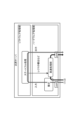
- FIG. 1 is a block diagram showing an example of the configuration of a communication device.
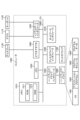
- FIG. 2 is a diagram illustrating processing by the communication device.
- FIG. 3 is a diagram illustrating processing by the communication device.
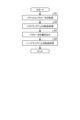
- FIG. 4 is a flowchart illustrating an example of the processing flow of the communication device.
- FIG. 5 is a block diagram showing an example of the configuration of a communication device.
- FIG. 6 is a diagram illustrating processing by the communication device.
- FIG. 7 is a flowchart illustrating an example of the processing flow of the communication device.
- FIG. 8 is a diagram showing an example of a computer that executes a communication program.
- the communication device 100 includes a communication section 110, a control section 120, and a storage section 130. Note that each of these units may be held in a distributed manner by a plurality of devices. The processing of each of these parts will be explained below.
- the communication unit 110 is realized by a NIC (Network Interface Card) or the like, and enables communication between an external device and the control unit 120 via a telecommunication line such as a LAN (Local Area Network) or the Internet.
- a NIC Network Interface Card
- LAN Local Area Network
- the communication unit 110 enables communication between an external device and the control unit 120.
- the storage unit 130 is realized by a semiconductor memory element such as a RAM (Random Access Memory) or a flash memory, or a storage device such as a hard disk or an optical disk.
- the information stored in the storage unit 130 includes, for example, a header hash value, a payload hash value, a function calculation method, and other information necessary for packet processing. Note that the information stored in the storage unit 130 is not limited to what is described above.
- the control unit 120 is realized using a CPU (Central Processing Unit), an NP (Network Processor), an FPGA (Field Programmable Gate Array), etc., and executes a processing program stored in a memory. As shown in FIG. 1, the control unit 120 includes an acquisition unit 121, a first processing unit 122, a calculation unit 123, a writing unit 124, and a second processing unit 125. Each section included in the control section 120 will be described below.
- the acquisition unit 121 acquires the packet. For example, the acquisition unit 121 acquires packets that require stateful processing. For example, the acquisition unit 121 acquires a packet to be subjected to NAPT (Network Address Port Translation).
- NAPT Network Address Port Translation
- the first processing unit 122 transfers the packet acquired by the acquisition unit 121 using software. For example, the first processing unit 122 performs a transfer process using the result of a bit operation. Further, for example, the first processing unit 122 performs a transfer process on the packet acquired by the acquisition unit 121 using software, using a processing result obtained by combining logical operations and bit operations such as bit shift and rotation.
- the calculation unit 123 calculates a function based on the packet acquired by the acquisition unit 121 and the packet transferred by the first processing unit 122. For example, the calculation unit 123 calculates a function from the difference between the bit strings of the packet acquired by the acquisition unit 121 and the packet subjected to bit arithmetic processing by the first processing unit 122. For example, the calculation unit 123 calculates the inverse function of the process from the difference in the bit strings of the packet acquired by the acquisition unit 121 and the packet subjected to bit operation processing by the first processing unit 122. Further, for example, in the case of NAPT, the calculation unit 123 can calculate a conversion pattern by acquiring a specific part of a packet header when converting an address to a port.
- the calculation unit 123 calculates a function from the difference between the bit strings of the packet before and after the GRE (Generic Routing Encapsulation) decapsulation process is performed by the first processing unit 122.
- GRE Generic Routing Encapsulation
- NAPT and GRE are given as examples, the calculation unit 123 can calculate functions even if it is a process that combines multiple processes in a complex manner, such as service function chaining, if it can obtain the difference between bit strings. It is possible.
- the second processing unit 125 inputs the packet acquired by the acquisition unit 121 to the function calculated by the calculation unit 123, and performs a transfer process by hardware using the output of the function. For example, the second processing unit 125 inputs the packet acquired by the acquisition unit 121 to the inverse function calculated by the calculation unit 123, and uses the output of the inverse function to perform transfer processing by hardware.
- processing by the communication device 100 will be described using FIG. 2.
- the acquisition unit 121 acquires a packet.
- the first processing unit 122 performs a transfer process using software.
- the communication device 100 performs the initial transfer process using software. Note that in FIG. 2, processing A and processing B correspond to the first processing section 122.
- the calculation unit 123 uses hardware to calculate a function based on the packet acquired by the acquisition unit 121 and the packet transferred by the first processing unit 122.
- the inverse function derivation section corresponds to the calculation section 123.
- the second processing unit 125 inputs the packet acquired by the acquisition unit 121 to the function calculated by the calculation unit 123, and performs a transfer process by hardware by using the output of the function. That is, after calculating the function, the communication device 100 performs processing using hardware. Note that in FIG. 2, the processing section corresponds to the second processing section 125.
- the communication device 100 speeds up the determination of whether the flows are the same by calculating the hash value of the header. Furthermore, the communication device 100 checks whether the input packet to the host processing unit and the output packet are the same by using the hash value of the payload calculated by the payload hash calculation unit. Note that the communication device 100 may check whether the input packet to the host processing unit and the output packet are the same by marking the packets.
- the inverse function calculation unit that calculates the function of the communication device 100 derives an inverse function by using bit operators for addition operation, multiplication operation, and bit shift parameters.
- the communication device 100 may save flow entries by setting a survival time for each flow and erasing flows with no longer communication as needed.
- the communication device 100 can perform high-speed lookups and function calculations.
- steps S11 to S14 described below can also be executed in a different order. Also, some of the steps S11 to S14 described below may be omitted.
- the acquisition unit 121 acquires a packet (step S11). For example, the acquisition unit 121 acquires packets that require stateful processing such as NAPT.
- the first processing unit 122 transfers the packet acquired by the acquisition unit 121 using software (step S12).
- the first processing unit 122 transfers the packet acquired by the acquisition unit 121 using software using a processing result that is a combination of logical operations and bit operations such as bit shift and rotation.
- the calculation unit 123 calculates a function based on the packet acquired by the acquisition unit 121 and the packet transferred by the first processing unit 122 (step S13). For example, the calculation unit 123 calculates a function from the difference in bit strings between the packet acquired by the acquisition unit 121 and the packet subjected to bit arithmetic processing by the first processing unit 122.
- the second processing unit 125 inputs the packet acquired by the acquisition unit 121 to the function calculated by the calculation unit 123, and performs a transfer process by hardware using the output of the function (step S14).
- the communication device 100 includes an acquisition section 121, a first processing section 122, a calculation section 123, and a second processing section 125.
- the acquisition unit 121 acquires packets.
- the first processing unit 122 transfers the packet acquired by the acquisition unit 121 using software.
- the calculation unit 123 uses hardware to calculate a function based on the packet acquired by the acquisition unit 121 and the packet transferred by the first processing unit 122.
- the second processing unit 125 inputs the packet acquired by the acquisition unit 121 to the function calculated by the calculation unit 123, and performs a transfer process by hardware using the output of the function.
- the first processing unit 122 performs a transfer process using bit operations
- the calculation unit 123 uses the packet acquired by the acquisition unit 121 and the first processing unit 122 to perform a transfer process.
- the function is calculated from the difference in the bit string from the received packet.
- the communication device 100 can perform autonomous calculation by hardware for processing that can obtain differences between bit strings, and can perform stateful packet processing at high speed without increasing the implementation scale.
- the communication device 100 can change the calculation unit 123 or the second processing unit 125 as long as the change allows bit operation processing. Processing can be performed without any That is, even when the software processing section shown in FIG. 2 includes processing A and processing B, processing C, processing D, and processing E, the same circuit can be used as the hardware processing section.
- rules for packet transfer processing performed by software are set in hardware as parameters, thereby enabling high-speed packet transfer processing by hardware.
- the communication device 100 includes a communication section 110, a control section 120, and a storage section 130. Note that each of these units may be held in a distributed manner by a plurality of devices.
- the storage unit 130 stores, for example, a routing table and other information necessary for processing packets. Note that the information stored in the storage unit 130 is not limited to what is described above.
- control unit 120 includes an acquisition unit 121, a first processing unit 122, a writing unit 124, and a second processing unit 125. Each section included in the control section 120 will be described below.
- the acquisition unit 121 acquires the packet and predetermined parameters. For example, the acquisition unit 121 acquires a packet that requires stateful processing and parameters necessary for stateful processing. More specifically, in the case of NAPT, the acquisition unit 121 acquires the packet to be subjected to NAPT and the parameters of the address/port conversion table. Note that the target of the packets and predetermined parameters that the acquisition unit 121 acquires is not limited to NAPT, but it is necessary to perform table-based processing such as stateful firewall, ARP (Address Resolution Protocol), routing, policy-based routing, etc. This includes all processes that need to have a state such as processing or session information.
- table-based processing such as stateful firewall, ARP (Address Resolution Protocol), routing, policy-based routing, etc. This includes all processes that need to have a state such as processing or session information.
- the first processing unit 122 uses software to transfer the packets acquired by the acquisition unit 121 based on predetermined parameters acquired by the acquisition unit 121. For example, the first processing unit 122 performs a process of converting the address and port of a packet to be subjected to NAPT by using the parameters of the address and port conversion table.
- the writing unit 124 writes the predetermined parameters used in the transfer process by the first processing unit 122 into the hardware.
- the writing unit 124 writes the parameters of the routing table to hardware such as rewriting a circuit of an FPGA that can be operated from software, writing to a register value, and writing to RAM.
- the second processing unit 125 transfers the packet acquired by the acquisition unit 121 using hardware based on the predetermined parameters written by the writing unit 124. For example, the second processing unit 125 transfers the packet subject to NAPT based on the routing table.
- the transfer process by the communication device 100 will be explained using FIG. 6.
- the acquisition unit 121 acquires a packet and parameters.
- the first processing unit 122 uses software to transfer the packet acquired by the acquisition unit 121 based on the predetermined parameters acquired by the acquisition unit 121.
- the communication device 100 performs the initial transfer process using software. Note that in FIG. 6, stateful processing corresponds to the first processing unit 122.
- the writing unit 124 writes the predetermined parameters used in the transfer process by the first processing unit 122 into the hardware.
- the writing unit 124 writes predetermined parameters into a register. That is, the communication device 100 sets packet processing rules in hardware.
- the second processing unit 125 transfers the packet acquired by the acquisition unit 121 using hardware based on the predetermined parameters written by the writing unit 124. That is, after calculating the function, the communication device 100 performs a transfer process using hardware. Note that in FIG. 6, the high-speed processing section corresponds to the second processing section 125. [flowchart]
- steps S21 to S24 described below can also be executed in a different order. Furthermore, some of the steps S21 to S24 described below may be omitted.
- the acquisition unit 121 acquires a packet and parameters (step S21). For example, the acquisition unit 121 acquires a packet to be subjected to NAPT and a routing table.
- the first processing unit 122 uses software to transfer the packet acquired by the acquisition unit 121 based on the predetermined parameters acquired by the acquisition unit 121 (step S22). For example, the first processing unit 122 performs a process of converting the address and port of a packet to be subjected to NAPT by using the parameters of the address and port conversion table.
- the writing unit 124 writes into the hardware the predetermined parameters used in the transfer process by the first processing unit 122 (step S23).
- the writing unit 124 writes the parameters of the routing table to hardware such as rewriting a circuit of an FPGA that can be operated from software, writing to a register value, and writing to RAM.
- the second processing unit 125 transfers the packet acquired by the acquisition unit 121 using hardware based on the predetermined parameters written by the writing unit 124 (step S24). For example, the second processing unit 125 transfers the packet subject to NAPT based on the routing table.
- the communication device 100 includes an acquisition section 121, a first processing section 122, a writing section 124, and a second processing section 125.
- the acquisition unit 121 acquires the packet and predetermined parameters.
- the first processing unit 122 uses software to transfer the packet acquired by the acquisition unit 121 based on the predetermined parameters acquired by the acquisition unit 121.
- the writing unit 124 writes predetermined parameters used in the transfer process by the first processing unit 122 into hardware.
- the second processing unit 125 uses hardware to transfer the packet acquired by the acquisition unit 121 based on predetermined parameters written by the writing unit 124.
- the communication device 100 can set a packet processing pattern processed by software in hardware, and perform stateful packet processing at high speed without increasing the implementation scale.
- the first processing unit 122 in the communication device 100 performs a transfer process based on a routing table as a predetermined parameter, and the writing unit 124 writes information of the routing table to the hardware, and the writing unit 124 writes the information of the routing table to the hardware. performs forwarding processing based on the routing table.
- the communication device 100 can set a packet processing pattern in hardware based on a routing table processed by software, and can perform stateful packet processing at high speed without increasing the implementation scale.
- program Further, it is also possible to create a program in which the processing executed by the communication device 100 described in the above embodiment is written in a computer-executable language. In this case, when the computer executes the program, the same effects as in the above embodiment can be obtained. Furthermore, the same processing as in the above embodiments may be realized by recording such a program on a computer-readable recording medium and having the computer read and execute the program recorded on this recording medium.
- FIG. 8 is a diagram showing a computer that executes the program.
- the computer 1000 includes, for example, a memory 1010, a CPU 1020, a hard disk drive interface 1030, a disk drive interface 1040, a serial port interface 1050, a video adapter 1060, and a network interface 1070. However, each of these parts is connected by a bus 1080.
- the memory 1010 includes a ROM (Read Only Memory) 1011 and a RAM 1012, as illustrated in FIG.
- the ROM 1011 stores, for example, a boot program such as BIOS (Basic Input Output System).
- BIOS Basic Input Output System
- Hard disk drive interface 1030 is connected to hard disk drive 1090, as illustrated in FIG.
- the disk drive interface 1040 is connected to the disk drive 1100, as illustrated in FIG.
- a removable storage medium such as a magnetic disk or an optical disk is inserted into disk drive 1100.
- the serial port interface 1050 is connected to, for example, a mouse 1110 and a keyboard 1120, as illustrated in FIG.
- Video adapter 1060 is connected to display 1130, for example, as illustrated in FIG.
- the hard disk drive 1090 stores, for example, an OS 1091, an application program 1092, a program module 1093, and program data 1094. That is, the above program is stored, for example, in the hard disk drive 1090 as a program module in which commands to be executed by the computer 1000 are written.
- the various data described in the above embodiments are stored as program data in, for example, the memory 1010 or the hard disk drive 1090.
- the CPU 1020 reads out the program module 1093 and program data 1094 stored in the memory 1010 and the hard disk drive 1090 to the RAM 1012 as necessary, and executes various processing procedures.
- program module 1093 and program data 1094 related to the program are not limited to being stored in the hard disk drive 1090, and may be stored in a removable storage medium, for example, and read by the CPU 1020 via a disk drive or the like. .
- the program module 1093 and program data 1094 related to the program are stored in another computer connected via a network (LAN (Local Area Network), WAN (Wide Area Network), etc.), and are transmitted via the network interface 1070. It may be read by the CPU 1020.
- LAN Local Area Network
- WAN Wide Area Network
- module, -er suffix, -or suffix can be read as unit, means, circuit, etc.
- a communication module, a control module, and a storage module can be read as a communication unit, a control unit, and a storage unit, respectively.
- communication device 110 communication unit 120 control unit 121 acquisition unit 122 first processing unit 123 calculation unit 124 writing unit 125 second processing unit 130 storage unit
Landscapes
- Engineering & Computer Science (AREA)
- Computer Networks & Wireless Communication (AREA)
- Signal Processing (AREA)
- Data Exchanges In Wide-Area Networks (AREA)
Abstract
本発明の通信装置(100)は、パケットを取得する取得部(121)と、取得部(121)により取得されたパケットを、ソフトウェアにより転送処理を行う第一の処理部(122)と、取得部(121)により取得されたパケットと第一の処理部(122)により転送処理が行われたパケットとに基づいてハードウェアにより関数を計算する計算部(123)と、取得部(121)により取得されたパケットを、計算部(123)により計算された関数に入力し、関数による出力を用いて、ハードウェアにより転送処理を行う第二の処理部(125)とを有する。
Description
本発明は、通信装置、通信方法および通信プログラムに関する。
従来、パケット処理の実装には、CPUなどを利用しソフトウェアで実装するパケット処理方法と、ASICやNPU、FPGAなどのハードウェアを利用して実装したパケット処理方法が存在する。また、ステートフルなパケット処理はハードウェアでの実装が困難なため、ソフトウェアでの柔軟な実装が行われる。
Behavior of NAPT Middleware in an SDN Environment DOI: 10.1109/EICT48899.2019.9068752
しかしながら、従来技術では、実装規模を増大させることなく、ステートフルなパケット処理を高速に行うことができないという課題がある。例えば、ソフトウェア処理では柔軟な実装が可能であるが、処理スピードが低いという欠点がある。また、例えば、NAPTなどステートを持つようなパケット処理では、パケットフローごとに複雑な処理が必要であるため、ASICやFPGAなどによるハードウェア処理を行うのは困難である。
ハードウェア処理は単純な処理を高速で行うことができるが、ステートフルな処理に対応させると実装規模が増大してしまうためである。
本発明は、上記に鑑みてなされたものであって、ステートフルなパケット処理を高速に行う通信装置、通信方法および通信プログラムを提供することを目的とする。
上述した課題を解決し、目的を達成するために、本発明の通信装置は、パケットを取得する取得部と、取得部により取得されたパケットを、ソフトウェアにより転送処理を行う第一の処理部と、取得部により取得されたパケットと第一の処理部により転送処理が行われたパケットとに基づいてハードウェアにより関数を計算する計算部と、取得部により取得されたパケットを、計算部により計算された関数に入力し、関数による出力を用いて、ハードウェアにより転送処理を行う第二の処理部とを有する。
本発明によれば、実装規模を増大させることなく、ステートフルなパケット処理を高速に行うことができる。
以下、図面を参照して、本願に係る通信装置、通信方法および通信プログラムの実施形態を詳細に説明する。なお、この実施の形態により本発明が限定されるものではない。また、図面の記載において、同一部分には同一の符号を付して示しており、重複する説明は省略される。
[実施形態1]
[通信装置の構成]
次に、図1を用いて、通信装置100の構成について説明する。図1が示すように、通信装置100は、通信部110と、制御部120と、記憶部130とを有する。なお、これらの各部は、複数の装置が分散して保持してもよい。以下にこれら各部の処理を説明する。
[通信装置の構成]
次に、図1を用いて、通信装置100の構成について説明する。図1が示すように、通信装置100は、通信部110と、制御部120と、記憶部130とを有する。なお、これらの各部は、複数の装置が分散して保持してもよい。以下にこれら各部の処理を説明する。
通信部110は、NIC(Network Interface Card)等で実現され、LAN(Local Area Network)やインターネットなどの電気通信回線を介した外部装置と制御部120の通信を可能とする。例えば、通信部110は、外部装置と制御部120との通信を可能とする。
記憶部130は、RAM(Random Access Memory)、フラッシュメモリ(Flash Memory)等の半導体メモリ素子、または、ハードディスク、光ディスク等の記憶装置によって実現される。記憶部130が記憶する情報としては、例えば、ヘッダハッシュ値、ペイロードハッシュ値、関数の計算方法、その他パケットの処理に必要な情報などが含まれる。なお、記憶部130が記憶する情報は上記に記載したものに限定されない。
制御部120は、CPU(Central Processing Unit)やNP(Network Processor)やFPGA(Field Programmable Gate Array)等を用いて実現され、メモリに記憶された処理プログラムを実行する。図1に示すように、制御部120は、取得部121と、第一の処理部122と、計算部123と、書き込み部124と、第二の処理部125とを有する。以下、制御部120が有する各部について説明する。
取得部121は、パケットを取得する。例えば、取得部121は、ステートフルな処理が必要となるパケットを取得する。例えば、取得部121は、NAPT(Network Address Port Translation)の対象となるパケットを取得する。
第一の処理部122は、取得部121により取得されたパケットを、ソフトウェアにより転送処理する。例えば、第一の処理部122は、ビット演算による演算結果を用いて転送処理を行う。また、例えば、第一の処理部122は、取得部121により取得されたパケットを、論理演算やビットシフト、ローテートなどのビット演算を組み合わせた処理結果を用いて、ソフトウェアにより転送処理を行う。
計算部123は、取得部121により取得されたパケットと第一の処理部122により転送処理が行われたパケットとに基づいて、関数を計算する。例えば、計算部123は、取得部121により取得されたパケットと第一の処理部122によりビット演算処理されたパケットとのパケットのビット列の差分から、関数を計算する。例えば、計算部123は、取得部121により取得されたパケットと第一の処理部122によりビット演算処理されたパケットとのパケットのビット列の差分から、処理の逆関数を計算する。また、例えば、計算部123は、NAPTの場合、アドレスポート変換に際して、パケットヘッダの特定箇所を取得することで変換パターンを計算することが可能である。
また、例えば、計算部123は、第一の処理部122により、GRE(Generic Routing Encapsulation)デカプセルの処理が行われる前後のパケットのビット列の差分から、関数を計算する。また、例としてNAPTやGREを挙げたが、計算部123は、サービスファンクションチェイニングなど、複数の処理を複雑に組み合わせた処理であっても、ビット列の差分を得ることができれば、関数の計算が可能である。
第二の処理部125は、取得部121により取得されたパケットを、計算部123により計算された関数に入力し、関数による出力を用いて、ハードウェアにより転送処理する。例えば、第二の処理部125は、取得部121により取得されたパケットを、計算部123により計算された逆関数に入力し、逆関数による出力を用いて、ハードウェアにより転送処理する。
[通信装置による処理]
次に、図2を用いて、通信装置100による処理について説明する。まず、取得部121はパケットを取得する。次に、第一の処理部122は、ソフトウェアにより転送処理を行う。つまり、通信装置100は、最初の転送処理についてはソフトウェアで行う。なお、図2においては、処理Aと処理Bとが第一の処理部122に該当する。
次に、図2を用いて、通信装置100による処理について説明する。まず、取得部121はパケットを取得する。次に、第一の処理部122は、ソフトウェアにより転送処理を行う。つまり、通信装置100は、最初の転送処理についてはソフトウェアで行う。なお、図2においては、処理Aと処理Bとが第一の処理部122に該当する。
それから、計算部123は、取得部121により取得されたパケットと、第一の処理部122により転送処理が行われたパケットとに基づいてハードウェアにより関数を計算する。図2においては、逆関数導出部が計算部123に該当する。
そして、第二の処理部125は、取得部121により取得されたパケットを、計算部123により計算された関数に入力し、当該関数による出力を用いることで、ハードウェアによる転送処理を行う。つまり、通信装置100は、関数の計算後は、ハードウェアにより処理を行う。なお、図2においては、処理部が第二の処理部125に該当する。
次に、図3を用いて、通信装置100による処理について詳細に説明する。通信装置100は、同一フローか否かの判定について、ヘッダのハッシュ値を計算することで高速化する。また、通信装置100は、ホスト処理部への入力パケットと出力パケットが同一か否かの突合せを、ペイロードハッシュ計算部により計算されるペイロードのハッシュ値を用いることで実現する。なお、通信装置100は、パケットへのマーキングによって、ホスト処理部への入力パケットと出力パケットが同一か否かの突合せを行ってもよい。
また、通信装置100の関数の計算を行う逆関数計算部は、加算演算・乗算演算・ビットシフトのパラメータを、ビット演算子を用いることにより逆関数を導出する。通信装置100は、各フローについて生存時間を設け、通信がなくなったフローについては随時消去することにより、フローエントリの節約を行ってもよい。
通信装置100は、上述の処理を行うことにより、高速なルックアップ、関数計算を行うことができる。
[フローチャート]
次に、図4を用いて、通信装置100による処理の流れについて説明する。なお、下記のステップS11~S14は、異なる順序で実行することもできる。また、下記のステップS11~S14のうち、省略される処理があってもよい。
次に、図4を用いて、通信装置100による処理の流れについて説明する。なお、下記のステップS11~S14は、異なる順序で実行することもできる。また、下記のステップS11~S14のうち、省略される処理があってもよい。
まず、取得部121は、パケットを取得する(ステップS11)。例えば、取得部121は、NAPTのようなステートフルな処理が必要となるパケットを取得する。
次に、第一の処理部122は、取得部121により取得されたパケットを、ソフトウェアにより転送処理する(ステップS12)。例えば、第一の処理部122は、取得部121により取得されたパケットを、論理演算やビットシフト、ローテートなどのビット演算を組み合わせた処理結果を用いて、ソフトウェアにより転送処理する。
それから、計算部123は、取得部121により取得されたパケットと第一の処理部122により転送処理されたパケットとに基づいて、関数を計算する(ステップS13)。例えば、計算部123は、取得部121により取得されたパケットと第一の処理部122によりビット演算処理されたパケットとのビット列の差分から、関数を計算する。
そして、第二の処理部125は、取得部121により取得されたパケットを、計算部123により計算された関数に入力し、関数による出力を用いて、ハードウェアにより転送処理する(ステップS14)。
[効果]
実施形態に係る通信装置100は、取得部121と、第一の処理部122と、計算部123と、第二の処理部125とを有する。取得部121は、パケットを取得する。第一の処理部122は、取得部121により取得されたパケットを、ソフトウェアにより転送処理する。計算部123は、取得部121により取得されたパケットと第一の処理部122により転送処理が行われたパケットとに基づいてハードウェアにより関数を計算する。第二の処理部125は、取得部121により取得されたパケットを、計算部123により計算された関数に入力し、当該関数による出力を用いて、ハードウェアにより転送処理する。
実施形態に係る通信装置100は、取得部121と、第一の処理部122と、計算部123と、第二の処理部125とを有する。取得部121は、パケットを取得する。第一の処理部122は、取得部121により取得されたパケットを、ソフトウェアにより転送処理する。計算部123は、取得部121により取得されたパケットと第一の処理部122により転送処理が行われたパケットとに基づいてハードウェアにより関数を計算する。第二の処理部125は、取得部121により取得されたパケットを、計算部123により計算された関数に入力し、当該関数による出力を用いて、ハードウェアにより転送処理する。
これにより通信装置100は、ハードウェアでパケット処理パターンを自律的に計算し、実装規模を増大させることなく、ステートフルなパケット処理を高速に行うことができる。
また、通信装置100において、第一の処理部122は、ビット演算によって転送処理を行い、計算部123は、取得部121により取得されたパケットと、第一の処理部122により転送処理が行われたパケットとのビット列の差分から関数を計算する。これにより通信装置100は、ビット列の差分を得ることができる処理について、ハードウェアによる自律的な計算を可能とし、実装規模を増大させることなく、ステートフルなパケット処理を高速に行うことができる。
また、これにより、通信装置100は、第一の処理部122における処理が複雑化、多段化した場合でも、ビット演算処理可能な変更であれば、計算部123や第二の処理部125の変更を伴うことなく処理を行うことができる。すなわち、図2に示すソフトウェア処理部の処理A、処理Bに加え、処理C、処理D、処理Eと増えた場合においても、ハードウェア処理部は同じ回路を使うことができる。
[実施形態2]
次に実施形態2について説明する。上述の実施形態1と共通する部分については、説明を適宜省略する。上述の実施形態1では、ソフトウェアで行われるパケット転送処理の入出力から関数を計算し、関数を用いることでハードウェアによる高速なパケット転送処理を可能とする。
次に実施形態2について説明する。上述の実施形態1と共通する部分については、説明を適宜省略する。上述の実施形態1では、ソフトウェアで行われるパケット転送処理の入出力から関数を計算し、関数を用いることでハードウェアによる高速なパケット転送処理を可能とする。
これに対して、実施形態2では、ソフトウェアで行われるパケット転送処理のルールをパラメータとしてハードウェアに設定することでハードウェアによる高速なパケット転送処理を可能とする。
[通信装置の構成]
次に、図5を用いて、通信装置100の構成について説明する。図5が示すように、通信装置100は、通信部110と、制御部120と、記憶部130とを有する。なお、これらの各部は、複数の装置が分散して保持してもよい。
次に、図5を用いて、通信装置100の構成について説明する。図5が示すように、通信装置100は、通信部110と、制御部120と、記憶部130とを有する。なお、これらの各部は、複数の装置が分散して保持してもよい。
記憶部130は、例えば、ルーティングテーブル、その他パケットの処理に必要な情報を記憶する。なお、記憶部130が記憶する情報は上記に記載したものに限定されない。
図5に示すように、制御部120は、取得部121と、第一の処理部122と、書き込み部124と、第二の処理部125とを有する。以下、制御部120が有する各部について説明する。
取得部121は、パケットと所定のパラメータとを取得する。例えば、取得部121は、ステートフルな処理が必要となるパケットと、ステートフルな処理に必要なパラメータを取得する。より具体的には、取得部121は、NAPTの場合、NAPTの対象となるパケットと、アドレスポート変換テーブルのパラメータとを取得する。なお、取得部121が取得するパケットと所定のパラメータとの対象はNAPTに限定されず、ステートフルファイアウォール、ARP(Address Resolution Protocol)、ルーティング、ポリシーベースルーティングなど、テーブルに基づいた処理を行う必要がある処理、またはセッション情報などのステートを持つ必要がある処理全般が含まれるものとする。
第一の処理部122は、取得部121により取得されたパケットを、取得部121により取得された所定のパラメータに基づいて、ソフトウェアにより転送処理を行う。例えば、第一の処理部122は、NAPTの対象となるパケットを、アドレスポート変換テーブルのパラメータを用いることにより、アドレスポート変換する処理を行う。
書き込み部124は、第一の処理部122による転送処理に用いられた所定のパラメータをハードウェアに書き込む。例えば、書き込み部124は、ルーティングテーブルのパラメータを、ソフトウェアから操作可能なFPGAの回路書き換えや、レジスタ値への書き込み、RAMへの書き込みなどのようにハードウェアに書き込む。
第二の処理部125は、取得部121により取得されたパケットを、書き込み部124により書き込まれた所定のパラメータに基づいて、ハードウェアにより転送処理する。例えば、第二の処理部125は、NAPTの対象となるパケットを、ルーティングテーブルに基づいて、転送処理する。
[転送処理]
次に、図6を用いて、通信装置100による転送処理について説明する。まず、取得部121は、パケットとパラメータとを取得する。次に、第一の処理部122は、取得部121により取得されたパケットを、取得部121により取得された所定のパラメータに基づいて、ソフトウェアにより転送処理を行う。つまり、通信装置100は、最初の転送処理についてはソフトウェアで行う。なお、図6において、ステートフル処理が第一の処理部122に該当する。
次に、図6を用いて、通信装置100による転送処理について説明する。まず、取得部121は、パケットとパラメータとを取得する。次に、第一の処理部122は、取得部121により取得されたパケットを、取得部121により取得された所定のパラメータに基づいて、ソフトウェアにより転送処理を行う。つまり、通信装置100は、最初の転送処理についてはソフトウェアで行う。なお、図6において、ステートフル処理が第一の処理部122に該当する。
それから、書き込み部124は、第一の処理部122による転送処理に用いられた所定のパラメータをハードウェアに書き込む。例えば、書き込み部124は、レジスタに所定のパラメータを書き込む。つまり、通信装置100は、パケット処理ルールをハードウェアに設定する。
そして、第二の処理部125は、取得部121により取得されたパケットを、書き込み部124により書き込まれた所定のパラメータに基づいて、ハードウェアにより転送処理する。つまり、通信装置100は、関数の計算後は、ハードウェアにより転送処理を行う。なお、図6においては、高速処理部が第二の処理部125に該当する。
[フローチャート]
[フローチャート]
次に、図7を用いて、通信装置100による処理の流れについて説明する。なお、下記のステップS21~S24は、異なる順序で実行することもできる。また、下記のステップS21~S24のうち、省略される処理があってもよい。
まず、取得部121は、パケットとパラメータとを取得する(ステップS21)。例えば、取得部121は、NAPTの対象となるパケットと、ルーティングテーブルとを取得する。
次に、第一の処理部122は、取得部121により取得されたパケットを、取得部121により取得された所定のパラメータに基づいて、ソフトウェアにより転送処理を行う(ステップS22)。例えば、第一の処理部122は、NAPTの対象となるパケットを、アドレスポート変換テーブルのパラメータを用いることにより、アドレスポート変換する処理を行う。
それから、書き込み部124は、第一の処理部122による転送処理に用いられた所定のパラメータをハードウェアに書き込む(ステップS23)。例えば、書き込み部124は、ルーティングテーブルのパラメータを、ソフトウェアから操作可能なFPGAの回路書き換えや、レジスタ値への書き込み、RAMへの書き込みなどのようにハードウェアに書き込む。
そして、第二の処理部125は、取得部121により取得されたパケットを、書き込み部124により書き込まれた所定のパラメータに基づいて、ハードウェアにより転送処理する(ステップS24)。例えば、第二の処理部125は、NAPTの対象となるパケットを、ルーティングテーブルに基づいて、転送処理する。
[効果]
実施形態に係る通信装置100は、取得部121と、第一の処理部122と、書き込み部124と、第二の処理部125とを有する。取得部121は、パケットと所定のパラメータとを取得する。第一の処理部122は、取得部121により取得されたパケットを、取得部121により取得された所定のパラメータに基づいて、ソフトウェアにより転送処理する。書き込み部124は、第一の処理部122による転送処理に用いられた所定のパラメータをハードウェアに書き込む。第二の処理部125は、取得部121により取得されたパケットを、書き込み部124により書き込まれた所定のパラメータに基づいて、ハードウェアにより転送処理する。
実施形態に係る通信装置100は、取得部121と、第一の処理部122と、書き込み部124と、第二の処理部125とを有する。取得部121は、パケットと所定のパラメータとを取得する。第一の処理部122は、取得部121により取得されたパケットを、取得部121により取得された所定のパラメータに基づいて、ソフトウェアにより転送処理する。書き込み部124は、第一の処理部122による転送処理に用いられた所定のパラメータをハードウェアに書き込む。第二の処理部125は、取得部121により取得されたパケットを、書き込み部124により書き込まれた所定のパラメータに基づいて、ハードウェアにより転送処理する。
これにより通信装置100は、ソフトウェアで処理されるパケット処理パターンをハードウェアに設定し、実装規模を増大させることなく、ステートフルなパケット処理を高速に行うことができる。
また、通信装置100における第一の処理部122は、所定のパラメータとしてルーティングテーブルに基づいて転送処理を行い、書き込み部124は、ルーティングテーブルの情報を前記ハードウェアに書き込み、第二の処理部125は、ルーティングテーブルに基づいて転送処理を行う。これにより通信装置100は、ソフトウェアで処理されるルーティングテーブルに基づいたパケット処理パターンをハードウェアに設定し、実装規模を増大させることなく、ステートフルなパケット処理を高速に行うことができる。
[プログラム]
また、上記実施形態において説明した通信装置100が実行する処理をコンピュータが実行可能な言語で記述したプログラムを作成することもできる。この場合、コンピュータがプログラムを実行することにより、上記実施形態と同様の効果を得ることができる。さらに、かかるプログラムをコンピュータ読み取り可能な記録媒体に記録して、この記録媒体に記録されたプログラムをコンピュータに読み込ませて実行することにより上記実施形態と同様の処理を実現してもよい。
また、上記実施形態において説明した通信装置100が実行する処理をコンピュータが実行可能な言語で記述したプログラムを作成することもできる。この場合、コンピュータがプログラムを実行することにより、上記実施形態と同様の効果を得ることができる。さらに、かかるプログラムをコンピュータ読み取り可能な記録媒体に記録して、この記録媒体に記録されたプログラムをコンピュータに読み込ませて実行することにより上記実施形態と同様の処理を実現してもよい。
図8は、プログラムを実行するコンピュータを示す図である。図8に例示するように、コンピュータ1000は、例えば、メモリ1010と、CPU1020と、ハードディスクドライブインタフェース1030と、ディスクドライブインタフェース1040と、シリアルポートインタフェース1050と、ビデオアダプタ1060と、ネットワークインタフェース1070とを有し、これらの各部はバス1080によって接続される。
メモリ1010は、図8に例示するように、ROM(Read Only Memory)1011及びRAM1012を含む。ROM1011は、例えば、BIOS(Basic Input Output System)等のブートプログラムを記憶する。ハードディスクドライブインタフェース1030は、図8に例示するように、ハードディスクドライブ1090に接続される。
ディスクドライブインタフェース1040は、図8に例示するように、ディスクドライブ1100に接続される。例えば、磁気ディスクや光ディスク等の着脱可能な記憶媒体が、ディスクドライブ1100に挿入される。シリアルポートインタフェース1050は、図8に例示するように、例えば、マウス1110、キーボード1120に接続される。ビデオアダプタ1060は、図8に例示するように、例えばディスプレイ1130に接続される。
ここで、図8に例示するように、ハードディスクドライブ1090は、例えば、OS1091、アプリケーションプログラム1092、プログラムモジュール1093、プログラムデータ1094を記憶する。すなわち、上記のプログラムは、コンピュータ1000によって実行される指令が記述されたプログラムモジュールとして、例えば、ハードディスクドライブ1090に記憶される。
また、上記実施形態で説明した各種データは、プログラムデータとして、例えば、メモリ1010やハードディスクドライブ1090に記憶される。そして、CPU1020が、メモリ1010やハードディスクドライブ1090に記憶されたプログラムモジュール1093やプログラムデータ1094を必要に応じてRAM1012に読み出し、各種処理手順を実行する。
なお、プログラムに係るプログラムモジュール1093やプログラムデータ1094は、ハードディスクドライブ1090に記憶される場合に限られず、例えば着脱可能な記憶媒体に記憶され、ディスクドライブ等を介してCPU1020によって読み出されてもよい。あるいは、プログラムに係るプログラムモジュール1093やプログラムデータ1094は、ネットワーク(LAN(Local Area Network)、WAN(Wide Area Network)等)を介して接続された他のコンピュータに記憶され、ネットワークインタフェース1070を介してCPU1020によって読み出されてもよい。
[その他]
様々な実施形態を、図面を参照して、本明細書で詳細に説明したが、これらの複数の実施形態は例であり、本発明をこれらの複数の実施形態に限定することを意図するものではない。本明細書に記載された特徴は、当業者の知識に基づく様々な変形や改良を含む、様々な方法によって実現され得る。例えば、ソフトウェアにより行われる処理と、ハードウェアにより行われる処理とを、それぞれ異なる装置により行うことで実現してもよい。
様々な実施形態を、図面を参照して、本明細書で詳細に説明したが、これらの複数の実施形態は例であり、本発明をこれらの複数の実施形態に限定することを意図するものではない。本明細書に記載された特徴は、当業者の知識に基づく様々な変形や改良を含む、様々な方法によって実現され得る。例えば、ソフトウェアにより行われる処理と、ハードウェアにより行われる処理とを、それぞれ異なる装置により行うことで実現してもよい。
また、上述した「部(module、-er接尾辞、-or接尾辞)」は、ユニット、手段、回路などに読み替えることができる。例えば、通信部(communication module)、制御部(control module)および記憶部(storage module)は、それぞれ、通信ユニット、制御ユニットおよび記憶ユニットに読み替えることができる。
100 通信装置
110 通信部
120 制御部
121 取得部
122 第一の処理部
123 計算部
124 書き込み部
125 第二の処理部
130 記憶部
110 通信部
120 制御部
121 取得部
122 第一の処理部
123 計算部
124 書き込み部
125 第二の処理部
130 記憶部
Claims (7)
- パケットを取得する取得部と、
前記取得部により取得されたパケットを、ソフトウェアにより転送処理する第一の処理部と、
前記取得部により取得されたパケットと前記第一の処理部により転送処理が行われたパケットとに基づいてハードウェアにより関数を計算する計算部と、
前記取得部により取得されたパケットを、前記計算部により計算された関数に入力し、当該関数による出力を用いて、前記ハードウェアにより転送処理する第二の処理部と
を有することを特徴とする通信装置。 - 前記第一の処理部は、ビット演算によって転送処理を行い、
前記計算部は、前記取得部により取得されたパケットと、前記第一の処理部により転送処理が行われたパケットとのビット列の差分から関数を計算することを特徴とする請求項1に記載の通信装置。 - パケットと所定のパラメータとを取得する取得部と、
前記取得部により取得されたパケットを、前記取得部により取得された所定のパラメータに基づいて、ソフトウェアにより転送処理する第一の処理部と、
前記第一の処理部による転送処理に用いられた所定のパラメータをハードウェアに書き込む書き込み部と、
前記取得部により取得されたパケットを、前記書き込み部により書き込まれた所定のパラメータに基づいて、ハードウェアにより転送処理する第二の処理部と
を有することを特徴とする通信装置。 - 前記第一の処理部は、所定のパラメータとしてルーティングテーブルに基づいて転送処理を行い、
前記書き込み部は、前記ルーティングテーブルの情報を前記ハードウェアに書き込み、
前記第二の処理部は、前記ルーティングテーブルに基づいて転送処理を行うことを特徴とする請求項3に記載の通信装置。 - コンピュータが実施する通信方法であって、
パケットを取得する取得工程と、
前記取得工程により取得されたパケットを、ソフトウェアにより転送処理する第一の処理工程と、
前記取得工程により取得されたパケットと前記第一の処理工程により転送処理が行われたパケットとに基づいてハードウェアにより関数を計算する計算工程と、
前記取得工程により取得されたパケットを、前記計算工程により計算された関数に入力し、当該関数による出力を用いて、前記ハードウェアにより転送処理する第二の処理工程と
を含むことを特徴とする通信方法。 - コンピュータが実施する通信方法であって、
パケットと所定のパラメータとを取得する取得工程と、
前記取得工程により取得されたパケットを、前記取得工程により取得された所定のパラメータに基づいて、ソフトウェアにより転送処理する第一の処理工程と、
前記第一の処理工程による転送処理に用いられた所定のパラメータをハードウェアに書き込む書き込み工程と、
前記取得工程により取得されたパケットを、前記書き込み工程により書き込まれた所定のパラメータに基づいて、ハードウェアにより転送処理する第二の処理工程と
を含むことを特徴とする通信方法。 - コンピュータを、請求項1~4のうちいずれか1つに記載の通信装置として機能させるための通信プログラム。
Priority Applications (2)
| Application Number | Priority Date | Filing Date | Title |
|---|---|---|---|
| JP2024538804A JP7816530B2 (ja) | 2022-08-05 | 2022-08-05 | 通信装置、通信方法および通信プログラム |
| PCT/JP2022/030188 WO2024029092A1 (ja) | 2022-08-05 | 2022-08-05 | 通信装置、通信方法および通信プログラム |
Applications Claiming Priority (1)
| Application Number | Priority Date | Filing Date | Title |
|---|---|---|---|
| PCT/JP2022/030188 WO2024029092A1 (ja) | 2022-08-05 | 2022-08-05 | 通信装置、通信方法および通信プログラム |
Publications (1)
| Publication Number | Publication Date |
|---|---|
| WO2024029092A1 true WO2024029092A1 (ja) | 2024-02-08 |
Family
ID=89848990
Family Applications (1)
| Application Number | Title | Priority Date | Filing Date |
|---|---|---|---|
| PCT/JP2022/030188 Ceased WO2024029092A1 (ja) | 2022-08-05 | 2022-08-05 | 通信装置、通信方法および通信プログラム |
Country Status (2)
| Country | Link |
|---|---|
| JP (1) | JP7816530B2 (ja) |
| WO (1) | WO2024029092A1 (ja) |
Citations (2)
| Publication number | Priority date | Publication date | Assignee | Title |
|---|---|---|---|---|
| JPH1198143A (ja) * | 1997-09-17 | 1999-04-09 | Toshiba Corp | Atm中継装置 |
| JP2010109735A (ja) * | 2008-10-30 | 2010-05-13 | Iwatsu Electric Co Ltd | ルータ装置及びルーティング検索制御方法 |
Family Cites Families (1)
| Publication number | Priority date | Publication date | Assignee | Title |
|---|---|---|---|---|
| JP4676541B2 (ja) * | 2009-03-11 | 2011-04-27 | 株式会社日立製作所 | ネットワーク中継装置 |
-
2022
- 2022-08-05 WO PCT/JP2022/030188 patent/WO2024029092A1/ja not_active Ceased
- 2022-08-05 JP JP2024538804A patent/JP7816530B2/ja active Active
Patent Citations (2)
| Publication number | Priority date | Publication date | Assignee | Title |
|---|---|---|---|---|
| JPH1198143A (ja) * | 1997-09-17 | 1999-04-09 | Toshiba Corp | Atm中継装置 |
| JP2010109735A (ja) * | 2008-10-30 | 2010-05-13 | Iwatsu Electric Co Ltd | ルータ装置及びルーティング検索制御方法 |
Also Published As
| Publication number | Publication date |
|---|---|
| JPWO2024029092A1 (ja) | 2024-02-08 |
| JP7816530B2 (ja) | 2026-02-18 |
Similar Documents
| Publication | Publication Date | Title |
|---|---|---|
| CN108509210B (zh) | 自动更新基本输入输出系统的系统与方法 | |
| CN105453492B (zh) | 具有第三层分布式路由器功能的交换机集群 | |
| CN101455040B (zh) | 灵活且可扩展的接收端调节 | |
| CN106598560A (zh) | 基于iSCSI的操作系统映像部署及无磁盘启动的方法 | |
| EP3682603A1 (en) | Network traffic routing in distributed computing systems | |
| US11818096B2 (en) | Enforcement of inter-segment traffic policies by network fabric control plane | |
| US12355591B2 (en) | System for scaling network address translation (NAT) and firewall functions | |
| EP2846263A1 (en) | Methods for configurable hardware logic device reloading and devices thereof | |
| WO2012127886A1 (ja) | ネットワークシステム、及びポリシー経路設定方法 | |
| US20210226917A1 (en) | Lockless stateful network address translation | |
| CN109937400A (zh) | 用于虚拟机的实时迁移的流状态传送 | |
| US11533381B1 (en) | Method and system for transparent tcp proxy to containerized applications | |
| US20160205048A1 (en) | Supporting multiple vswitches on a single host | |
| US10616105B1 (en) | Extending virtual routing and forwarding using source identifiers | |
| WO2017028398A1 (zh) | 通信处理方法和装置 | |
| US10749842B2 (en) | Communication system and method for network address translation | |
| US9948568B2 (en) | Packet size control using maximum transmission units for facilitating packet transmission | |
| CN111800340B (zh) | 数据包转发方法和装置 | |
| US11025542B2 (en) | Routing packets in overlapping address spaces | |
| WO2024029092A1 (ja) | 通信装置、通信方法および通信プログラム | |
| US11146667B2 (en) | Configurable segmentation offload | |
| CN111526108B (zh) | 防止网络攻击的方法与装置 | |
| WO2022252634A1 (zh) | 数据流传输方法、装置、计算机设备及存储介质 | |
| CN116418747A (zh) | 一种数据传输系统、方法及装置 | |
| JP3750803B2 (ja) | パケットログ記録装置 |
Legal Events
| Date | Code | Title | Description |
|---|---|---|---|
| 121 | Ep: the epo has been informed by wipo that ep was designated in this application |
Ref document number: 22954080 Country of ref document: EP Kind code of ref document: A1 |
|
| WWE | Wipo information: entry into national phase |
Ref document number: 2024538804 Country of ref document: JP |
|
| NENP | Non-entry into the national phase |
Ref country code: DE |
|
| 122 | Ep: pct application non-entry in european phase |
Ref document number: 22954080 Country of ref document: EP Kind code of ref document: A1 |