WO2024024946A1 - 吻合補助具 - Google Patents
吻合補助具 Download PDFInfo
- Publication number
- WO2024024946A1 WO2024024946A1 PCT/JP2023/027771 JP2023027771W WO2024024946A1 WO 2024024946 A1 WO2024024946 A1 WO 2024024946A1 JP 2023027771 W JP2023027771 W JP 2023027771W WO 2024024946 A1 WO2024024946 A1 WO 2024024946A1
- Authority
- WO
- WIPO (PCT)
- Prior art keywords
- elongated member
- anastomosis
- guide member
- removal
- auxiliary guide
- Prior art date
- Legal status (The legal status is an assumption and is not a legal conclusion. Google has not performed a legal analysis and makes no representation as to the accuracy of the status listed.)
- Ceased
Links
Images


Classifications
-
- A—HUMAN NECESSITIES
- A61—MEDICAL OR VETERINARY SCIENCE; HYGIENE
- A61B—DIAGNOSIS; SURGERY; IDENTIFICATION
- A61B17/00—Surgical instruments, devices or methods
- A61B17/11—Surgical instruments, devices or methods for performing anastomosis; Buttons for anastomosis
Definitions
- the present invention relates to an anastomosis aid used for anastomosis of internal vessels such as blood vessels and lymphatic vessels through microscopic surgery.
- non-patent document 1 describes a ⁇ 2/0 nylon stent in which a 11/0 nylon stent is wrapped twice around the distal end and tied with a flat knot.'' There is.
- This auxiliary tool is used with a 2/0 nylon stent inserted into a microvessel from the anastomosis and an end of the 11/0 nylon stent taken out of the microvessel from the anastomosis.
- the cross sections of the anastomoses of the microvessels are brought together at the side periphery of the 2/0 nylon stent, and approximately 3/4 of the brought together anastomoses are adhered with a medical adhesive.
- the 2/0 nylon stent is taken out of the microvessel through the adhesive gap at the anastomosis.
- the above-mentioned anastomosis aid has a structure in which an 11/0 nylon stent is wound and tied around the end of a 2/0 nylon stent, and the 2/0 nylon stent is wrapped around the side of the 11/0 nylon stent. It will be in an extended state. For this reason, the pulling direction of the 11/0 nylon stent does not match the advancing direction of the tip of the 2/0 nylon stent, and when removing the 2/0 nylon stent from the microvessel, the 2/0 nylon stent must be It is necessary to finely adjust the pulling direction of the 11/0 nylon stent within a narrow range so that the tip of the stent does not get caught on the inner wall of the blood vessel.
- an object of the present invention is to provide an anastomosis aid that can be easily taken out from inside the canal after anastomosis.
- the present invention is an anastomosis aid comprising an elongated member to be inserted into a body canal and a removal assisting guide member extending from a distal end of the elongated member.
- an anastomosis aid that can be easily taken out from inside the canal after anastomosis.
- FIG. 1 is an overall view of the anastomosis aid according to the first embodiment. It is a figure showing the manufacturing process of the anastomosis aid concerning a 1st embodiment.
- FIG. 2 is a schematic diagram (part 1) for explaining an anastomosis procedure using the anastomosis aid according to the first embodiment.
- FIG. 2 is a schematic diagram (part 2) for explaining an anastomosis procedure using the anastomosis aid according to the first embodiment.
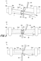
- FIG. 3 is an overall view of an anastomosis aid according to a second embodiment.
- FIG. 7 is an overall view of an anastomosis aid according to a third embodiment.
- FIG. 7 is an overall view of an anastomosis aid according to a fourth embodiment.
- each embodiment of the anastomosis aid of the present invention will be described in detail based on the drawings.
- the same components are given the same reference numerals, and overlapping explanations will be omitted.
- each embodiment of the present invention is not limited to each embodiment described below, and includes a long member inserted into a body canal and a distal end portion of the long member that has the effects of the present invention.
- the anastomosis aid may include all anastomosis aids having an extended extraction aid guide member.
- FIG. 1 is an overall view of an anastomosis aid 1 according to the first embodiment.
- An anastomosis aid 1 shown in FIG. 1 is used to prevent erroneous occlusion of a body canal during anastomosis of a body canal such as a blood vessel or lymphatic vessel by microscopic surgery.
- Such an anastomosis aid 1 includes an elongated member 10-1, a removal assisting guide member 20 fixed to the elongated member 10-1, and an adhesive 30.
- the elongated member 10-1 is used by being inserted into a body vessel such as a blood vessel or a lymphatic vessel.
- This elongated member 10-1 is hollow with at least one open end, and is cylindrical as shown, or has a cylindrical shape with one of both open ends closed. It is something that It is preferable that such an elongated member 10-1 is a member having a cylindrical outer diameter like that of a catheter, for example.
- the elongated member 10-1 is assumed to have enough rigidity to ensure the shape of the hollow portion. Further, the elongated member 10-1 preferably has flexibility to the extent that the hollow portion is crushed by an external force and the hollow portion is restored when the external force is removed, and is configured to be crushed and bent in the length direction. It is preferable that there be.
- the outer diameter [ ⁇ ] of the elongated member 10-1 is such that two elongated members 10-1 can be inserted into the elastic body canal with some margin, and It is set in various sizes depending on the size.
- the outer diameter [ ⁇ ] of the elongated member 10-1 is, for example, about 0.05 mm.
- the inner diameter and wall thickness of the elongated member 10-1 are not particularly limited, but should be large enough to ensure the elongated member 10-1 has flexibility while ensuring a hollow portion. do. Further, the elongated member 10-1 has an inner diameter large enough to allow insertion of a removal auxiliary guide member 20, which will be described next.
- the side into which the removal assisting guide member 20 is inserted will be referred to as the distal end 10a, and the opposite side will be referred to as the proximal end 10b.
- the end portion of the elongated member 10-1 is the bottom portion or the vicinity thereof with respect to the side circumference, and may include the periphery of the bottom portion to the extent that the effects of the present invention are not impaired.
- the length [L] of the elongated member 10-1 is a length that is easy to handle in microscopic surgery.
- the length [L] of the elongated member 10-1 is about 5 mm.
- the elongated member 10-1 has a sufficient length [L] exceeding 5 mm, and has a configuration that allows the operator of the anastomosis aid 1 to cut it to an appropriate length when using it. You can also use it as
- the elongated member 10-1 as described above may be made of a material used for medical purposes, and is made of resin or metal, for example.
- resin polyamide synthetic resin, silicone resin, polyvinylidene fluoride resin, polypropylene resin, polyester resin, etc. are used. If metal is used, stainless steel, titanium alloy, etc. are used.
- the elongated member 10-1 is made of resin.
- the removal auxiliary guide member 20 extends from the distal end 10a of the elongated member 10-1.
- the removal auxiliary guide member 20 is, for example, a thread-like member, and one end thereof is inserted into the elongated member 10-1 from the distal end 10a of the elongated member 10-1, and the other end thereof is inserted into the elongated member 10-1 from the distal end 10a of the elongated member 10-1. is arranged in a state extending from the tip 10a of the elongated member 10-1 to the outside of the elongated member 10-1. Further, the removal auxiliary guide member 20 is fixed to the elongated member 10-1 at the distal end 10a of the elongated member 10-1.
- the removal auxiliary guide member 20 has a thickness that can be inserted into the elongated member 10-1, and has a diameter of, for example, about 0.05 mm.
- the cross-sectional shape of the removal auxiliary guide member 20 is not limited, and may be a circle, an ellipse, a square, a rectangular shape, or a hollow cylinder.
- Such an extraction auxiliary guide member 20 may be a monofilament made of one fiber, or a monofilament made of a plurality of fibers, as long as it has enough strength that it will not break even when pulled with tweezers during microscopic surgery. It may also be a multifilament made of woven fibers. If the multifilament extraction assisting guide member 20 is used, it is possible to strengthen the fixation using the adhesive 30 described below.
- the extension length of the removal assisting guide member 20 from the elongated member 10-1 is set to a length that is easy to handle, so that the operator of the anastomosis assisting device 1 can cut it to an appropriate length when using it.
- This may be a possible configuration. For example, it is longer than the length [L] of the elongated member 10-1 when used for anastomosis.
- the insertion length of the removal auxiliary guide member 20 into the elongated member 10-1 is longer than the length at which sufficient adhesive strength with the elongated member 10-1 can be obtained by the adhesive 30 described below. That's it.
- the material of the removal auxiliary guide member 20 as described above is not particularly limited, but it is preferably a material that can be easily fixed to the elongated member 10-1 with the adhesive 30. It can be made of the same material as 1.
- the extraction assisting guide member 20 may be made of any material used for medical purposes, such as natural fibers including animal fibers such as silk and wool, and plant fibers such as cotton and linen, in addition to chemical fibers. It can be constructed using fibers. Further, for example, a medical thread can be used as the removal auxiliary guide member 20, but it is not limited to this because it is not left inside the body.
- the removal auxiliary guide member 20 has a folded portion 20a in which a protruding portion from the distal end 10a of the elongated member 10-1 is bent toward the proximal end 10b of the elongated member 10-1 in a direction opposite to the protruding direction. It is preferable that The folded portion 20a has flexibility, and is configured such that its bent shape can be canceled by pulling the distal end side of the removal auxiliary guide member 20 in the extending direction.
- the removal auxiliary guide member 20 when the removal auxiliary guide member 20 is made of resin, such a folded portion 20a can be formed by folding a part of the removal auxiliary guide member 20 and storing it in a low-temperature dryer for a certain period of time to give it a bent shape. It is formed by Further, when the removal auxiliary guide member 20 is made of metal, it is formed by hot working in which a part of the removal auxiliary guide member 20 is bent while applying heat, or by cold working in which it is bent without applying heat. In the case of cold working, heat treatment may be performed after bending to remove bending strain.
- the removal auxiliary guide member 20 is made of natural fibers (for example, silk)
- a part of the removal auxiliary guide member 20 is folded back, steam is applied to the folded part for a certain period of time, and then the folded part is heated in a drying oven to be dried.
- the folded portion 20a can be formed.
- the adhesive 30 is filled into the hollow of the elongated member 10-1 from the open end on the distal end 10a side of the elongated member 10-1, and fixes the removal auxiliary guide member 20 to the elongated member 10-1.
- an adhesive 30 can be injected into the hollow part of the elongated member 10-1 in an uncured liquid state, and hardens after being injected. -1, the removal auxiliary guide member 20 is fixed.
- Such an adhesive is appropriately selected depending on the materials of the elongated member 10-1 and the removal auxiliary guide member 20.
- a medical adhesive such as a cyanoacrylate adhesive can be used.
- the adhesive 30 may be a filler material that becomes liquid by heating and is introduced into the hollow portion of the elongated member 10-1. Such a filler metal hardens by cooling, thereby fixing the removal auxiliary guide member 20 to the elongated member 10-1.
- the filler material that becomes the adhesive 30 may be one that melts the elongated member 10-1 itself and closes the hollow portion by heating the end portion (tip 10a) of the elongated member 10-1. good.
- the edge of the removal auxiliary guide member 20 inserted into the elongated member 10-1 may be a free end protruding from the adhesive 30 within the elongated member 10-1.
- FIG. 2 is a diagram showing the manufacturing process of the anastomosis aid according to the first embodiment.
- a hollow elongated member 10-1 having, for example, a cylindrical shape is prepared.
- the long member 10-1 to be prepared may have a length [L] when used for anastomosis, or may have a longer length that is easier to handle.
- the removal auxiliary guide member 20 is inserted into the elongated member 10-1 through the opening at one end of the elongated member 10-1.
- the end of the elongated member 10-1 on the side into which the removal auxiliary guide member 20 is inserted becomes the tip 10a.
- the removal auxiliary guide member 20 is inserted into the elongated member 10-1 to a length that provides sufficient adhesive strength with the elongated member 10-1.
- the removal auxiliary guide member 20 may have the folded portion 20a already formed therein, but is not limited thereto.
- ⁇ Anastomosis procedure> 3 and 4 are schematic diagrams (part 1) and (part 2) for explaining an anastomosis procedure using the anastomosis assisting device 1 according to the first embodiment.
- FIGS. 3 and 4 a procedure for anastomosis of internal vessels such as blood vessels and lymph vessels using the anastomosis aid 1 having the above-described configuration will be described. Note that the procedure described below is performed by operations using the tweezers 101.
- both sides of the broken part [A] of the body canal [Ve] are fixed with clips 100 with the fractured surfaces [S] of the body canal [Ve] facing each other.
- the distal end 10a of the elongated member 10-1 in the anastomosis aid 1 is inserted into the body canal [Ve] from the broken part [A] of the body canal [Ve].
- the proximal end 10b of the elongated member 10-1 is inserted into the internal canal [Ve] in the direction opposite to the distal end 10a from the broken part [A] of the internal canal [Ve]. Insert into.
- the elongated member 10-1 is inserted across both sides of the broken part [A] of the body canal [Ve], and the removal auxiliary guide member 20 is pulled out from the broken part [A] of the body canal [Ve]. do. Note that the procedures in FIGS. 3(1) and 3(2) may be performed in reverse.
- the position of the clip 100 is adjusted and fixed so that the fractured surfaces [S] of the intracorporeal canal [Ve] meet, and the arrangement of the intracorporeal canal [Ve] is arranged.
- the removal auxiliary guide member 20 which has been pulled out of the intracorporeal canal [Ve] is pulled toward the proximal end 10b of the elongated member 10-1.
- the distal end 10a of the elongated member 10-1 is bent toward the proximal end 10b side, and the distal end 10a of the elongated member 10-1 is pulled out of the body canal [Ve] through the gap between the ligations made by the medical thread 102. .
- the elongated member 10-1 does not have flexibility, adjust the position of the clip 100 and pull the removal auxiliary guide member 20 toward the proximal end 10b of the elongated member 10-1. Good too. As a result, the distal end 10a of the elongated member 10-1 can be moved to the broken part [A] without bending the elongated member 10-1, and the intracorporeal canal [Ve ] The tip 10a of the elongated member 10-1 can be pulled out.
- the removal auxiliary guide member 20 is pulled while adjusting the direction, thereby moving the elongated member 10-1 between the ligation gap with the medical thread 102 and the internal canal [Ve]. Take it out and complete the anastomosis of the intracorporeal canal [Ve].
- the removal assisting guide member 20 is configured to extend from the distal end (tip 10a) of the elongated member 10-1.
- the direction in which the elongated member 10-1 is pulled can match the direction in which the distal end 10a of the elongated member 10-1 moves.
- the distal end (tip 10a) of the elongated member 10-1 is not caught in the ligated portion of the medical thread 102 at the fractured part [A] (see FIG. 4) after anastomosis. can be easily taken out of the body canal [Ve] from the tip 10a.
- the distal end 10a of the elongated member 10-1 is accurately guided by the removal auxiliary guide member 20 into the gap of the ligated part of the fractured part [A] after anastomosis, the distal end 10a of the elongated member 10-1 Also, the removal auxiliary guide member 20 will not damage the inner wall of the intracorporeal canal [Ve].
- FIG. 5 is an overall view of the anastomosis aid 2 according to the second embodiment.
- the anastomosis aid 2 of the second embodiment shown in this figure is a modification of the anastomosis aid 1 described in the first embodiment.
- the anastomosis aid 2 of the second embodiment differs from the anastomosis aid 1 described in the first embodiment in the fixing structure of the elongated member 10-2 and the removal assisting guide member 20. This is because no adhesive is used.
- the elongated member 10-2 is used by being inserted into a body vessel such as a blood vessel or a lymphatic vessel, and its shape, material, and dimensions may be the same as those of the first embodiment.
- FIG. 5 shows an elongated member 10-2 having a cylindrical shape with one open end closed
- the elongated member 10-2 is similar to the elongated member 10-2 shown in FIG. 1 in the first embodiment. Similar to -1, it may be cylindrical with open ends on both sides.
- This elongated member 10-2 has a distal end 10a at the end on the open end side and a proximal end 10b at the other end, and a removal auxiliary guide member 20 is inserted into the elongated member 10-2 from the distal end 10a.
- the elongated member 10-2 is crushed at its distal end 10a side into which the removal auxiliary guide member 20 is inserted, and is caulked, for example, by thermocompression bonding while holding the removal auxiliary guide member 20, so that the elongated member 10-2 becomes the removal auxiliary guide member. 20 is fixed.
- the removal auxiliary guide member 20 may be similar to the removal auxiliary guide member 20 of the first embodiment. However, if the elongated member 10-2 is made of the same material, the removal auxiliary guide member 20 and the elongated member 10-2 are easily fused together by thermocompression bonding. The fixed state of the member 20 becomes strong.
- the manufacturing method of the anastomosis aid 2 as described above is as follows: First, in the same manner as the procedure described in the first embodiment using FIG. Insert the removal auxiliary guide member 20 into the member 10-2. Thereafter, the distal end 10a side of the elongated member 10-2, into which the removal auxiliary guide member 20 has been inserted, is crimped, thereby caulking the distal end 10a side of the elongated member 10-2 while holding the removal auxiliary guide member 20. Ru. As a result, the removal auxiliary guide member 20 is fixed to the distal end 10a of the elongated member 10-2. Further, if the folded part 20a is not formed on the removal auxiliary guide member 20, the process for forming the folded part 20a after fixing the removal auxiliary guide member 20 to the elongated member 10-2 as necessary. to complete the anastomosis aid 2.
- the anastomosis procedure using such an anastomosis aid 2 is performed in the same manner as the procedure described using FIGS. 3 and 4 in the first embodiment.
- the anastomosis assisting device 2 of the second embodiment described above has a configuration in which the removal assisting guide member 20 is extended from the distal end (tip 10a) of the elongated member 10-2. You can get the same effect as the ingredients.
- FIG. 6 is an overall view of the anastomosis aid 3 according to the third embodiment.
- the difference between the anastomosis aid 3 of the third embodiment shown in this figure and the anastomosis aid 1 described in the first embodiment is that the elongated member 10-3 and the removal aid guide member 20' are made of the same material. It is a continuous, integral piece, and no adhesive is used to secure it.
- the elongated member 10-3 is used by being inserted into a body vessel such as a blood vessel or a lymphatic vessel, and its shape, material, and dimensions may be the same as those of the first embodiment.
- the elongated member 10-3 is not limited to a cylindrical shape or a cylindrical shape with one open end closed, but may be columnar as shown.
- the elongated member 10-3 has a hollow shape, so that it has elasticity and flexibility to be crushed in the radial direction, and easily crushed and bent in the length direction. Further, it is assumed that the elongated member 10-3 is made of a material that can be easily processed by heating.
- the removal auxiliary guide member 20' extends from the distal end 10a of the elongated member 10-3, and is formed as an integral body made of the same material as the elongated member 10-3. Therefore, if the elongated member 10-3 is of a single composition, the removal auxiliary guide member 20' has a monofilament structure made of one fiber. Further, if the elongated member 10-3 is made of a multifilament made of a plurality of fibers, the removal auxiliary guide member 20' is also made of a multifilament. Further, the removal auxiliary guide member 20' has a hollow shape if the elongated member 10-3 is cylindrical, and has a bulk shape if the elongated member 10-3 is columnar.
- such a removal auxiliary guide member 20' also has the same strength and dimensions as the removal auxiliary guide member of the first embodiment, and also has a folded portion 20a.
- An example of the first manufacturing method is injection molding using a mold. In this case, by using the entire mold that includes the elongated member 10-3 to the removal auxiliary guide member 20', the columnar elongated member 10-3 and the removal auxiliary guide member 20' are molded as one piece. An anastomosis aid 3 is obtained.
- a part for forming the folded part 20a is provided in a part for forming the part for the part to form the auxiliary part for removal guide member 20', thereby forming a part for forming the part to assist in removal 20' having a folded part 20a.
- a method using heat processing is exemplified.
- a hollow or columnar elongated material having the same diameter as the elongated member 10-3 is prepared, and the central portion of the elongated material is heated and pulled from both sides.
- the central portion of the long material is processed into a thin line.
- the hollow or columnar elongated member 10-3 is integrated with the removal auxiliary guide member 20' made up of the part processed into a thin line.
- Ingredient 3 is obtained.
- a method using grinding is exemplified.
- a columnar elongated material having the same diameter as the elongated member 10-3 is prepared, a part of the elongated material is processed into a thin wire shape by grinding, and the processed portion is removed from the auxiliary guide member 20'.
- An anastomosis aid 3 having the following properties is obtained. Even with this method, it is also possible to obtain two anastomosis aids 3 from one long material by cutting the ground portion of the long material with the ground portion set at the center.
- the anastomosis procedure using the anastomosis aid 3 manufactured in this way is carried out in the same manner as the procedure described using FIGS. 3 and 4 in the first embodiment.
- the anastomosis assisting device 3 of the third embodiment described above has a configuration in which the removal assisting guide member 20' extends from the distal end (tip 10a) of the elongated member 10-3. You can get the same effect as an auxiliary device. Further, this anastomosis aid 3 can be formed so that the outer diameter is gradually narrowed by hanging from the distal end (tip 10a) of the elongated member 10-3 to the removal assisting guide member 20'.
- the elongated member 10-3 when pulling the elongated member 10-3 out of the body canal [Ve] by pulling the removal auxiliary guide member 20', the elongated member It is possible to more reliably prevent the tip end 10a of the member 10-3 from getting caught, and it becomes possible to take out the elongated member 10-3 extremely smoothly.
- FIG. 7 is an overall view of the anastomosis aid 4 according to the fourth embodiment.
- the difference between the anastomosis aid 4 of the fourth embodiment shown in this figure and the anastomosis aid 1 described in the first embodiment is that the elongated member 10-4 is columnar, and the elongated member 10-4 is columnar. 4 and the removal auxiliary guide member 20 are fixed using no adhesive.
- the elongated member 10-4 is used by being inserted into a body vessel such as a blood vessel or a lymphatic vessel, and has a columnar shape.
- the external shape, material, and dimensions of such elongated member 10-4 may be the same as those of the first embodiment.
- the removal auxiliary guide member 20 may be similar to the removal auxiliary guide member 20 of the first embodiment.
- One edge side of the removal assisting guide member 20 is embedded in the columnar elongated member 10-4, thereby being fixed to the elongated member 10-4.
- An example of a method for manufacturing the anastomosis aid 4 as described above is injection molding using a mold.
- the mold is provided with a groove for placing the removal auxiliary guide member 20 so as to reach the hollow product portion for forming the elongated member 10-4. This laying groove communicates with the longitudinal end of the hollow product part for forming the elongated member 10-4.
- one end of the removal auxiliary guide member 20 is placed in the product part of the mold, and the intermediate part of the removal auxiliary guide member 20 is laid in the laying groove, and the elongated member 10 is placed in the product part of the mold.
- -Pour the constituent materials of 1.
- one edge side of the removal auxiliary guide member 20 is embedded in the component poured into the mold.
- a columnar elongated member 10-4 is formed, and one end edge side of the removal auxiliary guide member 20 is embedded in the elongated member 10-4 and integrated.
- An anastomosis aid 4 molded into this is obtained. Note that if the folded portion 20a is not formed on the removal auxiliary guide member 20, a process for forming the folded portion 20a on the removal auxiliary guide member 20 is performed as necessary.
- the anastomosis assisting device 4 of the fourth embodiment described above has a configuration in which the removal assisting guide member 20 is extended from the distal end (tip 10a) of the elongated member 10-4. You can get the same effect as the ingredients. Furthermore, due to the shape of the mold used in manufacturing the anastomosis aid 4, the anastomosis aid 4 is gradually pulled out by being hung from the distal end (tip 10a) of the elongated member 10-4 onto the removal aid guide member 20. It is possible to have a configuration with a narrower diameter.
- the elongated member 10-4 when pulling the elongated member 10-4 out of the body canal [Ve] by pulling the removal auxiliary guide member 20, the elongated member 10-4 It is possible to more reliably prevent the tip end 10a of -4 from getting caught, and it is possible to take out the elongated member 10-4 extremely smoothly.
Landscapes
- Health & Medical Sciences (AREA)
- Life Sciences & Earth Sciences (AREA)
- Surgery (AREA)
- Heart & Thoracic Surgery (AREA)
- Engineering & Computer Science (AREA)
- Biomedical Technology (AREA)
- Nuclear Medicine, Radiotherapy & Molecular Imaging (AREA)
- Medical Informatics (AREA)
- Molecular Biology (AREA)
- Animal Behavior & Ethology (AREA)
- General Health & Medical Sciences (AREA)
- Public Health (AREA)
- Veterinary Medicine (AREA)
- Surgical Instruments (AREA)
Priority Applications (1)
| Application Number | Priority Date | Filing Date | Title |
|---|---|---|---|
| JP2024537263A JPWO2024024946A1 (https=) | 2022-07-29 | 2023-07-28 |
Applications Claiming Priority (2)
| Application Number | Priority Date | Filing Date | Title |
|---|---|---|---|
| JP2022-121542 | 2022-07-29 | ||
| JP2022121542 | 2022-07-29 |
Publications (1)
| Publication Number | Publication Date |
|---|---|
| WO2024024946A1 true WO2024024946A1 (ja) | 2024-02-01 |
Family
ID=89706677
Family Applications (1)
| Application Number | Title | Priority Date | Filing Date |
|---|---|---|---|
| PCT/JP2023/027771 Ceased WO2024024946A1 (ja) | 2022-07-29 | 2023-07-28 | 吻合補助具 |
Country Status (2)
| Country | Link |
|---|---|
| JP (1) | JPWO2024024946A1 (https=) |
| WO (1) | WO2024024946A1 (https=) |
Citations (12)
| Publication number | Priority date | Publication date | Assignee | Title |
|---|---|---|---|---|
| JP2000005185A (ja) * | 1998-06-25 | 2000-01-11 | Sumitomo Bakelite Co Ltd | シャントチューブ |
| JP2001509054A (ja) * | 1997-01-31 | 2001-07-10 | ペーター シュトレッカー エルンスト | 病的脈管を治療するためのステント |
| JP2002095666A (ja) * | 2000-04-26 | 2002-04-02 | Jms Co Ltd | 血管吻合補助具 |
| JP2004073522A (ja) * | 2002-08-20 | 2004-03-11 | Sumitomo Bakelite Co Ltd | シャントチューブ |
| JP2004275338A (ja) * | 2003-03-14 | 2004-10-07 | Sumitomo Bakelite Co Ltd | 血管処置具 |
| WO2006025300A1 (ja) * | 2004-08-30 | 2006-03-09 | Jms Co., Ltd. | 冠状動脈バイパス手術用補助具 |
| JP2012236052A (ja) * | 2006-01-20 | 2012-12-06 | Gore Enterprise Holdings Inc | 身体導管を迅速に修復する機器 |
| JP2017131633A (ja) * | 2015-12-17 | 2017-08-03 | コヴィディエン リミテッド パートナーシップ | ステントおよびステント展開デバイス |
| JP2018020104A (ja) * | 2010-01-27 | 2018-02-08 | バスキュラー・セラピーズ・インコーポレイテッド | 吻合の部位における狭窄の予防のための装置および方法 |
| JP2019098177A (ja) * | 2017-11-28 | 2019-06-24 | コヴィディエン リミテッド パートナーシップ | 結腸直腸ステント |
| JP2020175229A (ja) * | 2018-04-27 | 2020-10-29 | 隆夫 糸井 | ステント |
| JP2022520164A (ja) * | 2019-01-28 | 2022-03-29 | テンサー フロー ベンチャーズ エルエルシー | 血管手術のための改良型のステント送達 |
-
2023
- 2023-07-28 JP JP2024537263A patent/JPWO2024024946A1/ja active Pending
- 2023-07-28 WO PCT/JP2023/027771 patent/WO2024024946A1/ja not_active Ceased
Patent Citations (12)
| Publication number | Priority date | Publication date | Assignee | Title |
|---|---|---|---|---|
| JP2001509054A (ja) * | 1997-01-31 | 2001-07-10 | ペーター シュトレッカー エルンスト | 病的脈管を治療するためのステント |
| JP2000005185A (ja) * | 1998-06-25 | 2000-01-11 | Sumitomo Bakelite Co Ltd | シャントチューブ |
| JP2002095666A (ja) * | 2000-04-26 | 2002-04-02 | Jms Co Ltd | 血管吻合補助具 |
| JP2004073522A (ja) * | 2002-08-20 | 2004-03-11 | Sumitomo Bakelite Co Ltd | シャントチューブ |
| JP2004275338A (ja) * | 2003-03-14 | 2004-10-07 | Sumitomo Bakelite Co Ltd | 血管処置具 |
| WO2006025300A1 (ja) * | 2004-08-30 | 2006-03-09 | Jms Co., Ltd. | 冠状動脈バイパス手術用補助具 |
| JP2012236052A (ja) * | 2006-01-20 | 2012-12-06 | Gore Enterprise Holdings Inc | 身体導管を迅速に修復する機器 |
| JP2018020104A (ja) * | 2010-01-27 | 2018-02-08 | バスキュラー・セラピーズ・インコーポレイテッド | 吻合の部位における狭窄の予防のための装置および方法 |
| JP2017131633A (ja) * | 2015-12-17 | 2017-08-03 | コヴィディエン リミテッド パートナーシップ | ステントおよびステント展開デバイス |
| JP2019098177A (ja) * | 2017-11-28 | 2019-06-24 | コヴィディエン リミテッド パートナーシップ | 結腸直腸ステント |
| JP2020175229A (ja) * | 2018-04-27 | 2020-10-29 | 隆夫 糸井 | ステント |
| JP2022520164A (ja) * | 2019-01-28 | 2022-03-29 | テンサー フロー ベンチャーズ エルエルシー | 血管手術のための改良型のステント送達 |
Also Published As
| Publication number | Publication date |
|---|---|
| JPWO2024024946A1 (https=) | 2024-02-01 |
Similar Documents
| Publication | Publication Date | Title |
|---|---|---|
| US6966887B1 (en) | Temporary arterial shunt and method | |
| EP0559417B1 (en) | Endoscopic suture clip | |
| US6652562B2 (en) | Suture anchoring and tensioning device | |
| US8795295B2 (en) | Multiple loop device for passing suture tails through a surgical pledget | |
| US7776058B2 (en) | Non-invasive surgical ligation clip | |
| US5989268A (en) | Endoscopic hemostatic clipping device | |
| US3212502A (en) | Knotless adhesive impregnated sutures and method of use thereof | |
| JP5329594B2 (ja) | 脈管を接合するためのデバイス | |
| JP2013509254A (ja) | ループ部材を用いて組織に加えた力を維持するための装置 | |
| JP2009536550A (ja) | ヘルニア・パッチの製作方法及び結果として得られる生産物 | |
| EP3136997B1 (en) | A snare instrument with a distal snare structure | |
| US9943303B2 (en) | Method of passing suture tails through a surgical pledget | |
| US20060167537A1 (en) | Stent assembly and device for application thereof | |
| HK1214749A1 (zh) | 连接器 | |
| WO2024024946A1 (ja) | 吻合補助具 | |
| JP2005131389A5 (https=) | ||
| EP2025294B1 (en) | Vessel-loop and method of making same | |
| JP2011524188A (ja) | 吻合器具 | |
| WO1999026542A1 (en) | Suture fastening device | |
| JP2006006648A (ja) | 血管接合具および血管接合装置 | |
| US20200367890A1 (en) | Anastomosis devices | |
| JPH05176937A (ja) | 内視鏡手術における縫合糸クリツプ | |
| WO2005074817A1 (en) | Instruments for sutureless surgical technique | |
| RU2240735C1 (ru) | Клипса для обтурации полых протяженных органов | |
| KR20240001377A (ko) | 다중 분지를 갖는 봉합사 |
Legal Events
| Date | Code | Title | Description |
|---|---|---|---|
| 121 | Ep: the epo has been informed by wipo that ep was designated in this application |
Ref document number: 23846676 Country of ref document: EP Kind code of ref document: A1 |
|
| WWE | Wipo information: entry into national phase |
Ref document number: 2024537263 Country of ref document: JP |
|
| NENP | Non-entry into the national phase |
Ref country code: DE |
|
| 122 | Ep: pct application non-entry in european phase |
Ref document number: 23846676 Country of ref document: EP Kind code of ref document: A1 |