WO2024024729A1 - 光ファイバ用母材、光ファイバ用母材の屈折率分布の測定方法、及び光ファイバ用母材の製造方法 - Google Patents
光ファイバ用母材、光ファイバ用母材の屈折率分布の測定方法、及び光ファイバ用母材の製造方法 Download PDFInfo
- Publication number
- WO2024024729A1 WO2024024729A1 PCT/JP2023/027018 JP2023027018W WO2024024729A1 WO 2024024729 A1 WO2024024729 A1 WO 2024024729A1 JP 2023027018 W JP2023027018 W JP 2023027018W WO 2024024729 A1 WO2024024729 A1 WO 2024024729A1
- Authority
- WO
- WIPO (PCT)
- Prior art keywords
- optical fiber
- refractive index
- fiber preform
- preform
- glass
- Prior art date
- Legal status (The legal status is an assumption and is not a legal conclusion. Google has not performed a legal analysis and makes no representation as to the accuracy of the status listed.)
- Ceased
Links
Images



Classifications
-
- C—CHEMISTRY; METALLURGY
- C03—GLASS; MINERAL OR SLAG WOOL
- C03B—MANUFACTURE, SHAPING, OR SUPPLEMENTARY PROCESSES
- C03B37/00—Manufacture or treatment of flakes, fibres, or filaments from softened glass, minerals, or slags
- C03B37/01—Manufacture of glass fibres or filaments
- C03B37/012—Manufacture of preforms for drawing fibres or filaments
- C03B37/014—Manufacture of preforms for drawing fibres or filaments made entirely or partially by chemical means, e.g. vapour phase deposition of bulk porous glass either by outside vapour deposition [OVD], or by outside vapour phase oxidation [OVPO] or by vapour axial deposition [VAD]
-
- C—CHEMISTRY; METALLURGY
- C03—GLASS; MINERAL OR SLAG WOOL
- C03B—MANUFACTURE, SHAPING, OR SUPPLEMENTARY PROCESSES
- C03B37/00—Manufacture or treatment of flakes, fibres, or filaments from softened glass, minerals, or slags
- C03B37/01—Manufacture of glass fibres or filaments
- C03B37/012—Manufacture of preforms for drawing fibres or filaments
- C03B37/014—Manufacture of preforms for drawing fibres or filaments made entirely or partially by chemical means, e.g. vapour phase deposition of bulk porous glass either by outside vapour deposition [OVD], or by outside vapour phase oxidation [OVPO] or by vapour axial deposition [VAD]
- C03B37/01466—Means for changing or stabilising the diameter or form of tubes or rods
-
- C—CHEMISTRY; METALLURGY
- C03—GLASS; MINERAL OR SLAG WOOL
- C03B—MANUFACTURE, SHAPING, OR SUPPLEMENTARY PROCESSES
- C03B37/00—Manufacture or treatment of flakes, fibres, or filaments from softened glass, minerals, or slags
- C03B37/07—Controlling or regulating
-
- C—CHEMISTRY; METALLURGY
- C03—GLASS; MINERAL OR SLAG WOOL
- C03B—MANUFACTURE, SHAPING, OR SUPPLEMENTARY PROCESSES
- C03B2203/00—Fibre product details, e.g. structure, shape
- C03B2203/10—Internal structure or shape details
- C03B2203/22—Radial profile of refractive index, composition or softening point
-
- C—CHEMISTRY; METALLURGY
- C03—GLASS; MINERAL OR SLAG WOOL
- C03B—MANUFACTURE, SHAPING, OR SUPPLEMENTARY PROCESSES
- C03B2207/00—Glass deposition burners
- C03B2207/70—Control measures
-
- G—PHYSICS
- G01—MEASURING; TESTING
- G01N—INVESTIGATING OR ANALYSING MATERIALS BY DETERMINING THEIR CHEMICAL OR PHYSICAL PROPERTIES
- G01N21/00—Investigating or analysing materials by the use of optical means, i.e. using sub-millimetre waves, infrared, visible or ultraviolet light
- G01N21/17—Systems in which incident light is modified in accordance with the properties of the material investigated
- G01N21/41—Refractivity; Phase-affecting properties, e.g. optical path length
- G01N21/412—Index profiling of optical fibres
Definitions
- the present invention relates to an optical fiber preform, a method for measuring the refractive index distribution of an optical fiber preform, and a method for manufacturing an optical fiber preform.
- glass fine particles are placed on a glass rod that rotates around an axis using methods such as the OVD method (Outside Vapor Deposition method) and the VAD method (Vapor Phase Axial Deposition method).
- OVD method Outside Vapor Deposition method
- VAD method Vapor Phase Axial Deposition method
- a method is known in which a porous glass body is formed by depositing multiple layers and the porous glass body is sintered.
- the refractive index distribution of the optical fiber preform obtained in this way may be measured using a preform analyzer.
- the preform analyzer measures the refraction angle of the laser beam emitted from the optical fiber base material by making the laser beam enter from a direction perpendicular to the longitudinal direction of the optical fiber base material and scanning it in the radial direction. Measure the refractive index distribution of the optical fiber base material.
- the optical fiber preform is a sintered porous glass body in which fine glass particles are deposited in multiple layers. Therefore, a glass layer corresponding to each layer of glass particles is formed in the optical fiber base material, and the refractive index distribution of the optical fiber base material has minute fluctuations in the refractive index corresponding to these glass layers. occurs, and the refractive index distribution becomes a distribution in which the refractive index repeatedly fluctuates by increasing and decreasing. This is thought to occur because the bulk density in the layer of glass particles forming the glass layer, the concentration of a dopant included in the layer for adjusting the refractive index, etc. change from layer to layer. Such variations in refractive index are sometimes called striae.
- the laser beam of the preform analyzer may be diffracted by the striae, and in this case, the refraction angle of the laser beam cannot be accurately measured, and the measured refractive index distribution is disturbed.
- Patent Document 1 listed below discloses depositing glass particles while changing the rotational speed of a glass rod between two or more set values.
- the manufacturing method of Patent Document 1 below by doing this, the thickness of the glass particle layer in the porous glass body becomes random, and as a result, the width of each layer constituting the striae becomes random, and the Diffraction of the laser beam from the reform analyzer can be prevented. Therefore, according to the manufacturing method disclosed in Patent Document 1 below, it is said that the refractive index distribution of the optical fiber base material can be measured.
- the present invention provides a preform for an optical fiber, a method for measuring the refractive index distribution of a preform for an optical fiber, and a method for manufacturing the preform for an optical fiber, which can prevent the refractive index distribution from being impossible to measure using a preform analyzer.
- the purpose is to provide a method.
- Aspect 1 of the present invention is an optical fiber preform having a refractive index distribution including a fluctuating region in which the refractive index repeatedly fluctuates, wherein at least a part of the fluctuating region is located at the center of the optical fiber preform.
- the radial width of the fluctuation in the outer region is less than 2 ⁇ m.
- the present inventor studied an optical fiber base material whose refractive index distribution cannot be measured with a preform analyzer.
- the farther the distance from the center of the optical fiber base material the more difficult it is to accurately measure the refraction angle of the laser beam, and the shorter the distance, the easier it is to accurately measure the refraction angle of the laser beam. Do you get it.
- the width of fluctuation in the refractive index can also be said to be the width of each layer constituting the striae.
- the present inventor found that when the width of the above fluctuation in the outer region of the refractive index distribution where the distance from the center of the optical fiber base material is 7 mm or more is less than 2 ⁇ m, We have discovered that it is possible to measure the refractive index distribution using a preform analyzer. Therefore, according to the first aspect, it is possible to prevent the preform analyzer from being unable to measure the refractive index distribution.
- a second aspect of the present invention is characterized in that, in the optical fiber preform of aspect 1, the radial width of the fluctuation in the entire outer region is less than 2 ⁇ m.
- a third aspect of the present invention is characterized in that, in the optical fiber preform of the first or second aspect, the width of the fluctuation becomes larger toward the center.
- the second aspect of the present invention is suitable for the optical fiber preform produced in this manner.
- Aspect 4 of the present invention is that in the optical fiber preform according to any one of aspects 1 to 3, in the inner region whose distance from the center is less than 7 mm, there is a region in which the width of the fluctuation is 2 ⁇ m or more. It is characterized by being included.
- Aspect 5 of the present invention is the optical fiber preform according to any one of Aspects 1 to 4, wherein the optical fiber preform has a rod-shaped core glass body and a refractive index different from that of the core glass body. a clad glass body surrounding the outer circumferential surface of the core glass body, and the core glass body is located only in an inner region whose distance from the center is less than 7 mm.
- the width of the above-mentioned fluctuation in the core glass body is allowed to increase. Therefore, according to the fifth aspect of the present invention, it is possible to realize an optical fiber preform including a core glass body having a high degree of freedom in the above-mentioned variation range.
- Aspect 6 of the present invention is such that the laser beam is incident on the optical fiber preform from a direction perpendicular to the longitudinal direction of the optical fiber preform;
- the laser beam is scanned by relatively moving the optical fiber base material and the light emitting part that emits the laser beam in a direction away from the center of the optical fiber base material, and is emitted from the optical fiber base material.
- Any one of the optical fiber preforms is characterized in that the diameter of the laser beam when the laser beam is incident on the optical fiber preform is 20 ⁇ m or more and 40 ⁇ m or less.
- the refractive index distribution of the optical fiber base material of any one of aspects 1 to 5 can be measured.
- a porous glass body is formed by depositing glass fine particles in multiple layers on a glass rod that rotates around an axis, and the porous glass body is sintered so that the refractive index increases and decreases.
- a glass member forming step of forming a rod-shaped glass member having a refractive index distribution including a repeating variable region, and a stretching step of stretching the glass member, the rotational speed of the glass rod in the glass member forming step; , and the stretching rate of the glass member in the stretching step is such that at least a part of the variation region in the refractive index distribution of the glass member after the stretching step is in an outer region having a distance of 7 mm or more from the center of the glass member. and the width of the variation in the radial direction in the outer region is set to be less than 2 ⁇ m.
- the rotational speed of the glass rod in the glass member forming step increases, the thickness of each layer of glass fine particles in the porous glass body becomes thinner, and the width of the above-mentioned fluctuation in the refractive index distribution of the resulting glass member becomes narrower. Furthermore, as the stretching ratio of the glass member in the stretching process increases, the width of the above-mentioned fluctuation in the refractive index distribution of the glass member after stretching becomes narrower.
- the rotational speed of the glass rod and the stretching rate of the glass member are such that at least a part of the variation region in the refractive index distribution of the glass member after stretching is 7 mm from the center of the glass member.
- Aspect 8 of the present invention is characterized in that in the method for manufacturing an optical fiber preform according to aspect 7, the rotation speed of the glass rod is 20 rpm or more and 40 rpm or less.
- aspect 8 of the present invention it is possible to easily manufacture an optical fiber preform in which the above-mentioned width of fluctuation in the above-mentioned outer region is less than 2 ⁇ m.
- Aspect 9 of the present invention is the method for manufacturing an optical fiber preform according to aspect 7 or 8, wherein the stretching ratio is set such that the radial width of the fluctuation in the entire outer region is less than 2 ⁇ m. It is characterized by being
- the present invention provides an optical fiber preform and a method for manufacturing an optical fiber preform that can prevent the preform analyzer from being able to measure the refractive index distribution.
- FIG. 1 is a diagram schematically showing a cross section perpendicular to the longitudinal direction of an optical fiber preform according to an embodiment of the present invention.
- 2 is a diagram schematically showing a refractive index distribution in a cross section perpendicular to the longitudinal direction of the optical fiber preform shown in FIG. 1.
- FIG. 3 is a conceptual diagram showing an enlarged part of the refractive index distribution shown in FIG. 2.
- FIG. It is a flowchart which shows the process of the manufacturing method of the preform for optical fibers based on embodiment.
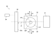
- 1 is a diagram schematically showing a preform analyzer according to an embodiment.
- 3 is a graph showing the relationship between the distance from the center of the optical fiber base material and the width of variation in refractive index distribution in Examples 1 to 3 and Comparative Examples 1 to 3.
- FIG. 1 is a diagram schematically showing a cross section perpendicular to the longitudinal direction of an optical fiber preform according to an embodiment of the present invention.
- the optical fiber preform 1P of this embodiment mainly includes a rod-shaped core glass body 10P and a clad glass body 11P surrounding the outer peripheral surface of the core glass body 10P.
- the core glass body 10P is a member that becomes the core of the optical fiber obtained from the optical fiber preform 1P
- the clad glass body 11P is a member that becomes the clad of the optical fiber obtained from the optical fiber preform 1P.
- the outer shape of the core glass body 10P and the outer shape of the clad glass body 11P in the cross section are approximately circular, and the core glass body 10P is arranged at the center of the clad glass body 11P. Further, the outer diameter of the core glass body 10P is 15 mm, and the outer diameter of the clad glass body 11P is 50 mm, but these outer diameters are not limited.
- FIG. 2 is a diagram schematically showing the refractive index distribution in a cross section perpendicular to the longitudinal direction of the optical fiber preform 1P shown in FIG. higher than
- the core glass body 10P is made of silica glass doped with a dopant that increases the refractive index, such as germanium (Ge)
- the clad glass body 11P is made of silica glass without any additives.
- the core glass body 10P may be made of silica glass without any additives
- the clad glass body 11P may be made of silica glass doped with a dopant that lowers the refractive index, such as fluorine (F).
- the core glass body 10P may be made of silica glass doped with a dopant that increases the refractive index
- the clad glass body 11P may be made of silica glass doped with a dopant that decreases the refractive index.
- the dopant that increases the refractive index and the dopant that decreases the refractive index are not limited.
- FIG. 3 is a conceptual diagram showing an enlarged part of the refractive index distribution shown in FIG. 2, and is a conceptual diagram showing an enlarged part of the refractive index distribution of the core glass body 10P.
- the refractive index distribution of the optical fiber preform 1P is a distribution including a fluctuation region in which fluctuations 20 in which the refractive index increases and decreases are repeated. That is, in the variable region, increasing regions where the refractive index increases and decreasing regions where the refractive index decreases are arranged alternately.
- the amount of increase and amount of decrease in the refractive index in this variation 20 is, for example, approximately 0.04% or less when the refractive index distribution is expressed as a relative refractive index.
- the width 20W of this variation 20 in the radial direction is, for example, about 0.3 mm to 0.3 ⁇ m.
- the width 20W of the fluctuation 20 is sometimes referred to as the width of the striae or the period of the striae, or the width of the repetition of the fluctuation 20 or the width of each layer constituting the striae.
- the optical fiber preform 1P is a sintered porous glass body in which glass fine particles are deposited in multiple layers. Therefore, a glass layer corresponding to each layer of glass fine particles is formed in the optical fiber preform 1P, and the refractive index distribution of the optical fiber preform 1P has minute refractive indexes corresponding to these glass layers.
- the refractive index distribution includes a fluctuation region in which the above fluctuations 20 are repeated.
- the entire refractive index distribution of the optical fiber preform 1P is a variable region.
- the radial width 20W of the fluctuation 20 in the outer region OR where the distance L from the center of the optical fiber preform 1P is 7 mm or more is less than 2 ⁇ m, and the width of the fluctuation 20 is closer to the center of the optical fiber preform 1P. 20W increases.
- the radial width 20W of the variation 20 in the entire outer region OR is less than 2 ⁇ m.
- the inner region IR where the distance L is less than 7 mm includes a region where the width 20W of the fluctuation 20 is 2 ⁇ m or more, but the inner region IR includes a region where the width 20W of the fluctuation 20 is 2 ⁇ m or more.
- the above areas may not be included.
- a part of the core glass body 10P is located in the outer region OR, but the core glass body 10P does not need to be located in the outer region OR. That is, the core glass body 10P may be located only in the inner region IR.
- FIG. 4 is a flowchart showing the steps of the method for manufacturing the optical fiber preform 1P according to the present embodiment. As shown in FIG. 4, the method for manufacturing the optical fiber preform 1P of this embodiment includes a glass member forming step P1 and a stretching step P2.
- ⁇ Glass member forming process P1> This process is a process of depositing glass particles in multiple layers on a glass rod that rotates around its axis to form a porous glass body, and sintering the porous glass body to form a rod-shaped glass member. .
- a porous glass body is formed by a VAD method in which glass fine particles are deposited in multiple layers in the axial direction of the glass rod from one end of the glass rod rotating around the axis.
- This porous glass body is sintered to form a rod-shaped glass member.
- the glass member thus formed has a configuration in which the optical fiber preform 1P shown in FIG. 1 is expanded in the radial direction and reduced in the longitudinal direction.
- the glass member is composed of a core glass body 10P and a clad glass body 11P, and the ratio of the outer diameter of the core glass body 10P to the outer diameter of the clad glass body 11P in the glass member is the same as that in the optical fiber base material 1P. It is roughly the same as the ratio.
- the refractive index distribution of the glass member is a distribution obtained by elongating the refractive index distribution of the optical fiber preform 1P shown in FIG. 2 in the radial direction. That is, to form such a glass member, glass particles are deposited in multiple layers to form a porous glass body, and the porous glass body is sintered.
- the rotational speed of the glass rod is constant, but the rotational speed of the glass rod may be changed while depositing the glass particles.
- the method for depositing the glass particles is not limited, and may be, for example, an OVD method in which glass particles are deposited in multiple layers on the outer circumferential surface of a glass rod that rotates around an axis.
- This step is a step in which the glass member formed in the glass member forming step P1 is heated and stretched in the longitudinal direction.
- the glass member formed in the glass member forming step P1 has a configuration in which the optical fiber preform 1P shown in FIG. 1 is expanded in the radial direction and reduced in the longitudinal direction. Therefore, by stretching the glass member in the longitudinal direction, the glass member becomes the optical fiber preform 1P.
- the stretching ratio of the glass member in the stretching step P2 increases, the width 20W of the fluctuation 20 in the refractive index distribution of the glass member after stretching becomes narrower.
- the stretching ratio is the ratio of the length of the glass member after stretching to the length of the glass member before stretching.
- the rotational speed of the glass rod in the glass member forming step P1 and the drawing rate of the glass member in the drawing step P2 are such that at least a part of the variation region in the refractive index distribution of the glass member after drawing is It is set so that the distance from the center is included in the outer region OR of 7 mm or more, and the width 20W of the fluctuation 20 in the outer region OR is less than 2 ⁇ m. Therefore, the refractive index distribution of the obtained optical fiber preform 1P includes a fluctuation region in which fluctuations 20 in which the refractive index increases and decreases are repeated.
- the fluctuation region is included in the outer region OR where the distance L from the center of the optical fiber preform 1P is 7 mm or more, and the radial width of the fluctuation 20 in the outer region OR is less than 2 ⁇ m.
- the rotation speed of the glass rod in the glass member forming step P1 is preferably 20 rpm or more and 40 rpm or less. According to such a configuration, it is possible to easily manufacture the optical fiber preform 1P in which the width of the fluctuation 20 in the outer region OR is less than 2 ⁇ m.
- FIG. 5 is a diagram schematically showing the preform analyzer according to this embodiment.
- the preform analyzer 30 includes a light emitting section 31 that emits light, a light receiving section 32 that receives light, a light transmissive housing section 33 having a housing space, and a light transmitting housing section 33 that has a housing space.
- the main components include a section 34.
- the light emitting unit 31 of this embodiment emits a laser beam with a peak power wavelength of 632 nm, but the peak power wavelength of the laser beam is not limited.
- the light receiving section 32 is an optical element that converts the light received by the light receiving surface 32s into an electrical signal and outputs it.
- the light-receiving surface 32s is composed of the light-receiving surfaces of a plurality of light-receiving elements that receive light. Output.
- An example of information related to the position of light is a two-dimensional image.
- the light emitting section 31 and the light receiving section 32 are arranged so as to face the light emitting section of the light emitting section 31 and the light receiving surface 32s of the light receiving section 32 with an interval therebetween.
- the housing section 33 is arranged between the light emitting section 31 and the light receiving section 32.
- the optical fiber preform 1P is accommodated in the accommodation space of the accommodation section 33 such that the longitudinal direction of the optical fiber preform 1P is perpendicular to the direction in which the light emitting section 31 and the light receiving section 32 face each other,
- the accommodation space is filled with matching oil 35 having the same refractive index as the clad glass body 11P.
- the accommodating part 33 is movable in a predetermined direction perpendicular to the longitudinal direction of the optical fiber preform 1P and perpendicular to the direction in which the light emitting part 31 and the light receiving part 32 face each other.
- the laser light emitted from the light emitting section 31 passes through the optical fiber base material 1P and is irradiated onto the light receiving surface 32s of the light receiving section 32.
- the diameter of the laser beam when incident on the optical fiber preform 1P is, for example, 20 ⁇ m or more and 40 ⁇ m or less, and in this embodiment, it is 30 ⁇ m.
- the laser beam is scanned by moving the housing section 33 in a predetermined direction.
- the predetermined direction is, for example, a direction perpendicular to the direction of incidence of the laser beam onto the optical fiber preform 1P and the longitudinal direction of the optical fiber preform 1P.
- the laser beam enters the optical fiber preform 1P accommodated in the housing section 33 from a direction perpendicular to the longitudinal direction of the optical fiber preform 1P.
- the optical fiber preform 1P moves in a direction D1 toward the center 1Pc of the optical fiber preform 1P or in a direction D2 away from the center 1Pc of the optical fiber preform 1P with respect to the light emitting part 31, and the laser beam is emitted. is scanned.
- the direction D1 toward the center 1Pc of the optical fiber base material 1P or the optical fiber base material is adjusted so that the laser beam enters the optical fiber base material 1P from a direction perpendicular to the longitudinal direction of the optical fiber base material 1P.
- the light emitting part 31 may move in the above predetermined direction
- the optical fiber preform 1P may move in the above predetermined direction
- the optical fiber preform 1P and the light emitting part 31 may move in the above predetermined direction. may be moved in a predetermined direction.
- the above-mentioned perpendicular includes not only perfect perpendicularity but also cases in which the optical fiber base material 1P is curved due to manufacturing errors and deviates from perfect perpendicularity, for example.
- the light receiving section 32 outputs information regarding the position of the laser beam irradiated onto the light receiving surface 32s to the measuring section 34.
- the measuring unit 34 measures the refraction angle ⁇ of the laser beam in the optical fiber base material 1P based on this information, and determines the refractive index of the position in the optical fiber base material 1P through which the laser beam passes based on the refraction angle ⁇ .
- the refractive index distribution is determined from this refractive index.
- the measurement unit 34 is composed of an integrated circuit such as a microcontroller, an IC (Integrated Circuit), an LSI (Large-scale Integrated Circuit), or an ASIC (Application Specific Integrated Circuit), or an NC (Numerical Control) device.
- such a preform analyzer 30 is used to measure the refractive distribution of the optical fiber preform 1P.
- the optical fiber preform 1P is accommodated in the accommodation space of the accommodation section 33 as described above.
- the light emitting section 31 emits laser light.
- the laser beam is directed toward the center 1Pc of the optical fiber base material 1P or away from the center 1Pc so that the laser beam enters the optical fiber base material 1P from a direction perpendicular to the longitudinal direction of the optical fiber base material 1P.
- the optical fiber preform 1P and the light emitting section 31 are moved relative to each other in the direction to scan the laser beam.
- the optical fiber preform 1P is moved relative to the light emitting part 31 by moving the housing part 33.
- the light receiving section 32 is caused to receive the laser light emitted from the optical fiber preform 1P.
- the light receiving unit 32 outputs information regarding the position of the light irradiated onto the light receiving surface 32s, and the measuring unit 34 measures the refraction angle ⁇ of the laser beam at the optical fiber base material 1P based on the two-dimensional image.
- the refractive index distribution of the optical fiber preform 1P is measured based on the refraction angle ⁇ .
- the preform analyzer 30 operates in a direction toward the center 1Pc of the optical fiber preform 1P so that the laser beam enters the optical fiber preform 1P from a direction perpendicular to the longitudinal direction of the optical fiber preform 1P.
- the optical fiber base material 1P and the light emitting part 31 are relatively moved in a direction away from the center 1Pc to scan the laser light, and the optical fiber is formed based on the refraction angle of the laser light emitted from the optical fiber base material 1P. Measure the refractive index distribution of the base material 1P.
- the optical fiber preform 1P of this embodiment has a refractive index distribution including a fluctuation region in which the refractive index repeats fluctuations 20 in which the refractive index increases and decreases. At least a part of this fluctuation region is included in the outer region OR where the distance L from the center of the optical fiber preform 1P is 7 mm or more, and the radial width of the fluctuation 20 in the outer region OR is less than 2 ⁇ m.
- the present inventor studied an optical fiber base material whose refractive index distribution cannot be measured with a preform analyzer. As a result, the farther the distance from the center of the optical fiber base material, the more difficult it is to accurately measure the refraction angle of the laser beam, and the shorter the distance, the easier it is to accurately measure the refraction angle of the laser beam. Do you get it. Furthermore, it has been found that even if this distance is long, it becomes easier to accurately measure the refraction angle of the laser beam if the range of variation in the refractive index is narrow.
- the inventor of the present invention found that the radial width of the above fluctuation in the outer region of the refractive index distribution where the distance from the center of the optical fiber base material is 7 mm or more is less than 2 ⁇ m. It has been found that in some cases it is possible to measure the refractive index distribution using a preform analyzer. Therefore, according to the optical fiber preform 1P of this embodiment, it is possible to prevent the preform analyzer from being unable to measure the refractive index distribution.
- the width 20W of the fluctuation 20 becomes larger toward the center.
- the width 20W of the above fluctuation 20 becomes larger toward the center. Therefore, the optical fiber preform 1P of this embodiment is suitable for the optical fiber preform manufactured in this manner. Note that the width 20W of the fluctuation 20 may be random in the radial direction or may be approximately constant.
- the optical fiber preform 1P of this embodiment is a preform that is drawn to obtain an optical fiber. Therefore, according to the optical fiber preform 1P of this embodiment, the conditions for drawing can be appropriately set, for example, based on the refractive index distribution measured by a preform analyzer. Note that the optical fiber preform 1P can also be used as a so-called intermediate preform for obtaining a preform having a diameter larger than that of the optical fiber preform 1P. By providing a glass layer on the outer peripheral surface of the optical fiber preform 1P as an intermediate preform, a preform having a diameter larger than that of the optical fiber preform 1P can be obtained.
- this glass layer is made of the same glass body as the clad glass body 11P, a base material having a larger outer diameter than the clad glass body 11P shown in FIG. 1 is obtained.
- the refractive index distribution of the optical fiber preform 1P can be measured with a preform analyzer, and the outer diameter of the glass layer can be set based on the refractive index distribution. Therefore, a base material having a desired ratio of the outer diameter of the core glass body 10P to the outer diameter of the clad glass body 11P can be obtained.
- the laser beam is incident on the optical fiber preform 1P from a direction perpendicular to the longitudinal direction of the optical fiber preform 1P.
- Laser light is generated by relatively moving the optical fiber base material 1P and the light emitting section 31 that emits laser light in the direction toward the center 1Pc of the fiber base material 1P or in the direction away from the center 1Pc of the optical fiber base material 1P. is scanned, and the refractive index distribution of the optical fiber preform 1P is measured based on the refraction angle of the laser beam emitted from the optical fiber preform 1P.
- the optical fiber preform 1P has a refractive index distribution including a fluctuation region in which fluctuations 20 in which the refractive index increases and decreases are repeated. At least a part of this fluctuation region is included in the outer region OR where the distance L from the center of the optical fiber preform 1P is 7 mm or more, and the radial width of the fluctuation 20 in the outer region OR is less than 2 ⁇ m.
- the diameter of the laser beam when incident on the optical fiber preform 1P is 20 ⁇ m or more and 40 ⁇ m or less. According to such a configuration, the refractive index distribution of the optical fiber preform 1P described above can be measured.
- the optical fiber preform 1P including the core glass body 10P and the clad glass body 11P was explained as an example.
- the optical fiber base material 1P has a refractive index distribution including a fluctuating region in which the refractive index repeats fluctuations 20 in which the refractive index increases and decreases, and at least a part of the fluctuating region has a distance L from the center of the optical fiber base material 1P. It is sufficient that the width 20W of the fluctuation 20 in the outer region OR is less than 2 ⁇ m and included in the outer region OR of 7 mm or more.
- the clad glass body 11P includes an inner glass layer surrounding the outer circumferential surface of the core glass body 10P and having a different refractive index from the core glass body 10P, and an outer glass layer surrounding the outer circumferential surface of the inner glass layer and having a different refractive index from the inner glass layer. It may be composed of.
- the optical fiber preform 1P may be the core glass body 10P.
- the optical fiber preform 1P is explained using an example in which the refractive index fluctuation 20 is repeated over the entire radial direction of the optical fiber preform 1P, and the entire refractive index distribution is a variation region. did. However, it is sufficient that at least a part of the variable region is included in the outer region OR where the distance L from the center of the optical fiber preform 1P is less than 7 mm. For example, the fluctuation 20 may not occur on the center side of the inner region IR where the distance L is less than 7 mm.
- Such an optical fiber preform 1P is obtained by forming a porous glass body by the OVD method using a glass rod in which no fluctuation 20 occurs in the refractive index distribution in the glass member forming step P1, for example. It is obtained by sintering the body to form a glass member.
- the optical fiber preform 1P includes a rod-shaped core glass body 10P and a clad glass body 11P that has a different refractive index from the core glass body 10P and surrounds the outer peripheral surface of the core glass body 10P. Be prepared. A part of the core glass body 10P is located in the outer region OR. However, as described above, the core glass body 10P may be located only in the inner region IR where the distance from the center of the optical fiber preform 1P is less than 7 mm. According to such a configuration, the width of the fluctuation 20 in the core glass body 10P is allowed to increase. Therefore, according to such a configuration, it is possible to realize an optical fiber preform 1P including a core glass body 10P with a high degree of freedom in the width 20W of the fluctuation 20.
- an optical fiber preform 1P shown in FIG. 1 was manufactured by the method for manufacturing an optical fiber preform shown in the above embodiment. Specifically, in the glass member forming step P1, a porous glass body is formed by a VAD method with a rotational speed of a glass rod, in other words, a rotation speed of 20 rpm, and the porous glass body is sintered to form a glass member. was formed. The outer diameter of this glass member was 100 mm. Further, in the drawing step P2, this glass member was drawn to produce an optical fiber preform 1P. The stretching ratio of the glass member in the stretching step P2 was approximately 2.0, the outer diameter of the optical fiber preform 1P was 50 mm, and the radius of the core glass body 10P was 7.5 mm.
- Example 2 An optical fiber preform 1P was produced in the same manner as in Example 1, except that the stretching rate of the glass member in the stretching step P2 was made larger than that in Example 1.
- the stretching ratio of the glass member in the drawing step P2 of this example is about 2.3
- the outer diameter of the optical fiber preform 1P of this example is 43 mm
- the radius of the core glass body 10P is 6.5 mm. there were. That is, the core glass body 10P of Example 2 was located only in the inner region IR.
- Example 3 The number of rotations of the glass rod in the glass member forming step P1, in other words, the rotation speed, was set to 40 rpm, and the stretching rate of the glass member in the stretching step P2 was made smaller than that in Example 1.
- An optical fiber base material 1P was manufactured.
- the stretching ratio of the glass member in the drawing step P2 of this example was about 1.9, the outer diameter of the optical fiber preform 1P of this example was 53 mm, and the radius of the core glass body 10P was 8 mm. .
- An optical fiber preform 1P was produced in the same manner as in Example 1, except that the stretching rate of the glass member in the stretching step P2 was set to a value different from the stretching rate in Example 1.
- the stretching ratio of the glass member in the stretching step P2 was about 1.6
- the outer diameter of the optical fiber preform 1P was 63 mm
- the radius of the core glass body 10P was 9.5 mm.
- the stretching ratio of the glass member in the stretching step P2 was about 1.8
- the outer diameter of the optical fiber preform 1P was 57 mm
- the radius of the core glass body 10P was 8.5 mm.
- the stretching ratio of the glass member in the stretching step P2 was about 1.9
- the outer diameter of the optical fiber preform 1P was 53 mm
- the radius of the core glass body 10P was 8 mm.
- the refractive index distribution of the optical fiber preforms 1P obtained in each of Examples 1 to 3 and Comparative Examples 1 to 3 was measured using a preform analyzer 30 shown in FIG.
- the peak wavelength of the power of the laser light in the preform analyzer 30 was 632 nm, and the diameter of the laser light when it entered the optical fiber base material 1P was approximately 30 ⁇ m.
- the relationship between the distance L from the center of the optical fiber base material 1P and the width 20W of the fluctuation 20 in the refractive index distribution I looked into it.
- the width 20W of the fluctuation 20 in the region where the distance L was 7 mm or more and 9.5 mm or less was less than 2 ⁇ m.
- the width 20W in the region where the distance L exceeds 9.5 mm was also less than 2 ⁇ m.
- the refractive index distribution of the optical fiber preform 1P could be measured.
- a range where the distance L is 7 mm or more and the width 20W of the fluctuation 20 is 2 ⁇ m or more is hatched with a plurality of dots.
- Comparative Example 1 the refraction angle of the laser beam emitted from the preform analyzer 30 could not be measured in a region where the distance L was 7.0 mm or more and 9.0 mm or less. Further, in Comparative Example 2, the refraction angle of the laser beam emitted from the preform analyzer 30 could not be measured in a region where the distance L was 7.0 mm or more and 8.0 mm or less. Furthermore, in Comparative Example 3, the refraction angle of the laser beam emitted from the preform analyzer 30 could not be measured in a region where the distance L was 7.0 mm or more and 7.5 mm or less. In Comparative Examples 1 to 3, the refractive index distribution could not be accurately measured. Although not shown in FIG.
- the width 20W of the fluctuation 20 in the region where the distance L exceeds 9.5 mm was less than 2 ⁇ m.
- the width 20W of the variation 20 becomes larger toward the center.
- the width 20W in the region where the distance L was less than 7.0 mm exceeded 2 ⁇ m.
- the width 20W decreases at a generally constant rate from the center side toward the outside, and in the area outside the distance L where the width 20W is approximately 1 ⁇ m, the width It can be seen that the rate at which 20W decreases becomes smaller.
- the preform analyzer 30 can measure the refractive index distribution when the width 20W in the entire region where the distance L is 7 mm or more is less than 2 ⁇ m. Further, it was found that the width 20W at a position where the distance L is 7 mm may be 1.8 ⁇ m or more and less than 2.0 ⁇ m.
- the refractive index distribution was measured using the laser beam of the preform analyzer 30 as a laser beam with a power peak wavelength of 405 nm, but the relationship between the distance L and the width 20W is the same as the results shown in FIG. 6 and Table 1. It was the same. Therefore, it is considered that the wavelength of the laser light from the preform analyzer 30 does not have much influence on whether or not the refractive index distribution can be measured. Further, the refractive index distribution was measured by changing the laser light of the preform analyzer 30 to white light emitted from an LED (Light Emitting Diode).
- LED Light Emitting Diode
- the degree of diffusion of the light emitted from the optical fiber base material is greater, but the refraction angle of the light can be measured, and the relationship between the distance L and the width 20W is as follows.
- the results were similar to those shown in FIG. 6 and Table 1. Therefore, it is considered that the diameter of light incident on the optical fiber preform does not have much influence on whether or not the refractive index distribution can be measured.
- the refractive index distribution is measured so that the diameter of the laser beam when it enters the optical fiber base material 1P is 20 ⁇ m, and when the refractive index distribution is measured so that this diameter is 40 ⁇ m, Even if there is, the relationship between the distance L and the width 20W is the same as the results shown in FIG. 6 and Table 1. Therefore, if the above-mentioned diameter is 20 ⁇ m or more and 40 ⁇ m or less, it is possible to measure the refractive index distribution of the optical fiber base material 1P in which the width 20W is less than 2 ⁇ m in the area where the distance L is 7 mm or more, similar to 30 ⁇ m. It is believed that there is.
- an optical fiber preform As explained above, according to the present invention, there is provided an optical fiber preform, a method for measuring the refractive index distribution of an optical fiber preform, and an optical A method for manufacturing a fiber preform is provided, and is expected to be used in fields such as optical fiber communications.
Landscapes
- Chemical & Material Sciences (AREA)
- Engineering & Computer Science (AREA)
- Life Sciences & Earth Sciences (AREA)
- General Life Sciences & Earth Sciences (AREA)
- Geochemistry & Mineralogy (AREA)
- Manufacturing & Machinery (AREA)
- Materials Engineering (AREA)
- Organic Chemistry (AREA)
- Chemical Kinetics & Catalysis (AREA)
- General Chemical & Material Sciences (AREA)
- Physics & Mathematics (AREA)
- Biochemistry (AREA)
- General Health & Medical Sciences (AREA)
- General Physics & Mathematics (AREA)
- Immunology (AREA)
- Pathology (AREA)
- Analytical Chemistry (AREA)
- Health & Medical Sciences (AREA)
- Manufacture, Treatment Of Glass Fibers (AREA)
Priority Applications (4)
| Application Number | Priority Date | Filing Date | Title |
|---|---|---|---|
| JP2024537709A JPWO2024024729A1 (https=) | 2022-07-26 | 2023-07-24 | |
| CN202380043360.7A CN119212956A (zh) | 2022-07-26 | 2023-07-24 | 光纤用母材、光纤用母材的折射率分布的测量方法以及光纤用母材的制造方法 |
| EP23846459.8A EP4563540A1 (en) | 2022-07-26 | 2023-07-24 | Preform for optical fibers, method for measuring refractive index profile of preform for optical fibers, and method for producing preform for optical fibers |
| US18/997,919 US20260029342A1 (en) | 2022-07-26 | 2023-07-24 | Optical fiber preform, method for measuring refractive index profile of optical fiber preform, and method for producing optical fiber preform |
Applications Claiming Priority (2)
| Application Number | Priority Date | Filing Date | Title |
|---|---|---|---|
| JP2022-118756 | 2022-07-26 | ||
| JP2022118756 | 2022-07-26 |
Publications (1)
| Publication Number | Publication Date |
|---|---|
| WO2024024729A1 true WO2024024729A1 (ja) | 2024-02-01 |
Family
ID=89706640
Family Applications (1)
| Application Number | Title | Priority Date | Filing Date |
|---|---|---|---|
| PCT/JP2023/027018 Ceased WO2024024729A1 (ja) | 2022-07-26 | 2023-07-24 | 光ファイバ用母材、光ファイバ用母材の屈折率分布の測定方法、及び光ファイバ用母材の製造方法 |
Country Status (5)
| Country | Link |
|---|---|
| US (1) | US20260029342A1 (https=) |
| EP (1) | EP4563540A1 (https=) |
| JP (1) | JPWO2024024729A1 (https=) |
| CN (1) | CN119212956A (https=) |
| WO (1) | WO2024024729A1 (https=) |
Citations (6)
| Publication number | Priority date | Publication date | Assignee | Title |
|---|---|---|---|---|
| JPS62167238A (ja) * | 1986-01-20 | 1987-07-23 | Sumitomo Electric Ind Ltd | 光フアイバ用母材の製造方法 |
| JPH11199263A (ja) * | 1998-01-06 | 1999-07-27 | Sumitomo Electric Ind Ltd | 光ファイバ母材製造方法 |
| JP2003277069A (ja) * | 2002-03-22 | 2003-10-02 | Fujikura Ltd | 多孔質母材の製造方法 |
| JP2013047165A (ja) * | 2011-08-29 | 2013-03-07 | Sumitomo Electric Ind Ltd | ガラス微粒子堆積体の製造方法及び光ファイバ用ガラス母材及び光ファイバ |
| JP2013056794A (ja) | 2011-09-07 | 2013-03-28 | Sumitomo Electric Ind Ltd | ガラス微粒子堆積体の製造方法及び光ファイバ用ガラス母材 |
| JP2013056786A (ja) * | 2011-09-07 | 2013-03-28 | Sumitomo Electric Ind Ltd | 光ファイバ用母材の製造方法 |
-
2023
- 2023-07-24 EP EP23846459.8A patent/EP4563540A1/en active Pending
- 2023-07-24 CN CN202380043360.7A patent/CN119212956A/zh active Pending
- 2023-07-24 WO PCT/JP2023/027018 patent/WO2024024729A1/ja not_active Ceased
- 2023-07-24 JP JP2024537709A patent/JPWO2024024729A1/ja active Pending
- 2023-07-24 US US18/997,919 patent/US20260029342A1/en active Pending
Patent Citations (6)
| Publication number | Priority date | Publication date | Assignee | Title |
|---|---|---|---|---|
| JPS62167238A (ja) * | 1986-01-20 | 1987-07-23 | Sumitomo Electric Ind Ltd | 光フアイバ用母材の製造方法 |
| JPH11199263A (ja) * | 1998-01-06 | 1999-07-27 | Sumitomo Electric Ind Ltd | 光ファイバ母材製造方法 |
| JP2003277069A (ja) * | 2002-03-22 | 2003-10-02 | Fujikura Ltd | 多孔質母材の製造方法 |
| JP2013047165A (ja) * | 2011-08-29 | 2013-03-07 | Sumitomo Electric Ind Ltd | ガラス微粒子堆積体の製造方法及び光ファイバ用ガラス母材及び光ファイバ |
| JP2013056794A (ja) | 2011-09-07 | 2013-03-28 | Sumitomo Electric Ind Ltd | ガラス微粒子堆積体の製造方法及び光ファイバ用ガラス母材 |
| JP2013056786A (ja) * | 2011-09-07 | 2013-03-28 | Sumitomo Electric Ind Ltd | 光ファイバ用母材の製造方法 |
Also Published As
| Publication number | Publication date |
|---|---|
| JPWO2024024729A1 (https=) | 2024-02-01 |
| US20260029342A1 (en) | 2026-01-29 |
| CN119212956A (zh) | 2024-12-27 |
| EP4563540A1 (en) | 2025-06-04 |
Similar Documents
| Publication | Publication Date | Title |
|---|---|---|
| CN102576123B (zh) | 精确形状的芯式光纤及其制造方法 | |
| CN102132178B (zh) | 双包层光纤和具有双包层光纤的设备 | |
| Pickrell et al. | Novel techniques for the fabrication of holey optical fibers | |
| US7379645B2 (en) | Optical fiber with fresnel diffraction | |
| JP6536036B2 (ja) | 光ファイバ | |
| CN102741183B (zh) | 石英多孔质体的制造方法、光纤母材的制造方法、石英多孔质体及光纤母材 | |
| EP1745316A1 (en) | Microstructured optical fibre | |
| EP2755066B1 (en) | Optical fiber, optical fiber preform and method of fabricating same | |
| EP1468316A1 (en) | Ring structures in optical fibres | |
| US11001520B2 (en) | Optical fiber glass preform manufacturing method | |
| JP2011513768A (ja) | オールソリッドフォトニックバンドギャップファイバ | |
| JP2012510643A (ja) | 改良された屈折率プロファイルを有する多重モード光ファイバー | |
| WO2024024729A1 (ja) | 光ファイバ用母材、光ファイバ用母材の屈折率分布の測定方法、及び光ファイバ用母材の製造方法 | |
| JP4659335B2 (ja) | 光学レンズ用母材、光学レンズ、及び光学レンズの製造方法 | |
| JPH07301600A (ja) | 一連の屈折率縞を含む光ファイバ・コア・ケ−ンを分析する方法および屈折率分布を有するコア・ケ−ンを分析する装置 | |
| CN1688900A (zh) | 渐变折射率透镜,它在远程通信应用装置中的使用及其制造方法 | |
| Langner et al. | Trends in specialty fiber optic materials: characterization and applications | |
| CN115151514A (zh) | 结构化二氧化硅包层二氧化硅光纤 | |
| Wang et al. | Wavelength Scale Singlet Achromatic Microlenses Based on High Refractive Index Materials | |
| CN111650690A (zh) | 一种基于双包层光纤的微准直器 | |
| Niu et al. | Quasi-single-mode signal output of sapphire fibre Bragg grating based on single mode fibre offset coupling measurement | |
| JP3860164B2 (ja) | 非円率の測定方法 | |
| JP2024011344A (ja) | 光ファイバ用母材の製造方法 | |
| CN119146862A (zh) | 一种光学系统及预制棒分析系统 | |
| AU2002226190B2 (en) | An optical fibre |
Legal Events
| Date | Code | Title | Description |
|---|---|---|---|
| 121 | Ep: the epo has been informed by wipo that ep was designated in this application |
Ref document number: 23846459 Country of ref document: EP Kind code of ref document: A1 |
|
| WWE | Wipo information: entry into national phase |
Ref document number: 202380043360.7 Country of ref document: CN |
|
| WWP | Wipo information: published in national office |
Ref document number: 202380043360.7 Country of ref document: CN |
|
| WWE | Wipo information: entry into national phase |
Ref document number: 2024537709 Country of ref document: JP |
|
| WWE | Wipo information: entry into national phase |
Ref document number: 18997919 Country of ref document: US |
|
| WWE | Wipo information: entry into national phase |
Ref document number: 202517013563 Country of ref document: IN |
|
| WWE | Wipo information: entry into national phase |
Ref document number: 2023846459 Country of ref document: EP |
|
| NENP | Non-entry into the national phase |
Ref country code: DE |
|
| ENP | Entry into the national phase |
Ref document number: 2023846459 Country of ref document: EP Effective date: 20250226 |
|
| WWP | Wipo information: published in national office |
Ref document number: 202517013563 Country of ref document: IN |
|
| WWP | Wipo information: published in national office |
Ref document number: 2023846459 Country of ref document: EP |
|
| WWP | Wipo information: published in national office |
Ref document number: 18997919 Country of ref document: US |