WO2024024572A1 - Co2分離システム - Google Patents
Co2分離システム Download PDFInfo
- Publication number
- WO2024024572A1 WO2024024572A1 PCT/JP2023/026275 JP2023026275W WO2024024572A1 WO 2024024572 A1 WO2024024572 A1 WO 2024024572A1 JP 2023026275 W JP2023026275 W JP 2023026275W WO 2024024572 A1 WO2024024572 A1 WO 2024024572A1
- Authority
- WO
- WIPO (PCT)
- Prior art keywords
- gas
- separation
- equipment
- adsorption tower
- adsorption
- Prior art date
- Legal status (The legal status is an assumption and is not a legal conclusion. Google has not performed a legal analysis and makes no representation as to the accuracy of the status listed.)
- Ceased
Links
Images
Classifications
-
- F—MECHANICAL ENGINEERING; LIGHTING; HEATING; WEAPONS; BLASTING
- F25—REFRIGERATION OR COOLING; COMBINED HEATING AND REFRIGERATION SYSTEMS; HEAT PUMP SYSTEMS; MANUFACTURE OR STORAGE OF ICE; LIQUEFACTION SOLIDIFICATION OF GASES
- F25J—LIQUEFACTION, SOLIDIFICATION OR SEPARATION OF GASES OR GASEOUS OR LIQUEFIED GASEOUS MIXTURES BY PRESSURE AND COLD TREATMENT OR BY BRINGING THEM INTO THE SUPERCRITICAL STATE
- F25J3/00—Processes or apparatus for separating the constituents of gaseous or liquefied gaseous mixtures involving the use of liquefaction or solidification
- F25J3/06—Processes or apparatus for separating the constituents of gaseous or liquefied gaseous mixtures involving the use of liquefaction or solidification by partial condensation
- F25J3/063—Processes or apparatus for separating the constituents of gaseous or liquefied gaseous mixtures involving the use of liquefaction or solidification by partial condensation characterised by the separated product stream
- F25J3/067—Processes or apparatus for separating the constituents of gaseous or liquefied gaseous mixtures involving the use of liquefaction or solidification by partial condensation characterised by the separated product stream separation of carbon dioxide
-
- B—PERFORMING OPERATIONS; TRANSPORTING
- B01—PHYSICAL OR CHEMICAL PROCESSES OR APPARATUS IN GENERAL
- B01D—SEPARATION
- B01D53/00—Separation of gases or vapours; Recovering vapours of volatile solvents from gases; Chemical or biological purification of waste gases, e.g. engine exhaust gases, smoke, fumes, flue gases, aerosols
- B01D53/002—Separation of gases or vapours; Recovering vapours of volatile solvents from gases; Chemical or biological purification of waste gases, e.g. engine exhaust gases, smoke, fumes, flue gases, aerosols by condensation
-
- B—PERFORMING OPERATIONS; TRANSPORTING
- B01—PHYSICAL OR CHEMICAL PROCESSES OR APPARATUS IN GENERAL
- B01D—SEPARATION
- B01D53/00—Separation of gases or vapours; Recovering vapours of volatile solvents from gases; Chemical or biological purification of waste gases, e.g. engine exhaust gases, smoke, fumes, flue gases, aerosols
- B01D53/02—Separation of gases or vapours; Recovering vapours of volatile solvents from gases; Chemical or biological purification of waste gases, e.g. engine exhaust gases, smoke, fumes, flue gases, aerosols by adsorption, e.g. preparative gas chromatography
- B01D53/04—Separation of gases or vapours; Recovering vapours of volatile solvents from gases; Chemical or biological purification of waste gases, e.g. engine exhaust gases, smoke, fumes, flue gases, aerosols by adsorption, e.g. preparative gas chromatography with stationary adsorbents
- B01D53/0407—Constructional details of adsorbing systems
-
- C—CHEMISTRY; METALLURGY
- C01—INORGANIC CHEMISTRY
- C01B—NON-METALLIC ELEMENTS; COMPOUNDS THEREOF; METALLOIDS OR COMPOUNDS THEREOF NOT COVERED BY SUBCLASS C01C
- C01B32/00—Carbon; Compounds thereof
- C01B32/50—Carbon dioxide
-
- F—MECHANICAL ENGINEERING; LIGHTING; HEATING; WEAPONS; BLASTING
- F25—REFRIGERATION OR COOLING; COMBINED HEATING AND REFRIGERATION SYSTEMS; HEAT PUMP SYSTEMS; MANUFACTURE OR STORAGE OF ICE; LIQUEFACTION SOLIDIFICATION OF GASES
- F25J—LIQUEFACTION, SOLIDIFICATION OR SEPARATION OF GASES OR GASEOUS OR LIQUEFIED GASEOUS MIXTURES BY PRESSURE AND COLD TREATMENT OR BY BRINGING THEM INTO THE SUPERCRITICAL STATE
- F25J3/00—Processes or apparatus for separating the constituents of gaseous or liquefied gaseous mixtures involving the use of liquefaction or solidification
- F25J3/06—Processes or apparatus for separating the constituents of gaseous or liquefied gaseous mixtures involving the use of liquefaction or solidification by partial condensation
- F25J3/0605—Processes or apparatus for separating the constituents of gaseous or liquefied gaseous mixtures involving the use of liquefaction or solidification by partial condensation characterised by the feed stream
- F25J3/061—Natural gas or substitute natural gas
-
- F—MECHANICAL ENGINEERING; LIGHTING; HEATING; WEAPONS; BLASTING
- F25—REFRIGERATION OR COOLING; COMBINED HEATING AND REFRIGERATION SYSTEMS; HEAT PUMP SYSTEMS; MANUFACTURE OR STORAGE OF ICE; LIQUEFACTION SOLIDIFICATION OF GASES
- F25J—LIQUEFACTION, SOLIDIFICATION OR SEPARATION OF GASES OR GASEOUS OR LIQUEFIED GASEOUS MIXTURES BY PRESSURE AND COLD TREATMENT OR BY BRINGING THEM INTO THE SUPERCRITICAL STATE
- F25J3/00—Processes or apparatus for separating the constituents of gaseous or liquefied gaseous mixtures involving the use of liquefaction or solidification
- F25J3/06—Processes or apparatus for separating the constituents of gaseous or liquefied gaseous mixtures involving the use of liquefaction or solidification by partial condensation
- F25J3/063—Processes or apparatus for separating the constituents of gaseous or liquefied gaseous mixtures involving the use of liquefaction or solidification by partial condensation characterised by the separated product stream
- F25J3/0635—Processes or apparatus for separating the constituents of gaseous or liquefied gaseous mixtures involving the use of liquefaction or solidification by partial condensation characterised by the separated product stream separation of CnHm with 1 carbon atom or more
-
- B—PERFORMING OPERATIONS; TRANSPORTING
- B01—PHYSICAL OR CHEMICAL PROCESSES OR APPARATUS IN GENERAL
- B01D—SEPARATION
- B01D2256/00—Main component in the product gas stream after treatment
- B01D2256/24—Hydrocarbons
- B01D2256/245—Methane
-
- B—PERFORMING OPERATIONS; TRANSPORTING
- B01—PHYSICAL OR CHEMICAL PROCESSES OR APPARATUS IN GENERAL
- B01D—SEPARATION
- B01D2257/00—Components to be removed
- B01D2257/50—Carbon oxides
- B01D2257/504—Carbon dioxide
-
- B—PERFORMING OPERATIONS; TRANSPORTING
- B01—PHYSICAL OR CHEMICAL PROCESSES OR APPARATUS IN GENERAL
- B01D—SEPARATION
- B01D2257/00—Components to be removed
- B01D2257/80—Water
-
- F—MECHANICAL ENGINEERING; LIGHTING; HEATING; WEAPONS; BLASTING
- F25—REFRIGERATION OR COOLING; COMBINED HEATING AND REFRIGERATION SYSTEMS; HEAT PUMP SYSTEMS; MANUFACTURE OR STORAGE OF ICE; LIQUEFACTION SOLIDIFICATION OF GASES
- F25J—LIQUEFACTION, SOLIDIFICATION OR SEPARATION OF GASES OR GASEOUS OR LIQUEFIED GASEOUS MIXTURES BY PRESSURE AND COLD TREATMENT OR BY BRINGING THEM INTO THE SUPERCRITICAL STATE
- F25J2205/00—Processes or apparatus using other separation and/or other processing means
- F25J2205/40—Processes or apparatus using other separation and/or other processing means using hybrid system, i.e. combining cryogenic and non-cryogenic separation techniques
-
- F—MECHANICAL ENGINEERING; LIGHTING; HEATING; WEAPONS; BLASTING
- F25—REFRIGERATION OR COOLING; COMBINED HEATING AND REFRIGERATION SYSTEMS; HEAT PUMP SYSTEMS; MANUFACTURE OR STORAGE OF ICE; LIQUEFACTION SOLIDIFICATION OF GASES
- F25J—LIQUEFACTION, SOLIDIFICATION OR SEPARATION OF GASES OR GASEOUS OR LIQUEFIED GASEOUS MIXTURES BY PRESSURE AND COLD TREATMENT OR BY BRINGING THEM INTO THE SUPERCRITICAL STATE
- F25J2205/00—Processes or apparatus using other separation and/or other processing means
- F25J2205/60—Processes or apparatus using other separation and/or other processing means using adsorption on solid adsorbents, e.g. by temperature-swing adsorption [TSA] at the hot or cold end
-
- F—MECHANICAL ENGINEERING; LIGHTING; HEATING; WEAPONS; BLASTING
- F25—REFRIGERATION OR COOLING; COMBINED HEATING AND REFRIGERATION SYSTEMS; HEAT PUMP SYSTEMS; MANUFACTURE OR STORAGE OF ICE; LIQUEFACTION SOLIDIFICATION OF GASES
- F25J—LIQUEFACTION, SOLIDIFICATION OR SEPARATION OF GASES OR GASEOUS OR LIQUEFIED GASEOUS MIXTURES BY PRESSURE AND COLD TREATMENT OR BY BRINGING THEM INTO THE SUPERCRITICAL STATE
- F25J2210/00—Processes characterised by the type or other details of the feed stream
- F25J2210/04—Mixing or blending of fluids with the feed stream
-
- F—MECHANICAL ENGINEERING; LIGHTING; HEATING; WEAPONS; BLASTING
- F25—REFRIGERATION OR COOLING; COMBINED HEATING AND REFRIGERATION SYSTEMS; HEAT PUMP SYSTEMS; MANUFACTURE OR STORAGE OF ICE; LIQUEFACTION SOLIDIFICATION OF GASES
- F25J—LIQUEFACTION, SOLIDIFICATION OR SEPARATION OF GASES OR GASEOUS OR LIQUEFIED GASEOUS MIXTURES BY PRESSURE AND COLD TREATMENT OR BY BRINGING THEM INTO THE SUPERCRITICAL STATE
- F25J2215/00—Processes characterised by the type or other details of the product stream
- F25J2215/04—Recovery of liquid products
-
- F—MECHANICAL ENGINEERING; LIGHTING; HEATING; WEAPONS; BLASTING
- F25—REFRIGERATION OR COOLING; COMBINED HEATING AND REFRIGERATION SYSTEMS; HEAT PUMP SYSTEMS; MANUFACTURE OR STORAGE OF ICE; LIQUEFACTION SOLIDIFICATION OF GASES
- F25J—LIQUEFACTION, SOLIDIFICATION OR SEPARATION OF GASES OR GASEOUS OR LIQUEFIED GASEOUS MIXTURES BY PRESSURE AND COLD TREATMENT OR BY BRINGING THEM INTO THE SUPERCRITICAL STATE
- F25J2230/00—Processes or apparatus involving steps for increasing the pressure of gaseous process streams
- F25J2230/30—Compression of the feed stream
-
- F—MECHANICAL ENGINEERING; LIGHTING; HEATING; WEAPONS; BLASTING
- F25—REFRIGERATION OR COOLING; COMBINED HEATING AND REFRIGERATION SYSTEMS; HEAT PUMP SYSTEMS; MANUFACTURE OR STORAGE OF ICE; LIQUEFACTION SOLIDIFICATION OF GASES
- F25J—LIQUEFACTION, SOLIDIFICATION OR SEPARATION OF GASES OR GASEOUS OR LIQUEFIED GASEOUS MIXTURES BY PRESSURE AND COLD TREATMENT OR BY BRINGING THEM INTO THE SUPERCRITICAL STATE
- F25J2240/00—Processes or apparatus involving steps for expanding of process streams
- F25J2240/40—Expansion without extracting work, i.e. isenthalpic throttling, e.g. JT valve, regulating valve or venturi, or isentropic nozzle, e.g. Laval
-
- F—MECHANICAL ENGINEERING; LIGHTING; HEATING; WEAPONS; BLASTING
- F25—REFRIGERATION OR COOLING; COMBINED HEATING AND REFRIGERATION SYSTEMS; HEAT PUMP SYSTEMS; MANUFACTURE OR STORAGE OF ICE; LIQUEFACTION SOLIDIFICATION OF GASES
- F25J—LIQUEFACTION, SOLIDIFICATION OR SEPARATION OF GASES OR GASEOUS OR LIQUEFIED GASEOUS MIXTURES BY PRESSURE AND COLD TREATMENT OR BY BRINGING THEM INTO THE SUPERCRITICAL STATE
- F25J2245/00—Processes or apparatus involving steps for recycling of process streams
- F25J2245/02—Recycle of a stream in general, e.g. a by-pass stream
-
- F—MECHANICAL ENGINEERING; LIGHTING; HEATING; WEAPONS; BLASTING
- F25—REFRIGERATION OR COOLING; COMBINED HEATING AND REFRIGERATION SYSTEMS; HEAT PUMP SYSTEMS; MANUFACTURE OR STORAGE OF ICE; LIQUEFACTION SOLIDIFICATION OF GASES
- F25J—LIQUEFACTION, SOLIDIFICATION OR SEPARATION OF GASES OR GASEOUS OR LIQUEFIED GASEOUS MIXTURES BY PRESSURE AND COLD TREATMENT OR BY BRINGING THEM INTO THE SUPERCRITICAL STATE
- F25J2270/00—Refrigeration techniques used
- F25J2270/12—External refrigeration with liquid vaporising loop
-
- F—MECHANICAL ENGINEERING; LIGHTING; HEATING; WEAPONS; BLASTING
- F25—REFRIGERATION OR COOLING; COMBINED HEATING AND REFRIGERATION SYSTEMS; HEAT PUMP SYSTEMS; MANUFACTURE OR STORAGE OF ICE; LIQUEFACTION SOLIDIFICATION OF GASES
- F25J—LIQUEFACTION, SOLIDIFICATION OR SEPARATION OF GASES OR GASEOUS OR LIQUEFIED GASEOUS MIXTURES BY PRESSURE AND COLD TREATMENT OR BY BRINGING THEM INTO THE SUPERCRITICAL STATE
- F25J2270/00—Refrigeration techniques used
- F25J2270/80—Quasi-closed internal or closed external carbon dioxide refrigeration cycle
-
- F—MECHANICAL ENGINEERING; LIGHTING; HEATING; WEAPONS; BLASTING
- F25—REFRIGERATION OR COOLING; COMBINED HEATING AND REFRIGERATION SYSTEMS; HEAT PUMP SYSTEMS; MANUFACTURE OR STORAGE OF ICE; LIQUEFACTION SOLIDIFICATION OF GASES
- F25J—LIQUEFACTION, SOLIDIFICATION OR SEPARATION OF GASES OR GASEOUS OR LIQUEFIED GASEOUS MIXTURES BY PRESSURE AND COLD TREATMENT OR BY BRINGING THEM INTO THE SUPERCRITICAL STATE
- F25J2290/00—Other details not covered by groups F25J2200/00 - F25J2280/00
- F25J2290/62—Details of storing a fluid in a tank
-
- Y—GENERAL TAGGING OF NEW TECHNOLOGICAL DEVELOPMENTS; GENERAL TAGGING OF CROSS-SECTIONAL TECHNOLOGIES SPANNING OVER SEVERAL SECTIONS OF THE IPC; TECHNICAL SUBJECTS COVERED BY FORMER USPC CROSS-REFERENCE ART COLLECTIONS [XRACs] AND DIGESTS
- Y02—TECHNOLOGIES OR APPLICATIONS FOR MITIGATION OR ADAPTATION AGAINST CLIMATE CHANGE
- Y02C—CAPTURE, STORAGE, SEQUESTRATION OR DISPOSAL OF GREENHOUSE GASES [GHG]
- Y02C20/00—Capture or disposal of greenhouse gases
- Y02C20/40—Capture or disposal of greenhouse gases of CO2
Definitions
- the present invention relates to a CO2 separation system.
- separation processes for natural gas and associated gas can be classified as follows depending on CO 2 concentration.
- CO 2 concentration is 2% or less In this case, it is not necessary to separate CO 2 . This is because when the CO 2 concentration is 2% or less, the influence of pipeline corrosion is small.
- an AGR Acid Gas Removal
- the CO 2 concentration is around 30% In old equipment, molten potassium carbonate was used, but this is being replaced by the AGR process using an amine solvent. With amine solvents, the adsorbent can be regenerated by heat, and equipment maintenance is easy. On the other hand, with molten potassium carbonate, corrosion of steel is often a problem.
- an object of the present invention is to provide a CO 2 separation system that efficiently separates CO 2 with low energy from natural gas and biogas containing high concentrations of CO 2 and supplies a desired gas such as methane.
- the goal is to provide the following.
- a gas comprising a first CO 2 separation facility, a second CO 2 separation facility, a first pipe, a low concentration CO 2 gas discharge facility, a second pipe, and a high concentration CO 2 gas discharge device.
- the first CO 2 separation equipment includes a cryogenic separator that separates CO 2 from the gas to be treated by cryogenic separation processing
- the first piping has a 2.
- the gas discharged from the separation equipment is supplied to the second CO 2 separation equipment, and the second CO 2 separation equipment is equipped with an adsorption separation device including rubber as a CO 2 adsorbent, and the second CO 2 separation equipment is equipped with an adsorption separation device including rubber as a CO 2 adsorbent, and
- the gas exhaust equipment discharges gas containing low concentration CO 2 from the second CO 2 separation equipment, and the high concentration CO 2 gas exhaust equipment discharges gas containing low concentration CO 2 from the second CO 2 separation equipment.
- a gas containing a higher concentration of CO 2 is discharged, and in the gas reflux equipment, at least a part of the gas discharged from the high concentration CO 2 gas discharge device is transferred to the first pipe through the second pipe.
- the first CO 2 separation equipment is a CO 2 separation system that performs a cryogenic separation process to separate CO 2 from the gas returned by the gas reflux equipment.
- the second CO 2 separation equipment has a first adsorption tower group consisting of one or more adsorption towers and a second adsorption tower group consisting of one or more adsorption towers, and the adsorption tower has internal
- the CO 2 separation system includes a flow path through which gas is allowed to flow while remaining therein, and the CO 2 adsorbent, and the CO 2 separation system further includes a cooling means capable of cooling the flow path and the CO 2 adsorption material. , CO 2 separation system according to Configuration 1.
- the cryogenic separation device includes a compression device that compresses the supplied gas, a cooling device that cools the gas introduced through the compression device, and a device that discharges the CO 2 that has been liquefied after being cooled.
- CO 2 separation system according to configuration 1.
- Configuration 15 15. The CO 2 separation system according to any one of configurations 1 to 14, wherein the gas to be treated is introduced into the cryogenic separation device via dehydration equipment that performs dehydration.
- a CO 2 separation system that efficiently separates CO 2 from natural gas, biogas, etc. containing a high concentration of CO 2 with low energy, and supplies a desired gas such as methane.
- FIG. 1 is a system configuration diagram showing the overall configuration of a CO 2 separation system of the present invention.
- FIG. 1 is a configuration diagram showing the configuration of a first CO 2 separation facility that is part of the CO 2 separation system of the present invention. It is a block diagram which shows the structure of the 2nd CO2 separation equipment which is a part of CO2 separation system of this invention.
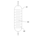
- FIG. 2 is a sectional view showing the structure of an adsorption tower.
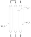
- FIG. 2 is an explanatory diagram illustrating the configuration of an adsorption tower.
- FIG. 2 is a characteristic diagram showing adsorption and desorption characteristics of CO 2 using rubber.
- FIG. 2 is a characteristic diagram showing the relationship between absolute pressure and CO 2 adsorption amount. It is a figure showing a breakthrough curve concerning an example.
- the CO 2 separation system 101 of this embodiment includes a first CO 2 separation equipment 1, which is a cryogenic separator, a second CO 2 separation equipment 2, and a pipe 14 (“first 2), a low-concentration CO 2 gas exhaust equipment 60, a gas reflux equipment 70 including a reflux piping 16 (an example of a ⁇ second piping''), and a high-concentration CO 2 gas exhaust device 45.
- FIG. 1 illustrates a configuration in which the CO 2 separation system 101 further includes a pressure reduction facility 4, a dehydration facility 5, and piping 11 to 13.
- the CO 2 separation system 101 include the pressure reduction equipment 4 and the dehydration equipment 5. Both or any one of the decompression equipment 4 and the dehydration equipment 5 may be omitted from the CO 2 separation system 101.
- the gas from which CO 2 is separated by the CO 2 separation system 101 will be referred to as “processed gas”.
- the gas to be treated is, for example, natural gas or associated gas, and includes CO 2 in addition to desired components (eg, methane).
- the cooling equipment 3 is capable of efficiently and precisely cooling the first CO 2 separation equipment 1 and the second CO 2 separation equipment 2.
- the cooling equipment 3 is capable of efficiently and precisely cooling the first CO 2 separation equipment 1 and the second CO 2 separation equipment 2.
- a vapor compression type refrigerator can be used, and as the refrigerant, although there is no particular restriction, CO2 can be used.
- the gas to be treated is supplied to the first CO 2 separation facility 1 via the pressure reduction facility 4 and the dehydration facility 5, for example. First, the gas to be treated is supplied to the decompression equipment 4 via the pipe 11. Next, the gas to be treated that has passed through the decompression equipment 4 is supplied to the dehydration equipment 5 via the pipe 12.
- the gas to be treated that has passed through the dehydration equipment 5 is supplied to the first CO 2 separation equipment 1 via the pipe 13.
- the first CO 2 separation facility 1 is connected to the second separation facility 2 through a pipe 14 .
- a reflux pipe 16 for refluxing a part of the gas treated in the second separation equipment 2 to the first separation equipment 1 is connected to the second separation equipment 2 and the first separation equipment 1.
- the first CO 2 separation equipment 1 includes a discharge pipe 17 that discharges liquid CO 2 and other condensable gases that are processed and generated in the first CO 2 separation equipment 1.
- the decompression equipment 4 is equipment provided for the purpose of reducing the pressure of the gas to be processed at a high pressure of 60 MPa or more (for example, high-pressure gas rising from deep underground), and includes, for example, a choke and a temperature adjustment device.
- a choke for example, if the gas to be treated has an initial pressure close to 120 MPa and contains water, methane hydrate will be formed if it is rapidly cooled by reduced pressure, so a temperature control device is required to prevent this. becomes.
- the pressure is often reduced stepwise, for example from 120 MPa to 60 MPa, 15 MPa, 3 MPa, etc., while maintaining the temperature above room temperature.
- the decompression equipment 4 may be provided with piping for discharging CO 2 , since liquid CO 2 is generated by appropriate depressurization. Furthermore, in the depressurizing equipment 4, water and condensate (liquid hydrocarbons) may be generated by cooling, and water and condensate can also be discharged from the piping that discharges CO2 . If the gas to be treated is natural gas containing condensate, it is desirable to discharge the valuable condensate.
- the dehydration equipment 5 is equipment provided for the purpose of removing moisture from the gas to be treated.
- the dehydration equipment 5 has a removing agent that removes moisture from the gas to be treated.
- the water removing agent molecular sieve (zeolite, registered trademark), silica gel, activated carbon, activated alumina, ethylene glycol derivatives, etc. can be used.
- dehydration equipment 5 using silica gel or activated alumina that can achieve a dew point of about -40°C can be suitably used.
- the water in the gas to be treated becomes almost liquid when the temperature is lowered, and in the dehydration equipment 5 it is used to remove water in the gas phase that does not coagulate even near room temperature.
- the dewatering equipment 5 may be equipped with a heater and a desorption steam cooler to regenerate the water removing agent. Further, it is desirable that the dehydration equipment 5 be operated at a temperature of 0° C. or higher to prevent the formation of hydrates. Moreover, in the case of continuous operation, the dehydration equipment 5 includes a plurality of adsorption towers. For example, the dehydration equipment 5 is provided when the gas to be treated is natural gas.
- the first CO 2 separation equipment 1 is a device that performs cryogenic separation processing to separate CO 2 from the gas to be processed.
- the first CO 2 separation equipment 1 is a cryogenic cooling system normally used, except that it has a path through which at least a part of the gas refluxed through the reflux pipe 16 is treated in the first CO 2 separation equipment 1. Separation equipment can be used.
- FIG. 2 is a configuration diagram of an example of the first CO 2 separation equipment 1 of this embodiment.
- the first CO 2 separation facility 1 includes, for example, a compression device 21, a dehydration device 22, a cooling device 23, and a liquefied CO 2 discharge device 24. .
- the compression device 21 is connected to a pipe 13 for supplying the gas to be processed and a reflux pipe 16 to which the gas refluxed from the second CO 2 separation equipment 2 is supplied.
- the gas compressed by the compression device 21 is supplied to the dehydration device 22 via the piping 31.
- the pressure of the gas after the compression treatment is, for example, 10 MPa or more and 50 MPa or less. Since compressing the gas increases its temperature, the first CO 2 separation facility 1 is preferably equipped with a cooling device 23 .
- the dehydration device 22 is a device that performs a dry gasification process (dehydration process) that removes moisture from the gas after the compression process.
- a dry gasification method a method using silica gel or zeolite is excellent.
- the amount of water contained in the dry gas subjected to the dry gasification treatment is controlled to be 10 ppm or less.
- dehydration using silica gel is desirably carried out at a temperature of 30° C. or lower, since the amount of adsorption decreases at high temperatures.
- the dehydration device 22 may be omitted.
- the dry gasified gas is supplied to the cooling device 23 via the piping 32.
- the cooling device 23 is not particularly limited, but for example, a vapor compression refrigerator may be used using CO 2 as a refrigerant, and its cold energy may be utilized.
- cooling by adiabatic expansion can also be used in combination within a range where CO 2 does not solidify.
- the cooling device 23 cools the supplied gas to -40°C or higher and 0°C or lower. Since the gas supplied to the cooling device 23 has already been dehydrated and no hydrate is formed, the temperature of the cooling device 23 is desirably low enough to prevent solidification of CO 2 . Further, the pressure is 10 MPa or more and 50 MPa or less, but it is desirable that the pressure be as high as possible to ensure the safety of the pressure container.
- the cooled gas is conveyed to the liquefied CO 2 discharge device 24 via the pipe 33, and liquid substances such as liquid CO 2 generated by cooling are discharged through the discharge pipe 17.
- the liquefied CO 2 discharge device 24 is a pump that discharges liquid CO 2 and, like the cooling device 23, needs to be cooled by the cooling equipment 3.
- FIG. 3 is a configuration diagram of an example of the second CO 2 separation equipment 2 according to the present embodiment.
- the second CO 2 separation facility 2 is a facility for removing CO 2 that has not been completely separated in the cryogenic separation process in the first CO 2 separation facility 1 .
- the second CO 2 separation equipment 2 includes an adsorption separation device 80 that uses rubber as an adsorbent.
- the adsorption separation device 80 is a device that adsorbs and separates CO 2 in the gas supplied from the pipe 14 and desorbs CO 2 .
- the adsorption separation device 80 includes, for example, two adsorption towers 41 (adsorption towers 41a, 41b) that incorporate rubber, which will be described later, as a CO 2 adsorbent. Note that if there is no need to distinguish between the adsorption tower 41a and the adsorption tower 41b, they will be referred to as adsorption tower 41.
- the number of adsorption towers 41 that the adsorption separation device 80 has is not limited to two towers, and may be three or more towers or one tower. However, from the viewpoint of continuously processing the gas to be treated, the number of adsorption towers 41 is preferably two or more.
- the adsorption tower 41 contains rubber, which is a CO 2 adsorbent, and adsorbs and desorbs CO 2 .
- the adsorption tower 41a and the adsorption tower 41b are the same and are arranged as a pair.
- the gas processed in the first CO 2 separation equipment 1 is switched and introduced into either the adsorption tower 41a or the adsorption tower 41b via the pipe 14 and the valve 51.
- the adsorption tower 41a and the adsorption tower 41b are connected to the reflux pipe 16 via a valve 52 and a high concentration CO 2 gas discharge device 45. Further, the adsorption tower 41a and the adsorption tower 41b are connected to the pipe 15 via a valve 53 and a flow rate regulator 46.
- one of the adsorption towers 41a and 41b is used for CO 2 adsorption, and the other is used for CO 2 desorption. That is, CO 2 adsorption and CO 2 desorption are performed in parallel. CO2 adsorption and CO2 desorption in the adsorption tower 41a are performed alternately, and CO2 adsorption and CO2 desorption in the adsorption tower 41b are performed alternately.
- Valve 51 is opened to the adsorption tower 41a side, closed to the adsorption tower 41b side, valve 52 is closed to the adsorption tower 41a side, and opened to the adsorption tower 41b side, valve 53 is opened to the adsorption tower 41a side, and closed to the adsorption tower 41b side.
- the adsorption tower 41a is used for CO 2 adsorption
- the adsorption tower 41b is used for CO 2 desorption.
- valve 51 is closed to the adsorption tower 41a side, opened to the adsorption tower 41b side
- valve 52 is opened to the adsorption tower 41a side, closed to the adsorption tower 41b side
- valve 53 is closed to the adsorption tower 41a side
- valve 53 is closed to the adsorption tower 41b side.
- the adsorption tower 41a is used for CO 2 desorption
- the adsorption tower 41b is used for CO 2 adsorption.
- this process is repeated to adsorb and desorb CO2 .
- adsorption and desorption are controlled by pressure.
- the cooling equipment 3 is used for preliminary cooling and for maintaining the temperature at a low temperature.
- the temperature inside the adsorption towers 41a, 41b during adsorption is preferably -50°C or more and 0°C or less, more preferably -40°C or more and -20°C or less.
- the cooling equipment 3 is an example of a cooling means capable of cooling a CO 2 adsorbent and a flow path (flow path 42 described later) through which gas is allowed to flow while remaining therein.
- the temperature of the adsorption tower 41 of the second CO 2 separation equipment is preferably lower than the temperature of the first CO 2 separation equipment (cryogenic separation device). This is because in the second CO 2 separation equipment, the CO 2 concentration in the gas is lower than in the first CO 2 separation equipment, and solidification of CO 2 is less likely to occur, and the adsorption tower is lower at a lower temperature. This is because the CO 2 separation efficiency in No. 41 is higher.
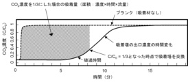
- the switching of adsorption and desorption of the adsorption towers 41a and 41b is preferably performed based on the breakthrough time characteristics of CO 2 gas in the adsorption tower 41, as shown in FIG.
- the concentration of CO 2 (C/C 0 ) at the outlet of the adsorption tower performing adsorption is approximately 1/3 (however, if it is within the range of 1/4 or more and 1/2 or less) It is preferable to switch between adsorption and desorption in the adsorption towers 41a and 41b by switching the valves 51 to 53 at the timing when the adsorption towers 41a and 41b reach the desired timing. By switching between adsorption and desorption at this timing, adsorption and desorption efficiency can be maximized.
- C 0 represents the maximum adsorption amount of CO 2 in the adsorption tower.
- the pressure during CO 2 adsorption in the adsorption towers 41a and 41b is adjusted to 5 MPa or more and 45 MPa or less.
- the amount of CO 2 adsorbed by the CO 2 adsorbent depends on the pressure, and increases as the pressure increases. However, at high pressure, it is difficult to increase the size of the adsorption tower, so it is preferable to adjust the pressure to 5 MPa or more and 45 MPa or less.
- the value of 45 MPa is the maximum filling pressure of a 250 L container made of chromium-molybdenum steel with a wall thickness of 22 mm, and it is not easy to manufacture an adsorption tower having pressure resistance higher than this value.
- the gas discharged from the second CO 2 separation equipment 2 includes a treated gas controlled to have a low concentration of CO 2 (low concentration CO 2 gas) as shown below, and a treated gas with a higher concentration of CO 2 (low concentration CO 2 gas). It is divided into high concentration CO 2 gas (high concentration CO 2 gas).
- the low concentration CO 2 gas (processing gas) is discharged by the low concentration CO 2 gas exhaust equipment 60 .
- the high concentration CO 2 gas is refluxed to the first CO 2 separation equipment by the gas reflux equipment 70 (high concentration CO 2 gas discharge device 45, reflux piping 16).
- the low concentration CO 2 gas exhaust equipment 60 and the gas reflux equipment 70 high concentration CO 2 gas exhaust device 45, reflux pipe 16
- the low-concentration CO 2 gas exhaust equipment 60 is a device that discharges the low-concentration CO 2 gas after CO 2 has been adsorbed by the adsorption separation device 80 . That is, the low concentration CO 2 gas discharge equipment 60 discharges gas containing CO 2 at a concentration lower than the concentration of CO 2 in the gas supplied from the pipe 14 to the adsorption separation device 80 (low concentration CO 2 gas). .
- the low concentration CO 2 gas exhaust equipment 60 is, for example, a device (processing gas exhaust device) including a flow rate regulator 46 and piping 15.
- the low concentration CO 2 gas discharged from the second CO 2 separation facility 2 is discharged from the CO 2 separation system 101 via the valve 53 and the low concentration CO 2 gas discharge facility 60 .
- the flow rate regulator 46 adjusts the flow rate so that the pressure of the gas in the pipe 15 is slightly lower than the pressure during CO 2 adsorption in the adsorption towers 41a and 41b, and adjusts the pressure in the adsorption tower 41 and gas retention. Secure time.
- the processed gas discharged from the low-concentration CO2 gas exhaust equipment 60 has a low concentration of CO2 , so the gas will not freeze and cause clogging even in polar regions, and will be delivered to the consumption area via pipelines etc. Is possible. Additionally, if CO 2 is removed, it becomes possible to transport more natural gas in the same pipeline, reducing natural gas transportation costs.
- the CO 2 concentration in the gas introduced into the adsorption towers 41a and 41b (that is, the gas supplied via the pipe 14) is adjusted to 2 mol% or more and 40 mol% or less by the first CO 2 concentration separation equipment. It is preferable that It is preferable that the concentration of CO 2 in the low concentration CO 2 gas discharged from the low concentration CO 2 gas exhaust equipment 60 is adjusted to 0.5 mol % or more and 10 mol % or less.
- the CO 2 concentration in the gas introduced into the adsorption towers 41a and 41b is more preferably adjusted to 10 mol% or more and 40 mol% or less by the first CO 2 concentration separation equipment.
- the concentration of CO 2 in the low concentration CO 2 gas discharged from the low concentration CO 2 gas exhaust equipment 60 is adjusted to 2 mol % or more and 10 mol % or less.
- the concentration of CO 2 in the gas introduced into the adsorption towers 41a and 41b and the concentration of CO 2 in the low concentration CO 2 gas discharged from the low concentration CO 2 gas discharge equipment 60 are adjusted to concentrations within this range. By doing so, a large reduction in greenhouse gas emissions can be achieved.
- the CO 2 concentration in the gas introduced into the adsorption towers 41a and 41b is more preferably adjusted to 2 mol% or more and 10 mol% or less by the first CO 2 concentration separation equipment.
- the concentration of CO 2 in the low concentration CO 2 gas discharged from the low concentration CO 2 gas exhaust equipment 60 is more preferably adjusted to 0 mol% or more and 2 mol% or less, but 0.5 mol% or more and 2 mol% or less. Sometimes it becomes.
- the concentration of CO 2 in the gas introduced into the adsorption towers 41a and 41b and the concentration of CO 2 in the low concentration CO 2 gas discharged from the low concentration CO 2 gas discharge equipment 60 are adjusted to concentrations within this range. This will help prevent pipeline corrosion.
- the gas reflux equipment 70 includes the high concentration CO 2 gas discharge device 45 and the reflux pipe 16, as described above.
- the reflux pipe 16 is a pipe generally used for transporting gas.
- the gas reflux equipment 70 functions as an element that returns at least a portion of the gas discharged from the high concentration CO 2 gas discharge device 45 to the first CO 2 separation equipment 1 via the reflux pipe 16.
- the high concentration CO 2 gas discharge device 45 is a device that desorbs and discharges CO 2 from the adsorption separation device 80 (adsorption tower 41) after adsorbing CO 2 . That is, the high-concentration CO 2 gas exhaust device 45 generates gas containing CO 2 at a higher concentration than the concentration of CO 2 in the low-concentration CO 2 gas discharged by the low-concentration CO 2 gas exhaust equipment 60 (high-concentration CO 2 gas).
- a pump that desorbs CO 2 from the adsorption separation device 80 by reduced pressure is illustrated as the high-concentration CO 2 gas discharge device 45.
- the high concentration CO 2 gas is refluxed to the first CO 2 separation equipment 1 through the valve 52 and the gas reflux equipment 70 (the high concentration CO 2 gas discharge device 45 and the reflux pipe 16), and is reprocessed (i.e. cryogenic separation treatment). ) is carried out.
- the concentration of CO 2 in the high concentration CO 2 gas is preferably 50 mol% or more and 99 mol% or less, more preferably 50 mol% or more and 90 mol% or less. If the concentration of CO 2 in the high concentration CO 2 gas is adjusted within this range, the efficiency of the CO 2 separation system will be improved.
- the concentration of CO 2 in the high concentration CO 2 gas can be adjusted by the temperature and pressure during CO 2 adsorption in the adsorption towers 41a and 41b, and the filling rate of rubber, which is the CO 2 adsorbent.
- refluxing the highly concentrated CO 2 gas to the first CO 2 separation equipment 1 is extremely important in order to increase the recovery rate of methane. This is because, in the present invention, rubber in the form of pellets, powder, and particulates is used as the CO 2 adsorbent, and high-pressure gaseous methane exists around these CO 2 adsorbents. . Therefore, when high-concentration CO 2 gas is discharged, methane is also discharged, and if this is disposed of, it will lead to methane loss. However, since the methane contained in this highly concentrated CO 2 gas is refluxed to the first CO 2 separation equipment 1 and then returned to the second CO 2 separation equipment 2, there is no substantial loss of methane. be.
- the adsorption tower 41 has a long flow path 42 inside the adsorption tower 41 to ensure residence time and reduce the space in the flow path 42, as shown in FIG. It is preferable that rubber, which is a CO 2 adsorbent, is placed at 43 .
- a crosslinked product of PDMS PolyDiMethylSiloxane
- a method using a radical crosslinking agent or a method of crosslinking a plurality of vinyl groups in the molecules of both PDMS by hydrosilation are preferably used.
- the latter method typically utilizes platinum catalysts.
- recovered rubber such as waste tires as the rubber for the CO 2 adsorbent.
- the glass transition temperature of the rubber is preferably -150°C or more and -10°C or less
- the SP value at room temperature is preferably 7.0 (cal/cm 3 ) 0.5 or more and 10.0 (cal/cm 3 ) 0.5 or less.
- the elastic modulus at 25° C. is preferably 0.03 MPa or more and 8 MPa or less. Rubber under these conditions has a high CO 2 adsorption amount and adsorption/desorption efficiency.
- FIG. 7 shows the relationship between absolute pressure and CO 2 adsorption amount at a temperature of 245 K when PDMS rubber is used.
- This rubber has a glass transition temperature of -150°C, an SP value of 7.5 (cal/cm 3 ) 0.5 at room temperature, and an elastic modulus of about 4 MPa at 25°C. It can be seen that it has good CO 2 adsorption properties.
- Rubbers with an SP value of 10.5 (cal/cm 3 ) 0.5 or less at room temperature are generally hydrophobic, but some rubbers tend to adsorb water.
- by making the rubber hydrophobic it becomes possible to absorb a large amount of CO 2 at sub-zero temperatures.
- water tends to adsorb to the rubber interface and voids, and even a small amount of water can easily reduce adsorption performance.
- the contact angle of water on the surface of the CO 2 adsorbent may be 80° or more and 150° or less. It is important that the SP value of rubber at room temperature be close to the SP value of CO2 , but it is known that the SP value of CO2 increases as the temperature decreases. The SP value of rubber also increases with decreasing temperature, but the increase in SP value of PDMS rubber is somewhat slow compared to the increase in SP of CO2 . Therefore, in the range of -20°C to -40°C, a rubber with a slightly larger SP value than PDMS rubber is desirable. Examples of such rubber include PDMS rubber in which the methyl group in the molecule is replaced with a phenyl group or the like.
- the rubber by making the rubber into powder or fine particles, the surface area increases, making it possible to quickly absorb CO 2 .
- rubber such as PDMS that is powdered or made into fine particles with a size of 500 ⁇ m or less, for example, can be preferably used.
- pellet-shaped rubber can be preferably used because it is easy to handle and replace. Furthermore, adsorption of CO 2 into pellet-shaped rubber begins near the surface layer of the rubber, but the adsorption rate becomes considerably slow at a depth of 2.5 mm or more from the surface layer. Therefore, from the viewpoint of CO 2 adsorption speed, the thickness of the rubber pellets is preferably 5 mm or less.
- the lower limit of the thickness of the rubber is not particularly limited, but from the viewpoint of ease of handling and stability of quality, it is preferably 0.1 mm or more. Therefore, when the rubber is made into pellets, the thickness thereof is preferably 0.1 mm or more and 5 mm or less. Desorption of CO 2 using rubber can be achieved by reducing the pressure, and because there is no need for heating, it is characterized by low energy consumption.
- the rubber be packed in a mesh or porous bag and provided in the adsorption tower 41.
- the adsorption separation device 80 may include a first adsorption tower group consisting of a plurality of adsorption towers 41a and a second adsorption tower group consisting of a plurality of adsorption towers 41b.
- a first adsorption tower group for example, a plurality of adsorption towers 41a are arranged in series.
- a second adsorption tower group for example, a plurality of adsorption towers 41b are arranged in series.
- FIG. 5 illustrates an adsorption tower group (first adsorption tower group, second adsorption tower group) in which three adsorption towers 41_1, 41_2, and 41_3 are arranged in series.
- each adsorption tower group first adsorption tower group, second adsorption tower group
- the first adsorption tower group and the second adsorption tower group are a pair of adsorption tower groups having the same configuration. That is, it is preferable that the first adsorption tower group and the second adsorption tower group have the same internal configuration of each adsorption tower, as well as the number of adsorption towers and the arrangement of the adsorption towers.
- rubber is used as the CO 2 adsorbent, and powder or fine particles are preferably used to improve adsorption amount and adsorption efficiency.
- desired gases such as methane are likely to be trapped there. That is, a problem arises in that the recovery rate of the desired gas tends to decrease.
- a gas reflux equipment 70 including a high concentration CO 2 gas discharge device 45 and a reflux pipe 16 is provided, and the gas containing high concentration CO 2 is transferred to the first CO 2 separation equipment 1. Reprocessing is carried out using a cryogenic separation device to increase the recovery rate of the desired gas. Through this treatment, the recovery rate of the desired gas becomes 90% or more.
- the gas reflux equipment 70 include the reflux pipe 16.
- a pump is used as the high concentration CO 2 gas exhaust device 45, but various types can be used as the high concentration CO 2 gas exhaust device 45.
- a compressor a type of pump
- the gas containing high concentration CO 2 can be pressurized and forcibly sent to the first CO 2 separation equipment 1. Can be done.
- a pump is used as the high-concentration CO 2 gas discharge device 45
- the temperature of the adsorption tower increases by sending the heat medium to the second CO 2 separation equipment 2, and as a result, the desorbed CO 2 is transferred to the first CO 2 gas discharge device 45. 2 is sent to separation equipment 1.
- the gas reflux equipment 70 may include, for example, a pump (compressor), a heating device, or both a pump (compressor) and a heating device.
- the gas can also be refluxed by applying heat to the adsorption separation device 80 using a heating device.
- a compressor capable of reducing the pressure inside the adsorption tower of the second CO 2 separation equipment 2 is preferably used.
- a CO 2 separation system using rubber as an adsorbent is capable of separating CO 2 at a high concentration, and has the feature that the energy required for the separation is less than that of a chemical absorption method using an amine solvent. Furthermore, the recovery rate of the desired gas is high due to the reflux of the gas containing the high concentration of CO2 .
- CO 2 can be efficiently separated with low energy, and the CO 2 concentration is 2% or less. It was confirmed that methane gas could be efficiently supplied. It can be said that the CO 2 separation system of the present invention makes it possible to transport natural gas produced in polar regions by pipeline at low cost. Since biogas also generally contains high concentrations of CO 2 , the CO 2 separation system of the present invention is also effective in treating biogas.
- a mixed gas of CO 2 and N 2 was used as the gas to be treated, and CO 2 was separated from the gas to be treated by the following CO 2 separation system.
- the CO 2 separation system according to the example was composed of the following elements. The following elements are connected through piping.
- Gas cylinders to be treated (CO 2 gas cylinder and N 2 gas cylinder)
- a gas flow meter that adjusts the flow rate of a CO 2 gas cylinder.
- a gas flow meter that adjusts the flow rate of an N 2 gas cylinder.
- a first cooling device that removes some CO 2 and moisture contained as impurities in the gas to be treated.
- a second cooling device that controls the column temperature
- a pressure gauge that measures the pressure in the column and CO 2 recovery vessel
- a column flow meter that controls the column pressure
- a gas chromatograph that measures the concentration of components in the gas discharged from the column Adsorbed on the rubber
- a CO 2 recovery container that recovers CO 2
- a third cooling device that controls the temperature of the CO 2 recovery container
- the above-mentioned first cooling device, third cooling device, and CO 2 recovery container are connected to the first CO 2 separation equipment (
- the above-mentioned column is an example of the second CO 2 separation equipment.
- a CO 2 adsorption test and a CO 2 desorption/recovery test were conducted.
- the piping connection after the column differs between the CO 2 adsorption test and the CO 2 desorption recovery test, and is switched by a valve installed in the piping immediately after the column.
- the column is connected to a gas chromatograph via a flow meter that controls column pressure, and during CO 2 desorption and recovery, it is connected to a CO 2 recovery container.
- the pressure of the gas to be treated was regulated with a pressure gauge on the secondary side of the regulator.
- the gas to be treated passed through a first cooling device that removed moisture, and the gas after moisture removal was supplied to the column.
- the amount of CO 2 adsorption is determined at the outlet of the adsorption tower where the adsorption and desorption efficiency can be maximized in the characteristic diagram (breakthrough time characteristics of CO 2 gas) showing the adsorption and desorption characteristics of CO 2 using rubber in Figure 6.
- Example 1 KMP-602 manufactured by Shin-Etsu Chemical Co., Ltd. was used as the CO 2 adsorbent.
- the gases to be treated were 20 mol% CO 2 and 80 mol% N 2 .
- the column pressure was 6 MPa, and the column temperature was -30°C. Specifically, first, the column temperature is maintained at -30°C with the second cooling device, only N2 is flowed into the column, and the flow rate of the column flow meter that controls the column pressure is set to zero, thereby increasing the column pressure to 6 MPa. The pressure was increased.
- the gas flow rates connected to the CO 2 gas cylinder and the N 2 gas cylinder are adjusted to 40 sccm and 120 sccm, respectively, and the mixed gas to be treated flows into the column, while at the same time controlling the column pressure.
- the CO 2 adsorption test was started by adjusting the flow rate of the column flowmeter to 200 sccm, and the CO 2 concentration was measured for a predetermined time using a chromatograph, and the amount of CO 2 adsorption was calculated.
- a pump more specifically a compressor
- the high-concentration CO 2 gas discharged from the column is cryogenically cooled. It is desirable to force the transfer to a separation device.
- the amount of CO2 recovered is 1 kg or less, it is not possible to pressurize with a compressor and move the gas stably, so in this example, we realized pressure-driven mass transfer (gas transfer) similar to that using a compressor. In order to do this, the temperature of the CO 2 adsorption tower is raised to reflux the CO 2 to the cryogenic separator.
- FIG. 8 is a breakthrough curve in Example 1.
- the amount of CO 2 adsorbed was 1.8 g from the area of the shaded area in FIG. 8, and the breakthrough time was 23 minutes against the target value of 5 to 60 minutes, indicating good adsorption characteristics.
- Table 1 shows the results of the CO 2 adsorption test and CO 2 desorption recovery test.
- the pressure of the column and recovery container during CO 2 desorption and recovery was 2.9 MPa, the amount of CO 2 desorption and recovery was 1.3 g, and the recovery rate was 72 mol%, so a sufficiently high concentration of CO 2 was recovered. It was shown that Furthermore, since CO 2 liquefies at ⁇ 40° C. and 1 MPa, the desorbed and recovered CO 2 is considered to be liquefied CO 2 .
- Example 1 exhibited good adsorption characteristics with a breakthrough time of 23 minutes and an adsorption amount of 1.8 g under conditions where the adsorption pressure was 6 MPa and the CO 2 concentration of the gas to be treated was 20 mol %. Furthermore, the temperature during desorption and recovery was -40°C, and the liquefied CO 2 recovery rate was 72%, indicating good desorption and recovery characteristics.
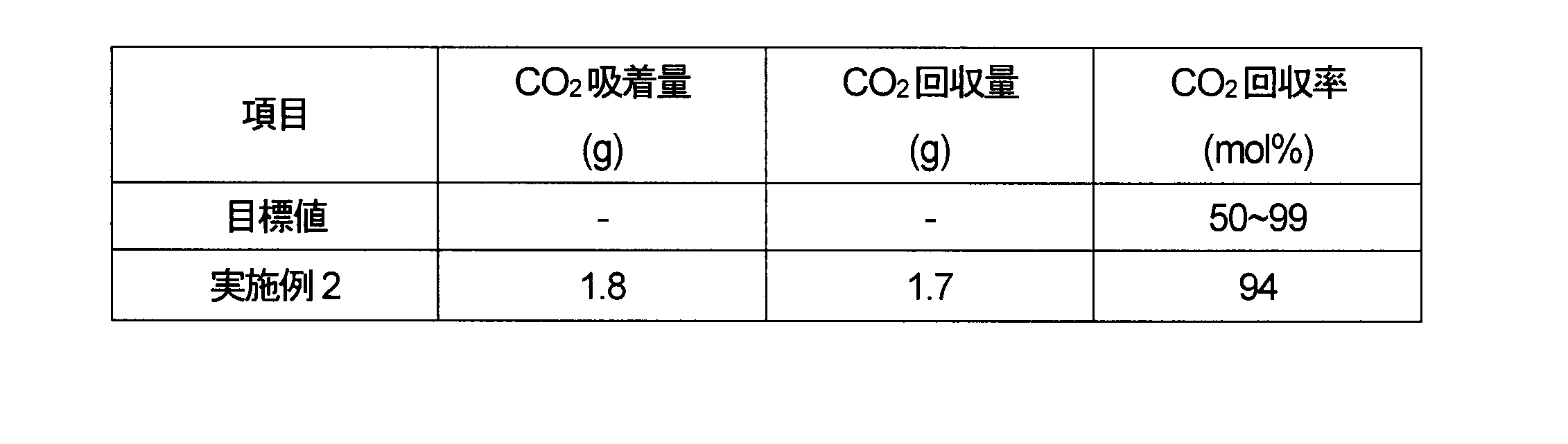
- Example 2 A pulverized product of K-125 manufactured by Togawa Rubber Co., Ltd. was used as the CO 2 adsorbent. A desorption experiment of 1.8 g of adsorbed CO 2 was conducted using the same apparatus as in Example 1. Table 2 shows the CO 2 adsorption test and CO 2 desorption recovery test and results. The pressure of the column and recovery container during CO 2 desorption and recovery was 1.0 MPa, the amount of CO 2 desorption and recovery was 1.7 g, and the recovery rate was 94 mol%, so a very high concentration of CO 2 was recovered. It was shown that
- the present invention it becomes possible to efficiently remove CO 2 from natural gas, biogas, etc. that contain a large amount of CO 2 .
- This makes it possible, for example, to process natural gas containing a high concentration of CO 2 at low cost and supply it through pipelines at low cost.
- the present invention enables the effective use of gas, which has been difficult to utilize up to now, and is believed to greatly contribute to the development of industry and society.
- a CO 2 separation system that separates CO 2 from natural gas containing a high concentration of CO 2 of 30% or more and supplies CO 2 at 2% or less.
- Natural gas containing a large amount of CO 2 has the problem of freezing in low-temperature regions such as polar regions. Also, natural gas containing more than 2% CO2 corrodes pipelines.
- natural gas containing a high concentration of CO 2 can be efficiently processed at low cost and transported by pipeline at low cost.
Landscapes
- Engineering & Computer Science (AREA)
- Chemical & Material Sciences (AREA)
- Chemical Kinetics & Catalysis (AREA)
- Mechanical Engineering (AREA)
- Oil, Petroleum & Natural Gas (AREA)
- General Chemical & Material Sciences (AREA)
- Physics & Mathematics (AREA)
- Thermal Sciences (AREA)
- General Engineering & Computer Science (AREA)
- Organic Chemistry (AREA)
- Analytical Chemistry (AREA)
- Inorganic Chemistry (AREA)
- Separation Of Gases By Adsorption (AREA)
Abstract
Description
(1)CO2濃度が2%以下の場合
この場合は、必ずしもCO2を分離する必要がない。CO2濃度が2%以下であれば、パイプラインの腐食の影響が少ないからである。但し、液化天然ガス(LNG)を生産する場合は、深冷分離法の適用の前にAGR(Acid Gas Removal)プロセスが適用される。
(2)CO2濃度が30%前後の場合
古い設備では、溶融炭酸カリウムが用いられていたが、アミン溶媒を用いたAGRプロセスに置き換わりつつある。アミン溶媒は、熱により吸着材が再生でき、設備のメンテナンスが容易である。一方、溶融炭酸カリウムでは、鋼材の腐食がしばしば問題となる。
(3)CO2濃度が30~60%の場合
吸着材(吸収剤)として、プロピレンカーボネート(PC)などの有機溶媒が用いられる。CO2濃度が高いとアミン溶媒の再生に大きな熱エネルギーが必要になるため、AGRプロセスは利用できなくなる。
(4)CO2濃度が70%以上の場合
現状、開発に難儀していて、新しいCO2分離技術への期待が大きい。
なお、有機溶媒を吸着材(吸収剤)として用いてCO2を回収する方法は、混合ガスを高圧のマイクロバブルにして溶かし込む必要があるのでエネルギー損失が大きく、また、有機溶媒の一部が揮発するため、揮発した有機溶媒の回収コストも必要となるという問題がある。
(構成1)
第1のCO2分離設備と、第2のCO2分離設備と、第1の配管と、低濃度CO2ガス排出設備と、第2の配管と高濃度CO2ガス排出装置とを具備するガス還流設備とを有し、前記第1のCO2分離設備は、被処理ガスから深冷分離処理によりCO2を分離する深冷分離装置からなり、前記第1の配管は、前記第1のCO2分離設備から排出されるガスを前記第2のCO2分離設備に供給し、前記第2のCO2分離設備は、ゴムをCO2吸着材として備える吸着分離装置を備え、前記低濃度CO2ガス排出設備は、前記第2のCO2分離設備から、低い濃度のCO2を含むガスを排出し、前記高濃度CO2ガス排出装置は、前記第2のCO2分離設備から、前記低い濃度より高い濃度のCO2を含んだガスを排出し、前記ガス還流設備においては、前記高濃度CO2ガス排出装置から排出されるガスの少なくとも一部を前記第2の配管を介して前記第1のCO2分離設備に戻し、前記第1のCO2分離設備は、前記ガス還流設備により戻されたガスから、CO2を分離する深冷分離処理を行うCO2分離システム。
(構成2)
前記第2のCO2分離設備は、1台以上の吸着塔からなる第1の吸着塔群と1台以上の吸着塔からなる第2の吸着塔群を有し、前記吸着塔は、内部にガスを滞留させつつ流す流路、および、前記CO2吸着材を有し、当該CO2分離システムは、前記流路と前記CO2吸着材とを冷却することが可能な冷却手段をさらに具備する、構成1記載のCO2分離システム。
(構成3)
前記第1の吸着塔群と前記第2の吸着塔群は、同じ構成で対をなす吸着塔群である、構成2記載のCO2分離システム。
(構成4)
前記第1の吸着塔群および前記第2の吸着塔群を構成する吸着塔の少なくとも一部は、前記第1の吸着塔群および前記第2の吸着塔群の中で直列に配置される、構成2記載のCO2分離システム。
(構成5)
前記吸着塔1台当たりのガスの破過時間は5分以上60分以下である、構成2記載のCO2分離システム。
(構成6)
前記第1の吸着塔群および前記第2の吸着塔群に導入されるガス中のCO2濃度は10mol%以上40mol%以下に調整され、前記第1の吸着塔群および前記第2の吸着塔群から排出されるガス中のCO2濃度は2mol%以上10mol%以下に調整された、構成2から5の何れか1項に記載のCO2分離システム。
(構成7)
前記第1の吸着塔群および前記第2の吸着塔群に導入されるガス中のCO2濃度は5mol%以上10mol%以下に調整され、前記第1の吸着塔群および前記第2の吸着塔群から排出されるガス中のCO2濃度は0mol%以上2mol%以下に調整された、構成2から5の何れか1項に記載のCO2分離システム。
(構成8)
前記吸着塔の吸着圧力が5MPa以上45MPa以下に調整された、構成2から7の何れか1項に記載のCO2分離システム。
(構成9)
前記冷却の温度は-50℃以上0℃以下である、構成2記載のCO2分離システム。
(構成10)
前記高い濃度のCO2の濃度は50mol%以上99mol%以下である、構成1記載のCO2分離システム。
(構成11)
前記ゴムは、ペレット状、粉体状および微粒子状からなる群から選ばれる1以上の状態で備えられる、構成1から10の何れか1項に記載のCO2分離システム。
(構成12)
前記ゴムは、網目状または多孔の袋に詰めて備えられる、構成11記載のCO2分離システム。
(構成13)
前記深冷分離装置は、供給されたガスを圧縮する圧縮装置と、前記圧縮装置を介して導入されたガスを冷却する冷却装置と、前記冷却を受けて液化したCO2を排出する装置を備える、構成1記載のCO2分離システム。
(構成14)
前記被処理ガスが、ガスを減圧して液状CO2を分離する減圧設備を介して前記深冷分離装置に導入される、構成1記載のCO2分離システム。
(構成15)
前記被処理ガスが、脱水を行う脱水設備を介して前記深冷分離装置に導入される、構成1から14の何れか1項に記載のCO2分離システム。
被処理ガスは、例えば、減圧設備4および脱水設備5を介して第1のCO2分離設備1に供給される。まず、被処理ガスが配管11を介して減圧設備4に供給される。次に、減圧設備4を通過した被処理ガスが配管12を介して脱水設備5に供給される。そして、脱水設備5を通過した被処理ガスが配管13を介して第1のCO2分離設備1に供給される。
第1のCO2分離設備1は、配管14を通じて第2の分離設備2に繋がれている。第2の分離設備2で処理されたガスの一部を第1の分離設備1に還流するための還流配管16が、第2の分離設備2と第1の分離設備1とに接続されている。さらに、第1のCO2分離設備1は、当該第1のCO2分離設備1で処理されて生成された液状のCO2およびその他の凝縮性ガスの液体を排出する排出配管17を備える。
減圧設備4は、60MPa以上の高い圧力の被処理ガス(例えば地中深くから湧き上がる高圧ガスなど)を減圧することを目的に備えられる設備であり、例えばチョークおよび温度調製装置からなる。被処理ガスが、例えば初期圧力が120MPa近くあり、水を含んでいる場合には、減圧により急速に冷却すると、メタンハイドレードが形成されてしまうため、これを防止するために温度調製装置が必要となる。通常の減圧操作では、温度を室温以上に保ちながら、例えば、120MPaから60MPa、15MPa、3MPaなどと段階的に減圧することが多い。なお、減圧設備4は、被処理ガスがCO2を大量に含んでいる場合、適度な減圧により、液状のCO2が生成されるので、CO2を排出する配管を備えていても良い。また減圧設備4では、冷却により水やコンデンセート(液状の炭化水素)が生成される場合があり、CO2を排出する配管からは水やコンデンセートも排出できる。被処理ガスがコンデンセートを含む天然ガスの場合は、有価物であるコンデンセートを排出させた方が望ましい。
脱水設備5は、被処理ガス中の水分の除去を行うことを目的に備えられる設備である。脱水設備5は、被処理ガス中の水分の除去する除去剤を有する。水の除去剤としては、モレキュラーシーブ(ゼオライト、登録商標)、シリカゲル、活性炭、活性アルミナ、エチレングリコール誘導体などが利用できる。特に、-40℃程度の露点が実現できるシリカゲルや活性アルミナを用いた脱水設備5が好適に利用できる。被処理ガス中の水は、温度をさげることでほぼ液状になるが、脱水設備5では、室温付近でも凝集しない気相中の水分を除去するために利用される。脱水設備5は、図示はしていないが、水の除去剤を再生するために、ヒーターと脱着蒸気の冷却機とが備えられえている。また、脱水設備5は、ハイドレードの形成を防ぐために0℃以上で運転することが望ましい。また、連続運転の場合は複数の吸着塔を備えた脱水設備5となる。例えば、脱水設備5は、被処理ガスを天然ガスとしたときに備えられる。
第1のCO2分離設備1は、被処理ガスからCO2を分離するための深冷分離処理を行う装置である。第1のCO2分離設備1は、還流配管16を通じて還流されたガスの少なくとも一部が第1のCO2分離設備1で処理される経路とを有することを除いて、通常使用される深冷分離装置を用いることができる。
図2は、本実施形態の第1のCO2分離設備1の一例に係る構成図である。第1のCO2分離設備1は、図2に示すように、例えば、圧縮装置21、脱水装置22、冷却装置23および液化CO2排出装置24を備える。。
脱水装置22は、圧縮処理後のガスから水分を除去する乾燥ガス化処理(脱水処理)を行う装置である。乾燥ガス化処理の方法としては、シリカゲルやゼオライトを用いる方法が優れている。ここで、乾燥ガス化処理された乾燥ガスに含まれる水の量は、10ppm以下に管理されていることが好ましい。なお、シリカゲルでの脱水は、高温では吸着量が落ちるため、30℃以下で行うことが望ましい。なお、脱水設備5で十分な脱水が行われている場合には、脱水装置22は省略することもできる。
乾燥ガス化処理されたガスは、配管32を介して冷却装置23に供給される。ここで、冷却装置23としては、特に限定はないが、例えばCO2を冷媒として蒸気圧縮式冷凍機を用い、その冷熱を利用することができる。また、CO2の固化が起こらない範囲で、断熱膨張による冷却も併用できる。
冷却装置23では、供給されたガスを-40℃以上0℃以下に冷却する。冷却装置23に供給されるガスは既に脱水されており、ハイドレートは形成されないので、冷却装置23の温度は、CO2の固化が起こらない範囲で、低温であることが望ましい。また、圧力は、10MPa以上50MPa以下であるが、耐圧容器の安全性が確保できる範囲で高圧であることが望ましい。冷却されたガスは配管33を介して液化CO2排出装置24に運ばれ、冷却によって生成された液状のCO2などの液状物は排出配管17を通じて排出される。
液化CO2排出装置24は、液体のCO2を排出するポンプであり、冷却装置23と同様に冷却設備3で冷却しておく必要がある。
図3は、本実施形態に係る第2のCO2分離設備2の一例に係る構成図である。第2のCO2分離設備2は、第1のCO2分離設備1における深冷分離処理で分離しきれなかったCO2を除去するための設備である。図3に示される通り、第2のCO2分離設備2は、ゴムを吸着材として備える吸着分離装置80を具備する。
第1のCO2分離設備1で処理されたガスは、配管14およびバルブ51を介して吸着塔41aまたは吸着塔41bの何れかに切り替えて導入される。吸着塔41aおよび吸着塔41bは、バルブ52と高濃度CO2ガス排出装置45とを介して還流配管16に繋がれる。また、吸着塔41aおよび吸着塔41bは、バルブ53と流量調整器46とを介して配管15に繋がれる。バルブ51、52および53の切り替えによって、吸着塔41aおよび吸着塔41bの一方をCO2吸着に使用し、他方をCO2脱着に使用する。すなわち、CO2吸着とCO2脱着とが並行して行われる。吸着塔41aにおけるCO2吸着とCO2脱着とは交互に実行され、吸着塔41bにおけるCO2吸着とCO2脱着とは交互に実行される。
ここで、吸着および脱着の制御は圧力で行う。吸着塔41aおよび吸着塔41bは、断熱仕様とするが、予備冷却と低温での温度維持とのために、冷却設備3を用いる。ここで、吸着時の吸着塔41a,41b内の温度は-50℃以上0℃以下が好ましく、-40℃以上-20℃以下がより好ましい。冷却設備3は、内部にガスを滞留させつつ流す流路(後述する流路42)とCO2吸着材とを冷却することが可能な冷却手段の例示である。
吸着時における吸着搭41a,41b内をこの範囲の温度に制御することにより、脱着時のCO2の固化を防ぐことができ、分離効率が向上するという効果が得られる。なお、第2のCO2分離設備の吸着塔41の温度は、第1のCO2分離設備(深冷分離装置)の温度より低い方が望ましい。これは、第2のCO2分離設備では、第1のCO2分離設備と比較して、ガス中のCO2濃度が下がっており、CO2の固化が起こりにくく、低温である方が吸着塔41におけるCO2分離効率がより高いためである。
低濃度CO2ガス排出設備60は、吸着分離装置80によりCO2が吸着された後の低濃度CO2ガスを排出する装置である。すなわち、低濃度CO2ガス排出設備60は、配管14から吸着分離装置80に供給されたガス中のCO2の濃度よりも低い濃度でCO2を含むガス(低濃度CO2ガス)を排出する。
吸着塔41aおよび41bに導入されるガス中のCO2濃度は、第1のCO2濃分離設備によって、10mol%以上40mol%以下に調整されることがより好ましい。低濃度CO2ガス排出設備60から排出される低濃度CO2ガス中のCO2の濃度は、2mol%以上10mol%以下に調整されていることがより好ましい。吸着塔41aおよび41bに導入されるガス中のCO2濃度と、低濃度CO2ガス排出設備60から排出される低濃度CO2ガス中のCO2の濃度とが、この範囲の濃度に調整されていると、温室効果ガスの大きな削減効果が得られる。
または、吸着塔41aおよび41bに導入されるガス中のCO2濃度は、第1のCO2濃分離設備によって、2mol%以上10mol%以下に調整されることがより好ましい。低濃度CO2ガス排出設備60から排出される低濃度CO2ガス中のCO2の濃度は、0mol%以上2mol%以下に調整されていることがより好ましいが、0.5mol%以上2mol%以下になる場合もある。吸着塔41aおよび41bに導入されるガス中のCO2濃度と、低濃度CO2ガス排出設備60から排出される低濃度CO2ガス中のCO2の濃度とが、この範囲の濃度に調整されていると、パイプラインの腐食防止効果が得られる。
ガス還流設備70は、上述した通り、高濃度CO2ガス排出装置45と還流配管16とを含む。なお、還流配管16には、ガスの搬送に一般的に用いられる配管が使用される。具体的には、ガス還流設備70は、高濃度CO2ガス排出装置45から排出されるガスの少なくとも一部を還流配管16を介して第1のCO2分離設備1に戻す要素として機能する。
ここで高濃度CO2ガスを第1のCO2分離設備1に還流することは、メタンの回収率を上げるために極めて重要となる。というのも、本発明では、ペレット状、粉体状および微粒子状のゴムをCO2吸着材として用いており、これらのCO2吸着材の周りには高圧のガス状のメタンが存在している。従って、高濃度CO2ガスの排出時にはメタンも一緒に排出されてしまい、これを廃棄するとメタンのロスにつながる。しかし、この高濃度CO2ガスに含まれるメタンは、第1のCO2分離設備1に還流され、再び第2のCO2分離設備2に戻ってくるため、実質的なメタンのロスがなくなるのである。
PDMSゴムを用いたときの温度245Kにおける絶対圧とCO2吸着量の関係を図7に示す。このゴムのガラス転移温度は-150℃、室温でのSP値は7.5(cal/cm3)0.5、そして25℃での弾性率は約4MPaである。良好なCO2吸着特性を有していることがわかる。
室温でのゴムのSP値は、CO2のSP値と近いことが重要であるが、CO2のSP値は温度の低下とともに大きくなることが知られている。ゴムのSP値も温度の低下とともに増加するが、PDMSゴムのSP値の増加はCO2のSPの増加と比較してやや低調である。このため、-20℃から-40℃の範囲では、PDMSゴムよりややSP値が大きなゴムが望ましい。このようなゴムとして、PDMSゴムの分子内のメチル基をフェニル基などで置換したものが挙げられる。
CO2の吸着速度、脱着速度の観点から、例えば500μm以下のサイズに粉末化、微粒子化したPDMSなどのゴムを好んで用いることができる。
さらに、ペレット状のゴムへのCO2の吸着は、ゴム表層近傍部から始まるが、表層から2.5mm以上の深さになると、吸着速度がかなり遅くなる。このため、CO2の吸着速度の観点から、ペレット状のゴムの厚さは5mm以下が好ましい。ゴムの厚さの下限は特に限定はないが、取り扱いの容易さや品質の安定性から0.1mm以上が好ましい。したがって、ゴムをペレット状とするときはその厚さは0.1mm以上5mm以下が好ましい。
ゴムを用いたCO2の脱着は、減圧することで達成でき、加熱の必要がないことからエネルギーの消費が少ないという特徴をもつ。
この場合、ゴム間の隙間領域が大きく、吸着時の圧力が5MPa以上45MPa以下という高圧下であるため、そこにメタンなどの所望のガスがトラップされやすい。即ち、所望のガスの回収率が下がりやすいという問題が起こる。
この問題を解決するため、本発明では、高濃度CO2ガス排出装置45と還流配管16を含むガス還流設備70を設け、高濃度のCO2を含んだガスを第1のCO2分離設備1である深冷分離装置を用いて再処理を行い、所望のガスの回収率を高めている。この処理により、所望のガスの回収率は90%以上となる。
実施例に係るCO2分離システムは、以下の要素で構成した。以下の各要素は、配管を通して接続されている。
被処理ガスボンベ(CO2ガスボンベおよびN2ガスボンベ)
CO2ガスボンベの流量を調整するガス流量計
N2ガスボンベの流量を調整するガス流量計
被処理ガス中の一部のCO2と不純物として含有される水分を除去する第1冷却装置
CO2吸着材となるゴム(信越化学工業社製KMP-602(真比重0.98、粒子径分布4-60um)または十川ゴム社製K-125の粉砕品(真比重1.20、粒子径分布350-1000um))が充填されたカラム
(カラム体積:22.6cm3、ゴム充填率:76.7%(KMP-602)、77.0(K-125))
カラム温度を制御する第2冷却装置
カラムおよびCO2回収容器の圧力を測定する圧力計
カラム圧力を制御するカラム流量計
カラムから排出されるガス中の成分の濃度を測定するガスクロマトグラフ
ゴムに吸着したCO2を回収するCO2回収容器
CO2回収容器の温度を制御する第3冷却装置
なお、上記の第1冷却装置と第3冷却装置とCO2回収容器とが第1のCO2分離設備(深冷分離装置)の例示であり、上記のカラムが第2のCO2分離設備の例示である。
CO2吸着量は、図6のゴムを用いたCO2の吸着、脱着特性を示す特性図(CO2ガスの破過時間特性)において、吸脱着効率を最大化することができる吸着塔の出口濃度の時間変化がC/C0=1/3となった時点でのCO2吸着量を採用した。CO2吸着量は、図中の斜線部分の面積であり、「吸着量=CO2濃度(C/C0)×時間(C/C0=1/3となった時間)×流量」から算出した。
CO2吸着材として信越化学工業社製KMP-602を用いた。被処理ガスは、CO2を20mol%、N2を80mol%とした。カラム圧力は、6MPa、カラム温度は、-30℃とした。具体的には、まず第2冷却装置でカラム温度を-30℃に保ち、N2のみをカラムに流し込み、カラム圧力を制御するカラム流量計の流速をゼロとすることで、カラム圧力を6MPaまで昇圧させた。
その後、CO2ガスボンベおよびN2ガスボンベに接続されたガス流量計でそれぞれの供給ガス流速を40sccm、120sccmに調節して、これらを混合した被処理ガスを、カラムに流し込むと同時に、カラム圧力を制御するカラム流量計の流速を200sccmに調節することにより、CO2吸着試験を開始し、クロマトグラフで所定時間のCO2濃度を測定し、CO2吸着量を算出した。

CO2吸着材として十川ゴム社製K-125の粉砕品を用い。実施例1と同様な装置を用いて吸着させた1.8gのCO2の脱着実験を行った。表2は、CO2吸着試験とCO2脱着回収試験と結果を示す。CO2脱着回収時のカラム及び回収容器の圧力は、1.0MPaで、CO2脱着回収量は1.7gであり、回収率は94mol%であることから非常に高い濃度のCO2が回収されたことが示された。
CO2を大量に含む天然ガスは、極地等低温地帯では、凍結の問題が起こる。また、2%以上のCO2を含む天然ガスがパイプラインを腐食する。しかし、本発明のCO2分離システムを用いると、高濃度のCO2を含む天然ガスを低コストで効率的に処理して、安価にパイプライン輸送することが可能になる。
2:第2のCO2分離設備
3:冷却設備
4:減圧設備
5:脱水設備
11:配管
12:配管
13:配管
14:配管(第1の配管)
15:配管
16:還流配管(第2の配管)
17:排出配管
21:圧縮装置
22:脱水装置
23:冷却装置
24:液化CO2排出装置
31:配管
32:配管
33:配管
41:吸着塔
41a:吸着塔
41b:吸着塔
41_1:吸着塔
41_2:吸着塔
41_3:吸着塔
42:流路
43:空間
45:高濃度CO2ガス排出装置
46:流量調整器
51:切り替えバルブ
52:切り替えバルブ
53:切り替えバルブ
60:低濃度CO2ガス排出設備
70:ガス還流設備
80:吸着分離装置
101:CO2分離システム
Claims (15)
- 第1のCO2分離設備と、
第2のCO2分離設備と、
第1の配管と、
低濃度CO2ガス排出設備と、
第2の配管と高濃度CO2ガス排出装置とを具備するガス還流設備とを有し、
前記第1のCO2分離設備は、被処理ガスから深冷分離処理によりCO2を分離する深冷分離装置からなり、
前記第1の配管は、前記第1のCO2分離設備から排出されるガスを前記第2のCO2分離設備に供給し、
前記第2のCO2分離設備は、ゴムをCO2吸着材として備える吸着分離装置を備え、
前記低濃度CO2ガス排出設備は、前記第2のCO2分離設備から、低い濃度のCO2を含むガスを排出し、
前記高濃度CO2ガス排出装置は、前記第2のCO2分離設備から、前記低い濃度より高い濃度のCO2を含んだガスを排出し、
前記ガス還流設備においては、前記高濃度CO2ガス排出装置から排出されるガスの少なくとも一部を前記第2の配管を介して前記第1のCO2分離設備に戻し、
前記第1のCO2分離設備は、前記ガス還流設備により戻されたガスから、CO2を分離する深冷分離処理を行う
CO2分離システム。 - 前記吸着分離装置は、1台以上の吸着塔からなる第1の吸着塔群と1台以上の吸着塔からなる第2の吸着塔群とを有し、
前記吸着塔は、内部にガスを滞留させつつ流す流路、および、前記CO2吸着材を有し、
当該CO2分離システムは、前記流路と前記CO2吸着材とを冷却することが可能な冷却手段をさらに具備する
請求項1に記載のCO2分離システム。 - 前記第1の吸着塔群と前記第2の吸着塔群とは、同じ構成で対をなす吸着塔群である、
請求項2に記載のCO2分離システム。 - 前記第1の吸着塔群および前記第2の吸着塔群を構成する吸着塔の少なくとも一部は、前記第1の吸着塔群および前記第2の吸着塔群の中で直列に配置される、
請求項2に記載のCO2分離システム。 - 前記吸着塔1台当たりのガスの破過時間は5分以上60分以下である、請求項2に記載のCO2分離システム。
- 前記第1の吸着塔群および前記第2の吸着塔群に導入されるガス中のCO2濃度は、10mol%以上40mol%以下に調整され、
前記第1の吸着塔群および前記第2の吸着塔群から排出されるガス中のCO2濃度は2mol%以上10mol%以下に調整された、
請求項2から5の何れか1項に記載のCO2分離システム。 - 前記第1の吸着塔群および前記第2の吸着塔群に導入されるガス中のCO2濃度は5mol%以上10mol%以下に調整され、
前記第1の吸着塔群および前記第2の吸着塔群から排出されるガス中のCO2濃度は0mol%以上2mol%以下に調整された、
請求項2から5の何れか1項に記載のCO2分離システム。 - 前記吸着塔の吸着圧力が5MPa以上45MPa以下に調整された、
請求項2から7の何れか1項に記載のCO2分離システム。 - 前記冷却の温度は-50℃以上0℃以下である、
請求項2の記載のCO2分離システム。 - 前記高い濃度のCO2の濃度は50mol%以上99mol%以下である、
請求項1に記載のCO2分離システム。 - 前記ゴムは、ペレット状、粉体状および微粒子状からなる群から選ばれる1以上の状態で備えられる、
請求項1から10の何れか1項に記載のCO2分離システム。 - 前記ゴムは、網目状または多孔の袋に詰めて備えられる、
請求項11の記載のCO2分離システム。 - 前記深冷分離装置は、供給されたガスを圧縮する圧縮装置と、前記圧縮装置を介して導入されたガスを冷却する冷却装置と、前記冷却を受けて液化したCO2を排出する装置とを備える、
請求項1の記載のCO2分離システム。 - 前記被処理ガスが、ガスを減圧して液状CO2を分離する減圧設備を介して前記深冷分離装置に導入される、
請求項1に記載のCO2分離システム。 - 前記被処理ガスが、脱水を行う脱水設備を介して前記深冷分離装置に導入される、
請求項1から14の何れか1項に記載のCO2分離システム。
Priority Applications (2)
| Application Number | Priority Date | Filing Date | Title |
|---|---|---|---|
| EP23846303.8A EP4567356A1 (en) | 2022-07-26 | 2023-07-18 | Co2 separation system |
| JP2024537617A JP7813063B2 (ja) | 2022-07-26 | 2023-07-18 | Co2分離システム |
Applications Claiming Priority (2)
| Application Number | Priority Date | Filing Date | Title |
|---|---|---|---|
| JP2022118342 | 2022-07-26 | ||
| JP2022-118342 | 2022-07-26 |
Publications (1)
| Publication Number | Publication Date |
|---|---|
| WO2024024572A1 true WO2024024572A1 (ja) | 2024-02-01 |
Family
ID=89706303
Family Applications (1)
| Application Number | Title | Priority Date | Filing Date |
|---|---|---|---|
| PCT/JP2023/026275 Ceased WO2024024572A1 (ja) | 2022-07-26 | 2023-07-18 | Co2分離システム |
Country Status (3)
| Country | Link |
|---|---|
| EP (1) | EP4567356A1 (ja) |
| JP (1) | JP7813063B2 (ja) |
| WO (1) | WO2024024572A1 (ja) |
Cited By (3)
| Publication number | Priority date | Publication date | Assignee | Title |
|---|---|---|---|---|
| JP2025155787A (ja) * | 2024-03-28 | 2025-10-14 | 本田技研工業株式会社 | 二酸化炭素回収装置 |
| WO2026088725A1 (ja) * | 2024-10-22 | 2026-04-30 | 国立研究開発法人物質・材料研究機構 | Co2分離システムおよびco2分離方法 |
| WO2026096374A1 (en) * | 2024-11-01 | 2026-05-07 | Uop Llc | Process for dehydration of a gas stream prior to cryogenic co 2 fractionation |
Citations (6)
| Publication number | Priority date | Publication date | Assignee | Title |
|---|---|---|---|---|
| JPS6115489U (ja) | 1984-07-03 | 1986-01-29 | 三菱重工業株式会社 | 深冷分離装置 |
| JP2004209474A (ja) * | 2004-02-19 | 2004-07-29 | Air Water Inc | 空気分離装置における前処理方法およびそれに用いる装置 |
| JP2004232967A (ja) * | 2003-01-30 | 2004-08-19 | Hitachi Ltd | 深冷空気分離装置 |
| JP2007245111A (ja) * | 2006-03-20 | 2007-09-27 | Taiyo Nippon Sanso Corp | 空気液化分離における前処理方法及び装置 |
| JP2016040025A (ja) * | 2014-08-12 | 2016-03-24 | 株式会社Ihi | 二酸化炭素の回収方法及び回収装置 |
| JP2018115828A (ja) * | 2017-01-20 | 2018-07-26 | 株式会社Ihi | 二酸化炭素の回収方法及び回収装置 |
-
2023
- 2023-07-18 WO PCT/JP2023/026275 patent/WO2024024572A1/ja not_active Ceased
- 2023-07-18 EP EP23846303.8A patent/EP4567356A1/en active Pending
- 2023-07-18 JP JP2024537617A patent/JP7813063B2/ja active Active
Patent Citations (6)
| Publication number | Priority date | Publication date | Assignee | Title |
|---|---|---|---|---|
| JPS6115489U (ja) | 1984-07-03 | 1986-01-29 | 三菱重工業株式会社 | 深冷分離装置 |
| JP2004232967A (ja) * | 2003-01-30 | 2004-08-19 | Hitachi Ltd | 深冷空気分離装置 |
| JP2004209474A (ja) * | 2004-02-19 | 2004-07-29 | Air Water Inc | 空気分離装置における前処理方法およびそれに用いる装置 |
| JP2007245111A (ja) * | 2006-03-20 | 2007-09-27 | Taiyo Nippon Sanso Corp | 空気液化分離における前処理方法及び装置 |
| JP2016040025A (ja) * | 2014-08-12 | 2016-03-24 | 株式会社Ihi | 二酸化炭素の回収方法及び回収装置 |
| JP2018115828A (ja) * | 2017-01-20 | 2018-07-26 | 株式会社Ihi | 二酸化炭素の回収方法及び回収装置 |
Non-Patent Citations (4)
| Title |
|---|
| IZUMI ICHINOSE ET AL., JACI GSC SYMPOSIUM, 15 June 2022 (2022-06-15) |
| JUN MATSUMOTO ET AL., JOURNAL OF THE JAPANESE ASSOCIATION FOR PETROLEUM TECHNOLOGY, vol. 76, no. 6, November 2011 (2011-11-01), pages 512 - 516 |
| SHIGERU KIMURA, HITACHI REVIEW, vol. 48, no. 8, August 1966 (1966-08-01), pages 69 - 74 |
| ZENJI FUJIYASU, CRYOGENIC ENGINEERING, vol. 5, no. 4, 1970, pages 181 - 185 |
Cited By (3)
| Publication number | Priority date | Publication date | Assignee | Title |
|---|---|---|---|---|
| JP2025155787A (ja) * | 2024-03-28 | 2025-10-14 | 本田技研工業株式会社 | 二酸化炭素回収装置 |
| WO2026088725A1 (ja) * | 2024-10-22 | 2026-04-30 | 国立研究開発法人物質・材料研究機構 | Co2分離システムおよびco2分離方法 |
| WO2026096374A1 (en) * | 2024-11-01 | 2026-05-07 | Uop Llc | Process for dehydration of a gas stream prior to cryogenic co 2 fractionation |
Also Published As
| Publication number | Publication date |
|---|---|
| EP4567356A1 (en) | 2025-06-11 |
| JP7813063B2 (ja) | 2026-02-12 |
| JPWO2024024572A1 (ja) | 2024-02-01 |
Similar Documents
| Publication | Publication Date | Title |
|---|---|---|
| JP7813063B2 (ja) | Co2分離システム | |
| CN105132060B (zh) | 一种低温变压吸附工艺净化天然气中co2的装置及其方法 | |
| CN108355461B (zh) | 六氟化硫和氮气混合气体净化分离提纯装置及其回收净化提纯六氟化硫方法 | |
| US20150290575A1 (en) | Methods and systems for purifying natural gases | |
| CN113184850B (zh) | 一种高纯度二氧化碳气体提纯方法及其装置 | |
| US20110296871A1 (en) | Method and apparatus for separating nitrogen from a mixed stream comprising nitrogen and methane | |
| TW201319497A (zh) | 天然氣液化方法 | |
| CN104204159A (zh) | 重烃去除方法 | |
| CN104918680B (zh) | 无需冷却能地除去由吸收性气体污染的压缩工业气体中可吸收性气体的方法和设备 | |
| WO2009118876A1 (ja) | ガス状炭化水素の処理・回収装置及び方法 | |
| AU2014239386A1 (en) | Gas purification method | |
| US12234420B2 (en) | Systems and processes for heavy hydrocarbon removal | |
| CN104515361A (zh) | 一种生产液体二氧化碳的方法 | |
| US11377401B2 (en) | Efficiency of a gas conditioning system via hydrate inhibitor injection | |
| EP2644249B1 (en) | System and method for producing carbon dioxide | |
| JP4033591B2 (ja) | Sf6ガス回収装置 | |
| CN104194852B (zh) | 低压天然气高收率轻烃回收方法 | |
| CN102441309A (zh) | 一种油气回收方法和装置 | |
| KR101883878B1 (ko) | 천연가스에 함유된 산성가스를 제거하는 장치 및 방법 | |
| CN103525492A (zh) | 一种天然气加工利用工艺 | |
| JP5901849B2 (ja) | メタンと窒素の分離方法 | |
| JP4671940B2 (ja) | ガス状炭化水素の処理・回収装置及びその方法 | |
| JP5736916B2 (ja) | 混合ガスからの二酸化炭素の回収・液化方法 | |
| WO2025158933A1 (ja) | Co2分離システム | |
| CN105737517B (zh) | 一种储油罐排放气净化方法和装置 |
Legal Events
| Date | Code | Title | Description |
|---|---|---|---|
| 121 | Ep: the epo has been informed by wipo that ep was designated in this application |
Ref document number: 23846303 Country of ref document: EP Kind code of ref document: A1 |
|
| WWE | Wipo information: entry into national phase |
Ref document number: 2024537617 Country of ref document: JP Ref document number: 18996410 Country of ref document: US |
|
| WWE | Wipo information: entry into national phase |
Ref document number: 2023846303 Country of ref document: EP |
|
| NENP | Non-entry into the national phase |
Ref country code: DE |
|
| ENP | Entry into the national phase |
Ref document number: 2023846303 Country of ref document: EP Effective date: 20250226 |
|
| WWP | Wipo information: published in national office |
Ref document number: 2023846303 Country of ref document: EP |