WO2024024309A1 - 非破壊検査装置、非破壊検査方法、およびプログラム - Google Patents
非破壊検査装置、非破壊検査方法、およびプログラム Download PDFInfo
- Publication number
- WO2024024309A1 WO2024024309A1 PCT/JP2023/021968 JP2023021968W WO2024024309A1 WO 2024024309 A1 WO2024024309 A1 WO 2024024309A1 JP 2023021968 W JP2023021968 W JP 2023021968W WO 2024024309 A1 WO2024024309 A1 WO 2024024309A1
- Authority
- WO
- WIPO (PCT)
- Prior art keywords
- phase shift
- reference signal
- received signal
- wave
- destructive testing
- Prior art date
- Legal status (The legal status is an assumption and is not a legal conclusion. Google has not performed a legal analysis and makes no representation as to the accuracy of the status listed.)
- Ceased
Links
Images


Classifications
-
- G—PHYSICS
- G01—MEASURING; TESTING
- G01N—INVESTIGATING OR ANALYSING MATERIALS BY DETERMINING THEIR CHEMICAL OR PHYSICAL PROPERTIES
- G01N29/00—Investigating or analysing materials by the use of ultrasonic, sonic or infrasonic waves; Visualisation of the interior of objects by transmitting ultrasonic or sonic waves through the object
- G01N29/44—Processing the detected response signal, e.g. electronic circuits specially adapted therefor
- G01N29/50—Processing the detected response signal, e.g. electronic circuits specially adapted therefor using auto-correlation techniques or cross-correlation techniques
Definitions
- the present invention relates to a non-destructive testing device, a non-destructive testing method, and a program.
- CFRP Carbon Fiber Reinforced Plastic
- ultrasonic flaw detection and the like are known as typical non-destructive testing methods.
- the ultrasonic flaw detection method involves placing an ultrasonic sensor in contact with the object, injecting ultrasonic waves into the object, and observing the ultrasonic waves reflected from the object or transmitted through the object. , which attempts to understand the structure within the object and the presence or absence of defects such as voids and cracks.
- FIG. 13A An example of the most common configuration for ultrasonic flaw detection is shown in FIG. 13A.
- two sensors are arranged for transmitting and receiving ultrasonic waves to the object, one sensor transmits ultrasonic waves to the object, and the ultrasonic waves reflected by the object are detected.
- the configuration for reception by the other sensor is shown. This configuration detects the presence or absence of voids, etc., and their size by measuring the reflected energy of ultrasonic waves caused by discontinuities in acoustic impedance due to defects such as voids in the object.
- Patent Document 1 instead of the method of detecting ultrasonic energy as described above, two ultrasonic waves having different frequencies are transmitted to the target object, and these two ultrasonic waves detect internal defects etc.
- a nondestructive inspection device has been disclosed that determines the presence or absence of a defect based on a beat waveform (beat) in a received signal caused by phase fluctuations that occur when transmitted or reflected.
- the method illustrated in FIG. 13 is based on the basic principle of detecting the amount of ultrasonic energy reflected at the interface of an internal defect, etc., and the detection performance is affected by the size of the defect. Therefore, as shown in FIG. 13B, although large defects can be detected with high accuracy, it may be difficult to detect small defects such as minute cracks that are observed at the very beginning of the deterioration process of the object.
- the nondestructive testing device disclosed in Patent Document 1 can be expected to detect smaller defects and the like by observing phase fluctuations of ultrasonic waves than the method shown in FIG. 13. However, it is necessary to provide two transmitting sections to transmit ultrasonic waves of different frequencies, which is likely to increase the cost of the nondestructive testing apparatus.
- the present invention provides a non-destructive testing device, a non-destructive testing method, and a non-destructive testing method that can easily and inexpensively detect phase fluctuations of ultrasound from time-series signal data obtained by propagating ultrasound through a target object.
- the purpose is to provide programs.
- a non-destructive testing device includes: a transmitter that transmits waves to a target object; a receiving unit that receives the wave propagated by the object and generates a received signal at a plurality of receiving positions on a line or plane substantially perpendicular to the transmission direction of the wave; The received signal, or the received signal obtained by propagating an ultrasonic wave to a predetermined object different from the object in the experimental space or the arithmetic space, is output as a reference signal, and the received signal is nonlinear with respect to the reference signal and the received signal.
- an information generation unit that performs processing to generate phase shift information indicating a phase shift between the received signal and the reference signal at each of the reception positions; It is characterized by having the following.
- the nondestructive testing method includes: A non-destructive inspection method performed by a computer, Sends waves to the object, The wave propagated by the object is received at a plurality of reception positions on a line or plane substantially orthogonal to the transmission direction of the wave to generate a reception signal, and the reception signal is transmitted to an experimental space or an arithmetic station.
- a received signal obtained by propagating an ultrasonic wave to a predetermined object different from the object in space is output as a reference signal, nonlinear processing is performed on the reference signal and the received signal, and each of the receiving positions is
- the method is characterized in that phase shift information indicating a phase shift between the received signal and the reference signal is generated.
- a program is A program executed by a computer possessed by a non-destructive inspection device, Sends waves to the object, receiving the wave propagated by the object at a plurality of reception positions on a line or plane substantially orthogonal to the transmission direction of the wave to generate a reception signal;
- the received signal, or the received signal obtained by propagating an ultrasonic wave to a predetermined object different from the object in the experimental space or the arithmetic space, is output as a reference signal, and the received signal is nonlinear with respect to the reference signal and the received signal.
- the computer is characterized by causing the computer to execute the following steps.
- phase fluctuations in ultrasonic waves can be detected easily and at low cost from time-series signal data obtained by propagating ultrasonic waves through a target object.
- a diagram showing an example of the configuration of a non-destructive testing device according to a first embodiment of the present invention.
- a diagram showing the relationship between phase shift information and reception position obtained by propagating ultrasonic waves to an object having an internal gap using the non-destructive testing device according to the first embodiment of the present invention A diagram showing the relationship between phase shift information and reception position obtained by propagating ultrasonic waves to an object having an internal gap using the non-destructive testing device according to the first embodiment of the present invention.
- a diagram showing the relationship between phase shift information and reception position obtained by propagating ultrasonic waves to an object having an internal gap using the non-destructive testing device according to the first embodiment of the present invention A diagram showing the relationship between phase shift information and reception position obtained by propagating ultrasonic waves to an object having an internal gap using the non-destructive testing device according to the first embodiment of the present invention.
- a diagram showing the relationship between phase shift information and reception position obtained by propagating ultrasonic waves to an object with no internal defects using the non-destructive testing apparatus according to the first embodiment of the present invention A diagram showing the relationship between phase shift information and reception position obtained by propagating ultrasonic waves to an object with no internal defects using the non-destructive testing apparatus according to the first embodiment of the present invention.
- a diagram showing the relationship between phase shift information and reception position obtained by propagating ultrasonic waves to an object with no internal defects using the non-destructive testing apparatus according to the first embodiment of the present invention A diagram showing the relationship between phase shift information and reception position obtained by propagating ultrasonic waves to an object with no internal defects using the non-destructive testing apparatus according to the first embodiment of the present invention.
- a diagram showing the relationship between phase shift information and reception position obtained by propagating ultrasonic waves to an object having an internal gap using a non-destructive testing device according to a second embodiment of the present invention A diagram showing the relationship between phase shift information and reception position obtained by propagating ultrasonic waves to an object having an internal gap using a non-destructive testing device according to a second embodiment of the present invention.
- a diagram showing an example of the configuration of a non-destructive testing device according to a fifth embodiment of the present invention Diagram showing an example of the configuration of a conventional non-destructive testing device Diagram showing the principle of conventional non-destructive testing equipment
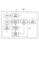
- FIG. 1 is a diagram showing an example of the configuration of a non-destructive testing apparatus 100 according to the first embodiment.
- the non-destructive testing apparatus 100 is a type of computer equipment that includes a control section 1, a transmitting section 2, and a receiving section 3, and has a computer inside.
- the non-destructive inspection apparatus 100 non-destructively inspects the object for defects, etc.
- Typical examples of objects to be subjected to non-destructive testing include composite fiber resins such as CFRP and solid objects such as reinforced concrete, but the object is not limited thereto, and liquids and gases are also contemplated.
- CFRP composite fiber resins
- solid objects such as reinforced concrete
- liquids and gases are also contemplated.
- the control unit 1 is composed of a processor such as a CPU (Central Processing Unit) or a microprocessor, or an arithmetic circuit such as an ASIC (Application Specific Integrated Circuit) or an FPGA (Field Programmable Gate Array), and has a plurality of functional blocks. .
- the control unit 1 uses a plurality of functional blocks to provide the transmitting unit 2 with control information regarding transmission conditions such as wave transmission timing and transmission waveform, and provides control information to the receiving unit 3.
- a predetermined signal processing, etc. is performed on the received wave signal outputted from 3, and the test result is output or displayed.
- the transmitter 2 transmits predetermined waves to the object based on control information provided from the controller 1.
- waves transmitted by the transmitter 2 include acoustic waves such as ultrasonic waves, and electromagnetic waves such as radio waves and light waves.
- the transmitter 2 transmits ultrasonic waves.
- the wavefront shape of the wave transmitted by the transmitter 2 is assumed to be a plane wave, a spherical wave, etc., but in the following, it is assumed that the waveform is a plane wave, that is, a wave having a wavefront in a direction perpendicular to the propagation direction.
- the wave generating elements constituting the transmitter 2 may have either a single element configuration or a multiple element configuration as long as a desired wavefront shape can be obtained.
- the receiving unit 3 is arranged to face the transmitting unit 2 with the object in between, for example, and receives waves transmitted from the transmitting unit 2 and propagated through the object C based on control information provided from the control unit 1. do.
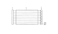
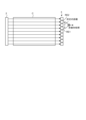
- FIG. 2 is a diagram illustrating the positional relationship between the transmitter 2, the receiver 3, and the object C.
- the transmitter 2 is placed on one side of the two opposing surfaces of the object C, and the receiver 3 is placed on the other side. , are placed respectively.
- the receiving unit 3 has a plurality of receiving elements and is configured to be able to receive the waves propagated through the object C at a plurality of receiving positions in space (black circles in FIG. 2).
- the plurality of reception positions are arranged on a plane or on a straight line that is substantially orthogonal to the wave transmission direction, and each reception element of the reception unit 3 is configured to receive signals that propagate through the object C at each of the plurality of reception positions.
- Receive waves Thereby, the receiving unit 3 receives the plane waves transmitted by the transmitting unit 2 and having a wavefront perpendicular to the propagation direction almost simultaneously by the receiving elements arranged at a plurality of receiving positions, and converts them into electrical signals. It can be output.
- the expression “substantially perpendicular” refers not only to the state in which the transmission direction and the plane or straight line are truly orthogonal, but also to the transmission direction that may occur due to installation tolerances of the transmitting section 2 and the receiving section 3, etc. It also includes a state in which the direction and the plane or straight line are slightly deviated from the state in which they are truly orthogonal.
- this figure shows a so-called transmission-reception configuration in which the transmitter 2 and the receiver 3 are placed on different sides of the object C, it is also possible to place the transmitter 2 and the receiver 3 on the same side.
- a so-called reflective system structure may also be used.
- FIG. 3A and 3B show the transmitter 2, the receiver 3, and the object C viewed from the side.
- FIG. 3A shows waves received at each reception position when there is no structure such as a defect that reflects or scatters waves inside the object C.
- the transmitting unit 2 has a configuration including a plurality of transmitting elements, for example similar to the receiving unit 3, and by aligning the timing of the transmitting signals input to each transmitting element, the transmitting unit 2 outputs the signals from each transmitting element. Generate a plane wave by aligning the wavefronts of the waves.
- the waves output from the transmitter 2 reach each receiving element of the receiver 3 at the same timing. do. That is, the plurality of receiving elements of the receiving section 3 can be regarded as receiving simultaneously a plurality of rectilinear waves (arrows in FIG. 3A) that are simultaneously transmitted from the transmitting section 2 and travel in parallel.
- FIG. 3B shows an example of waves received at each reception position when there is a structure that reflects waves, such as a defect, inside the object C.
- the wave output from the transmitter 2 travels straight through the object C.
- the rectilinear wave propagating near the defect D is reflected by the boundary surface of the defect D and reaches, for example, the second receiving element RE2 placed next to it, instead of the first receiving element RE1 that was originally supposed to reach it.
- the reflected wave Wd is received.
- the second receiving element RE2 receives both the rectilinear wave Ws1 and the reflected wave Wd.
- FIG. 3B shows how the wave is reflected at the upper side of the interface of the defect D
- a similar phenomenon can also occur at the lower side of the interface of the defect D.
- the angle at which the wave is reflected may change depending on conditions such as the angle of incidence of the wave on the defect interface, the position of incidence, and the shape of the defect.
- FIG. 3B shows how a wave is reflected outward from the center of the defect D (upward in FIG. 3B), but depending on the conditions, it can be diffracted inward from the defect center, causing the wave to There may be cases where the receiving element that the signal reaches changes.
- the waves that the receiving unit 3 receives with each receiving element change reflecting the internal structure of the object. Therefore, by processing and analyzing each received signal output from the plurality of receiving elements of the receiving section 3 using a predetermined method, it is possible to detect the presence or absence of a defect or the like inside the object.
- control section 1 includes an information generation section 10, a transmission control section 11, a reception control section 12, and a defect detection section 15. Further, the information generation section 10 includes a phase shift detection section 13 and a reference signal generation section 14.
- the transmission control unit 11 controls the transmission unit 2 to transmit waves to the object C under predetermined transmission conditions such as waveform, frequency, and transmission timing.
- the reception control unit 12 controls the reception unit 3 so that the reception element placed at a predetermined reception position receives the wave transmitted by the transmission unit 2 and propagated through the object C.
- the reference signal generation unit 14 generates a reference signal that is a wave whose waveform, frequency, etc. match the transmission signal output from the transmission unit 2 using a predetermined method and configuration. As shown in FIG. 3A, the reference signal is output from each receiving element under the condition that there is no structure inside the object that causes waves such as defects to be diffracted and each of the plurality of receiving elements receives only straight waves. It is a signal equivalent to the signal, or a signal similar to this. In the present invention, various methods can be adopted as a method for generating the reference signal. The method for generating the reference signal will be described later.
- the phase shift detection section 13 Based on the reference signal, the phase shift detection section 13 generates phase shift information indicating a change in the phase of the received signal output from the reception section 3 using a predetermined method. If a significant value is detected as the phase shift information, this means that there is a structure such as a defect that causes waves to be diffracted, etc. inside the object.
- FIG. 4 is a diagram conceptually explaining the processing contents for the phase shift detection unit 13 to generate phase shift information for a received signal outputted by a receiving element at a certain receiving position.
- the received signal is either a straight wave corresponding to the receiving position or a diffracted wave due to the defect etc. for each receiving element. Or contains both ingredients.
- FIG. 4 illustrates a case where the received signal includes only diffracted wave components.
- the reference signal corresponds to a received signal that is output when the receiving element receives only a straight wave component.
- the phase shift detection unit 13 combines the received signal, which is a diffracted wave, and a reference signal, which is a straight wave, performs nonlinear processing to calculate the interference component between both signals, and based on the magnitude thereof, obtains phase shift information. generate.
- a straight wave can be expressed as cos2 ⁇ f 1 t.
- t is time.
- the diffracted wave diffracts at the defect interface and reaches the receiving element as shown in FIG. 3B, the propagation time changes compared to the straight wave, and the phase changes with respect to the straight wave. That is, if the phase shift (phase difference) between the diffracted wave and the rectilinear wave is ⁇ , the diffracted wave can be expressed as cos(2 ⁇ f 1 t ⁇ ).
- Equation (1) the third term 2cos2 ⁇ f 1 t ⁇ cos (2 ⁇ f 1 t ⁇ ) is an interference component between the received signal and the reference signal. According to the product-sum formula, the third term is expressed by Equation 2 below.
- the graph on the right side of FIG. 4 schematically shows a frequency spectrum obtained when the received signal and the reference signal interfere.
- a second harmonic component center frequency 2f 1
- a DC component are obtained due to interference between the received signal and the reference signal.
- the former term corresponds to the second harmonic component
- the latter term corresponds to the DC component, respectively.
- the magnitude of the DC component (cos ⁇ ) calculated through such processing is output to the defect detection unit 15 as phase shift information of the diffracted wave component.
- the received signal has only a diffracted wave component
- the rectilinear wave component included in the received signal and the reference signal have the same waveform and frequency, and have a time difference corresponding to the time required for the rectilinear wave component to propagate through the object C.
- the reference signal has a sufficiently large amplitude and is combined with the received signal, the straight wave component included in the received signal can be ignored, so the nonlinear processing described above eliminates the interference component between the diffracted wave component in the received signal and the reference signal. can be generated.
- the reference signal generation unit 14 generates a reference signal using a predetermined method. Below, a method for generating the reference signal will be explained.
- the reference signal generation unit 14 generates the reference signal by, for example, performing a simulation using a calculation model of the target object.
- the computational model of the object is a virtual object created in arithmetic space that has internal parameters that substantially match those of the object C that is the inspection target of the non-destructive inspection device 100 and that has no internal defects. It's a model.
- the expression "substantially match” includes a case where there is a slight deviation in value between the internal parameters of the calculation model and the internal parameters of the object C due to an error or the like.
- a calculation model is generated based on a known parameter group such as physical property parameters and structural parameters that are required when designing and manufacturing the object C. Note that the calculation model does not necessarily need to be created by the non-destructive testing apparatus 100, and may be created by a separately provided external computer or the like.
- a wave having the same wave parameters (amplitude, phase, frequency, etc.) as the transmission signal output from the transmitting section 2 is input into the calculation model, and a plurality of receiving elements of the receiving section 3 are arranged respectively.
- a received signal observed at the same position as the receiving position is obtained through simulation and is used as a reference signal. Note that the simulation does not necessarily need to be performed by the nondestructive testing apparatus 100, and may be performed by a separately provided external computer or the like.
- the object to be non-destructively inspected is constructed as a calculation model in an arithmetic space, and a reference signal is generated by simulating wave propagation based on an actual transmitted signal.
- a reference signal is generated by simulating wave propagation based on an actual transmitted signal.
- the reference signal can be generated at a timing different from the timing at which the nondestructive inspection apparatus 100 performs the nondestructive inspection of the object C. That is, the reference signal generation unit 14 may generate the reference signal at the same timing when the non-destructive inspection apparatus 100 performs the actual inspection of the object C in real space, or may generate the reference signal at the same timing as when the non-destructive inspection apparatus 100 performs the actual inspection of the object C.
- the reference signals may be generated at different timings. For example, by generating a reference signal in advance of an actual non-destructive inspection and storing the data in a storage unit, etc. of the reference signal generation unit 14, the non-destructive inspection apparatus 100 during the actual inspection can be It is possible to reduce the workload and perform efficient inspections. Alternatively, the reference signal may be generated after the actual inspection.
- the object C to be subjected to non-destructive testing is made of a homogeneous material, but this is not necessarily the case, and objects with non-homogeneous materials or structures may also be used. It's okay.
- the present invention can also be applied to materials based on resin materials that contain fibers, such as CFRTP (Carbon Fiber Reinforced Thermo Plastics), which is a type of composite fiber resin, and materials that have a laminated structure such as CFRP.
- CFRTP Carbon Fiber Reinforced Thermo Plastics
- the destructive inspection device 100 is applicable.
- the defect detection section 15 detects the presence or absence of a defect, etc. inside the object C, and the size and position of the defect, etc., based on the phase shift information output from the phase shift detection section 13.
- the defect detection unit 15 detects a defect detection unit 15 when there is a reception position where significant phase shift information is detected among the reception positions where a plurality of reception elements of the reception unit 3 are arranged, or when there is a reception position that is unique compared to other reception positions. If there is a reception position from which phase shift information can be obtained, it is determined that a defect or the like exists within the object C. Note that the defect detection unit 15 determines that a defect or the like exists on or near a line connecting the receiving position and the transmitting unit 2 from which significant or unique phase shift information can be obtained.
- the nondestructive inspection device 100 propagates waves to a target object, acquires a received signal with receiving elements arranged at a plurality of receiving positions, and performs nonlinear processing on the received signal with a reference signal created or acquired in advance. By generating phase shift information of the received signal, even if the defect inside the object is minute, it can be detected easily and at low cost.
- the reference signal can be generated by a simulation in which a wave having the same parameters (frequency, etc.) as the wave transmitted by the transmitter 2 is input into a calculation model having internal parameters equivalent to those of the target object. It is possible to reduce the generation cost of , and the calculation cost of phase shift detection processing based on the reference signal and the received signal, thereby suppressing the inspection cost by the non-destructive inspection apparatus 100.
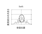
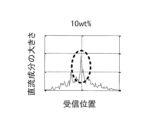
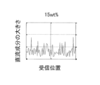
- FIGS. 5 and 6 show the relationship between the magnitude of the DC component included in the phase shift information output from the phase shift detection unit 13 and the reception position, respectively, using the content rate of carbon fiber in CFRTP as a parameter.
- the case where there is a gap with a diameter of 500 ⁇ m inside (FIG. 5) and the case where there is no gap (FIG. 6) are shown.
- the horizontal axis indicates the receiving position
- the vertical axis indicates the magnitude of the DC component of the phase shift information, respectively. Note that the air gap is located between the center of the horizontal axis (receiving position) in FIGS. 5 and 6 and the transmitting section.
- FIGS. 5A to 5D and FIGS. 6A to 6D show the carbon fiber content as a parameter.
- the carbon fiber content is 5% by weight
- the carbon fiber content is the same.
- 10% by weight FIGS. 5C and 6C show the case of 15% by weight
- FIGS. 5D and 6D show the case of 20% by weight, respectively.
- the variation in phase shift information (random vertical fluctuation) mainly seen in FIG. 6 is considered to be due to the influence of scattering etc. due to carbon fibers contained in CFRTP.
- the peak of the phase shift information caused by defects etc. is larger than the variation due to internal scattering etc.
- the non-destructive testing apparatus 100 As described above, according to the non-destructive testing apparatus 100 according to the first embodiment, even when the object contains fibers and the like and is not homogeneous, defects in the object can be easily and efficiently detected. Can be done.
- each receiving element (first receiving position) of the receiving section 3 is The received signal obtained by simulating the received signal in arithmetic space was used.
- a received signal at a second receiving position different from the first receiving position is used as a reference signal used to generate phase shift information at the first receiving position.
- FIG. 7 is a diagram showing an example of the configuration of a non-destructive testing apparatus 100A according to the second embodiment.
- the nondestructive testing apparatus 100A includes a control section 1A, a transmitting section 2, and a receiving section 3.
- the control section 1A includes an information generation section 10A, a transmission control section 11, a reception control section 12, and a defect detection section 15, and the information generation section 10A includes only a phase shift detection section 13A.
- components that perform operations similar to those in the first embodiment are given the same reference numerals as in the first embodiment, and descriptions thereof will be omitted.
- a non-destructive testing apparatus 100A according to the second embodiment shown in FIG. 7 differs from the non-destructive testing apparatus 100 according to the first embodiment in that it does not have a reference signal generation section 14.
- the phase shift detection section 13A uses another signal as the reference signal instead of the reference signal generated by the reference signal generation section 14 to detect the phase shift. process
- FIG. 8 is a diagram for explaining phase shift detection processing in the nondestructive testing apparatus 100A according to the second embodiment.
- FIG. 8 conceptually explains phase shift detection processing for the received signal generated by the first receiving element RE1 among the plurality of receiving elements.
- the received signal generated by the first receiving element RE1 the received signal generated by another receiving element disposed at a receiving position separated from the first receiving element RE1 by a predetermined distance is used as a reference signal.
- the phase shift detection process is performed using the FIG. 8 shows an example in which a received signal generated by another receiving element (second receiving element RE2) placed two reception positions adjacent to the first receiving element RE1 is used as a reference signal.
- the second embodiment and the first embodiment differ only in which signal is used as the reference signal, and the content of the phase shift detection process performed by the phase shift detection unit 13A is the same as the first embodiment. This is equivalent to the phase shift detection section 13 of the embodiment.
- phase shift detection processing is performed on the received signals generated by all the receiving elements, using the received signals generated by other receiving elements located a predetermined distance away as reference signals.
- phase shift detection processing even if the received signal generated by the first receiving element contains a diffracted wave component diffracted by a defect inside the object, the second receiving element located a predetermined distance away It is expected that the received signal generated by the element contains only straight wave components. In such a case, the phase shift information of the received signal can be extracted by performing the same phase shift detection process as in the first embodiment.
- the phase shift detection mechanism of the present invention is based on so-called correlation processing, and while the phase shift detection unit 13 in the first embodiment operates based on the principle of cross-correlation, the second embodiment operates based on the principle of cross-correlation.
- the phase shift detection unit 13A in the embodiment operates based on the principle of autocorrelation. Therefore, in the phase shift detection section 13A, the reference signal may be a received signal outputted by any receiving element separated by a predetermined distance in any direction from the receiving element that outputs the received signal, but more preferably , is appropriately determined depending on the amount of phase shift of the received signal to be detected and the size of defects etc. that are assumed to be included in the object.
- the results of correlation processing using multiple received signals output from multiple receiving elements separated by different distances, or by further performing statistical processing such as averaging on the results, more stable It is possible to extract phase shift information.
- the manufacturing cost for the reference signal generation unit 14 is reduced compared to the non-destructive testing device 100 of the first embodiment, and Non-destructive testing can be performed efficiently.
- FIG. 9 shows the relationship between the magnitude of the DC component included in the phase shift information output from the phase shift detection section 13A and the reception position, using the carbon fiber content rate of CFRTP as a parameter.
- Fig. 9A shows the case where the carbon fiber content is 5% by weight
- Fig. 9B shows the case when the carbon fiber content is 10% by weight
- Fig. 9C shows the case when the carbon fiber content is 15% by weight
- Fig. 9D shows the case when the carbon fiber content is 20% by weight.
- the horizontal axis in FIG. 9 indicates the receiving position
- the vertical axis indicates the magnitude of the DC component of the phase shift information. position) between the center of the transmitter and the transmitter.
- the phase shift information shows a peak depending on the position of the defect etc., similarly to FIG. 5. That is, when there is a defect inside the object, the phase shift information at the reception position corresponding to the defect position exhibits a peculiar behavior with respect to other reception positions.
- the non-destructive inspection apparatus 100A according to the second embodiment can also detect defects in the target object simply and efficiently.
- FIG. 10 is a diagram showing an example of the configuration of a non-destructive testing apparatus 100B according to the third embodiment.
- a non-destructive testing apparatus 100B includes a control section 1B, a transmitting section 2, and a receiving section 3. Further, the control section 1B includes an information generation section 10B, a transmission control section 11, a reception control section 12, and a defect detection section 15, and the information generation section 10B includes a phase shift detection section 13 and a reference signal generation section. 14, a nonlinear processing section 16, and a difference extraction section 17.
- the nondestructive inspection apparatus 100B further includes a nonlinear processing section 16 and a difference extraction section 17 in addition to the configuration of the nondestructive inspection apparatus 100.
- the nonlinear processing unit 16 performs nonlinear processing (product calculation) only on the reference signal for each receiving position. More specifically, the nonlinear processing unit 16 performs a square calculation on the reference signal and outputs the result.
- the difference extraction unit 17 extracts the difference between the phase shift information generated by the phase shift detection unit 13 and the nonlinear processing result generated by the nonlinear processing unit 16 for each reception position, and outputs the difference to the defect detection unit 15.
- the defect detection unit 15B uses this difference to determine the presence or absence of a defect.
- the non-destructive testing apparatus 100B it is possible to reduce the influence of variations in the reference signal for each reception position and more stably detect defects in the object. can.
- variations in the reference signal for each receiving position may occur due to the influence of wave scattering due to fibers, etc., for example, when a material that is not homogeneous is used as the object.
- the fourth embodiment differs from the first embodiment in that phase shift detection processing is performed on each of the received signal and the reference signal after removing the amplitude fluctuation (intensity) component.
- FIG. 11 is a diagram showing an example of the configuration of a non-destructive testing apparatus 100C according to the fourth embodiment.
- a non-destructive testing apparatus 100C includes a control section 1C, a transmitting section 2, and a receiving section 3. Further, the control section 1C includes an information generation section 10C, a transmission control section 11, a reception control section 12, and a defect detection section 15.
- the information generation section 10C includes a phase shift detection section 13, a reference signal generation section 14 , a first amplitude fluctuation removal section 18 , and a second amplitude fluctuation removal section 19 .
- the nondestructive testing apparatus 100C further includes a first amplitude fluctuation removing section 18 and a second amplitude fluctuation removing section 19.
- the first amplitude fluctuation removal unit 18 performs a process of removing the amplitude fluctuation component from the received signal generated by the reception unit 3 for each reception position.
- the second amplitude fluctuation removal unit 19 performs processing to remove the amplitude fluctuation component from the reference signal for each reception position corresponding to the reception position.
- the phase shift detection section 13 detects a change in the phase of the received signal output from the first amplitude fluctuation removal section 18 based on the reference signal output from the second amplitude fluctuation removal section 19. Generates phase shift information indicating .
- amplitude fluctuation removal processing is binarization processing using a predetermined threshold.
- the predetermined threshold value may be set to an appropriate value in advance. Further, as another example, saturation processing or clipping processing may be performed when the signal amplitude exceeds a predetermined value.
- the nondestructive testing apparatus 100C it is possible to reduce the influence of amplitude fluctuations of the received signal and the reference signal, and detect defects in the object with higher accuracy.
- the first amplitude fluctuation removal section 18 that performs amplitude fluctuation removal processing on the received signal and the second amplitude fluctuation removal section 19 that performs amplitude fluctuation removal processing on the reference signal are separately provided.
- the same amplitude fluctuation removal section may perform amplitude fluctuation removal processing on both the received signal and the reference signal.
- defects are detected by extracting information regarding the phase of the received signal.
- defects are detected using not only the phase shift information of the received signal but also the intensity information.
- FIG. 12 is a diagram showing an example of the configuration of a non-destructive testing device 100D according to the fifth embodiment.
- a non-destructive testing apparatus 100D includes a control section 1D, a transmitting section 2, and a receiving section 3. Further, the control section 1D includes an information generation section 10D, a transmission control section 11, a reception control section 12, a defect detection section 15D, a branching section 110, and an intensity information processing section 111. , a phase shift detection section 13, and a reference signal generation section 14.
- the nondestructive testing device 100D further includes a branching section 110 and a strength information processing section 111 in addition to the configuration of the nondestructive testing device 100.
- the branching section 110 branches the received signal output from the receiving section 3, and the phase shift detection section 13 outputs phase shift information of one of the branched received signals.
- the intensity information processing unit 111 performs predetermined processing on the other received signal branched by the branching unit 110 based on the intensity information of the received signal, such as extracting the intensity information.
- the defect detection unit 15D detects defects based on the phase information generated by the phase shift detection unit and the output information from the intensity information processing unit 111.
- the predetermined processing that the intensity information processing section 111 performs on the intensity information of the received signal and the predetermined processing that the defect detection section 15D performs on the phase shift information and the output information from the intensity information processing section 111 are described in this document.
- the invention is not particularly limited. As appropriate, it is possible to use known techniques for detecting defects and the like based on strength information of received signals.
- the reference signal generation unit 14 generated the reference signal
- the nondestructive testing device of the present invention may acquire a reference signal generated in advance by an external computer or the like, and perform testing using this.
- the non-destructive testing device of the present invention may store information regarding the reference signal generated in advance in a storage unit or the like, and read out and use the information from the storage unit during phase shift detection processing. good.
- the method for generating the reference signal is not limited to the above method, and for example, if the reference signal is obtained by actual measurement, this method may be used or used in combination.
- the reference signal is generated by simulation using a calculation model of the target object, but the present disclosure is not limited thereto.
- a calculation model of the object in arithmetic space we prepare another object (reference object) that is made of the same material, has the same structure, and does not contain any defects as the actual object for non-destructive testing, and It is also possible to actually input the wave to the reference object, obtain the data of the received signal, and create the reference signal based on this data.
- the transmitter 2 transmits a plane wave to the object C, but the present disclosure is not limited thereto.
- a spherical wave may be used.
- straight waves may be transmitted from a plurality of transmission positions corresponding to each of the plurality of reception positions. In this case, it is not necessary to transmit straight waves from all transmission positions at the same time, and transmission may be performed sequentially from a plurality of transmission positions, and a reception signal may be acquired at a reception position corresponding to the transmission position. In this case, by using the information on the transmission time and the reception time, it is possible to perform the same phase shift detection process as in the embodiment described above.
- the present invention is useful for non-destructive testing equipment.
- Nondestructive inspection device 1, 1A, 1B, 1C, 1D Control section 10, 10A, 10B, 10C, 10D Information generation section 11 Transmission control section 12 Reception control section 13, 13A Phase shift detection Section 14 Reference signal generation section 15, 15B, 15D Defect detection section 16 Nonlinear processing section 17 Difference extraction section 18 First amplitude fluctuation removal section 19 Second amplitude fluctuation removal section 110 Branching section 111 Intensity information processing section 2 Transmission section 3 Receiving section
Landscapes
- Engineering & Computer Science (AREA)
- Signal Processing (AREA)
- Physics & Mathematics (AREA)
- Health & Medical Sciences (AREA)
- Life Sciences & Earth Sciences (AREA)
- Chemical & Material Sciences (AREA)
- Analytical Chemistry (AREA)
- Biochemistry (AREA)
- General Health & Medical Sciences (AREA)
- General Physics & Mathematics (AREA)
- Immunology (AREA)
- Pathology (AREA)
- Investigating Or Analyzing Materials By The Use Of Ultrasonic Waves (AREA)
Priority Applications (1)
| Application Number | Priority Date | Filing Date | Title |
|---|---|---|---|
| JP2024536834A JPWO2024024309A1 (https=) | 2022-07-28 | 2023-06-13 |
Applications Claiming Priority (2)
| Application Number | Priority Date | Filing Date | Title |
|---|---|---|---|
| JP2022-120656 | 2022-07-28 | ||
| JP2022120656 | 2022-07-28 |
Publications (1)
| Publication Number | Publication Date |
|---|---|
| WO2024024309A1 true WO2024024309A1 (ja) | 2024-02-01 |
Family
ID=89706167
Family Applications (1)
| Application Number | Title | Priority Date | Filing Date |
|---|---|---|---|
| PCT/JP2023/021968 Ceased WO2024024309A1 (ja) | 2022-07-28 | 2023-06-13 | 非破壊検査装置、非破壊検査方法、およびプログラム |
Country Status (2)
| Country | Link |
|---|---|
| JP (1) | JPWO2024024309A1 (https=) |
| WO (1) | WO2024024309A1 (https=) |
Citations (10)
| Publication number | Priority date | Publication date | Assignee | Title |
|---|---|---|---|---|
| JPS541681A (en) * | 1977-05-17 | 1979-01-08 | Nat Res Dev | Sensing method and apparatus of change in object |
| JPS55159139A (en) * | 1979-05-31 | 1980-12-11 | Fuji Electric Co Ltd | Signal processing circuit of optic-acoustic analyzer |
| US4843847A (en) * | 1986-07-07 | 1989-07-04 | Canadian Patents And Development Limited | Apparatus and method for ultrasonically inspecting articles for internal defects |
| JPH0526854A (ja) * | 1991-07-23 | 1993-02-02 | Olympus Optical Co Ltd | 超音波測定装置 |
| JP2004515748A (ja) * | 2000-07-14 | 2004-05-27 | ロッキード マーティン コーポレイション | 超音波を用いて複合材料の気孔度を検出するシステムと方法 |
| JP2008545123A (ja) * | 2005-07-06 | 2008-12-11 | ナショナル・リサーチ・カウンシル・オブ・カナダ | 超音波減衰量を使用して材料特性を決定する方法及びシステム |
| JP2011196877A (ja) * | 2010-03-19 | 2011-10-06 | Jfe Steel Corp | 超音波計測方法および超音波計測装置 |
| JP2018054392A (ja) * | 2016-09-28 | 2018-04-05 | 株式会社日立製作所 | 検査装置及び検査方法 |
| WO2019021538A1 (ja) * | 2017-07-27 | 2019-01-31 | 株式会社Subaru | 超音波検査システムの製造方法 |
| JP2020094939A (ja) * | 2018-12-13 | 2020-06-18 | 株式会社ニコン | 検査装置、製造システム、検査方法、及び製造方法 |
-
2023
- 2023-06-13 JP JP2024536834A patent/JPWO2024024309A1/ja active Pending
- 2023-06-13 WO PCT/JP2023/021968 patent/WO2024024309A1/ja not_active Ceased
Patent Citations (10)
| Publication number | Priority date | Publication date | Assignee | Title |
|---|---|---|---|---|
| JPS541681A (en) * | 1977-05-17 | 1979-01-08 | Nat Res Dev | Sensing method and apparatus of change in object |
| JPS55159139A (en) * | 1979-05-31 | 1980-12-11 | Fuji Electric Co Ltd | Signal processing circuit of optic-acoustic analyzer |
| US4843847A (en) * | 1986-07-07 | 1989-07-04 | Canadian Patents And Development Limited | Apparatus and method for ultrasonically inspecting articles for internal defects |
| JPH0526854A (ja) * | 1991-07-23 | 1993-02-02 | Olympus Optical Co Ltd | 超音波測定装置 |
| JP2004515748A (ja) * | 2000-07-14 | 2004-05-27 | ロッキード マーティン コーポレイション | 超音波を用いて複合材料の気孔度を検出するシステムと方法 |
| JP2008545123A (ja) * | 2005-07-06 | 2008-12-11 | ナショナル・リサーチ・カウンシル・オブ・カナダ | 超音波減衰量を使用して材料特性を決定する方法及びシステム |
| JP2011196877A (ja) * | 2010-03-19 | 2011-10-06 | Jfe Steel Corp | 超音波計測方法および超音波計測装置 |
| JP2018054392A (ja) * | 2016-09-28 | 2018-04-05 | 株式会社日立製作所 | 検査装置及び検査方法 |
| WO2019021538A1 (ja) * | 2017-07-27 | 2019-01-31 | 株式会社Subaru | 超音波検査システムの製造方法 |
| JP2020094939A (ja) * | 2018-12-13 | 2020-06-18 | 株式会社ニコン | 検査装置、製造システム、検査方法、及び製造方法 |
Also Published As
| Publication number | Publication date |
|---|---|
| JPWO2024024309A1 (https=) | 2024-02-01 |
Similar Documents
| Publication | Publication Date | Title |
|---|---|---|
| Zhang et al. | Delamination damage imaging method of CFRP composite laminate plates based on the sensitive guided wave mode | |
| CN105987950B (zh) | 超声波探伤系统、超声波探伤方法及航空器零件制造方法 | |
| Baskaran et al. | Shear-wave time of flight diffraction (S-TOFD) technique | |
| Alem et al. | Reference-free damage identification in plate-like structures using lamb-wave propagation with embedded piezoelectric sensors | |
| Leckey et al. | Multiple-mode Lamb wave scattering simulations using 3D elastodynamic finite integration technique | |
| CN103292754B (zh) | 多介质层超声波测厚方法 | |
| Saini et al. | Optimisation of the half-skip total focusing method (HSTFM) parameters for sizing surface-breaking cracks | |
| Gresil et al. | Guidelines for using the finite element method for modeling guided Lamb wave propagation in SHM processes | |
| CN108872393A (zh) | 结构疲劳裂纹方向检测用非线性超声混频方法 | |
| Yu et al. | Detection of a single transverse crack in a CFRP cross-ply laminate by visualizing mode conversion of Lamb waves | |
| CN113945631A (zh) | 经由超声表征内部结构 | |
| KR101830461B1 (ko) | 기계 부품 내부에 존재하는 결함의 방향을 측정하기 위한 방법 및 그 장치 | |
| Stolze et al. | Phase/frequency analysis of diffuse Lamb-wave field for fatigue-crack detection in an aluminium multi-riveted strap joint aircraft panel | |
| An et al. | Debonding damage detection in CFRP-reinforced steel structures using scanning probabilistic imaging method improved by ultrasonic guided-wave transfer function | |
| Baghalian et al. | Development of comprehensive heterodyne effect based inspection (CHEBI) method for inclusive monitoring of cracks | |
| WO2024024309A1 (ja) | 非破壊検査装置、非破壊検査方法、およびプログラム | |
| KR101191364B1 (ko) | 비선형 평가 시스템 및 장치 | |
| US12203892B1 (en) | Detection and monitoring of cracks and fractures using nonlinear response to multimode acoustic signals | |
| Benzon et al. | Use of Fourier-based frequency-wavenumber domain filtering of simulated elastic waves for damage detection in fiber/polymer composites | |
| Elwalwal et al. | Crack inspection using guided waves (GWs)/structural health monitoring (SHM) | |
| Wang et al. | Automated characterization of debonding based on ultrasonic guided waves and a simulation-trained deep neural network | |
| Aldrin et al. | Scattering of obliquely incident shear waves from a cylindrical cavity | |
| Wang et al. | Shape reconstruction of plate thinning using reflection coefficients of ultrasonic lamb waves: a numerical approach | |
| Ricci et al. | Guided waves for detection of delamination and disbonding in stiffened composite panels | |
| Chu et al. | Ultrasonic edge waves for damage detection in composite plate stiffeners |
Legal Events
| Date | Code | Title | Description |
|---|---|---|---|
| 121 | Ep: the epo has been informed by wipo that ep was designated in this application |
Ref document number: 23846044 Country of ref document: EP Kind code of ref document: A1 |
|
| WWE | Wipo information: entry into national phase |
Ref document number: 2024536834 Country of ref document: JP |
|
| NENP | Non-entry into the national phase |
Ref country code: DE |
|
| 122 | Ep: pct application non-entry in european phase |
Ref document number: 23846044 Country of ref document: EP Kind code of ref document: A1 |