WO2024009677A1 - 音処理方法、音処理装置、およびプログラム - Google Patents
音処理方法、音処理装置、およびプログラム Download PDFInfo
- Publication number
- WO2024009677A1 WO2024009677A1 PCT/JP2023/021288 JP2023021288W WO2024009677A1 WO 2024009677 A1 WO2024009677 A1 WO 2024009677A1 JP 2023021288 W JP2023021288 W JP 2023021288W WO 2024009677 A1 WO2024009677 A1 WO 2024009677A1
- Authority
- WO
- WIPO (PCT)
- Prior art keywords
- volume adjustment
- sound
- performers
- trained model
- volume
- Prior art date
- Legal status (The legal status is an assumption and is not a legal conclusion. Google has not performed a legal analysis and makes no representation as to the accuracy of the status listed.)
- Ceased
Links
Images




Classifications
-
- G—PHYSICS
- G06—COMPUTING OR CALCULATING; COUNTING
- G06Q—INFORMATION AND COMMUNICATION TECHNOLOGY [ICT] SPECIALLY ADAPTED FOR ADMINISTRATIVE, COMMERCIAL, FINANCIAL, MANAGERIAL OR SUPERVISORY PURPOSES; SYSTEMS OR METHODS SPECIALLY ADAPTED FOR ADMINISTRATIVE, COMMERCIAL, FINANCIAL, MANAGERIAL OR SUPERVISORY PURPOSES, NOT OTHERWISE PROVIDED FOR
- G06Q30/00—Commerce
- G06Q30/04—Billing or invoicing
-
- H—ELECTRICITY
- H04—ELECTRIC COMMUNICATION TECHNIQUE
- H04R—LOUDSPEAKERS, MICROPHONES, GRAMOPHONE PICK-UPS OR LIKE ACOUSTIC ELECTROMECHANICAL TRANSDUCERS; ELECTRIC HEARING AIDS; PUBLIC ADDRESS SYSTEMS
- H04R3/00—Circuits for transducers
-
- H—ELECTRICITY
- H04—ELECTRIC COMMUNICATION TECHNIQUE
- H04S—STEREOPHONIC SYSTEMS
- H04S7/00—Indicating arrangements; Control arrangements, e.g. balance control
- H04S7/30—Control circuits for electronic adaptation of the sound field
-
- H—ELECTRICITY
- H04—ELECTRIC COMMUNICATION TECHNIQUE
- H04R—LOUDSPEAKERS, MICROPHONES, GRAMOPHONE PICK-UPS OR LIKE ACOUSTIC ELECTROMECHANICAL TRANSDUCERS; ELECTRIC HEARING AIDS; PUBLIC ADDRESS SYSTEMS
- H04R2430/00—Signal processing covered by H04R, not provided for in its groups
- H04R2430/01—Aspects of volume control, not necessarily automatic, in sound systems
-
- H—ELECTRICITY
- H04—ELECTRIC COMMUNICATION TECHNIQUE
- H04S—STEREOPHONIC SYSTEMS
- H04S2400/00—Details of stereophonic systems covered by H04S but not provided for in its groups
- H04S2400/11—Positioning of individual sound objects, e.g. moving airplane, within a sound field
-
- H—ELECTRICITY
- H04—ELECTRIC COMMUNICATION TECHNIQUE
- H04S—STEREOPHONIC SYSTEMS
- H04S2400/00—Details of stereophonic systems covered by H04S but not provided for in its groups
- H04S2400/13—Aspects of volume control, not necessarily automatic, in stereophonic sound systems
Definitions
- One embodiment of the present invention relates to a sound processing method, a sound processing device, and a program.
- Patent Document 1 discloses that a sound signal related to performance is received from audio mixers B2 and C3 via a network, a communication delay time between the audio mixers B2 and C3 is measured, and the communication delay time is calculated based on the measured communication delay time.
- An audio mixer is disclosed that mixes the sound signals of audio mixers B2 and C3 accordingly.
- Patent Document 2 discloses a configuration that smoothes the switching between pre-fader and post-fader by correcting the difference in volume between pre-fader and post-fader.
- Patent Document 3 discloses a configuration in which the impulse response from a speaker to a microphone is measured, and the volume is adjusted in consideration of the indirect sound component, thereby adjusting the volume to an appropriate volume in consideration of the indirect sound component.
- Patent Document 4 discloses a configuration in which the direct sound volume measurement result on the near end side and the distance between the speaker and the microphone are fed back to the far end side. This allows the far-end user to know that his or her own voice is being amplified correctly.
- Patent Document 5 discloses a configuration in which the volume of a sound signal received from the far end is adjusted based on an acoustic feature acquired by a microphone on the near end. As a result, the invention of Patent Document 5 can adjust the volume in consideration of the listening environment.
- Patent Document 6 discloses a configuration in which a plurality of amplifiers are arranged for a plurality of performers located at different locations on a stage, and a mixer adjusts and supplies the volume of the sound signal of each amplifier. Thereby, the mixer of Patent Document 6 can adjust the volume balance of a plurality of monitor speakers all at once.
- An embodiment of the present invention aims to provide a sound processing method that can appropriately adjust the volume balance of multiple performers in a virtual space.
- a sound processing method arranges objects of a plurality of performers and a plurality of volume adjustment interfaces corresponding to the objects of the plurality of performers in a virtual space, and provides a sound processing method for the plurality of performers.
- Receive a plurality of corresponding sound signals receive respective volume adjustment parameters for the plurality of performers corresponding to the plurality of volume adjustment interfaces from a user, and adjust the volume adjustment parameters for each of the plurality of performers of the plurality of sound signals.
- each volume adjustment parameter for the plurality of performers is determined, and the volume adjustment parameter is determined using the trained model.
- the volume of the plurality of sound signals is adjusted and mixed based on the volume adjustment parameter.
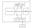
- FIG. 1 is a block diagram showing the configuration of a sound processing system 1.
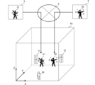
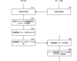
- FIG. It is a block diagram showing the structure of PC12C. It is a perspective view showing an example of a certain virtual three-dimensional space R1. It is a flowchart showing the operation of the PC 12C and the server 30 in the training stage. It is a flowchart showing the operation of the PC 12C in the execution stage. 12 is a flowchart showing the operation of the PC 12A (or PC 12B) according to Modification 1.
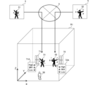
- FIG. 7 is a perspective view showing an example of a virtual three-dimensional space R1 according to Modification 2.
- FIG. FIG. 3 is a block diagram showing the configuration of a sound processing system 1A according to modification 4.
- FIG. 1 is a block diagram showing the configuration of the sound processing system 1.
- the sound processing system 1 according to FIG. 1 includes a PC (personal computer) 12A installed in a first venue 3, a PC 12B installed in a second venue 5, a PC 12C installed in a third venue 7, and a server 30.
- PC 12A, PC 12B, PC 12C, and server 30 are connected via network 9.
- PC12A, PC12B, and PC12C are examples of the sound processing device of the present invention.
- the PC 12A at the first venue 3 is connected to the guitar amplifier 11A and the motion sensor 13A.
- Guitar amplifier 11A is connected to electric guitar 10.
- the electric guitar 10 is an example of audio equipment.
- Guitar amplifier 11A is connected to electric guitar 10 via an audio cable.
- the guitar amplifier 11A is also an example of audio equipment.
- the guitar amplifier 11A is connected to the PC 12A by, for example, a USB cable.
- the guitar amplifier 11A may be connected to the PC 12A by wireless communication.
- Electric guitar 10 outputs analog sound signals related to performance sounds to guitar amplifier 11A.
- the guitar amplifier 11A has an analog audio terminal.
- Guitar amplifier 11A receives analog sound signals from electric guitar 10 via an audio cable.
- the guitar amplifier 11A converts the received analog sound signal into a digital sound signal.
- the guitar amplifier 11A performs various signal processing such as effects on the digital sound signal.
- the guitar amplifier 11A converts the digital sound signal after signal processing into an analog sound signal.
- the guitar amplifier 11A amplifies the analog sound signal.
- the guitar amplifier 11A outputs the performance sound of the electric guitar 10 based on the analog sound signal amplified via the built-in speaker. Furthermore, the guitar amplifier 11A transmits the digital sound signal after signal processing to the PC 12A.
- the user of the PC 12A is a player of the electric guitar 10.
- the player of the electric guitar 10 uses the PC 12A to distribute the sound of his/her performance and to operate a 3D model object that is his/her alter ego and performs virtually in the virtual space.
- the PC 12A controls motion data for controlling the motion of the object.
- the motion sensor 13A is a sensor for capturing the motion of the performer, and is, for example, an optical type, inertial type, or image type sensor.
- the motion sensor 13A is connected to the PC 12A by, for example, a USB cable.
- the PC 12A controls motion data based on sensor information received from the motion sensor 13A.
- the motion sensor 13A may be connected to the PC 12A by wireless communication.
- the PC 12A transmits to the server 30 the digital sound signal related to the guitar performance sound received from the guitar amplifier 11A and the motion data controlled based on the sensor information of the motion sensor 13A.
- the PC 12B at the second venue 5 is connected to the microphone 19 and motion sensor 13B.
- the microphone 19 is an example of audio equipment.
- the microphone 19 is connected to the PC 12B via an audio cable, a USB cable, or the like.
- PC 12B receives an analog audio signal from microphone 19 via an audio cable.
- the PC 12B converts the received analog sound signal into a digital sound signal.
- the microphone 19 may output the digital audio signal to the PC 12B via a USB cable or the like.
- the user of PC 12B is a singer.
- the singer uses the PC 12B to distribute his own singing sound and operate an object that is his alter ego, which virtually sings in the virtual space.
- the PC 12B controls motion data for controlling the motion of the object.
- the user who distributes the singing sound and the singer do not need to be the same person.
- the motion sensor 13B is a sensor for capturing the singer's motion, and is, for example, an optical type, inertial type, or image type sensor.
- the motion sensor 13B is connected to the PC 12B by, for example, a USB cable.
- the PC 12B controls motion data based on sensor information received from the motion sensor 13B.
- the motion sensor 13B may be connected to the PC 12B by wireless communication.
- the PC 12B transmits to the server 30 motion data controlled based on the digital sound signal related to the singing sound received from the microphone 19 and the sensor information from the motion sensor 13B.
- the PC 12C at the third venue 7 is connected to the headphones 20.
- Headphones 20 are also an example of audio equipment.
- the user of the PC 12C is a viewer who views a performer's performance virtually performed in a virtual space.
- FIG. 2 is a block diagram showing the configuration of the PC 12C.
- the PC 12C is a general-purpose information processing device.
- FIG. 2 shows the configuration of the PC 12C, the main configurations of the PC 12A and PC 12B are also the same as the configuration shown in FIG.
- the PC 12C includes a communication unit 11, a processor 12, a RAM 13, a flash memory 14, a display 15, a user I/F 16, and an audio I/F 17.
- the communication unit 11 has a wireless communication function such as Bluetooth (registered trademark) or Wi-Fi (registered trademark), and a wired communication function such as USB or LAN.
- a wireless communication function such as Bluetooth (registered trademark) or Wi-Fi (registered trademark)
- a wired communication function such as USB or LAN.
- the display 15 is composed of an LCD, an OLED, or the like.
- the display 15 displays the video output from the processor 12.
- the user I/F 16 is an example of an operation unit.
- the user I/F 16 includes a mouse, a keyboard, a touch panel, or the like.
- User I/F 16 accepts user operations.
- the touch panel may be stacked on the display 15.
- the audio I/F 17 has an analog audio terminal or a digital audio terminal, and is an interface for connecting audio equipment.
- the audio I/F 17 of the PC 12C connects headphones 20 as an example of audio equipment, and outputs a sound signal to the headphones 20.
- the processor 12 is composed of a CPU, DSP, SoC (System on a Chip), or the like.
- the processor 12 reads programs from the flash memory 14, which is a storage medium, and temporarily stores them in the RAM 13, thereby performing various operations. Note that the program does not need to be stored in the flash memory 14.
- the processor 12 may, for example, download the data from another device such as a server and temporarily store it in the RAM 13 if necessary.
- the processor 12 receives sound signals and motion data from the server 30 via the communication unit 11.
- the sound signals received from the server 30 include a first sound signal related to the performance sound of the performer in the first venue 3 and a second sound signal related to the singing sound of the singer in the second venue 5.
- the motion data received from the server 30 includes the motions of the performers at the first venue 3 and the motions of the singers at the second venue 5.
- the processor 12 also receives spatial information, model data, position information, etc. from the server 30 via the communication unit 11.
- Spatial information is information indicating the shape of a three-dimensional space corresponding to a live venue such as a live house or concert hall, and is expressed by three-dimensional coordinates with a certain position as the origin.
- the spatial information may be coordinate information based on 3D CAD data of an actual live venue such as a concert hall, or may be logical coordinate information (information normalized from 0 to 1) of a certain imaginary live venue. You can.
- the model data is three-dimensional CG image data for configuring a 3D model object, and is composed of multiple image parts.
- Model data is designated for each performer. For example, a performer at the first venue 3 specifies model data that becomes his/her alter ego.
- the server 30 distributes the specified model data.
- the position information is information indicating the position of model data in a three-dimensional space.
- the position information is represented by three-dimensional coordinates within the virtual space.
- the position information may be position information corresponding to model data whose position does not change, such as a device such as a speaker, or may be position information corresponding to model data whose position changes, such as a performer.
- FIG. 3 is a perspective view showing an example of a certain virtual three-dimensional space R1.
- the virtual three-dimensional space R1 in FIG. 3 shows a rectangular parallelepiped space as an example, the space may have any shape.
- the processor 12 Based on the spatial information and position information received from the server 30, the processor 12 places objects in a virtual three-dimensional space R1 as shown in FIG. Furthermore, the processor 12 sets the position of the user of the PC 12C within the virtual three-dimensional space R1. The position of the user of the PC 12C corresponds to the viewpoint position 50 in the virtual three-dimensional space R1.
- FIG. 3 shows an overhead view of the virtual three-dimensional space R1
- the processor 12 of the PC 12C creates a model based on spatial information, model data, position information, object motion data, and information on the set viewpoint position. The data is rendered to generate an image viewed from the set viewpoint position 50 in the virtual three-dimensional space R1. The generated video is displayed via the display 15.
- the viewer of the PC 12C can visually recognize the image viewed from the virtual three-dimensional space R1 from the set viewpoint position 50.
- the user of the PC 12C can change the viewpoint position 50 in the virtual three-dimensional space R1 via the user I/F 16.
- the processor 12 generates an image of the virtual three-dimensional space R1 viewed from the changed viewpoint position 50. Thereby, the user of the PC 12C can feel as if he or she is moving within the virtual three-dimensional space R1.
- the processor 12 of the PC 12C adjusts and mixes the volume of the plurality of sound signals received from the server 30, and generates, for example, a stereo (L, R) channel sound signal.
- the processor 12 mixes the first sound signal of the first venue 3 and the second sound signal of the second venue 5.
- the processor 12 outputs a stereo channel sound signal to the headphones 20 via the audio I/F 17.
- the processor 12 may perform effect processing such as equalizer processing and reverb processing on each of the first sound signal and the second sound signal. Further, the processor 12 may perform localization processing on the first sound signal and the second sound signal such that the sound is localized at the position of the corresponding object.
- the PC 12C uses a trained model trained on the relationship between the sound signal corresponding to each performer and the volume adjustment parameter corresponding to the sound signal to determine volume adjustment parameters for each of the plurality of performers. Adjust the volume of the sound signals and mix them.
- FIG. 4 is a flowchart showing the operations of the PC 12C and the server 30 during the training stage.
- the server 30 distributes the first sound signal and the second sound signal (S21).
- the processor 12 of the PC 12C receives the first sound signal and the second sound signal from the server 30 (S11).
- the processor 12 arranges a plurality of performer objects and a plurality of volume adjustment interfaces corresponding to the plurality of performer objects in the virtual space (S12).
- the processor 12 places the first object 51 corresponding to the performer 31 present at the first venue 3, which is a remote location.
- the processor 12 places the second object 52 corresponding to the singer 32 present in the second venue 5, which is another remote location, in the virtual three-dimensional space R1.
- the processor 12 arranges a first volume adjustment interface 71 corresponding to the first object 51 and a second volume adjustment interface 72 corresponding to the second object 52.
- the processor 12 arranges objects and volume adjustment interfaces corresponding to performers in two venues, the first venue 3 and the second venue 5, but the number of venues is limited to two. do not have.
- the processor 12 may further arrange performer objects and volume adjustment interfaces for a larger number of venues.
- the processor 12 receives volume adjustment parameters for a plurality of performers corresponding to a plurality of volume adjustment interfaces from the user of the PC 12C (S13).
- the user of the PC 12C operates the first volume adjustment interface 71 and the second volume adjustment interface 72 arranged in the virtual three-dimensional space R1 to perform a volume adjustment operation.
- the user of the PC 12C feels that the performance sound corresponding to the first object 51 is too loud, the user operates the first volume adjustment interface 71 to lower the volume.
- the first volume adjustment interface 71 and the second volume adjustment interface 72 are slider operators.
- the user of the PC 12C feels that the performance sound corresponding to the first object 51 is too loud, the user of the PC 12C moves the first volume adjustment interface 71 downward. Furthermore, if the user of the PC 12C feels that the singing sound corresponding to the second object 52 is too low, for example, the user moves the second volume adjustment interface 72 upward to increase the volume.
- the PC 12C transmits the received volume adjustment parameter to the server 30 (S14).
- the server 30 receives the volume adjustment parameter from the PC 12C (S22).
- the server 30 receives volume adjustment parameters from the PC 12C, but also receives volume adjustment parameters from many other information processing devices.
- the server 30 uses the received large number of volume adjustment parameters to train a predetermined model on the relationship between the volume adjustment parameters and the sound signals corresponding to the plurality of performers distributed using a predetermined algorithm (S23).
- the algorithm for training the model is not limited, and any machine training algorithm such as CNN (Convolutional Neural Network) or RNN (Recurrent Neural Network) can be used.
- the machine training algorithm may be supervised training, unsupervised training, semi-supervised training, reinforcement training, reverse reinforcement training, active training, transfer training, or the like.
- the server 30 may train the model using a machine training model such as a Hidden Markov Model (HMM) or a Support Vector Machine (SVM).
- HMM Hidden Markov Model
- SVM Support Vector Machine
- the predetermined model is trained to output a volume adjustment parameter that lowers the volume with respect to the sound signal of the performance sound at the first venue 3.
- the server 30 can generate a trained model by causing a predetermined model to train the relationship between each sound signal of a plurality of performers and each volume adjustment parameter.
- FIG. 5 is a flowchart showing the operation of the PC 12C in the execution stage.
- the processor 12 of the PC 12C receives the first sound signal, the second sound signal, and the trained model from the server 30 (S31). Note that the trained model may be received in advance separately from the first sound signal and the second sound signal.
- the processor 12 places objects of multiple performers in the virtual space (S32). Specifically, the processor 12 places the first object 51 and the second object 52 in the virtual three-dimensional space R1. In this example, the processor 12 does not arrange the first volume adjustment interface 71 and the second volume adjustment interface 72 in the execution stage.
- the processor 12 uses the trained model to determine volume adjustment parameters for each of the multiple performers (S33). As described above, the trained model has been trained on the relationship between each sound signal of a plurality of performers and each volume adjustment parameter. Therefore, the processor 12 uses the trained model to generate a first volume adjustment parameter and a second volume adjustment parameter corresponding to the first sound signal corresponding to the first object 51 and the second sound signal corresponding to the second object 52, respectively. Find the parameters.
- the processor 12 adjusts and mixes the volumes of the plurality of sound signals based on the volume adjustment parameters determined by the trained model (S34). Specifically, the processor 12 adjusts the volume of the first sound signal using the first volume adjustment parameter, adjusts the volume of the second sound signal using the second volume adjustment parameter, and adjusts the volume of the first sound signal and the volume-adjusted first sound signal. Mix the second sound signal.
- the PC 12C adjusts and mixes the sound signals of multiple performers to an appropriate volume balance using a trained model trained with volume adjustment parameters received from multiple users, thereby creating a virtual three-dimensional image. It is possible to appropriately adjust the volume balance of a plurality of performers who sing or perform virtually within the space R1. As a result, viewers who watch a performer's performance virtually performed in the virtual three-dimensional space R1 can easily enjoy a virtual performance in the virtual space with better volume balance without having to adjust the volume balance. Customers can enjoy the experience of being able to watch videos.
- the processor 12 did not arrange the first volume adjustment interface 71 and the second volume adjustment interface 72, but the first volume adjustment interface 71 and the second volume adjustment interface 72 may be placed.
- the user of the PC 12C can further finely adjust the first volume adjustment parameter and the second volume adjustment parameter determined by the processor 12 using the trained model.
- the PC 12C may also send the finely adjusted volume adjustment parameter to the server 30.
- Server 30 may also receive the fine-tuned volume adjustment parameters to further retrain the trained model.
- the volume adjustment parameter is updated as the performance progresses within the virtual three-dimensional space R1. Therefore, viewers viewing the performance can enjoy the customer experience of being able to view the performance at an appropriate volume balance at all times as the performance progresses within the virtual three-dimensional space R1.
- FIG. 6 is a flowchart showing the operation of the PC 12A (or PC 12B) according to the first modification.
- the PC 12C receives the trained model from the server 30, adjusts the volume of the first sound signal with the first volume adjustment parameter, adjusts the volume of the second sound signal with the second volume adjustment parameter, and adjusts the volume of the second sound signal with the second volume adjustment parameter.
- An example was shown in which the adjusted first sound signal and second sound signal are mixed.
- the volume adjustment parameter obtained using the trained model was the volume adjustment parameter used by the receiving device that mixes the received multiple sound signals.
- the transmitting side devices PC12A and PC12B each receive the trained model, adjust the volume of the first sound signal with the first volume adjustment parameter, and adjust the volume of the second sound signal. is adjusted using the second volume adjustment parameter.
- the PC 12A first receives a trained model from the server 30 (S41).
- the PC 12A uses the received trained model to determine the volume adjustment parameter of the sound signal to be transmitted (S42).
- the trained model has been trained on the relationship between each sound signal of a plurality of performers and each volume adjustment parameter. Therefore, the PC 12A can use the trained model to determine the first volume adjustment parameter corresponding to the first sound signal.
- the PC 12A adjusts the volume of the first sound signal based on the first volume adjustment parameter obtained using the trained model (S43).
- the PC 12A transmits the adjusted first sound signal to the server 30 (S44).
- the PC 12B adjusts the volume of the second sound signal using the second volume adjustment parameter based on the trained model.
- the volume adjustment parameter obtained using the trained model is the volume adjustment parameter used by multiple devices used by multiple performers, and each of the multiple devices is configured based on the volume adjustment parameter.
- the receiving device receives and mixes the plurality of sound signals whose volumes have been adjusted by the plurality of devices.
- the PC 12A (or PC 12B) adjusts the volume of the sound signal, but for example, the guitar amplifier 11A may adjust the volume of the sound signal based on the trained model, or the guitar amplifier 11A may adjust the volume of the sound signal based on the trained model.
- Guitar 10 may adjust the volume of the sound signal based on the trained model.
- the PC 12A may determine the volume adjustment parameter for the guitar amplifier 11A based on the trained model, input the volume adjustment parameter to the guitar amplifier 11A, and the guitar amplifier 11A may adjust the volume of the sound signal.
- the PC 12A may determine the volume adjustment parameter for the electric guitar 10 based on the trained model, input the volume adjustment parameter to the electric guitar 10, and the electric guitar 10 may adjust the volume of the sound signal.
- the trained model may be trained not only on the volume adjustment parameter but also on the relationship between the sound signal corresponding to each performer of the plurality of sound signals and the effect parameter of the effect processing applied to the sound signal.
- FIG. 7 is a perspective view showing an example of the virtual three-dimensional space R1 according to the second modification. Components common to those in FIG. 3 are denoted by the same reference numerals, and description thereof will be omitted.
- the processor 12 of the PC 12C places a plurality of performer objects and a plurality of effect adjustment interfaces corresponding to the plurality of performer objects in the virtual space. Specifically, the processor 12 arranges a first effect adjustment interface 71A corresponding to the first object 51 and a second effect adjustment interface 72A corresponding to the second object 52, as shown in FIG. .
- the first effect adjustment interface 71A and the second effect adjustment interface 72A are operators for adjusting the effect parameters of the equalizer, respectively.
- the first effect adjustment interface 71A and the second effect adjustment interface 72A each include operators for adjusting the levels of a high range (High), a middle range (Mid), and a low range (Low).
- the user of the PC 12C operates the first effect adjustment interface 71A and the second effect adjustment interface 72A to perform effect parameter adjustment operations.
- the PC 12C transmits the received effect parameters to the server 30.
- the server 30 receives effect parameters from a large number of information processing devices including the PC 12C.
- the server 30 uses the received large number of effect parameters to train a predetermined model on the relationship between the effect parameters and the sound signals corresponding to the plurality of performers distributed using a predetermined algorithm.
- the processor 12 of the PC 12C receives the first sound signal, the second sound signal, and the trained model from the server 30.
- the processor 12 uses the trained model to determine effect parameters for each of the plurality of performers' sound signals.
- the processor 12 performs effect processing on a plurality of sound signals based on effect parameters determined using the trained model. Further, the processor 12 adjusts the volume of the plurality of sound signals after effect processing and mixes them.
- the PC 12C of Modified Example 2 uses a trained model that has been trained with effect parameters received from multiple users to apply appropriate effect processing to the sound signals of multiple performers and mix them. It is possible to appropriately adjust the sound quality of a plurality of performers who sing or perform virtually in the three-dimensional space R1. As a result, viewers who watch a performer's performance performed virtually in the virtual three-dimensional space R1 can easily watch the virtual performance in the virtual space with better sound quality without having to adjust the effect parameters. Customers can enjoy the experience of being able to do things.
- the effect is not limited to the equalizer shown in the above example.
- the effect may be a compressor or other effect such as reverb.
- the user of the PC 12C adjusts the effect parameters so that strong reverb processing is applied to the sound of the performance at the first venue 3.
- the server 30 receives effect parameters from a large number of information processing devices including the PC 12C, and generates a trained model that applies strong reverb processing to the performance sound of the first venue 3.
- strong reverb processing is automatically applied to the performance sound of the first venue 3, so the viewer does not need to adjust the effect parameters that apply strong reverb processing to the performance sound of the first venue 3.
- customers can enjoy the experience of being able to easily watch virtual performances in a virtual space with better sound quality.
- the effect processing may be performed not by the receiving PC 12C but by the transmitting PC 12A, PC 12B, guitar amplifier 11A, electric guitar 10, microphone 19, etc.
- the transmitting side PCs 12A and 12B receive the trained model from the server 30, determine effect parameters based on the trained model, and perform effect processing.
- the guitar amplifier 11A may obtain effect parameters based on a trained model and perform effect processing, or the electric guitar 10 may obtain effect parameters based on a trained model and perform effect processing.
- the PC 12A determines effect parameters for effect processing in the guitar amplifier 11A based on the trained model, inputs the effect parameters to the guitar amplifier 11A, and performs effect processing based on the input effect parameters. Good too.
- the PC 12A may determine effect parameters for effect processing in the electric guitar 10 based on the trained model, input the effect parameters to the electric guitar 10, and the electric guitar 10 may perform the effect processing.
- the sound processing system 1 acquires information on a plurality of audio devices used by a plurality of performers, and performs effect processing on a plurality of sound signals based on the acquired information on the plurality of audio devices. Adjust effect parameters.
- the PC 12A transmits information about the electric guitar 10 and the guitar amplifier 11A to the server 30.
- the information on the electric guitar 10 and the guitar amplifier 11A includes, for example, information such as the model name or serial number of the electric guitar 10 and the guitar amplifier 11A.
- the PC 12B sends information about the microphone 19 to the server 30, and the PC 12C sends information about the headphones 20 to the server 30.
- the server 30 stores information on a plurality of audio devices and effect parameters such as appropriate equalizers corresponding to each audio device as a table.
- the server 30 reads the effect parameters corresponding to the audio equipment information received from the PC 12A, PC 12B, or PC 12C from the table, and transmits the read effect parameters to the PC 12A, PC 12B, or PC 12C.
- the PC 12A, PC 12B, or PC 12C receives the effect parameters from the server 30 and adjusts the effect parameters for effect processing to be applied to the sound signal of the corresponding audio device. For example, the PC 12C adjusts the equalizer parameters of the sound signal output to the headphones 20 based on the effect parameters received from the server 30.
- the sound quality will be different when a performer uses a certain audio device (for example, a certain microphone) to deliver the singing sound, and when a performer uses a different audio device (for example, a different microphone) to deliver the singing sound.
- a performer uses a different audio device (for example, a different microphone) to deliver the singing sound.
- the sound quality of the delivered singing sound may differ due to differences in the recording environment due to differences in audio equipment.
- the sound processing system 1 of the third modification it is possible to correct such differences in the recording environment due to differences in audio equipment.
- the server may obtain the effect parameters of the corresponding audio equipment using a trained model that has been trained on the relationship between information on a plurality of audio equipment and appropriate effect parameters corresponding to each audio equipment.
- FIG. 8 is a block diagram showing the configuration of a sound processing system 1A according to a fourth modification. Components that are the same as those in FIG. 1 are designated by the same reference numerals, and their description will be omitted.
- a performer at the first venue 3 and a performer at the second venue 5 transmit sound signals related to performance sounds or singing sounds to each other and perform a remote session.
- the PC 12A receives a sound signal related to the singing sound of the performer at the second venue 5, adjusts the volume, and outputs it to the headphones 20A.
- the performers at the first venue 3 listen to the singing sounds of the performers at the second venue 5 via the headphones 20A. Furthermore, the performers at the first venue 3 use the PC 12A to adjust the volume of the singing sounds of the performers at the second venue 5, and perform a performance in accordance with the singing sounds.
- the PC 12B receives a sound signal related to the performance sound of the performer at the first venue 3, adjusts the volume, and outputs it to the headphones 20B.
- the performers at the second venue 5 listen to the performance sounds of the performers at the first venue 3 via the headphones 20B. Furthermore, the performer at the second venue 5 uses the PC 12B to adjust the volume of the performance sound of the performer at the first venue 3, and performs a performance in accordance with the performance sound.
- the server 30 receives the volume adjustment parameters adjusted by the PC 12A and the PC 12B, and trains a predetermined model. Thereby, the server 30 can generate a trained model trained for the band.
- the band member receives the trained model from the server 30 using the information processing device, and adjusts the volume using the trained model.
- the performers on the PCs 12A and 12B can enjoy the customer experience of being able to conduct a remote session at a better volume than previously adjusted without having to perform volume adjustment operations.
- the above-mentioned sound processing system 1A is an example in which a remote session is performed at the first venue 3 and the second venue 5.
- the sound processing system 1A can also transmit and receive sound signals related to performance sounds or singing sounds at a larger number of venues, and perform remote ensemble performances in which each performer performs in tune with other performers.
- the PC 12C of the fifth modification adjusts and mixes the volume of the plurality of received sound signals based on the first position information of the objects of the plural performers and the second position information of the viewer.
- the processor 12 of the PC 12C generates a first sound signal and a second sound signal based on the distance between the user's viewpoint position 50 and the first object 51 and the distance between the viewpoint position 50 and the second object 52 in the virtual three-dimensional space R1. Adjust the volume of the sound signal.
- the processor 12 of the PC 12C increases the volume of a sound signal corresponding to an object that is close to the viewpoint position 50, and decreases the volume of a sound signal that corresponds to an object that is far from the viewpoint position 50.
- the viewer who views the performer's performance virtually performed in the virtual three-dimensional space R1 can enjoy the customer experience of being able to view the performance while being aware of the distance between himself and the performer in the virtual three-dimensional space R1.
- the PC 12C of the sixth modification performs audio processing using the viewpoint position 50 as a listening point based on the viewpoint position 50, the position of the first object 51, and the position of the second object 52.
- the sound processing using the viewpoint position 50 for listening is, for example, localization processing.
- the processor 12 of the PC 12C performs localization processing such that the sounds of the first object 51 and the second object 52 are localized at the positions of the first object 51 and the second object 52 when viewed from the viewpoint position 50.
- the processor 12 performs localization processing based on, for example, HRTF (Head Related Transfer Function).
- the HRTF represents a transfer function from a certain virtual sound source position to the user's right ear and left ear. For example, as shown in FIG. 3, the position of the first object 51 is on the front left side when viewed from the viewpoint position 50.
- the processor 12 performs binaural processing in which the sound signal corresponding to the first object 51 is convolved with an HRTF that is localized to the front left side of the user. Thereby, the user of the PC 12C can feel as if he or she is at the viewpoint position 50 in the virtual three-dimensional space R1 and is listening to the sound of the first object 51 in front of and on the left side of the user.
- the server 30 receives volume adjustment parameters from a large number of information processing devices and trains a predetermined model in the training stage.
- the server 30 may receive the volume adjustment parameter from one information processing device and train a predetermined model.
- the server 30 when a skilled operator performs a volume balance adjustment operation, the server 30 generates a trained model trained on the volume adjustment operation of the skilled operator, and distributes the trained model. Thereby, the trained model is shared by a large number of information processing devices. Other information processing devices perform volume adjustment using the distributed trained model.
- the server 30 may receive volume adjustment parameters adjusted by the members of the band and train a predetermined model. Thereby, the server 30 can generate a trained model trained for the band.
- the band member receives the trained model from the server 30 using the information processing device, and adjusts the volume using the trained model.
- band members conducting remote sessions can enjoy the customer experience of being able to perform remote sessions with a better volume balance than previously adjusted, without having to adjust the volume balance.
- the server 30 may retrain a trained model trained using the volume adjustment parameter received from a certain information processing device.
- the server 30 may receive the volume adjustment parameter again from the one information processing device and retrain the trained model, or may receive the volume adjustment parameter from another information processing device and retrain the trained model. May be retrained.
- the user may input the volume adjustment parameter by voice input such as "increase the volume of the first performer” instead of using an operator such as a slider.
- the operator of the sound processing system including the server 30 may provide a performance environment within the virtual three-dimensional space R1 and may also sell trained models.
- the server 30 is configured to perform billing processing on a specific trained model and download the trained model after billing is confirmed.
- the billing process may be performed not by the server 30 but by another billing server.
- the server 30 allows the user to download a trained model, which has been trained, for example, by a certain skilled operator's volume adjustment operation.
- the server 30 may perform a payment process to pay the skilled operator a remuneration each time a trained model is downloaded.
- the operator of the sound processing system including the server 30 may provide incentives to the operator. This allows operators to sell their own volume adjustment techniques. Therefore, the operator can increase the motivation of many users to use the sound processing system.
- the server 30 may accumulate a plurality of trained models trained with the volume adjustment parameters of a plurality of operators.
- the server 30 causes the information processing device used by the viewer to download any trained model designated by the viewer from among the plurality of trained models.
- the server 30 may perform a process of paying a reward to the operator who trained the downloaded trained model. Thereby, the operator can increase the motivation of a large number of operators to use the sound processing system.
- billing process may be billing on a monthly or yearly basis (subscription) instead of billing for each download.
Landscapes
- Business, Economics & Management (AREA)
- Physics & Mathematics (AREA)
- Engineering & Computer Science (AREA)
- Development Economics (AREA)
- Acoustics & Sound (AREA)
- Signal Processing (AREA)
- Finance (AREA)
- Economics (AREA)
- Accounting & Taxation (AREA)
- Marketing (AREA)
- Strategic Management (AREA)
- General Business, Economics & Management (AREA)
- General Physics & Mathematics (AREA)
- Theoretical Computer Science (AREA)
- Circuit For Audible Band Transducer (AREA)
- Electrophonic Musical Instruments (AREA)
Abstract
音処理方法は、仮想空間内に複数の演者のオブジェクトと、前記複数の演者のオブジェクトに対応する複数の音量調整用インタフェースと、を配置し、前記複数の演者にそれぞれ対応する複数の音信号を受信し、利用者から、前記複数の音量調整用インタフェースに対応する、前記複数の演者に対するそれぞれの音量調整パラメータを受け付けて、前記複数の音信号の各演者に対応する音信号と、該音信号に対応する前記音量調整パラメータと、の関係を訓練された訓練済モデルを用いて、前記複数の演者に対するそれぞれの音量調整パラメータを求めて、前記訓練済モデルで求めた該音量調整パラメータに基づいて前記複数の音信号の音量を調整して混合する。
Description
本発明の一実施形態は、音処理方法、音処理装置、およびプログラムに関する。
特許文献1には、オーディオ・ミキサーB2,C3からネットワークを介してパフォーマンスに係る音信号を受信し、オーディオ・ミキサーB2,C3との間の通信遅延時間を測定し、測定された通信遅延時間に応じてオーディオ・ミキサーB2,C3の音信号をミキシングする、オーディオ・ミキサーが開示されている。
特許文献2には、プリフェーダとポストフェーダの音量差を補正することで、プリフェーダとポストフェーダの切り替えをスムーズにする構成が開示されている。
特許文献3には、スピーカからマイクに至るインパルス応答を測定し、間接音成分を考慮して音量調整を行うことで、間接音成分を考慮した適切な音量に調整する構成が開示されている。
特許文献4には、近端側の直接音の音量測定結果とスピーカとマイクの距離を遠端側にフィードバックする構成が開示されている。これにより、遠端側ユーザは、自身の声が正しく拡声されていることを知ることができる。
特許文献5には、近端側のマイクで取得した音響特徴量に基づいて遠端側から受信した音信号の音量調整を行う構成が開示されている。これにより特許文献5の発明は、聴取環境を考慮した音量調整を行うことができる。
特許文献6には、ステージ上の異なる場所に位置する複数演者に複数のアンプを配置し、ミキサで各アンプの音信号の音量を調整して供給する構成が開示されている。これにより、特許文献6のミキサは、複数のモニタ用スピーカの音量バランスを一括して調整することができる。
先行技術文献に開示された構成は、いずれも仮想空間上の複数の演者の音量バランスを調整するものではない。
本発明の一実施形態は、仮想空間上の複数の演者の音量バランスを適切に調整することができる音処理方法を提供することを目的とする。
本発明の一実施形態に係る音処理方法は、仮想空間内に複数の演者のオブジェクトと、前記複数の演者のオブジェクトに対応する複数の音量調整用インタフェースと、を配置し、前記複数の演者にそれぞれ対応する複数の音信号を受信し、利用者から、前記複数の音量調整用インタフェースに対応する、前記複数の演者に対するそれぞれの音量調整パラメータを受け付けて、前記複数の音信号の各演者に対応する音信号と、該音信号に対応する前記音量調整パラメータと、の関係を訓練された訓練済モデルを用いて、前記複数の演者に対するそれぞれの音量調整パラメータを求めて、前記訓練済モデルで求めた該音量調整パラメータに基づいて前記複数の音信号の音量を調整して混合する。
本発明の一実施形態によれば、仮想空間上の複数の演者の音量バランスを適切に調整することができる。
図1は、音処理システム1の構成を示すブロック図である。図1に係る音処理システム1は、第1会場3に設置されたPC(パーソナルコンピュータ)12A、第2会場5に設置されたPC12B、第3会場7に設置されたPC12C、およびサーバ30を含む。PC12A、PC12B、PC12C、およびサーバ30は、ネットワーク9を介して接続される。PC12A、PC12B、およびPC12Cは、本発明の音処理装置の一例である。
第1会場3のPC12Aは、ギターアンプ11Aおよびモーションセンサ13Aに接続される。ギターアンプ11Aは、エレキギター10と接続される。
エレキギター10は、音響機器の一例である。ギターアンプ11Aは、オーディオケーブルを介してエレキギター10に接続される。ギターアンプ11Aも音響機器の一例である。また、ギターアンプ11Aは、例えばUSBケーブルによりPC12Aに接続される。無論、ギターアンプ11Aは、無線通信によりPC12Aに接続してもよい。エレキギター10は、演奏音に係るアナログ音信号をギターアンプ11Aに出力する。
ギターアンプ11Aは、アナログオーディオ端子を有する。ギターアンプ11Aは、オーディオケーブルを介してエレキギター10からアナログ音信号を受け付ける。ギターアンプ11Aは、受け付けたアナログ音信号をデジタル音信号に変換する。ギターアンプ11Aは、当該デジタル音信号にエフェクト等の各種の信号処理を施す。ギターアンプ11Aは、信号処理後のデジタル音信号をアナログ音信号に変換する。ギターアンプ11Aは、当該アナログ音信号を増幅する。ギターアンプ11Aは、内蔵スピーカを介して増幅されたアナログ音信号に基づいて、エレキギター10の演奏音を出力する。また、ギターアンプ11Aは、信号処理後のデジタル音信号を、PC12Aに送信する。
PC12Aのユーザは、エレキギター10の演奏者である。エレキギター10の演奏者は、PC12Aを用いて、自身の演奏音を配信するとともに仮想空間内で仮想的に演奏を行う自身の分身となる3Dモデルのオブジェクトを動作させる。ただし、演奏音の配信を行うユーザと演奏者とは同じ人物である必要はない。PC12Aは、当該オブジェクトの動作を制御するためのモーションデータを制御する。
モーションセンサ13Aは、演奏者のモーションをキャプチャするためのセンサであり、例えば光学式、慣性式、あるいは画像式等のセンサである。モーションセンサ13Aは、例えばUSBケーブルによりPC12Aに接続される。PC12Aは、モーションセンサ13Aから受け付けたセンサ情報に基づいてモーションデータを制御する。無論、モーションセンサ13Aは、無線通信によりPC12Aに接続してもよい。
PC12Aは、ギターアンプ11Aから受信したギター演奏音に係るデジタル音信号、およびモーションセンサ13Aのセンサ情報に基づいて制御したモーションデータをサーバ30に送信する。
第2会場5のPC12Bは、マイク19およびモーションセンサ13Bに接続される。
マイク19は、音響機器の一例である。マイク19は、オーディオケーブルあるいはUSBケーブル等を介してPC12Bに接続される。PC12Bは、オーディオケーブルを介してマイク19からアナログオーディオ信号を受信する。PC12Bは、受信したアナログ音信号をデジタル音信号に変換する。あるいは、マイク19は、USBケーブル等を介してデジタルオーディオ信号をPC12Bに出力してもよい。
PC12Bのユーザは、歌唱者である。歌唱者は、PC12Bを用いて、自身の歌唱音を配信するとともに仮想空間内で仮想的に歌唱を行う自身の分身となるオブジェクトを動作させる。PC12Bは、当該オブジェクトの動作を制御するためのモーションデータを制御する。ただし、歌唱音の配信を行うユーザと歌唱者とは同じ人物である必要はない。
モーションセンサ13Bは、歌唱者のモーションをキャプチャするためのセンサであり、例えば光学式、慣性式、あるいは画像式等のセンサである。モーションセンサ13Bは、例えばUSBケーブルによりPC12Bに接続される。PC12Bは、モーションセンサ13Bから受け付けたセンサ情報に基づいてモーションデータを制御する。無論、モーションセンサ13Bは、無線通信によりPC12Bに接続してもよい。
PC12Bは、マイク19から受信した歌唱音に係るデジタル音信号、およびモーションセンサ13Bのセンサ情報に基づいて制御したモーションデータをサーバ30に送信する。
第3会場7のPC12Cは、ヘッドフォン20に接続される。ヘッドフォン20も音響機器の一例である。PC12Cのユーザは、仮想空間内で仮想的に行われる演者のパフォーマンスを視聴する視聴者である。
図2は、PC12Cの構成を示すブロック図である。PC12Cは、汎用の情報処理装置である。図2では、PC12Cの構成を示すが、PC12AおよびPC12Bの主要構成も、図2に示す構成と同じである。
PC12Cは、通信部11、プロセッサ12、RAM13、フラッシュメモリ14、表示器15、ユーザI/F16、およびオーディオI/F17を備えている。
通信部11は、例えばBluetooth(登録商標)またはWi-Fi(登録商標)等の無線通信機能、USBまたはLAN等の有線通信機能を有する。
表示器15は、LCDやOLED等からなる。表示器15は、プロセッサ12の出力した映像を表示する。
ユーザI/F16は、操作部の一例である。ユーザI/F16は、マウス、キーボード、あるいはタッチパネル等からなる。ユーザI/F16は、利用者の操作を受け付ける。なお、タッチパネルは、表示器15に積層されていてもよい。
オーディオI/F17は、アナログオーディオ端子またはデジタルオーディオ端子等を有し、音響機器を接続するためのインタフェースである。本実施形態では、PC12CのオーディオI/F17は、音響機器の一例としてヘッドフォン20を接続し、ヘッドフォン20に音信号を出力する。
プロセッサ12は、CPU、DSP、またはSoC(System on a Chip)等からなる。プロセッサ12は、記憶媒体であるフラッシュメモリ14からプログラムを読み出し、RAM13に一時記憶することで、種々の動作を行う。なお、プログラムは、フラッシュメモリ14に記憶している必要はない。プロセッサ12は、例えば、サーバ等の他装置から必要な場合にダウンロードしてRAM13に一時記憶してもよい。
プロセッサ12は、通信部11を介して、サーバ30から音信号およびモーションデータを受信する。サーバ30から受信する音信号は、第1会場3の演奏者の演奏音に係る第1音信号および第2会場5の歌唱者の歌唱音に係る第2音信号を含む。サーバ30から受信するモーションデータは、第1会場3の演奏者のモーションおよび第2会場5の歌唱者のモーションを含む。また、プロセッサ12は、通信部11を介して、サーバ30から空間情報、モデルデータ、および位置情報等も受信する。
空間情報は、例えばライブハウスやコンサートホール等のライブ会場に対応する3次元空間の形状を示す情報であり、ある位置を原点とした3次元の座標で表される。空間情報は、実在のコンサートホール等のライブ会場の3DCADデータに基づく座標情報であってもよいし、ある架空のライブ会場の論理的な座標情報(0~1で正規化された情報)であってもよい。
モデルデータは、3Dモデルのオブジェクトを構成するための3次元CG画像データであり、複数の画像パーツからなる。モデルデータは、演者毎に指定される。例えば第1会場3の演奏者は、自身の分身となるモデルデータを指定する。サーバ30は、指定されたモデルデータを配信する。
位置情報は、3次元空間内におけるモデルデータの位置を示す情報である。位置情報は、上記仮想空間内の3次元の座標で表される。位置情報は、スピーカ等の機器の様に位置変化のないモデルデータに対応する位置情報である場合もあるし、演者の様に位置変化するモデルデータに対応する位置情報である場合もある。
図3は、ある仮想3次元空間R1の一例を示す斜視図である。図3の仮想3次元空間R1は、一例として直方体形状の空間を示しているが、空間の形状はどの様なものであってもよい。
プロセッサ12は、サーバ30から受信した空間情報および位置情報に基づいて、図3に示す様な仮想3次元空間R1にオブジェクトを配置する。また、プロセッサ12は、仮想3次元空間R1内に、PC12Cの利用者の位置を設定する。PC12Cの利用者の位置は、仮想3次元空間R1内の視点位置50に対応する。図3では、仮想3次元空間R1を俯瞰して示すが、PC12Cは、プロセッサ12は、空間情報、モデルデータ、位置情報、およびオブジェクトのモーションデータ、および設定した視点位置の情報に基づいて、モデルデータをレンダリングして、設定した視点位置50から仮想3次元空間R1を見た映像を生成する。生成した映像は、表示器15を介して表示する。これにより、PC12Cの視聴者は、設定した視点位置50から仮想3次元空間R1を見た映像を視認することができる。PC12Cのユーザは、ユーザI/F16を介して、仮想3次元空間R1内の視点位置50を変更することができる。プロセッサ12は、変更された視点位置50から仮想3次元空間R1を見た映像を生成する。これにより、PC12Cのユーザは、仮想3次元空間R1内で自身が移動しているように知覚することができる。
PC12Cのプロセッサ12は、サーバ30から受信した複数の音信号の音量を調整して混合し、例えばステレオ(L,R)チャンネルの音信号を生成する。この例では、プロセッサ12は、第1会場3の第1音信号および第2会場5の第2音信号を混合する。プロセッサ12は、オーディオI/F17を介してヘッドフォン20にステレオチャンネルの音信号を出力する。
なお、プロセッサ12は、第1音信号および第2音信号のそれぞれにイコライザやリバーブ処理等のエフェクト処理を行ってもよい。また、プロセッサ12は、第1音信号および第2音信号に対し、それぞれの対応するオブジェクトの位置に音が定位する様な定位処理を行ってもよい。
PC12Cは、各演者に対応する音信号と、該音信号に対応する音量調整パラメータと、の関係を訓練された訓練済モデルを用いて、複数の演者に対するそれぞれの音量調整パラメータを求めて、複数の音信号の音量を調整して混合する。
図4は、訓練段階におけるPC12Cおよびサーバ30の動作を示すフローチャートである。サーバ30は、第1音信号および第2音信号を配信する(S21)。PC12Cのプロセッサ12は、サーバ30から第1音信号および第2音信号を受信する(S11)。
プロセッサ12は、仮想空間内に複数の演者のオブジェクトと、複数の演者のオブジェクトに対応する複数の音量調整用インタフェースと、を配置する(S12)。
具体的には、プロセッサ12は、図3に示す様に、遠隔地である第1会場3に存在する演奏者31に対応する第1オブジェクト51を配置する。プロセッサ12は、別の遠隔地である第2会場5に存在する歌唱者32に対応する第2オブジェクト52を仮想3次元空間R1内に配置する。さらに、プロセッサ12は、第1オブジェクト51に対応する第1音量調整用インタフェース71および第2オブジェクト52に対応する第2音量調整用インタフェース72を配置する。なお、本実施形態では、プロセッサ12は、第1会場3および第2会場5の2つの会場の演者に対応するオブジェクトおよび音量調整用インタフェースを配置しているが、会場の数は2つに限らない。プロセッサ12は、さらに多数の会場の演者のオブジェクトおよび音量調整用インタフェースを配置してもよい。
次に、プロセッサ12は、PC12Cのユーザから、複数の音量調整用インタフェースに対応する、複数の演者に対するそれぞれの音量調整パラメータを受け付ける(S13)。PC12Cのユーザは、図3に示した様に、仮想3次元空間R1内に配置された第1音量調整用インタフェース71および第2音量調整用インタフェース72を操作して、音量調整操作を行う。PC12Cのユーザは、例えば、第1オブジェクト51に対応する演奏音が大きすぎると感じた場合に、第1音量調整用インタフェース71を操作して音量を下げる操作を行う。図3の例では、第1音量調整用インタフェース71および第2音量調整用インタフェース72は、スライダの操作子になっている。したがって、PC12Cのユーザは、第1オブジェクト51に対応する演奏音が大きすぎると感じた場合に、第1音量調整用インタフェース71を下方向に移動させる。また、PC12Cのユーザは、例えば、第2オブジェクト52に対応する歌唱音が小さすぎると感じた場合に、第2音量調整用インタフェース72を上方向に移動させ、音量を上げる操作を行う。
PC12Cは、受け付けた音量調整パラメータをサーバ30に送信する(S14)。サーバ30は、PC12Cから音量調整パラメータを受信する(S22)。この例では、サーバ30は、PC12Cから音量調整パラメータを受信しているが、他にも多数の情報処理装置から音量調整パラメータを受信する。サーバ30は、受信した多数の音量調整パラメータを用いて、所定のモデルに、所定のアルゴリズムを用いて配信した複数の演者に対応する音信号と音量調整パラメータとの関係を訓練させる(S23)。
本実施形態において、モデルを訓練させるためのアルゴリズムは限定されず、CNN(Convolutional Neural Network)やRNN(Recurrent Neural Network)等の任意の機械訓練アルゴリズムを用いることができる。機械訓練アルゴリズムは、教師あり訓練、教師なし訓練、半教師訓練、強化訓練、逆強化訓練、能動訓練、あるいは転移訓練等であってもよい。また、サーバ30は、HMM(Hidden Markov Model:隠れマルコフモデル)やSVM(Support Vector Machine)等の機械訓練モデルを用いてモデルを訓練させてもよい。
例えば、ある特定の演者(例えば第1会場3の演奏者31)の演奏音が、多数の視聴者で音量が大きすぎると感じられた場合、多数の視聴者が音量を下げる操作を行う。この場合、所定のモデルは、第1会場3の演奏音の音信号に対して、音量を下げる様な音量調整パラメータを出力するように訓練される。この様に、複数の演者のそれぞれの音信号と、それぞれの音量調整パラメータは、相関関係を有する。したがって、サーバ30は、所定のモデルに、複数の演者のそれぞれの音信号と、それぞれの音量調整パラメータと、の関係を訓練させ、訓練済モデルを生成することができる。
図5は、実行段階におけるPC12Cの動作を示すフローチャートである。PC12Cのプロセッサ12は、サーバ30から第1音信号、第2音信号、および訓練済モデルを受信する(S31)。なお、訓練済モデルは、第1音信号および第2音信号とは別に事前に受信してもよい。
プロセッサ12は、仮想空間内に複数の演者のオブジェクトを配置する(S32)。具体的には、プロセッサ12は、第1オブジェクト51および第2オブジェクト52を仮想3次元空間R1内に配置する。この例では、実行段階においてプロセッサ12は第1音量調整用インタフェース71および第2音量調整用インタフェース72を配置しない。
プロセッサ12は、訓練済モデルを用いて、複数の演者に対するそれぞれの音量調整パラメータを求める(S33)。上述の様に、訓練済モデルは、複数の演者のそれぞれの音信号と、それぞれの音量調整パラメータと、の関係を訓練されている。したがって、プロセッサ12は、訓練済モデルを用いて、第1オブジェクト51に対応する第1音信号および第2オブジェクト52に対応する第2音信号にそれぞれ対応する第1音量調整パラメータおよび第2音量調整パラメータを求める。
プロセッサ12は、訓練済モデルで求めた音量調整パラメータに基づいて複数の音信号の音量を調整して混合する(S34)。具体的には、プロセッサ12は、第1音信号の音量を第1音量調整パラメータで調整し、第2音信号の音量を第2音量調整パラメータで調整し、音量調整後の第1音信号および第2音信号を混合する。
この様に、PC12Cは、複数の利用者から受け付けた音量調整パラメータで訓練された訓練済モデルを用いて複数の演者の音信号を適切な音量バランスに調整して混合することで、仮想3次元空間R1内で仮想的に歌唱または演奏を行う複数の演者の音量バランスを適切に調整することができる。これにより、仮想3次元空間R1で仮想的に行われる演者のパフォーマンスを視聴する視聴者は、音量バランスの調整操作を行う必要なく、仮想空間内における仮想的な演奏をより良い音量バランスで簡単に視聴できるという顧客体験を享受できる。
なお、この例では、実行段階においてプロセッサ12は、第1音量調整用インタフェース71および第2音量調整用インタフェース72を配置しなかったが、第1音量調整用インタフェース71および第2音量調整用インタフェース72を配置してもよい。この場合、PC12Cのユーザは、プロセッサ12が訓練済モデルを用いて求めた第1音量調整パラメータおよび第2音量調整パラメータをさらに微調整することができる。また、PC12Cは、微調整を行った音量調整パラメータもサーバ30に送信してもよい。サーバ30は、微調整を行った音量調整パラメータも受信して、訓練済モデルをさらに再訓練してもよい。これにより、仮想3次元空間R1内で行われるパフォーマンスの進行に伴って音量調整パラメータが更新される。そのため、パフォーマンスを視聴する視聴者は、仮想3次元空間R1内で行われるパフォーマンスの進行に合わせて常に適切な音量バランスで視聴できるという顧客体験を享受できる。
(変形例1)
図6は、変形例1に係るPC12A(またはPC12B)の動作を示すフローチャートである。
図6は、変形例1に係るPC12A(またはPC12B)の動作を示すフローチャートである。
上記実施形態では、PC12Cがサーバ30から訓練済モデルを受信し、第1音信号の音量を第1音量調整パラメータで調整し、第2音信号の音量を第2音量調整パラメータで調整し、音量調整後の第1音信号および第2音信号を混合する例を示した。つまり、訓練済モデルで求めた音量調整パラメータは、受信した複数の音信号を混合する受信側機器で用いられる音量調整パラメータであった。
変形例1の音処理システム1では、送信側の機器であるPC12AおよびPC12Bがそれぞれ訓練済モデルを受信し、第1音信号の音量を第1音量調整パラメータで調整し、第2音信号の音量を第2音量調整パラメータで調整する。
具体的には、PC12Aは、まずサーバ30から訓練済モデルを受信する(S41)。PC12Aは、受信した訓練済モデルを用いて、送信する音信号の音量調整パラメータを求める(S42)。上述の様に、訓練済モデルは、複数の演者のそれぞれの音信号と、それぞれの音量調整パラメータと、の関係を訓練されている。したがって、PC12Aは、訓練済モデルを用いて、第1音信号に対応する第1音量調整パラメータを求めることができる。PC12Aは、訓練済モデルで求めた第1音量調整パラメータに基づいて第1音信号の音量を調整する(S43)。PC12Aは、調整後の第1音信号をサーバ30に送信する(S44)。PC12Bも同様に、訓練済モデルに基づいて第2音信号の音量を第2音量調整パラメータで調整する。
つまり、変形例1において、訓練済モデルで求めた音量調整パラメータは、複数の演者でそれぞれ利用される複数の機器で用いられる音量調整パラメータであり、複数の機器は、それぞれ、音量調整パラメータに基づいて複数の音信号の音量を調整し、受信側の機器は、複数の機器で音量を調整された後の複数の音信号を受信して混合する。
これにより、変形例1の音処理システム1でも、仮想3次元空間R1で仮想的に行われる演者のパフォーマンスを視聴する視聴者は、音量バランスの調整操作を行う必要なく、仮想空間内における仮想的な演奏をより良い音量バランスで簡単に視聴できるという顧客体験を享受できる。
なお、変形例1では、PC12A(またはPC12B)が音信号の音量を調整する例を示したが、例えばギターアンプ11Aが訓練済モデルに基づいて音信号の音量を調整してもよいし、エレキギター10が訓練済モデルに基づいて音信号の音量を調整してもよい。あるいは、PC12Aが訓練済モデルに基づいてギターアンプ11Aにおける音量調整パラメータを求めて、該音量調整パラメータをギターアンプ11Aに入力し、ギターアンプ11Aが音信号の音量を調整してもよい。あるいは、PC12Aが訓練済モデルに基づいてエレキギター10における音量調整パラメータを求めて、該音量調整パラメータをエレキギター10に入力し、エレキギター10が音信号の音量を調整してもよい。
(変形例2)
訓練済モデルは、音量調整パラメータだけでなく、複数の音信号の各演者に対応する音信号と、該音信号に施すエフェクト処理のエフェクトパラメータとの関係を訓練されてもよい。
訓練済モデルは、音量調整パラメータだけでなく、複数の音信号の各演者に対応する音信号と、該音信号に施すエフェクト処理のエフェクトパラメータとの関係を訓練されてもよい。
図7は、変形例2に係る仮想3次元空間R1の一例を示す斜視図である。図3と共通する構成については同一の符号を付し、説明を省略する。
PC12Cのプロセッサ12は、訓練段階として、仮想空間内に複数の演者のオブジェクトと、複数の演者のオブジェクトに対応する複数のエフェクト調整用インタフェースと、を配置する。具体的には、プロセッサ12は、図7に示す様に、第1オブジェクト51に対応する第1エフェクト調整用インタフェース71Aおよび第2オブジェクト52に対応する第2エフェクト調整用インタフェース72Aと、を配置する。
この例では、第1エフェクト調整用インタフェース71Aおよび第2エフェクト調整用インタフェース72Aは、それぞれイコライザのエフェクトパラメータを調整するための操作子である。第1エフェクト調整用インタフェース71Aおよび第2エフェクト調整用インタフェース72Aは、それぞれ高音域(High)、中音域(Mid)、および低音域(Low)のレベルを調整する操作子を含む。
PC12Cのユーザは、第1エフェクト調整用インタフェース71Aおよび第2エフェクト調整用インタフェース72Aを操作して、エフェクトパラメータの調整操作を行う。
PC12Cは、受け付けたエフェクトパラメータをサーバ30に送信する。サーバ30は、PC12Cを含む多数の情報処理装置からエフェクトパラメータを受信する。サーバ30は、受信した多数のエフェクトパラメータを用いて、所定のモデルに、所定のアルゴリズムを用いて配信した複数の演者に対応する音信号とエフェクトパラメータとの関係を訓練させる。
実行段階において、PC12Cのプロセッサ12は、サーバ30から第1音信号、第2音信号、および訓練済モデルを受信する。プロセッサ12は、訓練済モデルを用いて、複数の演者の音信号に施すそれぞれのエフェクトパラメータを求める。プロセッサ12は、訓練済モデルで求めたエフェクトパラメータに基づいて複数の音信号にエフェクト処理を施す。また、プロセッサ12は、エフェクト処理後の複数の音信号の音量を調整して混合する。
この様に、変形例2のPC12Cは、複数の利用者から受け付けたエフェクトパラメータで訓練された訓練済モデルを用いて複数の演者の音信号に適切なエフェクト処理を施して混合することで、仮想3次元空間R1内で仮想的に歌唱または演奏を行う複数の演者の音質を適切に調整することができる。これにより、仮想3次元空間R1で仮想的に行われる演者のパフォーマンスを視聴する視聴者は、エフェクトパラメータの調整操作を行う必要なく、仮想空間内における仮想的な演奏をより良い音質で簡単に視聴できるという顧客体験を享受できる。
なお、エフェクトは、上記の例で示したイコライザに限らない。エフェクトは、コンプレッサ、あるいはリバーブ等その他のエフェクトであってもよい。例えば、PC12Cのユーザは、第1会場3の演奏音に響きがないと感じた場合に、第1会場3の演奏音に強いリバーブ処理をかけるように、エフェクトパラメータを調整する。サーバ30は、PC12Cを含む多数の情報処理装置からエフェクトパラメータを受信し、第1会場3の演奏音に強いリバーブ処理をかける様な訓練済モデルを生成する。これにより、第1会場3の演奏音には、自動的に強いリバーブ処理が施されるため、視聴者は、改めて第1会場3の演奏音に強いリバーブ処理をかけるエフェクトパラメータを調整する必要なく、仮想空間内における仮想的な演奏をより良い音質で簡単に視聴できるという顧客体験を享受できる。
なお、エフェクト処理は、受信側のPC12Cではなく、送信側のPC12A、PC12B、あるいはギターアンプ11Aやエレキギター10、マイク19等で行ってもよい。この場合、送信側のPC12AおよびPC12Bが、訓練済モデルをサーバ30から受信して、該訓練済モデルに基づいてエフェクトパラメータを求めて、エフェクト処理を施す。また、ギターアンプ11Aが訓練済モデルに基づいてエフェクトパラメータを求めてエフェクト処理を行ってもよいし、エレキギター10が訓練済モデルに基づいてエフェクトパラメータを求めてエフェクト処理を行ってもよい。あるいは、PC12Aが訓練済モデルに基づいてギターアンプ11Aにおけるエフェクト処理のエフェクトパラメータを求めて、該エフェクトパラメータをギターアンプ11Aに入力し、ギターアンプ11Aが入力したエフェクトパラメータに基づいてエフェクト処理を行ってもよい。あるいは、PC12Aが訓練済モデルに基づいてエレキギター10におけるエフェクト処理のエフェクトパラメータを求めて、該エフェクトパラメータをエレキギター10に入力し、エレキギター10がエフェクト処理を行ってもよい。
(変形例3)
変形例3に係る音処理システム1は、複数の演者でそれぞれ利用される複数の音響機器の情報を取得し、取得した複数の音響機器の情報に基づいて、複数の音信号に施すエフェクト処理のエフェクトパラメータを調整する。
変形例3に係る音処理システム1は、複数の演者でそれぞれ利用される複数の音響機器の情報を取得し、取得した複数の音響機器の情報に基づいて、複数の音信号に施すエフェクト処理のエフェクトパラメータを調整する。
例えば、PC12Aは、エレキギター10およびギターアンプ11Aの情報をサーバ30に送信する。エレキギター10およびギターアンプ11Aの情報とは、例えばエレキギター10およびギターアンプ11Aのそれぞれの機種名、あるいは製造番号等の情報を含む。同様に、PC12Bは、マイク19の情報をサーバ30に送信し、PC12Cは、ヘッドフォン20の情報をサーバ30に送信する。
サーバ30は、複数の音響機器の情報とそれぞれの音響機器に対応する適切なイコライザ等のエフェクトパラメータをテーブルとして記憶している。サーバ30は、PC12A、PC12B、またはPC12Cから受信した音響機器の情報に対応するエフェクトパラメータをテーブルから読み出して、読み出したエフェクトパラメータをPC12A、PC12B、またはPC12Cに送信する。
PC12A、PC12B、またはPC12Cは、サーバ30からエフェクトパラメータを受信して、対応する音響機器の音信号に施すエフェクト処理のエフェクトパラメータを調整する。例えば、PC12Cは、サーバ30から受信したエフェクトパラメータに基づいて、ヘッドフォン20に出力する音信号のイコライザのパラメータを調整する。
これにより、各会場の利用者は、利用する音響機器のイコライザ等のエフェクトパラメータを手動で調整する必要なく、適切なエフェクトパラメータに簡単に調整できるという顧客体験を享受できる。例えば、ある演者がある音響機器(例えばあるマイク)を用いて歌唱音を配信する場合と、別のある音響機器(別のあるマイク)を用いて歌唱音を配信する場合と、で音質が異なる場合がある。この様に、音響機器の違いによる収録環境の差により、配信される歌唱音の音質が異なる場合がある。しかし、変形例3の音処理システム1では、この様な音響機器の違いによる収録環境の差を補正することができる。
なお、サーバは、複数の音響機器の情報とそれぞれの音響機器に対応する適切なエフェクトパラメータとの関係を訓練した訓練済モデルを用いて、対応する音響機器のエフェクトパラメータを求めてもよい。
(変形例4)
図8は、変形例4に係る音処理システム1Aの構成を示すブロック図である。図1と同じ構成については同じ符号を付し、説明を省略する。音処理システム1Aは、第1会場3の演者および第2会場5の演者が、互いに演奏音または歌唱音に係る音信号を送信し、リモートセッションを行う。
図8は、変形例4に係る音処理システム1Aの構成を示すブロック図である。図1と同じ構成については同じ符号を付し、説明を省略する。音処理システム1Aは、第1会場3の演者および第2会場5の演者が、互いに演奏音または歌唱音に係る音信号を送信し、リモートセッションを行う。
PC12Aは、第2会場5の演者の歌唱音に係る音信号を受信し、音量を調整してヘッドフォン20Aに出力する。第1会場3の演者は、ヘッドフォン20Aを介して第2会場5の演者の歌唱音を聴く。また、第1会場3の演者は、PC12Aを用いて第2会場5の演者の歌唱音の音量を調整して、当該歌唱音に合わせた演奏を行う。
PC12Bは、第1会場3の演者の演奏音に係る音信号を受信し、音量を調整してヘッドフォン20Bに出力する。第2会場5の演者は、ヘッドフォン20Bを介して第1会場3の演者の演奏音を聴く。また、第2会場5の演者は、PC12Bを用いて第1会場3の演者の演奏音の音量を調整して、当該演奏音に合わせた演奏を行う。
サーバ30は、PC12AおよびPC12Bでそれぞれ調整された音量調整パラメータを受信し、所定のモデルを訓練する。これにより、サーバ30は、当該バンド用に訓練した訓練済モデルを生成することができる。バンドメンバーは、次にリモートセッションを行う場合、情報処理装置を用いてサーバ30から訓練済モデルを受信し、訓練済モデルを用いて音量調整を行う。
これにより、PC12AおよびPC12Bの演者は、音量の調整操作を行う必要なく、過去に調整したより良い音量でリモートセッションを行うことができるという顧客体験を享受できる。
なお、上記の音処理システム1Aは、第1会場3および第2会場5でリモートセッションを行う例である。しかし、音処理システム1Aは、さらに多数の会場で演奏音または歌唱音に係る音信号を送受信し、それぞれの演者が他の演者に合わせて演奏を行う、リモート合奏を行うこともできる。
(変形例5)
変形例5のPC12Cは、複数の演者のオブジェクトの第1位置情報と、視聴者の第2位置情報とに基づいて受信した複数の音信号の音量を調整して混合する。
変形例5のPC12Cは、複数の演者のオブジェクトの第1位置情報と、視聴者の第2位置情報とに基づいて受信した複数の音信号の音量を調整して混合する。
例えば、PC12Cのプロセッサ12は、仮想3次元空間R1内のユーザの視点位置50と第1オブジェクト51の距離、および視点位置50と第2オブジェクト52の距離に基づいて、第1音信号および第2音信号の音量を調整する。PC12Cのプロセッサ12は、視点位置50との距離の近いオブジェクトに対応する音信号の音量を大きくし、視点位置50との距離の遠いオブジェクトに対応する音信号の音量を小さくする。
これにより、仮想3次元空間R1で仮想的に行われる演者のパフォーマンスを視聴する視聴者は、仮想3次元空間R1における自身と演者との距離感を認識しながら視聴できるという顧客体験を享受できる。
(変形例6)
変形例6のPC12Cは、視点位置50、第1オブジェクト51の位置、および第2オブジェクト52の位置に基づいて視点位置50を受聴点とした音響処理を施す。視点位置50を受聴とした音響処理とは、例えば定位処理である。
変形例6のPC12Cは、視点位置50、第1オブジェクト51の位置、および第2オブジェクト52の位置に基づいて視点位置50を受聴点とした音響処理を施す。視点位置50を受聴とした音響処理とは、例えば定位処理である。
PC12Cのプロセッサ12は、例えば、視点位置50から見て第1オブジェクト51および第2オブジェクト52の位置に第1オブジェクト51および第2オブジェクト52の音が定位する様な定位処理を行う。
プロセッサ12は、例えばHRTF(Head Related Transfer Function)に基づく定位処理を行う。HRTFは、ある仮想の音源位置から利用者の右耳および左耳に至る伝達関数を表す。例えば、図3に示す様に、第1オブジェクト51の位置は、視点位置50から見て前方左側である。プロセッサ12は、第1オブジェクト51に対応する音信号に、ユーザの前方左側の位置に定位する様なHRTFを畳み込むバイノーラル処理を行う。これにより、PC12Cのユーザは、仮想3次元空間R1内の視点位置50に居て、自身の前方左側の第1オブジェクト51の音を聴いている様に知覚することができる。
(変形例7)
上記実施形態では、いずれも訓練段階において、サーバ30が多数の情報処理装置から音量調整パラメータを受信し、所定のモデルを訓練する例を示した。しかし、サーバ30は、ある1つの情報処理装置から音量調整パラメータを受信し、所定のモデルを訓練してもよい。例えば熟練のオペレータが音量バランスの調整操作を行った場合、サーバ30は、当該熟練のオペレータの音量調整操作を訓練した訓練済モデルを生成し、当該訓練済モデルを配信する。これにより、当該訓練済モデルは、多数の情報処理装置で共有される。他の情報処理装置は、配信された訓練済モデルを用いて音量調整を行う。
上記実施形態では、いずれも訓練段階において、サーバ30が多数の情報処理装置から音量調整パラメータを受信し、所定のモデルを訓練する例を示した。しかし、サーバ30は、ある1つの情報処理装置から音量調整パラメータを受信し、所定のモデルを訓練してもよい。例えば熟練のオペレータが音量バランスの調整操作を行った場合、サーバ30は、当該熟練のオペレータの音量調整操作を訓練した訓練済モデルを生成し、当該訓練済モデルを配信する。これにより、当該訓練済モデルは、多数の情報処理装置で共有される。他の情報処理装置は、配信された訓練済モデルを用いて音量調整を行う。
これにより、仮想3次元空間R1で仮想的に行われる演者のパフォーマンスを視聴する視聴者は、音量バランスの調整操作を行う必要なく、熟練のオペレータにより調整されたより良い音量バランスで仮想的な演奏をより簡単に視聴できるという顧客体験を享受できる。
また、サーバ30は、あるバンドのメンバーでリモートセッションを行う場合に、当該バンドのメンバーで調整された音量調整パラメータを受信し、所定のモデルを訓練してもよい。これにより、サーバ30は、当該バンド用に訓練した訓練済モデルを生成することができる。バンドメンバーは、次にリモートセッションを行う場合、情報処理装置を用いてサーバ30から訓練済モデルを受信し、訓練済モデルを用いて音量調整を行う。
これにより、リモートセッションを行うバンドのメンバーは、音量バランスの調整操作を行う必要なく、過去に調整されたより良い音量バランスでリモートセッションを行うことができるという顧客体験を享受できる。
なお、サーバ30は、ある1つの情報処理装置から受信した音量調整パラメータで訓練した訓練済モデルを再訓練してもよい。サーバ30は、当該1つの情報処理装置から再度、音量調整パラメータを受信して訓練済モデルを再訓練してもよいし、別の情報処理装置から音量調整パラメータを受信して、訓練済モデルを再訓練してもよい。
(その他の例)
ユーザは、スライダ等の操作子ではなく、「第1演者の音量を大きくする」等の音声入力により音量調整パラメータを入力してもよい。
ユーザは、スライダ等の操作子ではなく、「第1演者の音量を大きくする」等の音声入力により音量調整パラメータを入力してもよい。
サーバ30を含む音処理システムの運営者は、仮想3次元空間R1内のパフォーマンスの環境を提供するとともに、訓練済モデルを販売してもよい。例えば、サーバ30は、特定の訓練済モデルに課金処理を行い、課金確認後に訓練済モデルをダウンロードするように構成する。課金処理は、サーバ30ではなく、別の課金用のサーバで行ってもよい。サーバ30は、あるユーザに所定の金額を課金した後、例えばある熟練のオペレータの音量調整操作により訓練された訓練済モデルを当該ユーザにダウンロードさせる。この場合、サーバ30は、当該熟練のオペレータに、訓練済モデルがダウンロードされる毎に報酬を支払う支払い処理を行ってもよい。この様に、サーバ30を含む音処理システムの運営者は、オペレータにインセンティブを与えてもよい。これにより、オペレータは、自身の音量調整の技術を販売することができる。したがって、運営者は、多数のユーザに対して音処理システムを利用するモチベーションを高めることができる。
なお、サーバ30は、複数のオペレータの音量調整パラメータで訓練した複数の訓練済モデルを蓄積してもよい。サーバ30は、複数の訓練済モデルのうち、視聴者から指定された任意の訓練済モデルを該視聴者の利用する情報処理装置にダウンロードさせる。この場合、サーバ30は、ダウンロードされた訓練済モデルを訓練したオペレータに対して報酬を支払う処理を行ってもよい。これにより、運営者は、多数のオペレータに対して音処理システムを利用するモチベーションを高めることができる。
なお、課金処理は、ダウンロード毎の課金ではなく、1ヶ月あるいは1年単位の課金(サブスクリプション)であってもよい。
本実施形態の説明は、すべての点で例示であって、制限的なものではないと考えられるべきである。本発明の範囲は、上述の実施形態ではなく、請求の範囲によって示される。さらに、本発明の範囲は、請求の範囲と均等の範囲を含む。
1,1A:音処理システム、3:第1会場、5:第2会場、7:第3会場、9:ネットワーク、10:エレキギター、11:通信部、11A:ギターアンプ、12:プロセッサ、13:RAM、13A,13B:モーションセンサ、14:フラッシュメモリ、15:表示器、16:ユーザI/F、17:オーディオI/F、19:マイク、20,20A,20B:ヘッドフォン、30:サーバ、31:演奏者、32:歌唱者、50:視点位置、51:第1オブジェクト、52:第2オブジェクト、71:第1音量調整用インタフェース、71A:第1エフェクト調整用インタフェース、72:第2音量調整用インタフェース、72A:第2エフェクト調整用インタフェース
Claims (14)
- 仮想空間内に複数の演者のオブジェクトと、前記複数の演者のオブジェクトに対応する複数の音量調整用インタフェースと、を配置し、
前記複数の演者にそれぞれ対応する複数の音信号を受信し、
利用者から、前記複数の音量調整用インタフェースに対応する、前記複数の演者に対するそれぞれの音量調整パラメータを受け付けて、
前記複数の音信号の各演者に対応する音信号と、該音信号に対応する前記音量調整パラメータと、の関係を訓練された訓練済モデルを用いて、前記複数の演者に対するそれぞれの音量調整パラメータを求めて、
前記訓練済モデルで求めた該音量調整パラメータに基づいて前記複数の音信号の音量を調整して混合する、
音処理方法。 - 前記訓練済モデルは、前記複数の音信号の各演者に対応する音信号と、該音信号に施すエフェクト処理のエフェクトパラメータと、の関係を訓練され、
前記訓練済モデルを用いて、前記複数の演者に対するそれぞれのエフェクトパラメータを求めて、
前記訓練済モデルで求めた該エフェクトパラメータに基づいて前記複数の音信号にエフェクト処理を施す、
請求項1に記載の音処理方法。 - 前記複数の演者でそれぞれ利用される複数の音響機器の情報を受信し、
受信した前記複数の音響機器の情報に基づいて前記複数の演者に対するそれぞれのエフェクトパラメータを求める、
請求項2に記載の音処理方法。 - 前記複数の演者でそれぞれ利用される複数の音響機器の情報を取得し、
取得した前記複数の音響機器の情報に基づいて、前記複数の音信号の音量を調整する、
請求項1乃至請求項3のいずれか1項に記載の音処理方法。 - 前記複数の演者のオブジェクトの第1位置情報と、視聴者の第2位置情報と、を取得し、
前記第1位置情報および前記第2位置情報に基づいて前記複数の音信号の音量を調整する、
請求項1乃至請求項3のいずれか1項に記載の音処理方法。 - 前記複数の利用者は、演者を含む、
請求項1乃至請求項3のいずれか1項に記載の音処理方法。 - 前記訓練済モデルで求めた前記音量調整パラメータは、受信した前記複数の音信号を混合する受信側機器で用いられる音量調整パラメータである、
請求項1乃至請求項3のいずれか1項に記載の音処理方法。 - 前記訓練済モデルで求めた前記音量調整パラメータは、前記複数の演者でそれぞれ利用される複数の機器で用いられる音量調整パラメータであり、
前記複数の機器は、それぞれ、前記音量調整パラメータに基づいて前記複数の音信号の音量を調整し、
受信側の機器は、前記複数の機器で音量を調整された後の前記複数の音信号を受信して混合する、
請求項1乃至請求項3のいずれか1項に記載の音処理方法。 - 前記複数の演者にそれぞれ対応する複数の音信号を、ネットワークを介して受信する、
請求項1乃至請求項3のいずれか1項に記載の音処理方法。 - 第1の利用者の第1の情報処理装置から、前記音量調整パラメータを受け付けて所定のモデルを訓練して前記訓練済モデルを生成し、
前記訓練済モデルを第2の利用者の第2の情報処理装置に送信し、
前記第2の情報処理装置が、前記訓練済モデルを用いて、前記複数の演者に対するそれぞれの音量調整パラメータを求める、
請求項1乃至請求項3のいずれか1項に記載の音処理方法。 - 前記第1の情報処理装置または前記第2の情報処理装置から前記音量調整パラメータを受け付けて、前記訓練済モデルを再訓練する、
請求項10に記載の音処理方法。 - サーバが、前記第2の利用者に対して課金処理を行い、前記第1の利用者に対して報酬の支払い処理を行う、
請求項10に記載の音処理方法。 - 仮想空間内に複数の演者のオブジェクトと、前記複数の演者のオブジェクトに対応する複数の音量調整用インタフェースと、を配置し、
前記複数の演者にそれぞれ対応する複数の音信号を受信し、
利用者から、前記複数の音量調整用インタフェースに対応する、前記複数の演者に対するそれぞれの音量調整パラメータを受け付けて、
前記複数の音信号の各演者に対応する音信号と、該音信号に対応する前記音量調整パラメータと、の関係を訓練された訓練済モデルを用いて、前記複数の演者に対するそれぞれの音量調整パラメータを求めて、
前記訓練済モデルで求めた該音量調整パラメータに基づいて前記複数の音信号の音量を調整して混合する、
プロセッサを備えた、
音処理装置。 - 仮想空間内に複数の演者のオブジェクトと、前記複数の演者のオブジェクトに対応する複数の音量調整用インタフェースと、を配置し、
前記複数の演者にそれぞれ対応する複数の音信号を受信し、
利用者から、前記複数の音量調整用インタフェースに対応する、前記複数の演者に対するそれぞれの音量調整パラメータを受け付けて、
前記複数の音信号の各演者に対応する音信号と、該音信号に対応する前記音量調整パラメータと、の関係を訓練された訓練済モデルを用いて、前記複数の演者に対するそれぞれの音量調整パラメータを求めて、
前記訓練済モデルで求めた該音量調整パラメータに基づいて前記複数の音信号の音量を調整して混合する、
音処理を情報処理装置に実行させるプログラム。
Priority Applications (1)
| Application Number | Priority Date | Filing Date | Title |
|---|---|---|---|
| US19/000,930 US20250133361A1 (en) | 2022-07-04 | 2024-12-24 | Method of Processing Sound, Sound Processing Apparatus, and Non-Transitory Computer-Readable Storage Medium |
Applications Claiming Priority (2)
| Application Number | Priority Date | Filing Date | Title |
|---|---|---|---|
| JP2022107675A JP2024006611A (ja) | 2022-07-04 | 2022-07-04 | 音処理方法、音処理装置、およびプログラム |
| JP2022-107675 | 2022-07-04 |
Related Child Applications (1)
| Application Number | Title | Priority Date | Filing Date |
|---|---|---|---|
| US19/000,930 Continuation US20250133361A1 (en) | 2022-07-04 | 2024-12-24 | Method of Processing Sound, Sound Processing Apparatus, and Non-Transitory Computer-Readable Storage Medium |
Publications (1)
| Publication Number | Publication Date |
|---|---|
| WO2024009677A1 true WO2024009677A1 (ja) | 2024-01-11 |
Family
ID=89453176
Family Applications (1)
| Application Number | Title | Priority Date | Filing Date |
|---|---|---|---|
| PCT/JP2023/021288 Ceased WO2024009677A1 (ja) | 2022-07-04 | 2023-06-08 | 音処理方法、音処理装置、およびプログラム |
Country Status (3)
| Country | Link |
|---|---|
| US (1) | US20250133361A1 (ja) |
| JP (1) | JP2024006611A (ja) |
| WO (1) | WO2024009677A1 (ja) |
Families Citing this family (1)
| Publication number | Priority date | Publication date | Assignee | Title |
|---|---|---|---|---|
| WO2025173076A1 (ja) * | 2024-02-13 | 2025-08-21 | Ntt株式会社 | 遠隔コミュニケーション支援制御装置、方法およびプログラム |
Citations (2)
| Publication number | Priority date | Publication date | Assignee | Title |
|---|---|---|---|---|
| WO2018055860A1 (ja) * | 2016-09-20 | 2018-03-29 | ソニー株式会社 | 情報処理装置と情報処理方法およびプログラム |
| WO2021192072A1 (ja) * | 2020-03-25 | 2021-09-30 | ヤマハ株式会社 | 室内用音環境生成装置、音源装置、室内用音環境生成方法および音源装置の制御方法 |
-
2022
- 2022-07-04 JP JP2022107675A patent/JP2024006611A/ja active Pending
-
2023
- 2023-06-08 WO PCT/JP2023/021288 patent/WO2024009677A1/ja not_active Ceased
-
2024
- 2024-12-24 US US19/000,930 patent/US20250133361A1/en active Pending
Patent Citations (2)
| Publication number | Priority date | Publication date | Assignee | Title |
|---|---|---|---|---|
| WO2018055860A1 (ja) * | 2016-09-20 | 2018-03-29 | ソニー株式会社 | 情報処理装置と情報処理方法およびプログラム |
| WO2021192072A1 (ja) * | 2020-03-25 | 2021-09-30 | ヤマハ株式会社 | 室内用音環境生成装置、音源装置、室内用音環境生成方法および音源装置の制御方法 |
Also Published As
| Publication number | Publication date |
|---|---|
| JP2024006611A (ja) | 2024-01-17 |
| US20250133361A1 (en) | 2025-04-24 |
Similar Documents
| Publication | Publication Date | Title |
|---|---|---|
| KR100678929B1 (ko) | 다채널 디지털 사운드 재생방법 및 장치 | |
| CN106375907A (zh) | 用于传送个性化音频的系统和方法 | |
| US20250280254A1 (en) | Live data distribution method, live data distribution system, and live data distribution apparatus | |
| CN113784274B (zh) | 三维音频系统 | |
| US12288546B2 (en) | Live data distribution method, live data distribution system, and live data distribution apparatus | |
| JPWO2019098022A1 (ja) | 信号処理装置および方法、並びにプログラム | |
| US20250133361A1 (en) | Method of Processing Sound, Sound Processing Apparatus, and Non-Transitory Computer-Readable Storage Medium | |
| US10708679B2 (en) | Distributed audio capture and mixing | |
| US11641459B2 (en) | Viewing system, distribution apparatus, viewing apparatus, and recording medium | |
| JP2023164284A (ja) | 音声生成装置、音声再生装置、音声生成方法、及び音声信号処理プログラム | |
| CN118786478A (zh) | 数据输出方法、程序、数据输出装置以及电子乐器 | |
| WO2022163137A1 (ja) | 情報処理装置、情報処理方法、およびプログラム | |
| KR101543535B1 (ko) | 입체 음향 제공 시스템, 장치 및 방법 | |
| CN115720315B (zh) | 发声控制方法、头戴显示设备和计算机存储介质 | |
| JP2021021870A (ja) | コンテンツ収集・配信システム | |
| JPWO2018198790A1 (ja) | コミュニケーション装置、コミュニケーション方法、プログラム、およびテレプレゼンスシステム | |
| JP7768324B2 (ja) | 音信号処理方法および音信号処理装置 | |
| WO2026063142A1 (ja) | 音信号処理方法および音信号処理装置 | |
| WO2026063141A1 (ja) | 音信号処理方法および音信号処理装置 | |
| JP2024176165A (ja) | コンテンツ情報処理方法およびコンテンツ情報処理装置 | |
| WO2024075527A1 (ja) | 情報処理装置、情報処理方法、およびプログラム | |
| CN118202669A (zh) | 信息处理装置、信息处理方法和程序 | |
| JP2007134808A (ja) | 音声配信装置、音声配信方法、音声配信プログラム、および記録媒体 |
Legal Events
| Date | Code | Title | Description |
|---|---|---|---|
| 121 | Ep: the epo has been informed by wipo that ep was designated in this application |
Ref document number: 23835213 Country of ref document: EP Kind code of ref document: A1 |
|
| NENP | Non-entry into the national phase |
Ref country code: DE |
|
| 122 | Ep: pct application non-entry in european phase |
Ref document number: 23835213 Country of ref document: EP Kind code of ref document: A1 |