WO2024005268A1 - 세션 제어 장치 및 액세스 제어 장치와, 그 장치에서 수행되는 시그널링 제어 방법, 단말장치 - Google Patents
세션 제어 장치 및 액세스 제어 장치와, 그 장치에서 수행되는 시그널링 제어 방법, 단말장치 Download PDFInfo
- Publication number
- WO2024005268A1 WO2024005268A1 PCT/KR2022/015747 KR2022015747W WO2024005268A1 WO 2024005268 A1 WO2024005268 A1 WO 2024005268A1 KR 2022015747 W KR2022015747 W KR 2022015747W WO 2024005268 A1 WO2024005268 A1 WO 2024005268A1
- Authority
- WO
- WIPO (PCT)
- Prior art keywords
- information
- control device
- terminal
- specific
- procedure
- Prior art date
- Legal status (The legal status is an assumption and is not a legal conclusion. Google has not performed a legal analysis and makes no representation as to the accuracy of the status listed.)
- Ceased
Links
Images

Classifications
-
- H—ELECTRICITY
- H04—ELECTRIC COMMUNICATION TECHNIQUE
- H04W—WIRELESS COMMUNICATION NETWORKS
- H04W76/00—Connection management
- H04W76/10—Connection setup
- H04W76/12—Setup of transport tunnels
-
- H—ELECTRICITY
- H04—ELECTRIC COMMUNICATION TECHNIQUE
- H04W—WIRELESS COMMUNICATION NETWORKS
- H04W40/00—Communication routing or communication path finding
- H04W40/02—Communication route or path selection, e.g. power-based or shortest path routing
- H04W40/22—Communication route or path selection, e.g. power-based or shortest path routing using selective relaying for reaching a BTS [Base Transceiver Station] or an access point
-
- H—ELECTRICITY
- H04—ELECTRIC COMMUNICATION TECHNIQUE
- H04W—WIRELESS COMMUNICATION NETWORKS
- H04W60/00—Affiliation to network, e.g. registration; Terminating affiliation with the network, e.g. de-registration
- H04W60/04—Affiliation to network, e.g. registration; Terminating affiliation with the network, e.g. de-registration using triggered events
-
- H—ELECTRICITY
- H04—ELECTRIC COMMUNICATION TECHNIQUE
- H04W—WIRELESS COMMUNICATION NETWORKS
- H04W64/00—Locating users or terminals or network equipment for network management purposes, e.g. mobility management
-
- H—ELECTRICITY
- H04—ELECTRIC COMMUNICATION TECHNIQUE
- H04W—WIRELESS COMMUNICATION NETWORKS
- H04W76/00—Connection management
- H04W76/20—Manipulation of established connections
- H04W76/22—Manipulation of transport tunnels
-
- H—ELECTRICITY
- H04—ELECTRIC COMMUNICATION TECHNIQUE
- H04W—WIRELESS COMMUNICATION NETWORKS
- H04W8/00—Network data management
- H04W8/02—Processing of mobility data, e.g. registration information at HLR [Home Location Register] or VLR [Visitor Location Register]; Transfer of mobility data, e.g. between HLR, VLR or external networks
-
- H—ELECTRICITY
- H04—ELECTRIC COMMUNICATION TECHNIQUE
- H04W—WIRELESS COMMUNICATION NETWORKS
- H04W8/00—Network data management
- H04W8/22—Processing or transfer of terminal data, e.g. status or physical capabilities
Definitions
- the present invention relates to technology that can make the Service Request procedure of a terminal (UE) more efficient.
- a network structure is defined to support terminals, base stations (access), cores, and servers end to end.
- 5G separates the functions of control signaling and data transmission and reception, and defines a network structure that separates the control signaling function area (Control Plane) and the data transmission and reception function area (User Plane).
- the node of the Control Plane (CP) in 5G is the Access and Mobility Management Function (AMF), which controls access to the wireless section of the terminal, and the PCF (PCF), which manages/controls policies such as terminal information, subscription service information for each terminal, and billing.
- AMF Access and Mobility Management Function
- PCF PCF
- Policy Control Function Policy Control Function
- SMF Session Management Function
- NEF Network Exposure Function
- UDM/AUSF Unified Data Management / Authentication Function
- NRF Network Repository Function
- CHF Network Repository Function
- the User Plane (UP) node is a UPF (User Plane Function) that transmits and receives data between the terminal and servers on an external service network (e.g. the Internet) through a session with the terminal based on the control (interlocking) of the SMF. It can be defined as:
- control node of the control plane and the data node of the user plane can be collectively referred to as a network device (Network Function, NF).
- Network Function Network Function
- the terminal links with the 5G Core to access the data network (e.g. Internet).
- the data network e.g. Internet
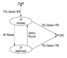
- the UE when the UE first needs to transmit traffic to the data network, it performs a PDU (Packet Data Unit) Session creation procedure.
- PDU Packet Data Unit
- the RAN releases the Control Plane/User Plane between the UE and 5G Core through the AN Release procedure to improve radio resource efficiency.
- the UE's PDU Session is changed to UP Deactivated state through the AN Release procedure.
- a Control Plane/User Plane path is created between the UE and 5G Core through the Service Request procedure.
- the UE's PDU Session is changed to UP activated state through the Service Request procedure.
- the AN Release and Service Request mentioned above occur very frequently and repeatedly. This means that the Service Request procedure occupies a large portion of the entire network, and if the Service Request procedure can be streamlined, the overall network performance can be made more efficient.
- the present invention seeks to propose a new technical solution that can make the UE's Service Request procedure more efficient.
- the technical problem to be solved by the present invention is to realize a new technical method that can make the Service Request procedure more efficient by reducing signaling occurring in the UE's Service Request procedure.
- a session control device includes a confirmation unit that verifies a terminal for activating a path in the User Plane (UP); During the UP path activation procedure for the terminal, specific information related to information storage is transmitted to the access control device, and some signaling is omitted by utilizing the specific information when the access control device performs the UP path activation procedure for the terminal. It includes an information transmission unit that allows it to be done.
- UP User Plane
- the specific information may be delivered using a specific message delivering an N2 PDU Session Resource Setup Request Transfer IE including the UPlink Tunnel information of the UP for the terminal to the access control device.
- the specific information is provided by a first identifier or previous specific information that stores the N2 PDU Session Resource Setup Request Transfer IE including the information constituting the specific information and the uplink tunnel information of the UP as a specific context.
- Identification information indicating a second identifier for deleting a previously stored specific context, and when the first identifier is indicated in the identification information, TAI (Tracking Area Identity) is included in a certain range of units supportable by the UP. ) or second information indicating whether the UP supports all TAIs.
- TAI Track Area Identity
- the specific message is Nsmf_PDUSession_UpdateSMContext Response Message when the UP's path activation procedure is a UE Triggered Service Request procedure, and when the UP's path activation procedure is a NW (Network) Triggered Service Request procedure or a PDU Session Establishment procedure. , Namf_Communication_N1N2MessageTransfer Request Message.
- the information delivery unit may determine whether to deliver the specific information based on availability related to storage of the information previously received from the access control device.
- the partial signaling is a request and response message transmitted and received by the access control device with the session control device to obtain an N2 PDU Session Resource Setup Request Transfer IE including the uplink tunnel information of the UP for the terminal. It can be.
- the information transmission unit confirms changes to the N2 PDU Session Resource Setup Request Transfer IE including the uplink tunnel information of the UP during the UE/RAN Triggered PDU Session Modification procedure or the NW Triggered PDU Session Modification procedure for the terminal.
- the access control device When the specific information indicating the identification information as the second identifier is transmitted to the access control device, the access control device according to the specific information deletes the specific context previously stored by the previous specific information and remains. Allows the process to proceed.
- An access control device includes a context checker that checks whether a specific context previously stored exists in a terminal for activating a path in the User Plane (UP); And when the specific context exists, a control unit that omits some signaling with the session control device using the specific context when performing the UP path activation procedure for the terminal.
- UP User Plane
- the specific context is stored by specific information transmitted from the session control device during the UP path activation procedure previously performed for the terminal, and is stored as a Tracking Area Identity (TAI) in a certain range of units supportable by the UP. ) or second information indicating whether the UP supports all TAIs, and N2 PDU Session Resource Setup Request Transfer IE including Uplink Tunnel information of the UP for the terminal.
- TAI Tracking Area Identity
- N2 PDU Session Resource Setup Request Transfer IE including Uplink Tunnel information of the UP for the terminal.
- the terminal when the control unit determines that the location of the terminal belongs to the TAI according to the first information or the second information in the specific context when performing the UP path activation procedure for the terminal, the terminal For this, the remaining procedures can be performed by reusing the N2 PDU Session Resource Setup Request Transfer IE in the specific context without some signaling to obtain the N2 PDU Session Resource Setup Request Transfer IE including the uplink tunnel information of the UP. there is.
- control unit may delete the specific context and proceed with the remaining procedures. .
- a terminal device includes a request unit that transmits a request for activating a path to a user plane (UP); and a control unit that activates the UP path by controlling the access control device that receives the request;
- the request includes the location of the terminal device, and the access control device stores the location of the terminal device confirmed in the request during the UP path activation procedure previously performed for the terminal device.
- a signaling control method performed in a session control device includes a confirmation step of checking a terminal for activating a path in the User Plane (UP); And, during the UP path activation procedure for the terminal, specific information related to information storage is transmitted to the access control device, so that some signaling can be omitted by utilizing the specific information during the UP path activation procedure for the terminal. It includes the information transfer step.
- UP User Plane
- the specific information is delivered using a specific message that transmits an N2 PDU Session Resource Setup Request Transfer IE including the UPlink Tunnel information of the UP for the terminal to the access control device, and the specific information is, To delete a specific context already stored by a first identifier or previous specific information that stores the N2 PDU Session Resource Setup Request Transfer IE, including information constituting specific information and uplink tunnel information of the UP, as a specific context.
- Identification information in which a second identifier is displayed, and first information that is included when the first identifier is displayed in the identification information and indicates TAI (Tracking Area Identity) in units of a certain range supportable by the UP or the UP It may consist of second information indicating whether all TAIs are supported.
- the specific information is delivered to the access control device using a specific message delivering N2 PDU Session Resource Setup Request Transfer IE including the uplink tunnel information of the UP for the terminal, and the specific message is ,
- the path activation procedure of the UP is a UE Triggered Service Request procedure, it may be a Nsmf_PDUSession_Update_SMContext Response Message, and if the path activation procedure of the UP is a NW Triggered Service Request procedure or a PDU Session Establishment procedure, it may be a Namf_Communication_N1N2MessageTransfer Request Message.
- a signaling control method performed in an access control device includes a context checking step of checking whether a specific context previously stored exists for a terminal for activating a path in the User Plane (UP); And when the specific context exists, a control step of omitting some signaling with the session control device using the specific context when performing the UP path activation procedure for the terminal.
- UP User Plane
- a specific technical configuration that can streamline the Service Request procedure is realized by reducing signaling occurring in the UE's Service Request procedure.
- the present invention has the effect of making overall network performance more efficient in various aspects, such as reducing computing resource consumption for the Service Request procedure and shortening the latency of the UE connecting to the data network.
- Figure 1 is an example diagram showing the life cycle of a PDU session divided by state.
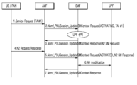
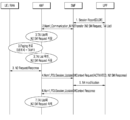
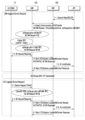
- FIGS 2 and 3 are example diagrams showing the call flow in which the existing Service Request procedure progresses.
- Figure 4 is a block diagram showing the configuration of a session control device, an access control device, and a terminal device according to an embodiment of the present invention.
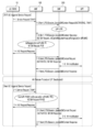
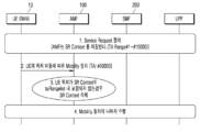
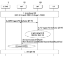
- FIGS 5 and 6 are flow charts showing the Service Request procedure performed by the signaling control method according to an embodiment of the present invention.
- Figures 7 and 8 are flow charts showing an embodiment in which SR (Service Request) Context is deleted by the signaling control method according to the present invention.
- the present invention relates to technology that can make the Service Request procedure of a terminal (UE) more efficient.
- a network structure is defined to support terminals, base stations (access), cores, and servers end to end.
- 5G separates the functions of control signaling and data transmission and reception, and defines a network structure that separates the control signaling function area (Control Plane) and the data transmission and reception function area (User Plane).
- the node of the Control Plane (CP) in 5G is the Access and Mobility Management Function (AMF), which controls access to the wireless section of the terminal, and the PCF (PCF), which manages/controls policies such as terminal information, subscription service information for each terminal, and billing.
- AMF Access and Mobility Management Function
- PCF PCF
- Policy Control Function Policy Control Function
- SMF Session Management Function
- NEF Network Exposure Function
- UDM/AUSF Unified Data Management / Authentication Function
- NRF Network Repository Function
- CHF Network Repository Function
- the User Plane (UP) node is a UPF (User Plane Function) that transmits and receives data between the terminal and servers on an external service network (e.g. the Internet) through a session with the terminal based on the control (interlocking) of the SMF. It can be defined as:
- control node of the control plane and the data node of the user plane can be collectively referred to as a network device (Network Function, NF).
- Network Function Network Function
- the terminal links with the 5G Core to access the data network (e.g. Internet).
- the data network e.g. Internet
- the UE when the UE first needs to transmit traffic to the data network, it performs a PDU (Packet Data Unit) Session creation procedure.
- PDU Packet Data Unit
- the RAN releases the Control Plane/User Plane between the UE and 5G Core through the AN Release procedure to improve radio resource efficiency.
- the UE's PDU Session is changed to UP Deactivated state through the AN Release procedure.
- a Control Plane/User Plane path is created between the UE and 5G Core through the Service Request procedure.
- the UE's PDU Session is changed to UP activated state through the Service Request procedure.
- the UE performs the PDU Session deletion procedure.
- the creation and deletion of a PDU session in the PDU session life cycle occurs when there is a special event such as power on/off of the UE, and AN Release and Service Request occur frequently and repeatedly.
- the proportion of the PDU session creation and deletion procedures among the total procedures is approximately 0.5% each, while the proportions of AN Release and Service Request are each approximately 40%.
- the present invention seeks to propose a new technical solution that can make the UE's Service Request procedure more efficient.
- UP Deactivated To create (activate) a UP path in a state where there is no User Plane (UP) path between the UE and RAN (UP Deactivated), there are UE Triggered Service Request method and Network Triggered Service Request method.
- UP User Plane
- UP Deactivated To create (activate) a UP path in a state where there is no User Plane (UP) path between the UE and RAN (UP Deactivated), there are UE Triggered Service Request method and Network Triggered Service Request method.
- Figure 2 shows the UE Triggered Service Request method
- Figure 3 shows the NW Triggered Service Request method.
- the UE Triggered Service Request procedure is described with reference to Figure 2 as follows.
- the UE If the UE needs to transmit uplink traffic, it requests a Service Request to AMF (via RAN). At this time, the request includes the UE's location information (TAI: Tracking Area Identity).
- TAI Tracking Area Identity
- AMF requests the SMF to select a UPF that supports the corresponding TAI and deliver N2 SM information (tunnel information to receive uplink).
- the SMF selects a UPF based on the corresponding TAI and then transmits an N2 SM Request containing information about the tunnel through which the UPF will receive the uplink to the AMF.
- AMF sends an N2 Request to RAN including the information received from SMF. This creates a path to transmit uplink between UE and 5G Core through RAN. RAN transmits N2 Response (tunnel information to receive downlink) to AMF.
- AMF delivers the information received from RAN to SMF.
- SMF transmits tunnel information for downlink transmission to UPF. This creates a path to transmit downlink between the UE and 5G Core through UPF.
- SMF sends an Update Response to AMF.
- the AMF cannot know the UPF information that can be supported for the UE's location (e.g. TAI#1), so Step.
- AMF must always send Nsmf_PDUSession_UpdateSMContext_Request to SMF to request UPF selection and N2 SM information delivery.
- UPF When UPF receives Downlink Traffic but is in UP Deactivated state, it transmits a Session Report (DLDR, Downlink Data Report) to SMF.
- DLDR Downlink Data Report
- SMF When requesting paging from AMF, SMF can transmit it including N2 SM Request (tunnel information where UPF will receive uplink) and TAI List that UPF can support.
- N2 SM Request tunnel information where UPF will receive uplink
- TAI List that UPF can support.
- AMF stores the received N2 SM Request and TAI List. After paging is completed, AMF checks whether the UE's location (e.g. TAI#1) is within the TAI List that UPF can support, and if it is within the TAI List, sends an N2 Request to the RAN using the N2 SM Request received in Step.2. transmit. This creates a path to transmit uplink between UE and 5G Core through RAN. RAN transmits N2 Response (tunnel information to receive downlink) to AMF.
- TAI#1 the UE's location
- N2 Response tunnel information to receive downlink
- AMF delivers the information received from RAN to SMF.
- SMF transmits tunnel information for downlink transmission to UPF. This creates a path to transmit downlink between the UE and 5G Core through UPF.
- AMF deletes the TAI List and N2 SM Request received in Step.2.
- N2 SM Request and TAI List received in step 2 are valid only for this procedure and have limitations such as not being able to be reused, when managing TAIs that can be supported by UPF as a list, and when TAIs are added due to base station expansion, addition of SMF Configuration is necessary, etc. do.
- the present invention aims to improve the tactical limitations of the existing Service Request procedure and realize a new technical method that can make the Service Request procedure more efficient through a specific configuration that can reduce signaling occurring in the Service Request procedure. do.
- the present invention proposes a session control device and an access control device as NFs that realize the signaling reduction method of the SR procedure, and a terminal device that operates in conjunction with them.
- Figure 4 shows the session control device and the access control device. It shows each configuration of the device and terminal device.
- the session control device 200 of the present invention may be CU-CP, SMF, or S/PGW-C. However, hereinafter, for convenience of explanation, SMF will be mentioned as the session control device 200.
- the session control device 200 of the present invention includes a confirmation unit 210 and an information delivery unit 220.
- All or at least part of the above-mentioned components of the session control device 200 may be implemented in the form of hardware modules or software modules, or may be implemented in the form of a combination of hardware modules and software modules.
- the software module can be understood as, for example, an instruction executed by a processor that controls operations within the session control device 200, and these instructions may be mounted in a memory within the session control device 200. There will be.
- the session control device 200 of the present invention realizes the signaling reduction method of the SR procedure proposed in the present invention through the above-described configuration.
- each configuration in the session control device 200 for realizing this will be described. Let us explain in more detail.
- the confirmation unit 210 is responsible for confirming the terminal 10 for activating the path of the User Plane (UP).
- the “UE for UP path activation” identified in relation to the UE Triggered Service Request procedure corresponds to a UE requesting a Service Request to AMF (via RAN) in the UP Deactivated state without a UP path.
- the “UE for UP path activation” identified in relation to the NW Triggered Service Request procedure corresponds to a UE in the UP Deactivated state to which a Session Report (DLDR, Downlink Data Report) is transmitted from UPF.
- DLDR Downlink Data Report
- the information transmission unit 220 transmits specific information related to information storage to the access control device 100 during the UP path activation procedure for the terminal 10 for UP path activation, and then It is responsible for the function of allowing some signaling to be omitted through the use of the above-mentioned specific information during the UP path activation procedure.
- the UP path activation procedure for the terminal 10 means the Service Request procedure.
- the information transmission unit 220 transmits specific information to the access control device 100 (e.g., AMF) during the Service Request procedure of the terminal 10, and then transmits the specific information during the Service Request procedure of the terminal 10. Utilization allows some signaling to be omitted.
- the access control device 100 e.g., AMF
- the specific information is defined as being delivered using a specific message that transmits the N2 PDU Session Resource Setup Request Transfer IE including UP's Uplink Tunnel information for the terminal 10 to the access control device 100 (e.g., AMF). do.
- the specific message at this time may be the Nsmf_PDUSession_UpdateSMContext Response Message when the Service Request procedure of this UP is a UE Triggered Service Request procedure.
- the information transmission unit 220 transmits the N2 PDU Session Resource Setup Request Transfer IE including the UPlink Tunnel information of the UP during the UE Triggered Service Request procedure according to the Service Request of the terminal 10 to the access control device 100, e.g. By using additional fields in the PDUSession_UpdateSMContext Response Message delivered to AMF), specific information can be delivered to the access control device 100 (e.g. AMF).
- the specific message at this time may be Namf_Communication_N1N2MessageTransfer Request Message if the Service Request procedure of this UP is a NW Triggered Service Request procedure or a PDU Session Establishment procedure.
- the information transmission unit 220 transmits the N2 including the UPlink Tunnel information of the UP during the NW Triggered Service Request procedure or PDU Session Establishment procedure for the terminal 10 according to the Report (DLDR, Downlink Data Report) from the UPF.
- the Report DLDR, Downlink Data Report
- the information transmission unit 220 transmits the N2 including the UPlink Tunnel information of the UP during the NW Triggered Service Request procedure or PDU Session Establishment procedure for the terminal 10 according to the Report (DLDR, Downlink Data Report) from the UPF.
- the access control device 100, e.g., AMF
- specific information can be transmitted together to the access control device (100, e.g., AMF).
- the specific information related to information storage includes a first identifier or a previous specific information that stores the N2 PDU Session Resource Setup Request Transfer IE, including the information constituting the specific information and the UPlink Tunnel information, as a specific context.
- Identification information indicating a second identifier for deleting a specific context previously stored by the information, and when the first identifier is indicated in the identification information, TAI (TAI) in units of a certain range that can be supported by the UP It can be defined as consisting of first information indicating Tracking Area Identity or second information indicating whether the UP supports all TAIs.
- 'specific information' to be transmitted to the access control device (100, e.g., AMF) and 'specific information' received by the access control device (100, e.g., AMF) are stored (Cache).
- ‘Specific context’ as information to be used can be newly defined.
- Cache required information and "SR Context” can be newly defined as described above, and first, “Cache required information” can be defined as shown in Table 1 below.
- the 'specific information' defined in the present invention is identification information "n2CacheRequired” in which True as the first identifier or False as the second identifier, and n2CacheRequired When is True, it is composed of "taiRangeList” as first information or "allPLMN" as second information.
- taiRangeList means transmitting a plurality of “taiRange” representing TAI in units of a certain range in the form of an array. Details of taiRange may include PLMN and TacRange.
- This taiRange is defined by specifying TAI in units of a certain range using start to end values, so if taiRange is specified/registered for each service area, additional work is required in SMF as a new base station is added. You may not.
- allPLMN means the case where UPF supports all TAIs.
- the access control device 100 e.g., AMF
- the access control device 100 stores (cache) taiRangeList as an SR Context
- the access control device 100 e.g., TAI If #1
- TAI If #1 belongs to the taiRangeList that is being cached, some signaling can be omitted in this Service Request procedure.
- the access control device 100 (e.g., AMF) stores (cache) allPLMN as an SR Context
- the access control device 100 e.g., AMF
- caches the location of the corresponding terminal 10 e.g., TAI Regardless of #1
- some signaling can be omitted in this Service Request procedure.
- some signaling omitted in the Service Request procedure is performed by the access control device (100, e.g., AMF) in order to obtain the N2 PDU Session Resource Setup Request Transfer IE including UP's Uplink Tunnel information for the terminal (10). It may refer to request and response messages transmitted and received with the control device 200 (eg, SMF).
- the access control device 100 obtains the N2 PDU Session Resource Setup Request Transfer IE including UP's Uplink Tunnel information for the terminal 10 when performing the Service Request procedure for the terminal 10.
- the information transmission unit 220 determines whether the information stored previously received from the access control device 100 (eg, AMF) is available (hereinafter referred to as SR Context Cache availability). It is possible to determine whether specific information, that is, cache-required information, is delivered.
- AMF access control device 100
- the access control device (100, e.g., AMF) can transmit information indicating whether it can cache the SR Context to the session control device (200, e.g., SMF), and the information is sent to the Nsmf_PDUSession_CreateSMContext Request.
- the session control device 200, e.g., SMF
- the information is sent to the Nsmf_PDUSession_CreateSMContext Request.
- it can be delivered using an additional field in the Nsmf_PDUSession_UpdateSMContext Request.
- the information delivery unit 220 of the session control device 200 (e.g., SMF), based on the availability of the SR Context Cache previously received from the access control device 100 (e.g., AMF), , e.g., during the (UE Triggered or NW UE Triggered) Service Request procedure of the terminal 10 interoperating with the AMF), the N2 PDU Session Resource Setup Request Transfer IE including UPlink Tunnel information is transmitted to the access control device 100, e.g. AMF. ) can be used to determine whether to transmit cache required information together.
- the information transmission unit 220 transmits the N2 PDU including the UPlink Tunnel information of the UP during the UE/RAN Triggered PDU Session Modification procedure or the NW Triggered PDU Session Modification procedure for the terminal 10.
- Session Resource Setup Request Transfer When confirming a change to IE, specific information (Cache required information) indicating the identification information (n2CacheRequired) as the second identifier (False) can be transmitted to the access control device 100 (e.g. AMF). .
- N2 SM Request a change in information of such N2 SM information
- the SR Context previously cached in the access control device 100 e.g. AMF
- n2CacheRequired False
- the access control device 100 of the present invention may be an AMF.
- the access control device 100 of the present invention includes a context check unit 110 and a control unit 120.
- All or at least part of the above-mentioned components of the access control device 100 may be implemented in the form of hardware modules or software modules, or may be implemented in the form of a combination of hardware modules and software modules.
- the software module can be understood as, for example, an instruction executed by a processor that controls operations within the access control device 100, and these instructions may be mounted in a memory within the access control device 100. There will be.
- the access control device 100 of the present invention realizes the signaling reduction method of the SR procedure proposed in the present invention through the above-described configuration.
- each configuration in the access control device 100 for realizing this will be described. Let us explain in more detail.
- the context check unit 110 is responsible for checking whether a specific context previously stored exists in the terminal for activating the path of the User Plane (UP).
- UP User Plane
- the “terminal for UP path activation” is a terminal for which a Service Request procedure (UE Triggered or NW Triggered) is performed in the UP Deactivated state, and will be described with reference to the above-described terminal 10.
- UE Triggered or NW Triggered Service Request procedure
- the specific context refers to the SR Context stored (cache) by specific information transmitted from the session control device (200, SMF) of the present invention during the previous Service Request procedure, that is, "Cache required information”. do.
- the session control device 200 of the present invention accesses the N2 PDU Session Resource Setup Request Transfer IE including UPlink Tunnel information during the (UE Triggered or NW UE Triggered) Service Request procedure of the terminal 10.
- Cache required information can also be transmitted using a message transmitted to the control device 100 (eg, AMF).
- the access control device 100 (e.g., AMF) of the present invention stores (cache) the information according to the cache required information when cache required information exists in the message transmitted from the session control device 200, and
- the information stored (cache) corresponds to the SR Context.
- the SR Context is "taiRangeList" as first information indicating TAI in units of a certain range supportable in the UP, or second information indicating whether all TAIs are supported in the UP.
- allPLMN as information
- n2CacheRequired true in the Cache required information
- SR Context a mapping between SR Context and SR Context.
- the context checker 110 determines that, for the terminal 10 in which a (UE Triggered or NW Triggered) Service Request procedure is in progress, there is an SR Context previously stored (cache) by the present invention during the previously performed Service Request procedure. Make sure you do it.
- control unit 120 activates the corresponding SR when performing the UP path activation procedure (Service Request procedure) for the terminal 10. It is responsible for the function of omitting and proceeding with some signaling with the session control device (200, e.g., SMF) using context.
- UP path activation procedure Service Request procedure
- the control unit 120 collects the first information in the SR Context that is already cached by the location of the terminal 10 (e.g., TAI#1). It is determined whether it belongs to TAI according to "taiRangeList" as or "allPLMN" as second information.
- the control unit 120 determines whether the location of the corresponding terminal 10 (e.g. TAI #1) belongs to the stored (Cache) taiRangeList. It is done.
- control unit 120 determines that the terminal 10 belongs to allPLMN regardless of its location (e.g., TAI#1).
- control unit 120 determines that the location of the corresponding terminal 10 (e.g. TAI #1) belongs to taiRangeList (or allPLMN) in the SR Context, N2 including Uplink Tunnel information of UP in this Service Request procedure. Without some of the signaling above to obtain the PDU Session Resource Setup Request Transfer IE, the remaining procedures can be performed by reusing the N2 PDU Session Resource Setup Request Transfer IE, which includes the Uplink Tunnel information of the UP in the SR Context.
- N2 SM information N2 SM Request
- the session control device 200, e.g. SMF
- control unit 120 determines the location of the terminal 10 (e.g., TAI) according to the first information in the SR Context, that is, taiRangeList, during a mobility-related procedure for the terminal 10. If it is determined that it does not belong to TAI, you can delete the relevant SR Context and proceed with the remaining procedures.
- TAI the location of the terminal 10
- the location (e.g., TAI) may change depending on the movement (e.g., handover, etc.) of the terminal 10, and in the present invention, this causes the location (e.g., TAI) of the terminal 10 to be stored in taiRangeList in the SR Context. If it is determined that it does not belong to the corresponding TAI, the previously cached SR Context is no longer valid, so the SR Context is deleted.
- the access control device 100 deletes the SR Context for the terminal 10 that has already been stored (cache) according to the previous Cache required information, and You can proceed with the remaining mobility-related procedures in progress.
- the terminal device 10 of the present invention includes a request unit 11 and a control unit 12.
- All or at least part of the above-described components of the terminal device 10 may be implemented in the form of hardware modules, software modules, or a combination of hardware modules and software modules.
- the software module can be understood as, for example, an instruction executed by a processor that controls operations within the terminal device 10, and such instructions may be mounted in a memory within the terminal device 10. .
- the terminal device 10 of the present invention supports the signaling reduction method of the SR procedure proposed in the present invention through the above-described configuration, and below, each configuration in the terminal device 10 to realize this will be described in more detail. It will be explained as follows.
- the request unit 11 is responsible for transmitting a request for activating the UP path.
- UP path activation means UP activated state
- a request for UP path activation means Service Request.
- the request unit 11 can transmit a request for UP activation, that is, a Service Request, to the AMF (via RAN).
- the control unit 12 activates the UP path by controlling the access control device 100 (eg, AMF) that has received the request, that is, the Service Request, and the terminal device 10 can be in the UP activated state. .
- the access control device 100 eg, AMF
- the request that is, the Service Request
- the request unit 11 includes the location of the terminal device 10 (eg, TAI #1).
- the access control device 100 (e.g., AMF) that has received the Service Request transfers information to the terminal device 10 based on the location of the terminal device 10 (e.g., TAI#1) confirmed in the Service Request.
- the specific context SR Context
- some signaling can be omitted during the UP Service Request procedure.
- the access control device 100 e.g., AMF
- the location of the terminal device 10 confirmed in the Service Request when the Service Request procedure for the terminal 10 is performed. If (e.g. TAI#1) belongs to the taiRangeList being cached, some signaling during this Service Request procedure can be omitted.
- the signaling control method performed by the device, and the terminal device, the Service Request procedure can be streamlined by reducing signaling occurring in the UE's Service Request procedure.
- the present invention realizes a new technical method that can streamline the UE's Service Request procedure, thereby reducing the consumption of computing resources for the Service Request procedure and shortening the latency for the UE to connect to the data network, thereby improving the overall overall performance in various aspects.
- the effect of making network performance more efficient can be derived.
- Figure 5 shows the Service Request procedure, particularly the UE Triggered Service Request procedure, performed by the signaling control method according to an embodiment of the present invention.
- the initial Service Request procedure (First UE triggered Service Request) for the terminal 10 is first described as follows.
- the UE (10) When the UE (10) needs to transmit uplink traffic, it requests a Service Request from the AMF (100) (via RAN). At this time, the request includes the location of the UE 10 (e.g. TAI#1).
- AMF requests SMF (200) to select a UPF that supports the corresponding TAI (e.g. TAI#1) and deliver N2 SM information (tunnel information to receive uplink).
- TAI e.g. TAI#1
- N2 SM information to receive uplink
- the SMF (200) selects a UPF based on the corresponding TAI (e.g. TAI#1) and then transmits an N2 SM Request including Tunnel information through which the UPF will receive the uplink to the AMF (100), which can be supported by the selected UPF.
- TAI#1 e.g. TAI#1
- N2 SM Request including Tunnel information through which the UPF will receive the uplink to the AMF (100), which can be supported by the selected UPF.
- AMF (100) stores N2 SM Request and taiRangeList (or allPLMN) in Cache as "SR Context" according to "Cache required information” and transmits N2 Request to RAN including information received from SMF (200). This creates a path to transmit uplink between UE (10) and 5G Core through RAN. RAN delivers N2 Response (tunnel information to receive downlink) to AMF (100).
- AMF (100) transfers information received from RAN to SMF (200).
- the SMF (200) transmits tunnel information for downlink transmission to the UPF. This creates a path to transmit downlink between the UE (10) and the 5G Core through UPF.
- SMF (200) transmits an Update Response to AMF (100).
- the SMF (200) transmits “Cache required information” to the AMF (100) to enable the AMF (100) to create “SR Context” By storing it, it can be utilized (reused) to omit some signaling when proceeding with the Service Request procedure for the UE (10) later.
- the UE (10) When the UE (10) needs to transmit uplink traffic, it requests a Service Request from the AMF (100) (via RAN). At this time, the request includes the location of the UE 10 (e.g. TAI#1). TAI may change depending on the location of the UE (10).
- AMF (100) checks the taiRangeList stored in the Cache and reuses the N2 SM Request if the location of the UE (10) (e.g. TAI#1) is within the taiRangeList (in the case of allPLMN, the N2 SM Request is reused without TAI confirmation) do).
- N2 SM Request information can be transmitted to RAN without 1-2 or 1-3. This creates a path to transmit uplink between UE (10) and 5G Core through RAN. RAN delivers N2 Response (tunnel information to receive downlink) to AMF (100).
- AMF (100) transmits information received from RAN to SMF (200).
- the SMF (200) transmits tunnel information for downlink transmission to the UPF. This creates a path to transmit downlink between the UE (10) and the 5G Core through UPF.
- SMF (200) transmits an Update Response to AMF (100).
- the AMF cannot know the UPF information that can be supported for the location of the UE (10) (e.g. TAI #1), so it must always send Nsmf_PDUSession_UpdateSMContext_Request to the SMF to request UPF selection and delivery of N2 SM information. did.
- Figure 6 shows the Service Request procedure, particularly the NW Triggered Service Request procedure, performed by the signaling control method according to an embodiment of the present invention.
- the UPF When the UPF receives downlink traffic but is in the UP Deactivated state, it transmits a Session Report (DLDR, Downlink Data Report) to the SMF (200).
- DLDR Downlink Data Report
- AMF (100) stores N2 SM Request and taiRangeList (or allPLMN) in the cache as “SR Context” according to “Cache required information”. After paging is completed, the AMF 100 checks whether the location of the UE 10 (e.g. TAI#1) is within the taiRangeList that UPF can support, and if it is within the taiRangeList, Step.
- the N2 SM information received in 1-2 is reused to send an N2 Request to the RAN (in the case of allPLMN, the N2 SM Request is reused without TAI confirmation.) This results in uplink between the UE (10) and the 5G Core through the RAN.
- a path to transmit is created.
- RAN transmits N2 Response (tunnel information to receive downlink) to AMF.
- AMF (100) transmits information received from RAN to SMF (200).
- the SMF (200) transmits tunnel information for downlink transmission to the UPF. This creates a path to transmit downlink between the UE (10) and the 5G Core through UPF.
- SMF (200) transmits an Update Response to AMF (100).
- the SMF (200) transmits “Cache required information” to the AMF (100) to cause the AMF (100) to store “SR Context”, and then the UE It can be utilized (reused) to omit some signaling when proceeding with the Service Request procedure for (10).
- the UE (10) When the UE (10) needs to transmit uplink traffic, it requests a Service Request from the AMF (100) (via RAN). At this time, the request includes the location of the UE 10 (e.g. TAI#1). TAI may change depending on the location of the UE (10).
- AMF (100) checks the taiRangeList stored in the Cache and reuses the N2 SM Request if the location of the UE (10) (e.g. TAI#1) is within the taiRangeList (in the case of allPLMN, the N2 SM Request is reused without TAI confirmation) do). That is, the AMF 100 performs Step 5 of FIG. 5 described above.
- N2 SM Request information can be transmitted to RAN without 1-2 or 1-3. This creates a path to transmit uplink between UE (10) and 5G Core through RAN. RAN delivers N2 Response (tunnel information to receive downlink) to AMF (100).
- AMF (100) transmits information received from RAN to SMF (200).
- the SMF (200) transmits tunnel information for downlink transmission to the UPF. This creates a path to transmit downlink between the UE (10) and the 5G Core through UPF.
- SMF (200) transmits an Update Response to AMF (100).
- the subsequent UE Transactions between AMF (100) and SMF (200) can be reduced by omitting some signaling when proceeding with the Service Request procedure for (10).
- the SMF (200) instead of using a TAI List listing individual TAIs, the SMF (200) transmits taiRangeList to the AMF (100), and the AMF (100) utilizes (r recipients) the taiRangeList. ), there is even an effect of omitting/reducing signaling in the Service Request procedure.
- taiRangeList is used, so when TAIs are added due to base station expansion, it is unnecessary to add SMF Configuration, and the N2 SM Request is re-enabled. Due to the fact that it can be used, not only can the Service Request procedure be streamlined, but overall network performance can be made more efficient in various aspects.
- Figure 7 shows the flow of an embodiment in which SR Context is deleted by the signaling control method according to the present invention, particularly an embodiment in which AMF is proactively deleted.
- UE/RAN may perform mobility-related procedures (e.g., handover) with the AMF (100) according to the movement of the UE (10).
- mobility-related procedures e.g., handover
- the AMF (100) checks whether the location of the UE (10) received in the mobility-related procedure is included in the taiRangeList in the SR Context, and if not, deletes the SR Context. If included in taiRangeList, the SR Context is not deleted.
- Figure 8 shows the flow of an embodiment in which SR Context is deleted by the signaling control method according to the present invention, particularly deletion by SMF.
- the UE/RAN performs a modification procedure (UE/RAN Triggered PDU Session Modification procedure) when the PDU session needs to be changed.
- UE/RAN Triggered PDU Session Modification procedure UE/RAN Triggered PDU Session Modification procedure
- N2 SM information may change, such as QoS changes.
- PCF performs a modification procedure (NW Triggered PDU Session Modification procedure) when the PDU session needs to be changed.
- N2 SM information may change, such as QoS changes.
- SMF (200) is Step. It is possible to detect whether N2 SM information has been changed by 2a or 2b.
- the signaling control method and data processing method may be implemented in the form of program instructions that can be executed through various computer means and recorded on a computer-readable medium.
- the computer-readable medium may include program instructions, data files, data structures, etc., singly or in combination.
- Program instructions recorded on the medium may be specially designed and constructed for the present invention or may be known and usable by those skilled in the art of computer software. Examples of computer-readable recording media include magnetic media such as hard disks, floppy disks, and magnetic tapes, optical media such as CD-ROMs and DVDs, and magnetic media such as floptical disks.
- optical media magnetic-optical media
- hardware devices specifically configured to store and execute program instructions, such as ROM, RAM, flash memory, etc.
- program instructions include machine language code, such as that produced by a compiler, as well as high-level language code that can be executed by a computer using an interpreter, etc.
- the hardware devices described above may be configured to operate as one or more software modules to perform the operations of the present invention, and vice versa.
Landscapes
- Engineering & Computer Science (AREA)
- Computer Networks & Wireless Communication (AREA)
- Signal Processing (AREA)
- Databases & Information Systems (AREA)
- Mobile Radio Communication Systems (AREA)
Abstract
Description

Claims (15)
- User Plane(UP)의 경로 활성화를 위한 단말을 확인하는 확인부; 및상기 단말에 대한 UP의 경로 활성화 절차 중에 정보 저장과 관련된 특정 정보를 액세스 제어 장치로 전달하여, 상기 액세스 제어 장치에서 상기 단말에 대한 UP의 경로 활성화 절차 진행 시 상기 특정 정보 활용을 통해 일부 시그널링이 생략될 수 있게 하는 정보 전달부를 포함하는 것을 특징으로 하는 세션 제어 장치.
- 제 1 항에 있어서,상기 특정 정보는,상기 단말에 대한 상기 UP의 Uplink Tunnel 정보를 포함한 N2 PDU Session Resource Setup Request Transfer IE를 상기 액세스 제어 장치로 전달하는 특정 메시지를 이용하여, 전달되는 것을 특징으로 하는 세션 제어 장치.
- 제 2 항에 있어서,상기 특정 정보는,상기 특정 정보를 구성하는 정보 및 상기 N2 PDU Session Resource Setup Request Transfer IE를 특정 컨텍스트로서 저장하도록 하는 제1 식별자 또는 이전의 특정 정보에 의해 기 저장하고 있는 특정 컨텍스트를 삭제하도록 하는 제2 식별자가 표시되는 식별 정보와,상기 식별 정보에 상기 제1 식별자가 표시된 경우에 포함되어, 상기 UP에서 지원 가능한 일정 범위의 단위로 TAI(Tracking Area Identity)를 나타내는 제1 정보 또는 상기 UP에서 모든 TAI를 지원하는지 여부를 나타내는 제2 정보로 구성되는 것을 특징으로 하는 것을 특징으로 하는 세션 제어 장치.
- 제 2 항에 있어서,상기 특정 메시지는,상기 UP의 경로 활성화 절차가 UE Triggered Service Request 절차인 경우, Nsmf_PDUSession_UpdateSMContext Response Message 이며,상기 UP의 경로 활성화 절차가 NW Triggered Service Request 절차 또는 PDU Session Establishment 절차인 경우, Namf_Communication_N1N2MessageTransfer Request Message인 것을 특징으로 하는 세션 제어 장치.
- 제 1 항에 있어서,상기 정보 전달부는,상기 액세스 제어 장치로부터 기 전달 받은 상기 정보 저장과 관련된 가능 여부를 근거로, 상기 특정 정보의 전달 여부를 판단하는 것을 특징으로 하는 세션 제어 장치.
- 제 2 항에 있어서,상기 일부 시그널링은,상기 단말에 대하여 상기 N2 PDU Session Resource Setup Request Transfer IE를 획득하기 위해, 상기 액세스 제어 장치가 상기 세션 제어 장치와 송수신하는 요청 및 응답 메시지인 것을 특징으로 하는 세션 제어 장치.
- 제 2 항에 있어서,상기 정보 전달부는,상기 단말에 대한 UE/RAN Triggered PDU Session Modification 절차 또는 NW Triggered PDU Session Modification 절차 중에, 상기 N2 PDU Session Resource Setup Request Transfer IE에 대한 변경 확인 시 상기 식별 정보를 상기 제2 식별자로 표시한 특정 정보를 상기 액세스 제어 장치로 전달하여,상기 특정 정보에 따라 상기 액세스 제어 장치가, 이전의 특정 정보에 의해 기 저장하고 있는 특정 컨텍스트를 삭제하고 나머지 절차를 진행할 수 있게 하는 것을 특징으로 하는 세션 제어 장치.
- User Plane(UP)의 경로 활성화를 위한 단말에 대하여, 기 저장하고 있는 특정 컨텍스트가 존재하는지 확인하는 컨텍스트확인부; 및상기 특정 컨텍스트가 존재하는 경우, 상기 단말에 대한 상기 UP의 경로 활성화 절차 진행 시 상기 특정 컨텍스트를 이용하여 세션 제어 장치와의 일부 시그널링을 생략하고 진행하는 제어부를 포함하는 것을 특징으로 하는 액세스 제어 장치.
- 제 8 항에 있어서,상기 특정 컨텍스트는,상기 단말에 대하여 이전 진행된 상기 UP의 경로 활성화 절차 중에 상기 세션 제어 장치로부터 전달되는 특정 정보에 의해 저장되며,상기 UP에서 지원 가능한 일정 범위의 단위로 TAI(Tracking Area Identity)를 나타내는 제1 정보 또는 상기 UP에서 모든 TAI를 지원하는지 여부를 나타내는 제2 정보와, 상기 단말에 대한 상기 UP의 Uplink Tunnel 정보를 포함한 N2 PDU Session Resource Setup Request Transfer IE로 정의되는 것을 특징으로 하는 액세스 제어 장치.
- 제 9 항에 있어서,상기 제어부는,상기 액세스 제어 장치가 특정 컨텍스트의 저장 가능 여부를 상기 세션 제어 장치로 전달하여, 상기 세션 제어 장치가 상기 특정 정보의 전달 여부를 판단할 수 있게 하는 것을 특징으로 하는 액세스 제어 장치.
- 제 8 항에 있어서,상기 제어부는,상기 단말에 대한 상기 UP의 경로 활성화 절차 진행 시, 상기 단말의 위치가 상기 특정 컨텍스트 내 상기 제1 정보 또는 상기 제2 정보에 따른 TAI에 속한다고 판단되는 경우,상기 단말에 대하여, 상기 UP의 업링크 터널 정보를 포함한 N2 PDU Session Resource Setup Request Transfer IE 획득을 위한 상기 일부 시그널링 없이, 상기 특정 컨텍스트 내 상기 UP의 업링크 터널 정보를 포함한 N2 PDU Session Resource Setup Request Transfer IE를 재 사용하여 나머지 절차를 진행하는 것을 특징으로 하는 액세스 제어 장치.
- 제 8 항에 있어서,상기 제어부는,상기 단말에 대한 Mobility 관련 절차 중에, 상기 단말의 위치가 상기 특정 컨텍스트 내 상기 제1 정보에 따른 TAI에 속하지 않는다고 판단되면, 상기 특정 컨텍스트를 삭제하고 나머지 절차를 진행하는 것을 특징으로 하는 액세스 제어 장치.
- 단말장치에 있어서,User Plane(UP)의 경로 활성화를 위한 요청을 전달하는 요청부; 및상기 요청을 전달 받은 액세스 제어 장치의 제어에 의해, 상기 UP의 경로를 활성화하게 되는 제어부를 포함하며;상기 요청에는 상기 단말장치의 위치가 포함되며,상기 액세스 제어 장치는, 상기 요청에서 확인되는 상기 단말장치의 위치를 근거로, 상기 단말장치에 대하여 이전에 진행한 UP의 경로 활성화 절차 중에 기 저장하고 있던 특정 컨텍스트를 재 사용하여 상기 UP의 경로 활성화 절차 중 일부 시그널링을 생략하고 진행하는 것을 특징으로 하는 단말장치.
- 세션 제어 장치에서 수행되는 시그널링 제어 방법에 있어서,User Plane(UP)의 경로 활성화를 위한 단말을 확인하는 확인단계; 및상기 단말에 대한 UP의 경로 활성화 절차 중에 정보 저장과 관련된 특정 정보를 액세스 제어 장치로 전달하여, 이후 상기 단말에 대한 UP의 경로 활성화 절차 진행 시 상기 특정 정보 활용을 통해 일부 시그널링이 생략될 수 있게 하는 정보 전달단계를 포함하는 것을 특징으로 하는 시그널링 제어 방법.
- 액세스 제어 장치에서 수행되는 시그널링 제어 방법에 있어서,User Plane(UP)의 경로 활성화를 위한 단말에 대하여, 기 저장하고 있는 특정 컨텍스트가 존재하는지 확인하는 컨텍스트확인단계; 및상기 특정 컨텍스트가 존재하는 경우, 상기 단말에 대한 상기 UP의 경로 활성화 절차 진행 시 상기 특정 컨텍스트를 이용하여 세션 제어 장치와의 일부 시그널링을 생략하고 진행하는 제어단계를 포함하는 것을 특징으로 하는 시그널링 제어 방법.
Priority Applications (2)
| Application Number | Priority Date | Filing Date | Title |
|---|---|---|---|
| CN202280097509.5A CN119422434A (zh) | 2022-06-28 | 2022-10-17 | 会话控制装置、接入控制装置和由装置执行的信令控制方法、以及终端装置 |
| US18/871,869 US20250358709A1 (en) | 2022-06-28 | 2022-10-17 | Session control device, access control device and signaling control method performed by device, and terminal device |
Applications Claiming Priority (2)
| Application Number | Priority Date | Filing Date | Title |
|---|---|---|---|
| KR1020220078933A KR102726281B1 (ko) | 2022-06-28 | 2022-06-28 | 세션 제어 장치 및 액세스 제어 장치와, 그 장치에서 수행되는 시그널링 제어 방법, 단말장치 |
| KR10-2022-0078933 | 2022-06-28 |
Publications (1)
| Publication Number | Publication Date |
|---|---|
| WO2024005268A1 true WO2024005268A1 (ko) | 2024-01-04 |
Family
ID=89380818
Family Applications (1)
| Application Number | Title | Priority Date | Filing Date |
|---|---|---|---|
| PCT/KR2022/015747 Ceased WO2024005268A1 (ko) | 2022-06-28 | 2022-10-17 | 세션 제어 장치 및 액세스 제어 장치와, 그 장치에서 수행되는 시그널링 제어 방법, 단말장치 |
Country Status (4)
| Country | Link |
|---|---|
| US (1) | US20250358709A1 (ko) |
| KR (1) | KR102726281B1 (ko) |
| CN (1) | CN119422434A (ko) |
| WO (1) | WO2024005268A1 (ko) |
Family Cites Families (1)
| Publication number | Priority date | Publication date | Assignee | Title |
|---|---|---|---|---|
| KR20220009274A (ko) * | 2020-07-15 | 2022-01-24 | 에스케이텔레콤 주식회사 | 네트워크 장치 및 그 장치에서 수행되는 시그널링 처리방법 |
-
2022
- 2022-06-28 KR KR1020220078933A patent/KR102726281B1/ko active Active
- 2022-10-17 WO PCT/KR2022/015747 patent/WO2024005268A1/ko not_active Ceased
- 2022-10-17 US US18/871,869 patent/US20250358709A1/en active Pending
- 2022-10-17 CN CN202280097509.5A patent/CN119422434A/zh active Pending
Non-Patent Citations (5)
| Title |
|---|
| "3rd Generation Partnership Project; Technical Specification Group Radio Access Network; NG-RAN; NG Application Protocol (NGAP) (Release 17)", 3GPP TS 38.413, no. V17.1.0, 23 June 2022 (2022-06-23), pages 1 - 570, XP052183200 * |
| "3rd Generation Partnership Project; Technical Specification Group Services and System Aspects; Procedures for the 5G System (5GS); Stage 2 (Release 17)", 3GPP TS 23.502, no. V17.5.0, 15 June 2022 (2022-06-15), pages 1 - 744, XP052182883 * |
| HUAWEI: "SMF URI", 3GPP TSG-CT WG4 MEETING #108-E, C4-221305, 9 February 2022 (2022-02-09), XP052105199 * |
| NOKIA, NOKIA SHANGHAI BELL, ERICSSON: "Notification enhancement with additional filtering", 3GPP TSG-CT WG4 MEETING #106-E, C4-215361, 14 October 2021 (2021-10-14), XP052061013 * |
| NOKIA, NOKIA SHANGHAI BELL: "Support of different slices over different Non 3GPP access", 3GPP TSG-SA WG2 MEETING #143E, S2-2100067, 18 February 2021 (2021-02-18), XP052172425 * |
Also Published As
| Publication number | Publication date |
|---|---|
| KR20240001959A (ko) | 2024-01-04 |
| KR102726281B1 (ko) | 2024-11-04 |
| CN119422434A (zh) | 2025-02-11 |
| US20250358709A1 (en) | 2025-11-20 |
Similar Documents
| Publication | Publication Date | Title |
|---|---|---|
| WO2021010693A1 (en) | Method and apparatus for identifying user in ran communication system | |
| WO2016186416A1 (en) | Method and device for supporting paging optimization | |
| WO2017030399A1 (en) | Ue access method and apparatus | |
| WO2011142567A2 (en) | Handover method supporting terminal mobility | |
| WO2019160278A1 (ko) | Ma pdu 세션의 수립을 처리하는 방안 그리고 amf 노드 및 smf 노드 | |
| WO2014104705A1 (en) | Method and system for supporting fast recovery of user equipment | |
| WO2014098405A1 (en) | Methods, systems and devices for small cell communications | |
| WO2018128477A1 (en) | Method and apparatus for data transport control between wireless network systems | |
| WO2013051845A2 (ko) | 이동 통신 시스템에서 사용자 단말의 접속 제어 방법 및 장치 | |
| WO2022177286A1 (en) | Improvements in and relating to the operation of a user equipment and a telecommunication network | |
| WO2018038490A1 (ko) | 무선 통신 네트워크에서 지역별 데이터 네트워크 구성을 위한 방법 및 시스템 | |
| WO2012138110A2 (en) | A method for guaranteeing establishment of local ip access correctly | |
| EP2468035A2 (en) | Server for control plane at mobile communication network and method for controlling sipto based session | |
| WO2013005992A2 (en) | Method for avoiding handover failure | |
| WO2021091307A1 (ko) | 무선 통신 시스템에서 mbs 서비스 제공에 대한 mbs 서비스 세션의 설정을 위한 장치 및 방법 | |
| WO2018030861A1 (en) | Method for performing light connection control on user equipment and corresponding equipment | |
| WO2022086225A1 (en) | A method for supporting handover | |
| WO2020067849A1 (ko) | 저전력 모드를 사용하는 iot 단말의 연결성을 관리하는 방법 및 장치 | |
| WO2021162395A1 (en) | Method and apparatus for network security | |
| WO2009134064A2 (en) | Method and device to support interworking between 3g system and sae system | |
| WO2023022403A1 (ko) | 무선 이동 통신 시스템에서 rrc_inactive 상태의 단말이 데이터를 송수신하는 방법 및 장치. | |
| WO2021154040A1 (en) | Method and apparatus for recovery from fallback for cellular internet of things device | |
| WO2015020488A1 (ko) | 인증 정보를 얻는 방법 및 장치 | |
| WO2022225315A1 (en) | Method and device for notifying mbs state | |
| WO2022086123A1 (en) | Method and equipment for multicast transmission |
Legal Events
| Date | Code | Title | Description |
|---|---|---|---|
| 121 | Ep: the epo has been informed by wipo that ep was designated in this application |
Ref document number: 22949559 Country of ref document: EP Kind code of ref document: A1 |
|
| WWE | Wipo information: entry into national phase |
Ref document number: 18871869 Country of ref document: US |
|
| WWE | Wipo information: entry into national phase |
Ref document number: 202280097509.5 Country of ref document: CN |
|
| NENP | Non-entry into the national phase |
Ref country code: DE |
|
| WWP | Wipo information: published in national office |
Ref document number: 202280097509.5 Country of ref document: CN |
|
| 122 | Ep: pct application non-entry in european phase |
Ref document number: 22949559 Country of ref document: EP Kind code of ref document: A1 |
|
| WWP | Wipo information: published in national office |
Ref document number: 18871869 Country of ref document: US |