WO2024005182A1 - 作業車両の経路計画生成システム、作業車両の経路計画生成方法 - Google Patents
作業車両の経路計画生成システム、作業車両の経路計画生成方法 Download PDFInfo
- Publication number
- WO2024005182A1 WO2024005182A1 PCT/JP2023/024347 JP2023024347W WO2024005182A1 WO 2024005182 A1 WO2024005182 A1 WO 2024005182A1 JP 2023024347 W JP2023024347 W JP 2023024347W WO 2024005182 A1 WO2024005182 A1 WO 2024005182A1
- Authority
- WO
- WIPO (PCT)
- Prior art keywords
- work vehicle
- work
- route
- route plan
- plan generation
- Prior art date
- Legal status (The legal status is an assumption and is not a legal conclusion. Google has not performed a legal analysis and makes no representation as to the accuracy of the status listed.)
- Ceased
Links
Images






Classifications
-
- E—FIXED CONSTRUCTIONS
- E02—HYDRAULIC ENGINEERING; FOUNDATIONS; SOIL SHIFTING
- E02F—DREDGING; SOIL-SHIFTING
- E02F9/00—Component parts of dredgers or soil-shifting machines, not restricted to one of the kinds covered by groups E02F3/00 - E02F7/00
- E02F9/26—Indicating devices
- E02F9/261—Surveying the work-site to be treated
- E02F9/262—Surveying the work-site to be treated with follow-up actions to control the work tool, e.g. controller
-
- E—FIXED CONSTRUCTIONS
- E02—HYDRAULIC ENGINEERING; FOUNDATIONS; SOIL SHIFTING
- E02F—DREDGING; SOIL-SHIFTING
- E02F9/00—Component parts of dredgers or soil-shifting machines, not restricted to one of the kinds covered by groups E02F3/00 - E02F7/00
- E02F9/20—Drives; Control devices
-
- E—FIXED CONSTRUCTIONS
- E02—HYDRAULIC ENGINEERING; FOUNDATIONS; SOIL SHIFTING
- E02F—DREDGING; SOIL-SHIFTING
- E02F9/00—Component parts of dredgers or soil-shifting machines, not restricted to one of the kinds covered by groups E02F3/00 - E02F7/00
- E02F9/20—Drives; Control devices
- E02F9/2025—Particular purposes of control systems not otherwise provided for
- E02F9/2045—Guiding machines along a predetermined path
-
- E—FIXED CONSTRUCTIONS
- E02—HYDRAULIC ENGINEERING; FOUNDATIONS; SOIL SHIFTING
- E02F—DREDGING; SOIL-SHIFTING
- E02F9/00—Component parts of dredgers or soil-shifting machines, not restricted to one of the kinds covered by groups E02F3/00 - E02F7/00
- E02F9/20—Drives; Control devices
- E02F9/2025—Particular purposes of control systems not otherwise provided for
- E02F9/205—Remotely operated machines, e.g. unmanned vehicles
-
- E—FIXED CONSTRUCTIONS
- E02—HYDRAULIC ENGINEERING; FOUNDATIONS; SOIL SHIFTING
- E02F—DREDGING; SOIL-SHIFTING
- E02F3/00—Dredgers; Soil-shifting machines
- E02F3/04—Dredgers; Soil-shifting machines mechanically-driven
- E02F3/76—Graders, bulldozers, or the like with scraper plates or ploughshare-like elements; Levelling scarifying devices
- E02F3/80—Component parts
- E02F3/84—Drives or control devices therefor, e.g. hydraulic drive systems
- E02F3/841—Devices for controlling and guiding the whole machine, e.g. by feeler elements and reference lines placed exteriorly of the machine
Definitions
- the present disclosure relates to a route plan generation system for a work vehicle and a route plan generation method for a work vehicle.
- the excavation plan creation device described in Patent Document 1 uses a machine learning model that inputs topographical information and outputs planned values for an excavation trajectory and turning direction.
- This excavation plan creation device generates a plurality of machine-learned plan models using excavation efficiency as an evaluation value and using different parameters related to soil quality. Further, this excavation planning device estimates the soil quality, selects a planning model based on the estimated soil quality, inputs topographical information to the selected planning model, and calculates a planning value as an output of the planning model. In addition, this excavation plan creation device estimates topographical information based on time-series data of the position of the blade edge of the bucket, the load of the working machine that supports the bucket, and the estimated soil quality.
- the excavation plan creation device described in Patent Document 1 can appropriately consider the influence of soil quality when creating an excavation plan, and can create a highly accurate excavation plan.
- the computational processing load may become large.
- the present disclosure has been made in view of the above circumstances, and aims to provide a work vehicle route plan generation system and a work vehicle route plan generation method that can efficiently generate a route plan for a work vehicle. shall be.
- one aspect of the present disclosure provides a route plan generation system for a work vehicle that generates a route plan for performing excavation work on the ground of a construction target area using a work vehicle having a work machine.
- a position detection unit that detects the position of the work vehicle; terrain shape information that indicates the shape of the terrain within the construction target area; a design surface that indicates the position of the work vehicle; and a target shape within the construction target area.
- an information storage unit that stores information, and a work equipment route plan that indicates a travel route of the work machine and a travel route of the work vehicle based on the topographical shape information, the position of the work vehicle, and the design surface information.
- 1 is a route plan generation system for a work vehicle, comprising: a route plan generation unit that generates a travel route plan shown in FIG.
- a route plan for a work vehicle can be efficiently generated.
- FIG. 2 is a plan view showing a construction target area in which excavation work is performed by the work vehicle according to the embodiment.
- FIG. 2 is a side sectional view of a construction target area in which excavation work is performed with a work vehicle according to an embodiment.
- 1 is a schematic block diagram showing a configuration example of a route plan generation device according to an embodiment.
- FIG. 2 is a diagram illustrating an example of a moving route of a working machine in a traveling route of a working vehicle according to an embodiment.
- FIG. 6 is a diagram illustrating an example of a simulation model used for simulation of travel route candidates by the route plan generation unit according to the embodiment.
- FIG. 7 is a diagram illustrating another example of a moving route of a working machine in a traveling route of a working vehicle according to an embodiment.
- FIG. 7 is a diagram illustrating still another example of a moving route of a working machine in a traveling route of a working vehicle according to an embodiment.
- FIG. 2 is a side view showing the earth and sand held in front of the blade and the earth and sand in a windrow formed by overflowing on both sides of the blade when excavating with the working machine according to the embodiment.
- FIG. 2 is a plan view illustrating the earth and sand held in front of the blade and the earth and sand in a windrow formed by overflowing on both sides of the blade when excavating with the working machine according to the embodiment.
- FIG. 2 is a side view showing the earth and sand held in front of the blade and the earth and sand in a windrow formed by overflowing on both sides of the blade when excavating with the working machine according to the embodiment.
- FIG. 3 is a diagram simulating a polygonal column-shaped three-dimensional model of the earth and sand that is held in front of the blade and the earth and sand that overflows and is formed in the windrow on both sides of the blade when excavating with the working machine according to the embodiment.
- 3 is a flowchart showing the operation of the route plan generation device according to the embodiment.
- FIG. 2 is a diagram schematically showing a flow of generating a route plan by performing learning using reinforcement learning according to an embodiment.
- 1 is a schematic block diagram showing a configuration example of a route plan generation system for a work vehicle according to an embodiment.
- FIG. 1 is a plan view showing a construction target area A in which excavation work is performed with a work vehicle 100 (work machine) according to the embodiment.
- FIG. 2 is a side sectional view of a construction target area A in which excavation work is performed using the work vehicle 100 according to the embodiment.
- the work vehicle 100 performs excavation work on the ground G in a predetermined construction target area A.
- the work vehicle 100 forms an excavated ground surface K along a design surface S designed in advance.
- the construction target area A shown in FIGS. 1 and 2 is only an example, and its planar shape etc. can be changed as appropriate.
- the topographic shape of the ground surface of the ground G and the shape of the design surface S are also only examples, and can be changed as appropriate.
- the work vehicle 100 is automatically operated by remote control at the construction site including the construction target area A, and excavates the ground G.
- the work vehicle 100 according to the embodiment is, for example, a bulldozer.
- Work vehicle 100 includes a lower traveling body 110, an upper vehicle body 120, and a working machine 130.
- the lower traveling body 110 supports the work vehicle 100 so that it can travel.
- the lower traveling body 110 includes, for example, a pair of left and right crawler belts 110a (also referred to as left crawler belt 110a) and a crawler belt 110b (also referred to as right crawler belt 110b).
- the left and right crawler tracks 110a and 110b can independently drive the drive wheels to move forward and backward. If the left crawler belt 110a and the right crawler belt 110b are moved forward at the same time, the lower traveling body 110 moves forward, and if the left crawler belt 110a and the right crawler belt 110b are simultaneously moved backward, the lower traveling body 110 moves backward.
- the lower traveling body 110 is rotated around the turning center. can be rotated to
- the upper vehicle body 120 is supported on the lower traveling body 110.
- the upper vehicle body 120 includes a driver's cab 121.
- the operator's cab 121 is a space in which an operator (driver) rides and operates the work vehicle 100.
- the work machine 130 includes at least a lift frame 131 and a blade 133.
- Lift frame 131 is operably attached to undercarriage 110.
- the blade 133 excavates earth and sand.
- Blade 133 is operably attached to lift frame 131.
- the work vehicle 100 excavates the ground G with the blade 133 while moving within the construction target area A along a plurality of travel routes R.
- each of the plurality of traveling routes R is straight in a plan view, but the traveling route R is not limited to being straight, but may be curved or curved as appropriate depending on the terrain, obstacles, etc. Good too.
- the plurality of travel routes R are set parallel to each other in a plan view, but they may extend radially, for example.
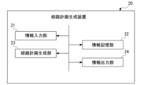
- FIG. 3 is a schematic block diagram showing a configuration example of the route plan generation device 20 according to the embodiment.
- the route plan generation device 20 can be configured using a computer such as a microcomputer or a CPU (Central Processing Unit), and hardware such as peripheral circuits and peripheral devices of the computer.
- the route plan generation device 20 has an information input section 21, an information storage section 22, a route plan generation section 23, and has a functional configuration composed of a combination of hardware and software such as a program executed by a computer.
- An information output section 24 is provided.
- the information input unit 21 receives from the outside terrain shape information indicating the shape of the terrain such as the surface of the ground G in the construction target area A, the position of the work vehicle 100, and design information indicating the target shape in the construction target area A. Accepts input of surface information and.
- the design information is obtained, for example, from an external CAD (Computer Aided Design) system that designs a construction site including the construction target area A.
- the terrain shape information is acquired by a detection device such as a radar included in the work vehicle 100.
- the detection device may be provided in another work vehicle or may be attached to a structure within the construction area A. Further, the detection device may be mounted on a flying vehicle that flies above the construction site.
- An example of the flying object is an unmanned aerial vehicle (UAV) such as a drone.
- UAV unmanned aerial vehicle
- the information storage unit 22 stores the topographic shape information and design surface information input by the information input unit 21. Further, the information storage unit 22 stores various vehicle information regarding the work vehicle 100, such as the size of the blade 133, the driving force of the crawlers 110a and 110b, and the maximum traveling speed.
- the route plan generation unit 23 generates a route plan for carrying out excavation work in the construction target area A with the work vehicle 100, as will be described in detail later.
- the information output unit 24 outputs the route plan information generated by the route plan generation unit 23 to the outside.
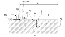
- FIG. 4 is a diagram illustrating an example of a moving route L of the working machine 130 in the traveling route R of the working vehicle 100 according to the embodiment.
- the route plan generation unit 23 generates a work equipment route plan and a travel route plan for the work vehicle 100 as a route plan for excavating the work vehicle 100 in the construction target area A.
- the movement route L of the work implement 130 indicates the vertical position and angle of the blade 133 at a plurality of positions on the travel route R when the work vehicle 100 travels along the travel route R.
- the route plan generation unit 23 generates a work implement route plan that is the optimal travel route L of the work machine 130 and a travel route plan that is the optimal travel route R of the work vehicle 100.
- the route plan generation unit 23 generates a work machine route plan and a travel route plan that prevent slippage of the tracks 110a and 110b of the work vehicle 100 and increase the excavation efficiency of the blade 133.
- the route plan generation unit 23 generates a work equipment route plan that is the optimal travel route L of the work machine 130 and a travel route R that is the optimal travel route R of the work vehicle 100 for the plurality of travel routes L and travel route R candidates. Reinforcement learning is performed to generate a route plan. In the present embodiment, simulations are performed multiple times for a plurality of moving routes L with various parameters related to the operation of the working machine 130 and candidates for the driving route R, while learning by reinforcement learning is performed.
- FIG. 5 is a diagram illustrating an example of a simulation model used by the route plan generation unit 23 according to the embodiment to simulate candidates for the travel route L and the travel route R.
- the route plan generation unit 23 decomposes the phenomena that occur during excavation by the work vehicle 100 into models for each element. For example, as shown in FIG. 5, the route plan generation unit 23 decomposes a phenomenon that occurs during excavation by the work vehicle 100 into a vehicle body model M10, a control model M20, and an earth and sand model M30, and performs reinforcement learning through simulation. Ru.
- the simulation is executed by a simulator running on a computer.
- the vehicle body model M10 relates to parameters related to the operation of the work vehicle 100 on the travel route R and parameters related to the operation of the work implement 130 on the travel route R. More specifically, the vehicle body model M10 includes, for example, a hydraulic model M11 related to hydraulic equipment such as a lift cylinder and a tilt cylinder of the working machine 130, a mechanism model M12 related to the mechanism of movable parts such as a lift frame 131 and a blade 133, and a lower traveling model M11. It includes an undercarriage model M13 related to the body 110.
- the hydraulic model M11 simulates, for example, relief pressure related to hydraulic equipment such as a lift cylinder and a tilt cylinder of the working machine 130.
- hydraulic equipment such as a lift cylinder and a tilt cylinder of the working machine 130.
- the maximum value of the reaction force due to the operation of the lift frame 131 and the blade 133 is set as the maximum reaction force limit.
- the relief pressure of the hydraulic equipment and the like associated with the operation of the working machine 130 is simulated within a range that does not exceed the maximum reaction force limit.
- the excavation range that can be excavated by the blade 133 is simulated when movable parts such as the lift frame 131 and the blade 133 are operated based on the movement path L.
- a position limit of the tip blade is set.
- the excavation operation by the blade 133 is simulated within a range that does not exceed the position limit of the tip blade.
- simulations are performed regarding the vehicle speed caused by the drive of the lower traveling body 110, the degree of slippage of the tracks 110a and 110b, and the like.
- the vehicle speed when the work vehicle 100 travels along the traveling route R by driving the lower traveling body 110 is received by the traveling driving force (traction force) by the tracks 110a and 110b and by pushing the earth and sand on the ground G by the blade 133. It is calculated based on the reaction force.
- the degree of slippage of the tracks 110a and 110b can be simulated based on the reaction force received from earth and sand when the lift frame 131 and the blade 133 perform an excavation operation, for example.
- This reaction force is the sum of the excavation resistance (shearing resistance) when the blade 133 excavates the ground G and the soil carrying resistance due to friction when pushing forward the earth and sand held in front of the blade 133.
- the reaction force reaches the maximum reaction force limit, it can be determined that the shoe slip limit of the tracks 110a and 110b is exceeded and slip occurs.
- the control model M20 relates to control conditions when performing a simulation based on candidates for the travel route L and the travel route R.
- the control model M20 includes, for example, a route following model M21 and a route planning model M22.
- the route following model M21 when performing a simulation, it is assumed that the trajectory followability of the work vehicle 100 for the travel route R and the trajectory followability for the movement route L of the work implement 130 are, for example, 100%. Assume.
- the route planning model M22 is set for a plurality of travel routes L and driving routes R, which are to be learned by performing simulations a plurality of times.
- the route planning model M22 generates new travel routes L and travel routes R based on the results of simulations performed on candidates for travel routes L and travel routes R so as to further improve excavation efficiency.
- a starting point P1 of the moving route L is temporarily set along the traveling route R, and an excavation start position P2 where the blade 133 is lowered to start excavating the ground G.
- the excavation depth P3 at which the ground G is excavated in one excavation, the penetration angle P4 of the blade 133 into the ground G, the end point P5 of the moving route L, the vehicle speed of the work vehicle 100, etc. are varied, and the simulation target is A plurality of moving route L candidates are sequentially generated.
- the route planning model M22 after performing a simulation on one candidate travel route L, another travel route L with different conditions is generated, and the simulations are sequentially executed.
- the earth and sand model M30 simulates parameters related to earth and sand on the ground G to be excavated by the work equipment 130 when the work vehicle 100 is driven and the work equipment 130 is moved based on each candidate of the travel route L and the travel route R. It is for the purpose of The earth and sand model M30 is classified into a terrain model M31 related to topographic changes caused by excavating the ground G with the blade 133, and a reaction force model M32 related to the reaction force that the blade 133 receives when excavating the ground G.
- the terrain model M31 by excavating the ground G with the blade 133, a simulation is performed on the amount of excavated soil to be excavated.
- the amount of excavated soil is calculated based on the difference between the topographic shape information of the ground G before excavation and the design surface information about the design surface S in the area along the travel route R.
- the amount of excavated soil in each excavation is based on the terrain shape before excavation and the one-time excavation along the movement route L. It can be calculated based on the difference from the excavated surface formed by excavation.
- FIG. 6 is a diagram showing another example of the moving route L of the working machine 130 in the traveling route R of the working vehicle 100 according to the embodiment.
- the amount of dirt D1 held is A simulation is performed for a certain amount of soil to be held.
- FIG. 7 is a diagram showing still another example of the moving route L of the working machine 130 in the traveling route R of the working vehicle 100 according to the embodiment.
- the excavated soil may be simulated based on the difference between the amount of excavated soil and the amount of backfilled soil that is the amount of backfilled earth and sand D2.
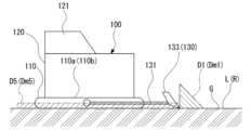
- FIG. 8 is a side view showing the dirt D1 held in front of the blade 133 and the windrow dirt D5 formed by overflowing to both sides of the blade 133 when excavating with the working machine 130 according to the embodiment. be.
- FIG. 9 is a plan view showing the dirt D1 held in front of the blade 133 and the windrow dirt D5 formed by overflowing to both sides of the blade 133 when excavating with the working machine 130 according to the embodiment. be.
- the terrain model M31 as shown in FIGS. 8 and 9, when the ground G is excavated with the blade 133 based on the travel route L and the travel route R, so-called windrows overflow to both sides in the width direction of the blade 133.
- a simulation is performed for the amount of earth and sand D5.
- the amount of earth and sand D1 to be held and the amount of earth and sand D5 in the windrow may be calculated based on, for example, a preliminary experiment using a model.
- the terrain model M31 for example, when backfilling a part of the earth and sand excavated on the travel route R at another position on the travel route R, the backfilled earth and sand is compacted by the crawler tracks 110a and 110b.
- a simulation is performed as follows: The terrain model M31 also simulates landslides caused by earth and sand excavated on the travel route R.
- the reaction force model M32 simulates the excavation resistance that the blade 133 receives from the earth and sand on the ground G when the blade 133 is operated along the movement path L.
- the excavation resistance increases depending on the depth of excavation into the ground G by the blade 1330.
- the reaction force model M32 also simulates the excavation resistance that the blade 133 receives from the backfill earth and sand D2.
- the simulator calculates that when the work vehicle 100 is moved along the travel route R and the work implement 130 is operated along the travel route L, the reaction force that the blade 133 receives from the earth and sand is: If the shoe slip limit of the undercarriage 110 is exceeded, a penalty value (for example, ⁇ 0.05) in reinforcement learning is given.
- a penalty value for example, ⁇ 0.05
- the simulator uses reinforcement learning to search for the optimal travel route L and travel route R based on the calculated reward and penalty value, and generates a route plan to generate a work equipment route plan and a travel route plan.
- Learn section 23 The route plan generation unit 23 generates a work equipment route plan for the entire construction target area A based on the work equipment route plan that is the optimal movement route L and the travel route plan that is the optimal travel route R. It is trained to generate route plans.
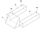
- FIG. 10 shows that when excavating with the working machine 130 according to the embodiment, the earth and sand D1 held in front of the blade 133 and the earth and sand D5 of the windrow formed by overflowing on both sides of the blade 133 are arranged in a polygonal shape. It is a diagram imitating three-dimensional models Dm1 and Dm5.
- the earth and sand D1 held in front of the blade 133 is converted into a polygonal prism-shaped (for example, triangular prism-shaped) three-dimensional model Dm1.
- a three-dimensional model of a polygonal prism shape (for example, a quadrangular prism shape (rectangular parallelepiped shape)) is Dm5 is simplified and calculated. This makes it possible to efficiently calculate the amount of windrow earth and sand D5, which changes from moment to moment as the ground G is excavated based on the moving route L. can.
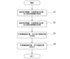
- FIG. 11 is a flowchart showing the operation of the route plan generation device 20 according to the embodiment.
- the route plan generation device 20 that has been trained by reinforcement learning is installed in, for example, the work vehicle 100.
- the route plan generation device 20 generates a route plan for performing excavation work on the ground G of the construction target area A with the work vehicle 100.
- the information input unit 21 first inputs topographical shape information indicating the shape of the ground G in the construction target area A, the position of the work vehicle 100, and the ground surface in the construction target area A.
- Design surface information indicating the shape in which G should be excavated is acquired from the outside (S1).
- the route plan generation unit 23 indicates a travel route R of the work vehicle 100, indicating a travel route L of the work machine 130, based on the terrain shape information, the position of the work vehicle 100, and the design surface information.
- a travel route plan is generated (S3).
- the information output unit 24 outputs the generated working machine route plan and traveling route plan to the outside (S4).
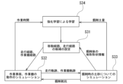
- FIG. 12 is a diagram schematically showing a flow in which the route plan generation unit 23 is learned by reinforcement learning according to the embodiment.
- Reinforcement learning can be performed using, for example, a simulator that runs on a computer outside the vehicle body 100 and executes a simulation. To do this, first, the simulator sets candidates for the travel route L of the work machine 130 and the candidate travel route R for the work vehicle 100 (S31).
- the simulator performs a simulation based on the set travel route L candidate and the travel route R candidate for the work vehicle 100.
- the operation of the work vehicle 100 and the work implement 130 is simulated using the vehicle body model M10 and the control model M20 (S32).
- the work vehicle 100 travels along the travel route R when operating the work implement 130. Simulate the trajectory.
- a movement locus of the working machine 130 when the working machine 130 is operated based on the moving route L is simulated.
- the simulator also calculates the working time when excavating based on the travel route L and the travel route R, based on the data of the travel trajectory of the work vehicle 100 and the travel trajectory of the work equipment 130 that have been calculated. .
- the simulator uses the earth and sand model M30 to perform a simulation of earth and sand when excavating earth and sand on the ground G based on the data of the travel trajectory of the work vehicle 100 and the movement trajectory of the work implement 130 ( S33).
- the earth and sand model M30 for example, excavation resistance when excavating earth and sand on the ground G is calculated.
- the calculated excavation resistance data is fed back to the vehicle body model M10 and reflected in the calculation of the vehicle speed of the work vehicle 100, etc.
- the simulator uses the earth and sand model M30 to calculate a post-excavation topography that indicates the shape of the ground G after excavation by the working machine 130. Further, the route plan generation unit 23 uses the earth and sand model M30 to calculate the amount of earth excavated by the working machine 130, the amount of earth held, the amount of earth in the windrow, etc.
- the simulator learns the route plan generation unit 23 by reinforcement learning based on the work time and the amount of excavated soil calculated as described above (S34). In reinforcement learning, rewards and penalties are calculated, and candidates for the travel route L and the travel route R are evaluated. At this time, the simulator shows that when the work vehicle 100 is moved along the travel route R and the work machine 130 excavates based on the travel route L, the excavation resistance exceeds the shoe slip limit of the tracks 110a and 110b. Determine whether or not the limit has been exceeded. As a result, if the excavation resistance exceeds the shoe slip limit, it is determined that the work vehicle 100 is slipping.
- the simulator performs a simulation on one travel route L and a candidate travel route R, then performs learning based on the evaluation results for the travel route L and candidate travel route R, and then performs a simulation.
- a candidate travel route L or travel route R is set.
- the candidate travel route L or travel route R to be simulated next is set so that the work vehicle 100 does not slip and the reward expressed by the above formula (1) is as large as possible.
- the route plan generation unit 23 is trained to generate a work machine route plan and a travel route plan that prevent the work vehicle 100 from slipping and have high excavation efficiency.
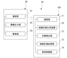
- FIG. 13 is a schematic block diagram showing a configuration example of a route plan generation system 50 for a work vehicle according to the embodiment. As shown in FIG. 13, the work vehicle route plan generation system 50 includes a remote control device 60 and a work vehicle 100.
- the remote control device 60 includes a communication section 61, an information output section 62, and a control section 63.
- the communication unit 61 can communicate with the work vehicle 100 using a public wireless communication network or wireless communication means.
- the information output unit 62 outputs information necessary for automatically driving the work vehicle 100.
- the information output unit 62 acquires, for example, design surface information of the construction target area A from an external CAD system, etc., and transmits it to the work vehicle 100 via the communication unit 61.
- the control unit 63 monitors the operating state of each part of the work vehicle 100 based on information detected by various sensors included in the work vehicle 100.
- the work vehicle 100 automatically operates based on the route plan generated by route plan generation device 20. For this reason, the work vehicle 100 includes a communication section 71, the route plan generation device 20, a position detection section 72, a route plan storage section 73, and a vehicle control section 74.
- the communication unit 71 can communicate with the communication unit 61 of the remote control device 60 via a public wireless communication network or wireless communication means.
- a part or all of the configuration of work vehicle 100 may be included in remote control device 60.
- the route plan generation device 20 shown above is provided on the work vehicle 100 side in this embodiment.
- the route plan generation device 20 may be provided on the remote control device 60 side.
- part or all of the configuration of the remote control device 60 may be provided in the work vehicle 100.
- the position detection unit 72 is provided in the work vehicle 100.
- the position detection unit 72 uses, for example, GPS, and is capable of detecting the position of the work vehicle 100.
- the route plan storage unit 73 stores the work equipment route plan and travel route plan of the work vehicle 100, which are generated by the route plan generation device 20 and output to the outside.
- the vehicle control unit 74 controls the operation of each part of the work machine 130 and the work vehicle 100 based on the work machine route plan and the travel route plan stored in the route plan storage unit 73.
- the work vehicle 100 performs work while moving the work vehicle 100 based on a work implement route plan that is the optimal travel route L for the work machine 130 and a travel route plan that is the optimal travel route R for the work vehicle 100.
- the machine 130 is operated. Thereby, the ground G can be excavated efficiently.
- the work vehicle 100 is a bulldozer, but is not limited to this.
- the work vehicle 100 may be a work machine including a work machine such as a hydraulic excavator, a wheel loader, a motor grader, and a running body.
- part or all of the program executed by the computer in the above embodiments can be distributed via a computer-readable recording medium or a communication line.
- a route plan for a work vehicle can be efficiently generated.
Landscapes
- Engineering & Computer Science (AREA)
- Mining & Mineral Resources (AREA)
- Civil Engineering (AREA)
- General Engineering & Computer Science (AREA)
- Structural Engineering (AREA)
- Operation Control Of Excavators (AREA)
- Control Of Position, Course, Altitude, Or Attitude Of Moving Bodies (AREA)
Abstract
Description
本願は、2022年6月30日に、日本に出願された特願2022-106372号に基づき優先権を主張し、その内容をここに援用する。
図1は、実施形態に係る作業車両100(作業機械)で掘削作業を行う施工対象エリアAを示す平面図である。図2は、実施形態に係る作業車両100で掘削作業を行う施工対象エリアAの側断面図である。
図1、図2に示すように、本実施形態において、作業車両100は、予め定められた施工対象エリアAの地面Gに対して掘削作業を行う。作業車両100は、地面Gを掘削することによって、予め設計された設計面Sに沿った掘削地表面Kを形成する。なお、図1、図2に示した施工対象エリアAは一例に過ぎず、その平面形状等は適宜変更可能である。また、地面Gの地表面の地形形状、設計面S(掘削地表面K)の形状も一例に過ぎず、適宜変更可能である。
図3は、実施形態に係る経路計画生成装置20の構成例を示す概略ブロック図である。
図3に示すように、経路計画生成装置20は、マイクロコンピュータ、CPU(Central Processing Unit)等のコンピュータと、コンピュータの周辺回路や周辺装置等のハードウェアを用いて構成することができる。経路計画生成装置20は、ハードウェアと、コンピュータが実行するプログラム等のソフトウェアとの組み合わせから構成される機能的構成として、情報入力部21と、情報記憶部22と、経路計画生成部23と、情報出力部24と、を備える。
情報出力部24は、経路計画生成部23によって生成された経路計画の情報を、外部に出力する。
図4は、実施形態に係る作業車両100の走行経路Rにおける、作業機130の移動経路Lの一例を示す図である。
経路計画生成部23は、施工対象エリアA内を作業車両100で掘削施工するための経路計画として、作業車両100の作業機経路計画、及び走行経路計画を生成する。作業機130の移動経路Lは、作業車両100が走行経路Rに沿って走行する際に、走行経路R上の複数の位置における、ブレード133の上下方向の位置、角度を示すものである。
経路計画生成部23は、移動経路L、及び走行経路Rの候補についてのシミュレーションを行うため、作業車両100による掘削時に生じる現象を、要素毎のモデルに分解する。例えば、図5に示すように、経路計画生成部23は、作業車両100による掘削時に生じる現象を、車体モデルM10と、制御モデルM20と、土砂モデルM30と、に分解してシミュレーションにより強化学習される。コンピュータ上で動作する、シミュレーションを実行するシミュレータにより、シミュレーションは実行される。
経路追従モデルM21では、シミュレーションを行う際に、作業車両100の走行経路Rに対する軌跡追従性、作業機130の移動経路Lに対する軌跡追従性について、例えば、それぞれ、100%の追従性を有する、と仮定する。
また、図6に示すように、移動経路Lに基づいてブレード133で地面Gを掘削し、ブレード133の前方に土砂D1を抱え込んでいる場合、地形モデルM31では、抱え込んでいる土砂D1の量である抱え込み土量について、シミュレーションを行う。
図7に示すように、ブレード133で走行経路R上の地面Gの一部を掘削した土砂D2により、走行経路R上の地面Gの他の部分を埋め戻す場合、地形モデルM31では、掘削土量と、埋め戻した土砂D2の量である埋め戻し土量と、の差に基づき、実質的な掘削土量について、シミュレーションを行うようにしてもよい。
地形モデルM31では、図8、図9に示すように、移動経路L、及び走行経路Rに基づいてブレード133で地面Gを掘削した際に、ブレード133の幅方向両側にあふれ出す、いわゆるウィンドローの土砂D5の量について、シミュレーションを行う。地形モデルM31では、一つの走行経路Rに沿って、移動経路Lに基づいてブレード133で地面Gを掘削することによって、地面G上にウィンドローが形成された場合、形成されたウィンドローの土砂D5の量を、他の走行経路Rにおいて、移動経路Lの候補についてシミュレーションを行う際に、地形情報に含めるものとする。
これ以外に、地形モデルM31では、例えば、走行経路R上で掘削した土砂の一部を、走行経路R上の他の位置で埋め戻す場合、埋め戻した土砂を、履帯110a、110bで転圧して締め固める、として、シミュレーションを行う。
地形モデルM31では、走行経路R上で掘削した土砂についての土崩れについてもシミュレーションを行う。
報酬=掘削土量/作業時間 ・・・(1)
経路計画生成部23は、最適な移動経路Lである作業機経路計画、及び最適な走行経路Rである走行経路計画に基づき、施工対象エリアAの全体を対象とした作業機経路計画、及び走行経路計画を生成するように学習される。
ところで、図8~図10に示すように、上記のような経路計画生成部23の地形モデルM31では、ブレード133の前方に抱え込んでいる土砂D1を、多角柱状(例えば三角柱状)の立体モデルDm1に模して単純化し、抱え込み土量を算出する。これにより、移動経路Lに基づいて地面Gを掘削するにともなって時々刻々と変化する抱え込み土量を、効率的に算出することができる。
図11は、実施形態に係る経路計画生成装置20の動作を示すフローチャートである。
強化学習により学習された経路計画生成装置20は、例えば作業車両100に備えられる。経路計画生成装置20は、施工対象エリアAの地面Gに対して作業車両100で掘削作業を行うための経路計画を生成する。
これには、図11に示すように、まず、情報入力部21が、施工対象エリアA内の地面Gの形状を示す地形形状情報、作業車両100の位置、及び、施工対象エリアA内の地面Gを掘削すべき形状を示す設計面情報を、外部から取得する(S1)。次に、取得した地形形状情報、作業車両100の位置、及び設計面情報を、情報記憶部22に記憶する(S2)。次に、経路計画生成部23で、地形形状情報、作業車両100の位置、及び設計面情報に基づいて、作業機130の移動経路Lを示す作業機経路計画作業車両100の走行経路Rを示す走行経路計画を生成する(S3)。その後、情報出力部24が、生成された作業機経路計画、及び走行経路計画を、外部に出力する(S4)。
これには、まず、シミュレータが、作業機130の移動経路Lの候補と作業車両100の走行経路Rの候補を設定する(S31)。
また、シミュレータは、算出された作業車両100の走行軌跡、及び作業機130の移動軌跡のデータに基づいて、移動経路L、及び走行経路Rに基づいて掘削を行った際の作業時間を算出する。
図13は、実施形態に係る作業車両の経路計画生成システム50の構成例を示す概略ブロック図である。
図13に示すように、作業車両の経路計画生成システム50は、遠隔制御装置60と、作業車両100と、を備えている。
通信部61は、公衆無線通信網、無線通信手段により、作業車両100と通信可能である。
管制部63は、作業車両100に備えられた各種のセンサにより検出された情報に基づき、作業車両100の各部の動作状態を監視する。
このため、作業車両100は、通信部71と、上記経路計画生成装置20と、位置検出部72と、経路計画記憶部73と、車両制御部74と、を備えている。
なお、作業車両100の一部または全部の構成は、遠隔制御装置60に備えられても良い。例えば、上記で示した経路計画生成装置20は、本実施形態において、作業車両100側に備えられている。経路計画生成装置20は、遠隔制御装置60側に備えられていてもよい。また、遠隔制御装置60の一部または全部の構成は、作業車両100に備えられても良い。
車両制御部74は、経路計画記憶部73に記憶された作業機経路計画、及び走行経路計画に基づいて、作業機130、及び作業車両100の各部動作を制御する。作業車両100は、作業機130の最適な移動経路Lである作業機経路計画と、作業車両100の最適な走行経路Rである走行経路計画とに基づいて、作業車両100を移動させながら、作業機130を動作させる。これにより、地面Gの掘削が効率良く行われる。
本実施形態によれば、作業車両10の経路計画を、効率良く生成することができる。
Claims (9)
- 作業機を有した作業車両で、施工対象エリアの地面に対して掘削作業を行うための経路計画を生成する作業車両の経路計画生成システムであって、
前記作業車両の位置を検出する位置検出部と、
前記施工対象エリア内の地形の形状を示す地形形状情報、前記作業車両の位置、及び前記施工対象エリア内の目標形状を示す設計面情報を記憶する情報記憶部と、
前記地形形状情報、前記作業車両の位置、及び前記設計面情報に基づいて、前記作業機の移動経路を示す作業機経路計画、及び前記作業車両の走行経路を示す走行経路計画を生成する経路計画生成部と、
を備える作業車両の経路計画生成システム。 - 前記経路計画生成部は、最適な前記走行経路、及び最適な前記移動経路を生成するように強化学習される、
請求項1に記載の作業車両の経路計画生成システム。 - 前記経路計画生成部は、少なくとも、前記作業機により掘削される土砂、及び、前記走行経路上における前記作業車両に関するパラメータを用いたシミュレーションを複数回行うことで、前記強化学習される、
請求項2に記載の作業車両の経路計画生成システム。 - 前記経路計画生成部は、前記走行経路に沿って前記作業車両を移動させたときの、掘削土量、及び作業時間の少なくとも一方を用いた報酬に基づいて、前記強化学習される、
請求項2又は3に記載の作業車両の経路計画生成システム。 - 前記経路計画生成部は、前記走行経路に沿って前記作業車両を移動させ、前記作業機で前記地面を掘削する前と後における地形の差に基づく、前記作業機での抱え込み土量に基づいて、算出された前記掘削土量を用いて前記強化学習される、
請求項4に記載の作業車両の経路計画生成システム。 - 前記経路計画生成部は、前記走行経路に沿って前記作業車両を移動させた後、前記作業機の前方に抱え込まれた土砂を、多角柱状の立体モデルに模すことで、算出された前記抱え込み土量を用いて前記強化学習される、
請求項5に記載の作業車両の経路計画生成システム。 - 前記経路計画生成部は、前記走行経路に沿って前記作業車両を移動させた場合に、前記作業機の両側にはみ出すうね状のウィンドローの土量に基づいて、算出された前記掘削土量を用いて前記強化学習される、
請求項5に記載の作業車両の経路計画生成システム。 - 前記経路計画生成部は、前記ウィンドローを、多角柱状の立体モデルに模すことで、算出された前記ウィンドローの土量を用いて前記強化学習される、
請求項7に記載の作業車両の経路計画生成システム。 - 作業機を有した作業車両で、施工対象エリアの地面に対して掘削作業を行うための経路計画を生成する作業車両の経路計画生成方法であって、
前記作業車両の位置を検出するステップと、
前記施工対象エリア内の地形の形状を示す地形形状情報、前記作業車両の位置、及び前記施工対象エリア内の前記地面を掘削すべき形状を示す設計面情報を記憶するステップと、
前記地形形状情報、前記作業車両の位置、及び前記設計面情報に基づいて、前記作業機の移動経路を示す作業機経路計画、及び前記作業車両の走行経路を示す走行経路計画を生成するステップと、
を含む、作業車両の経路計画生成方法。
Priority Applications (3)
| Application Number | Priority Date | Filing Date | Title |
|---|---|---|---|
| CA3248992A CA3248992A1 (en) | 2022-06-30 | 2023-06-30 | SYSTEM AND METHOD FOR GENERATION OF CONSTRUCTION EQUIPMENT TRAIL PLANS |
| AU2023297524A AU2023297524A1 (en) | 2022-06-30 | 2023-06-30 | Work vehicle path plan generation system and work vehicle path plan generation method |
| US18/857,211 US20250277351A1 (en) | 2022-06-30 | 2023-06-30 | Work vehicle path plan generation system and work vehicle path plan generation method |
Applications Claiming Priority (2)
| Application Number | Priority Date | Filing Date | Title |
|---|---|---|---|
| JP2022106372A JP2024005910A (ja) | 2022-06-30 | 2022-06-30 | 作業車両の経路計画生成システム、作業車両の経路計画生成方法 |
| JP2022-106372 | 2022-06-30 |
Publications (1)
| Publication Number | Publication Date |
|---|---|
| WO2024005182A1 true WO2024005182A1 (ja) | 2024-01-04 |
Family
ID=89380784
Family Applications (1)
| Application Number | Title | Priority Date | Filing Date |
|---|---|---|---|
| PCT/JP2023/024347 Ceased WO2024005182A1 (ja) | 2022-06-30 | 2023-06-30 | 作業車両の経路計画生成システム、作業車両の経路計画生成方法 |
Country Status (5)
| Country | Link |
|---|---|
| US (1) | US20250277351A1 (ja) |
| JP (1) | JP2024005910A (ja) |
| AU (1) | AU2023297524A1 (ja) |
| CA (1) | CA3248992A1 (ja) |
| WO (1) | WO2024005182A1 (ja) |
Families Citing this family (4)
| Publication number | Priority date | Publication date | Assignee | Title |
|---|---|---|---|---|
| JP2025118266A (ja) * | 2024-01-31 | 2025-08-13 | 株式会社小松製作所 | 作業機械の制御システム、作業機械、及び作業機械の制御方法 |
| WO2025181914A1 (ja) * | 2024-02-27 | 2025-09-04 | 日本電気株式会社 | 制御計画作成装置および制御計画作成方法 |
| WO2025181913A1 (ja) * | 2024-02-27 | 2025-09-04 | 日本電気株式会社 | 制御計画作成装置および制御計画作成方法 |
| JP2025132416A (ja) * | 2024-02-29 | 2025-09-10 | 株式会社小松製作所 | 作業車両の制御システムおよび作業車両の制御方法 |
Citations (6)
| Publication number | Priority date | Publication date | Assignee | Title |
|---|---|---|---|---|
| US20120136508A1 (en) * | 2010-11-30 | 2012-05-31 | Taylor Michael A | System for automated excavation planning and control |
| US20190055715A1 (en) * | 2017-08-15 | 2019-02-21 | Caterpillar Inc. | System and method for controlling earthmoving machines |
| WO2019189888A1 (ja) * | 2018-03-30 | 2019-10-03 | 住友重機械工業株式会社 | 建設機械の運転支援システム、建設機械 |
| US20200105072A1 (en) * | 2016-12-23 | 2020-04-02 | Caterpillar Sarl | Monitoring The Operation Of A Work Machine |
| WO2020226848A1 (en) * | 2019-05-03 | 2020-11-12 | Caterpillar Inc. | System for controlling the position of a work implement |
| JP2021113487A (ja) * | 2020-01-17 | 2021-08-05 | バイドゥ ユーエスエイ エルエルシーBaidu USA LLC | 自律走行車両ためのニューラル・タスク計画部 |
Family Cites Families (7)
| Publication number | Priority date | Publication date | Assignee | Title |
|---|---|---|---|---|
| US9378663B2 (en) * | 2011-06-27 | 2016-06-28 | Caterpillar Inc. | Method and system for mapping terrain using machine parameters |
| WO2018087830A1 (ja) * | 2016-11-09 | 2018-05-17 | 株式会社小松製作所 | 作業車両およびデータ較正方法 |
| US11641790B2 (en) * | 2018-05-09 | 2023-05-09 | Deere & Company | Method of planning a path for a vehicle having a work tool and a vehicle path planning system |
| JP7358164B2 (ja) * | 2019-09-30 | 2023-10-10 | 株式会社小松製作所 | 制御システム、作業車両の制御方法、および、作業車両 |
| JP7358163B2 (ja) * | 2019-09-30 | 2023-10-10 | 株式会社小松製作所 | 制御システム、作業車両の制御方法、および、作業車両 |
| US12029156B1 (en) * | 2020-01-09 | 2024-07-09 | Euchron, Inc. | System and method for autonomous lawn care |
| US12024862B2 (en) * | 2020-02-07 | 2024-07-02 | Caterpillar Inc. | System and method of autonomously clearing a windrow |
-
2022
- 2022-06-30 JP JP2022106372A patent/JP2024005910A/ja active Pending
-
2023
- 2023-06-30 CA CA3248992A patent/CA3248992A1/en active Pending
- 2023-06-30 AU AU2023297524A patent/AU2023297524A1/en active Pending
- 2023-06-30 US US18/857,211 patent/US20250277351A1/en active Pending
- 2023-06-30 WO PCT/JP2023/024347 patent/WO2024005182A1/ja not_active Ceased
Patent Citations (6)
| Publication number | Priority date | Publication date | Assignee | Title |
|---|---|---|---|---|
| US20120136508A1 (en) * | 2010-11-30 | 2012-05-31 | Taylor Michael A | System for automated excavation planning and control |
| US20200105072A1 (en) * | 2016-12-23 | 2020-04-02 | Caterpillar Sarl | Monitoring The Operation Of A Work Machine |
| US20190055715A1 (en) * | 2017-08-15 | 2019-02-21 | Caterpillar Inc. | System and method for controlling earthmoving machines |
| WO2019189888A1 (ja) * | 2018-03-30 | 2019-10-03 | 住友重機械工業株式会社 | 建設機械の運転支援システム、建設機械 |
| WO2020226848A1 (en) * | 2019-05-03 | 2020-11-12 | Caterpillar Inc. | System for controlling the position of a work implement |
| JP2021113487A (ja) * | 2020-01-17 | 2021-08-05 | バイドゥ ユーエスエイ エルエルシーBaidu USA LLC | 自律走行車両ためのニューラル・タスク計画部 |
Also Published As
| Publication number | Publication date |
|---|---|
| AU2023297524A1 (en) | 2024-11-07 |
| JP2024005910A (ja) | 2024-01-17 |
| CA3248992A1 (en) | 2025-03-17 |
| US20250277351A1 (en) | 2025-09-04 |
Similar Documents
| Publication | Publication Date | Title |
|---|---|---|
| WO2024005182A1 (ja) | 作業車両の経路計画生成システム、作業車両の経路計画生成方法 | |
| AU2013260731B2 (en) | System and method for optimizing a cut location | |
| AU2013263703B2 (en) | System and method for optimizing a cut location | |
| AU2013263705B2 (en) | System and method for modifying a path for a machine | |
| CN112900519B (zh) | 工程机械的控制方法及系统 | |
| US9760081B2 (en) | System and method for optimizing a work implement path | |
| US9487929B2 (en) | Systems and methods for adjusting pass depth in view of excess materials | |
| US10883248B2 (en) | Road maintenance using stored maintenance passes | |
| US20230243130A1 (en) | Excavation plan creation device, working machine, and excavation plan creation method | |
| US9014924B2 (en) | System and method for estimating material characteristics | |
| US20250163671A1 (en) | Autonomous Control Of Powered Earth-Moving Vehicles To Control Ripper Tool Operations | |
| CN108222094B (zh) | 双铲板器具系统 | |
| US20250163681A1 (en) | Autonomous Control Of Powered Earth-Moving Vehicles To Control Slope-Based Stopping Operations | |
| US20250171983A1 (en) | Autonomous Control Of Powered Earth-Moving Vehicles To Control Calibration Operations For On-Vehicle Sensors | |
| US12460376B2 (en) | Elevation increment-decrement with slope control | |
| Ozaki et al. | Blade control for bulk dozer push by bulldozer using reinforcement learning | |
| JP2025132416A (ja) | 作業車両の制御システムおよび作業車両の制御方法 | |
| US20250163673A1 (en) | Autonomous Control Of Powered Earth-Moving Vehicles To Control Steering Operations Using A Blade Tool | |
| US12618223B1 (en) | Autonomous control of powered earth-moving vehicles to rectify vehicle slippage | |
| US12523012B1 (en) | Configurable system for layered system control of earth-moving construction and/or mining vehicles | |
| Samid | Infrastructure robotics: A trade-off study examining both autonomously and manually controlled approaches to lunar excavation and construction | |
| US20250163672A1 (en) | Autonomous Control Of Powered Earth-Moving Vehicles To Control Blade Tool Loading Operations | |
| CA3164854A1 (en) | Methods and systems for guiding mission planning in a machine system |
Legal Events
| Date | Code | Title | Description |
|---|---|---|---|
| 121 | Ep: the epo has been informed by wipo that ep was designated in this application |
Ref document number: 23831621 Country of ref document: EP Kind code of ref document: A1 |
|
| WWE | Wipo information: entry into national phase |
Ref document number: 18857211 Country of ref document: US |
|
| WWE | Wipo information: entry into national phase |
Ref document number: AU2023297524 Country of ref document: AU |
|
| ENP | Entry into the national phase |
Ref document number: 2023297524 Country of ref document: AU Date of ref document: 20230630 Kind code of ref document: A |
|
| NENP | Non-entry into the national phase |
Ref country code: DE |
|
| 122 | Ep: pct application non-entry in european phase |
Ref document number: 23831621 Country of ref document: EP Kind code of ref document: A1 |
|
| WWP | Wipo information: published in national office |
Ref document number: 18857211 Country of ref document: US |