WO2023286335A1 - システム、プログラム及び情報処理方法 - Google Patents
システム、プログラム及び情報処理方法 Download PDFInfo
- Publication number
- WO2023286335A1 WO2023286335A1 PCT/JP2022/009692 JP2022009692W WO2023286335A1 WO 2023286335 A1 WO2023286335 A1 WO 2023286335A1 JP 2022009692 W JP2022009692 W JP 2022009692W WO 2023286335 A1 WO2023286335 A1 WO 2023286335A1
- Authority
- WO
- WIPO (PCT)
- Prior art keywords
- tissue
- image
- energy
- information
- estimated
- Prior art date
- Legal status (The legal status is an assumption and is not a legal conclusion. Google has not performed a legal analysis and makes no representation as to the accuracy of the status listed.)
- Ceased
Links
Images


Classifications
-
- G—PHYSICS
- G06—COMPUTING OR CALCULATING; COUNTING
- G06V—IMAGE OR VIDEO RECOGNITION OR UNDERSTANDING
- G06V40/00—Recognition of biometric, human-related or animal-related patterns in image or video data
- G06V40/60—Static or dynamic means for assisting the user to position a body part for biometric acquisition
- G06V40/67—Static or dynamic means for assisting the user to position a body part for biometric acquisition by interactive indications to the user
-
- A—HUMAN NECESSITIES
- A61—MEDICAL OR VETERINARY SCIENCE; HYGIENE
- A61B—DIAGNOSIS; SURGERY; IDENTIFICATION
- A61B5/00—Measuring for diagnostic purposes; Identification of persons
- A61B5/0093—Detecting, measuring or recording by applying one single type of energy and measuring its conversion into another type of energy
-
- A—HUMAN NECESSITIES
- A61—MEDICAL OR VETERINARY SCIENCE; HYGIENE
- A61B—DIAGNOSIS; SURGERY; IDENTIFICATION
- A61B17/00—Surgical instruments, devices or methods
-
- A—HUMAN NECESSITIES
- A61—MEDICAL OR VETERINARY SCIENCE; HYGIENE
- A61B—DIAGNOSIS; SURGERY; IDENTIFICATION
- A61B18/00—Surgical instruments, devices or methods for transferring non-mechanical forms of energy to or from the body
- A61B18/04—Surgical instruments, devices or methods for transferring non-mechanical forms of energy to or from the body by heating
- A61B18/12—Surgical instruments, devices or methods for transferring non-mechanical forms of energy to or from the body by heating by passing a current through the tissue to be heated, e.g. high-frequency current
- A61B18/14—Probes or electrodes therefor
- A61B18/1442—Probes having pivoting end effectors, e.g. forceps
- A61B18/1445—Probes having pivoting end effectors, e.g. forceps at the distal end of a shaft, e.g. forceps or scissors at the end of a rigid rod
-
- A—HUMAN NECESSITIES
- A61—MEDICAL OR VETERINARY SCIENCE; HYGIENE
- A61B—DIAGNOSIS; SURGERY; IDENTIFICATION
- A61B34/00—Computer-aided surgery; Manipulators or robots specially adapted for use in surgery
- A61B34/20—Surgical navigation systems; Devices for tracking or guiding surgical instruments, e.g. for frameless stereotaxis
-
- A—HUMAN NECESSITIES
- A61—MEDICAL OR VETERINARY SCIENCE; HYGIENE
- A61N—ELECTROTHERAPY; MAGNETOTHERAPY; RADIATION THERAPY; ULTRASOUND THERAPY
- A61N7/00—Ultrasound therapy
- A61N7/02—Localised ultrasound hyperthermia
-
- G—PHYSICS
- G06—COMPUTING OR CALCULATING; COUNTING
- G06T—IMAGE DATA PROCESSING OR GENERATION, IN GENERAL
- G06T7/00—Image analysis
- G06T7/0002—Inspection of images, e.g. flaw detection
- G06T7/0012—Biomedical image inspection
-
- G—PHYSICS
- G06—COMPUTING OR CALCULATING; COUNTING
- G06T—IMAGE DATA PROCESSING OR GENERATION, IN GENERAL
- G06T7/00—Image analysis
- G06T7/10—Segmentation; Edge detection
- G06T7/11—Region-based segmentation
-
- G—PHYSICS
- G06—COMPUTING OR CALCULATING; COUNTING
- G06T—IMAGE DATA PROCESSING OR GENERATION, IN GENERAL
- G06T7/00—Image analysis
- G06T7/70—Determining position or orientation of objects or cameras
- G06T7/73—Determining position or orientation of objects or cameras using feature-based methods
-
- G—PHYSICS
- G06—COMPUTING OR CALCULATING; COUNTING
- G06V—IMAGE OR VIDEO RECOGNITION OR UNDERSTANDING
- G06V10/00—Arrangements for image or video recognition or understanding
- G06V10/20—Image preprocessing
- G06V10/25—Determination of region of interest [ROI] or a volume of interest [VOI]
-
- G—PHYSICS
- G16—INFORMATION AND COMMUNICATION TECHNOLOGY [ICT] SPECIALLY ADAPTED FOR SPECIFIC APPLICATION FIELDS
- G16H—HEALTHCARE INFORMATICS, i.e. INFORMATION AND COMMUNICATION TECHNOLOGY [ICT] SPECIALLY ADAPTED FOR THE HANDLING OR PROCESSING OF MEDICAL OR HEALTHCARE DATA
- G16H20/00—ICT specially adapted for therapies or health-improving plans, e.g. for handling prescriptions, for steering therapy or for monitoring patient compliance
- G16H20/40—ICT specially adapted for therapies or health-improving plans, e.g. for handling prescriptions, for steering therapy or for monitoring patient compliance relating to mechanical, radiation or invasive therapies, e.g. surgery, laser therapy, dialysis or acupuncture
-
- G—PHYSICS
- G16—INFORMATION AND COMMUNICATION TECHNOLOGY [ICT] SPECIALLY ADAPTED FOR SPECIFIC APPLICATION FIELDS
- G16H—HEALTHCARE INFORMATICS, i.e. INFORMATION AND COMMUNICATION TECHNOLOGY [ICT] SPECIALLY ADAPTED FOR THE HANDLING OR PROCESSING OF MEDICAL OR HEALTHCARE DATA
- G16H30/00—ICT specially adapted for the handling or processing of medical images
- G16H30/40—ICT specially adapted for the handling or processing of medical images for processing medical images, e.g. editing
-
- G—PHYSICS
- G16—INFORMATION AND COMMUNICATION TECHNOLOGY [ICT] SPECIALLY ADAPTED FOR SPECIFIC APPLICATION FIELDS
- G16H—HEALTHCARE INFORMATICS, i.e. INFORMATION AND COMMUNICATION TECHNOLOGY [ICT] SPECIALLY ADAPTED FOR THE HANDLING OR PROCESSING OF MEDICAL OR HEALTHCARE DATA
- G16H40/00—ICT specially adapted for the management or administration of healthcare resources or facilities; ICT specially adapted for the management or operation of medical equipment or devices
- G16H40/40—ICT specially adapted for the management or administration of healthcare resources or facilities; ICT specially adapted for the management or operation of medical equipment or devices for the management of medical equipment or devices, e.g. scheduling maintenance or upgrades
-
- G—PHYSICS
- G16—INFORMATION AND COMMUNICATION TECHNOLOGY [ICT] SPECIALLY ADAPTED FOR SPECIFIC APPLICATION FIELDS
- G16H—HEALTHCARE INFORMATICS, i.e. INFORMATION AND COMMUNICATION TECHNOLOGY [ICT] SPECIALLY ADAPTED FOR THE HANDLING OR PROCESSING OF MEDICAL OR HEALTHCARE DATA
- G16H40/00—ICT specially adapted for the management or administration of healthcare resources or facilities; ICT specially adapted for the management or operation of medical equipment or devices
- G16H40/60—ICT specially adapted for the management or administration of healthcare resources or facilities; ICT specially adapted for the management or operation of medical equipment or devices for the operation of medical equipment or devices
- G16H40/63—ICT specially adapted for the management or administration of healthcare resources or facilities; ICT specially adapted for the management or operation of medical equipment or devices for the operation of medical equipment or devices for local operation
-
- G—PHYSICS
- G16—INFORMATION AND COMMUNICATION TECHNOLOGY [ICT] SPECIALLY ADAPTED FOR SPECIFIC APPLICATION FIELDS
- G16H—HEALTHCARE INFORMATICS, i.e. INFORMATION AND COMMUNICATION TECHNOLOGY [ICT] SPECIALLY ADAPTED FOR THE HANDLING OR PROCESSING OF MEDICAL OR HEALTHCARE DATA
- G16H50/00—ICT specially adapted for medical diagnosis, medical simulation or medical data mining; ICT specially adapted for detecting, monitoring or modelling epidemics or pandemics
- G16H50/20—ICT specially adapted for medical diagnosis, medical simulation or medical data mining; ICT specially adapted for detecting, monitoring or modelling epidemics or pandemics for computer-aided diagnosis, e.g. based on medical expert systems
-
- A—HUMAN NECESSITIES
- A61—MEDICAL OR VETERINARY SCIENCE; HYGIENE
- A61B—DIAGNOSIS; SURGERY; IDENTIFICATION
- A61B17/00—Surgical instruments, devices or methods
- A61B2017/0042—Surgical instruments, devices or methods with special provisions for gripping
-
- A—HUMAN NECESSITIES
- A61—MEDICAL OR VETERINARY SCIENCE; HYGIENE
- A61B—DIAGNOSIS; SURGERY; IDENTIFICATION
- A61B18/00—Surgical instruments, devices or methods for transferring non-mechanical forms of energy to or from the body
- A61B2018/00571—Surgical instruments, devices or methods for transferring non-mechanical forms of energy to or from the body for achieving a particular surgical effect
- A61B2018/00577—Ablation
-
- A—HUMAN NECESSITIES
- A61—MEDICAL OR VETERINARY SCIENCE; HYGIENE
- A61B—DIAGNOSIS; SURGERY; IDENTIFICATION
- A61B18/00—Surgical instruments, devices or methods for transferring non-mechanical forms of energy to or from the body
- A61B2018/00636—Sensing and controlling the application of energy
- A61B2018/00696—Controlled or regulated parameters
- A61B2018/00702—Power or energy
-
- A—HUMAN NECESSITIES
- A61—MEDICAL OR VETERINARY SCIENCE; HYGIENE
- A61B—DIAGNOSIS; SURGERY; IDENTIFICATION
- A61B18/00—Surgical instruments, devices or methods for transferring non-mechanical forms of energy to or from the body
- A61B2018/00636—Sensing and controlling the application of energy
- A61B2018/00773—Sensed parameters
- A61B2018/00791—Temperature
-
- A—HUMAN NECESSITIES
- A61—MEDICAL OR VETERINARY SCIENCE; HYGIENE
- A61B—DIAGNOSIS; SURGERY; IDENTIFICATION
- A61B18/00—Surgical instruments, devices or methods for transferring non-mechanical forms of energy to or from the body
- A61B2018/00636—Sensing and controlling the application of energy
- A61B2018/00898—Alarms or notifications created in response to an abnormal condition
-
- A—HUMAN NECESSITIES
- A61—MEDICAL OR VETERINARY SCIENCE; HYGIENE
- A61B—DIAGNOSIS; SURGERY; IDENTIFICATION
- A61B5/00—Measuring for diagnostic purposes; Identification of persons
- A61B5/05—Detecting, measuring or recording for diagnosis by means of electric currents or magnetic fields; Measuring using microwaves or radio waves
- A61B5/053—Measuring electrical impedance or conductance of a portion of the body
- A61B5/0538—Measuring electrical impedance or conductance of a portion of the body invasively, e.g. using a catheter
-
- A—HUMAN NECESSITIES
- A61—MEDICAL OR VETERINARY SCIENCE; HYGIENE
- A61B—DIAGNOSIS; SURGERY; IDENTIFICATION
- A61B5/00—Measuring for diagnostic purposes; Identification of persons
- A61B5/48—Other medical applications
- A61B5/4848—Monitoring or testing the effects of treatment, e.g. of medication
-
- A—HUMAN NECESSITIES
- A61—MEDICAL OR VETERINARY SCIENCE; HYGIENE
- A61B—DIAGNOSIS; SURGERY; IDENTIFICATION
- A61B5/00—Measuring for diagnostic purposes; Identification of persons
- A61B5/68—Arrangements of detecting, measuring or recording means, e.g. sensors, in relation to patient
- A61B5/6846—Arrangements of detecting, measuring or recording means, e.g. sensors, in relation to patient specially adapted to be brought in contact with an internal body part, i.e. invasive
- A61B5/6847—Arrangements of detecting, measuring or recording means, e.g. sensors, in relation to patient specially adapted to be brought in contact with an internal body part, i.e. invasive mounted on an invasive device
-
- G—PHYSICS
- G06—COMPUTING OR CALCULATING; COUNTING
- G06T—IMAGE DATA PROCESSING OR GENERATION, IN GENERAL
- G06T2207/00—Indexing scheme for image analysis or image enhancement
- G06T2207/10—Image acquisition modality
- G06T2207/10068—Endoscopic image
-
- G—PHYSICS
- G06—COMPUTING OR CALCULATING; COUNTING
- G06T—IMAGE DATA PROCESSING OR GENERATION, IN GENERAL
- G06T2207/00—Indexing scheme for image analysis or image enhancement
- G06T2207/20—Special algorithmic details
- G06T2207/20081—Training; Learning
-
- G—PHYSICS
- G06—COMPUTING OR CALCULATING; COUNTING
- G06T—IMAGE DATA PROCESSING OR GENERATION, IN GENERAL
- G06T2207/00—Indexing scheme for image analysis or image enhancement
- G06T2207/20—Special algorithmic details
- G06T2207/20084—Artificial neural networks [ANN]
-
- G—PHYSICS
- G06—COMPUTING OR CALCULATING; COUNTING
- G06T—IMAGE DATA PROCESSING OR GENERATION, IN GENERAL
- G06T2207/00—Indexing scheme for image analysis or image enhancement
- G06T2207/30—Subject of image; Context of image processing
- G06T2207/30004—Biomedical image processing
- G06T2207/30024—Cell structures in vitro; Tissue sections in vitro
-
- G—PHYSICS
- G06—COMPUTING OR CALCULATING; COUNTING
- G06V—IMAGE OR VIDEO RECOGNITION OR UNDERSTANDING
- G06V10/00—Arrangements for image or video recognition or understanding
- G06V10/70—Arrangements for image or video recognition or understanding using pattern recognition or machine learning
-
- G—PHYSICS
- G06—COMPUTING OR CALCULATING; COUNTING
- G06V—IMAGE OR VIDEO RECOGNITION OR UNDERSTANDING
- G06V2201/00—Indexing scheme relating to image or video recognition or understanding
- G06V2201/03—Recognition of patterns in medical or anatomical images
- G06V2201/031—Recognition of patterns in medical or anatomical images of internal organs
Definitions
- the present invention relates to systems, programs, information processing methods, and the like.
- Patent Document 1 discloses a surgical method using an energy device.
- a CT (Computed Tomography) image is used to display a region of ablated living tissue and a region of non-ablated living tissue on a display. Then, the doctor is presented with the region of the living tissue to which the energy should be output next.
- CT Computer Tomography
- the temperature change is estimated from the difference between the CT images before energy output and after the start of energy output. Therefore, the area of the living tissue that has been ablated after the start of energy output is displayed, and the area of the living tissue that has been ablated before the energy output is not displayed. Therefore, there is a problem that the range of thermal diffusion by the energy device cannot be presented before the start of energy output.
- One aspect of the present disclosure is a learning device tissue image that is an image in which at least one energy device that receives energy supply and outputs energy and at least one biological tissue is captured, or the at least one biological tissue is captured.
- a storage unit that stores a trained model trained to output a thermal diffusion area, which is a range in which heat from the energy device reaches, from a learning tissue image that is an image;
- a part is an image obtained by imaging the at least one energy device and the at least one living tissue before the energy of the energy device is applied, and is captured by a camera that captures an operative field.
- a pretreatment image obtains information about the energy supply amount of the energy device, and based on the pretreatment image, the information about the energy supply amount, and the learned model, on the pretreatment image estimating an estimated thermal diffusion area, which is a range in which the energy is estimated to reach after the energy of the energy device is applied based on the energy supply amount, and superimposing the estimated thermal diffusion area on the captured image of the camera; It is related to a system that performs processing to display on a display unit.
- another aspect of the present disclosure is an image in which at least one energy device and at least one living tissue are imaged, and the image is captured before the energy of the energy device is applied, and the operative field is imaged.
- estimating an estimated thermal diffusion area which is a range estimated to reach after the energy of the energy device is applied on the pretreatment image based on the energy supply amount, and the estimated thermal diffusion. It relates to a program for causing a computer to superimpose an area on an image captured by the camera and display it on the display unit.
- still another aspect of the present disclosure is an image in which at least one energy device and at least one living tissue are imaged, and the image is captured before energy is applied to the energy device, and the surgical field is imaged.
- the present invention relates to an information processing method for superimposing a diffusion region on an image captured by the camera and displaying it on the display unit.
- Configuration example of the controller. 4 is a flowchart for explaining processing performed by the controller and system; Examples of pre-treatment images.
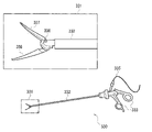
- FIG. 1 is a configuration example of a system 10 in this embodiment.
- FIG. 1 shows an example of a system configuration for photographing an operative field with an endoscope.
- System 10 shown in FIG. 1 includes controller 100 , endoscope system 200 , generator 300 and energy device 310 .
- System 10 is a surgical system for performing surgery using at least one energy device under an endoscope. Although an example in which the system 10 includes one energy device 310 is shown here, the system 10 may include multiple energy devices.
- the endoscope system 200 is a system that performs imaging with an endoscope, image processing of endoscopic images, and monitor display of endoscopic images.
- the endoscope system 200 includes an endoscope 210 , a main unit 220 and a display section 230 .
- a rigid endoscope for surgical operation will be described as an example.
- the endoscope 210 includes an insertion section to be inserted into a body cavity, an operation section connected to the proximal end of the insertion section, a universal cord connected to the proximal end of the operation section, and connected to the proximal end of the universal cord. and a connector portion.
- the insertion section includes a rigid tube, an objective optical system, an imaging device, an illumination optical system, a transmission cable, and a light guide.
- An objective optical system and an imaging element for photographing the inside of the body cavity, and an illumination optical system for illuminating the inside of the body cavity are provided at the distal end of an elongated cylindrical rigid tube.
- the distal end of the rigid tube may be configured to be bendable.
- a transmission cable that transmits an image signal acquired by the imaging element and a light guide that guides illumination light to the illumination optical system are provided inside the rigid tube.
- the operation unit is held by a user and receives operations from the user.
- the operation unit is provided with buttons to which various functions are assigned.
- the operation section is provided with an angle operation lever.
- the connector section includes a video connector that detachably connects a transmission cable to main device 220 and a light guide connector that detachably connects a light guide to main device 220 .
- the main device 220 includes a processing device that performs endoscope control, image processing of an endoscopic image, and display processing of an endoscopic image, and a light source device that generates and controls illumination light.
- the main unit 220 is also called a video system center.
- the processing device is composed of a processor such as a CPU, performs image processing on an image signal transmitted from the endoscope 210 to generate an endoscopic image, and outputs the endoscopic image to the display unit 230 and the controller 100. .
- the illumination light emitted by the light source device is guided by the light guide to the illumination optical system and emitted from the illumination optical system into the body cavity.
- the energy device 310 outputs energy such as high-frequency power or ultrasonic waves from its tip, and performs treatments such as coagulation, sealing, hemostasis, incision, dissection, or ablation on the tissue with which the tip is in contact.
- the energy device 310 is also called an energy treatment instrument.
- the energy device 310 includes a monopolar device that applies high-frequency power between the electrode at the tip of the device and an electrode outside the body, a bipolar device that applies high-frequency power between two jaws, a probe and jaws, and ultrasonic waves from the probe.
- An ultrasound device that emits ultrasonic waves, or a combination device that applies high-frequency power between a probe and a jaw and emits ultrasonic waves from the probe.
- the generator 300 supplies energy to the energy device 310 , controls the energy supply, and acquires electrical information from the energy device 310 .
- Generator 300 adjusts the output of energy device 310, for example, based on settings made by a physician.
- the generator 300 supplies energy corresponding to the doctor's setting to the energy device 310, and the energy device 310 receives the energy supply and outputs energy.
- the generator 300 supplies RF power and the energy device 310 outputs that RF power from the electrodes or jaws.
- the energy device 310 outputs ultrasonic energy
- the generator 300 supplies power, and the probe of the energy device 310 converts that power into ultrasound and outputs it.
- the electrical information is the electrical information of the tissue with which the electrodes or jaws of the energy device 310 are in contact. Specifically, it is the information obtained as a response to the energy device 310 outputting high-frequency power to the tissue. Electrical information is, for example, impedance information of tissue treated by energy device 310 . However, electrical information is not limited to impedance information.
- the generator 300 performs control to temporally change the energy output from the energy device 310 according to the output sequence.
- Generator 300 may vary its energy output in response to changes in impedance information over time.
- the output sequence may define how the energy output varies with changes in the impedance information.
- the generator 300 may automatically turn off the energy output according to the temporal change of the impedance information. For example, the generator 300 may determine that the treatment is completed and turn off the energy output when the impedance rises above a certain level.
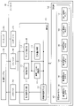
- Controller FIG. 2 is a configuration example of the controller 100 .
- Controller 100 includes control unit 110 , storage unit 120 and I/O devices 170 , 180 , 190 .
- the controller 100 controls the endoscope system 200, the generator 300, and the like of the system 10.
- FIG. For example, various controls are executed by image recognition processing using machine learning or the like.
- 1 and 2 show an example in which the controller 100 is configured as a separate device from the generator 300.
- the controller 100 is configured by an information processing device such as a PC or a server device.
- the controller 100 may be realized by, for example, a cloud system such as a system in which one or more information processing devices connected via a network execute processing.
- the control unit 110 recognizes at least one of tissue information or treatment information, which is information relating to treatment of a living tissue, from an endoscopic image by image recognition processing using the trained model 121, and based on this image recognition information. to output an energy output adjustment instruction.
- the energy output adjustment instruction may be an instruction based on the operator's operation.
- Control unit 110 includes one or more processors as hardware.
- the processor is a general-purpose processor such as a CPU (Central Processing Unit), GPU (Graphical Processing Unit) or DSP (Digital Signal Processor).
- the processor may be a dedicated processor such as an ASIC (Application Specific Integrated Circuit) or FPGA (Field Programmable Gate Array).
- the storage unit 120 stores a trained model 121 used for image recognition processing.
- storage unit 120 stores a program describing an inference algorithm and parameters used in the inference algorithm as trained model 121 .
- the storage unit 120 stores parameters used in the inference algorithm as a trained model 121 .
- Trained models 121 include first trained model 122 , second trained model 123 , third trained model 124 , fourth trained model 125 , fifth trained model 126 and sixth trained model 127 .
- Each trained model is used in each stage of the thermal diffusion region estimation process performed by this system, as will be described later with reference to FIG.
- the storage unit 120 is a storage device such as a semiconductor memory, hard disk drive, or optical disk drive.
- the semiconductor memory may be RAM, ROM, non-volatile memory, or the like.
- a neural network for example, can be used as an inference algorithm for image recognition processing. Weighting factor and bias of node-to-node connection in neural network are parameters.
- a neural network consists of an input layer that receives image data, an intermediate layer that performs arithmetic processing on the data input through the input layer, and an output layer that outputs recognition results based on the operation results output from the intermediate layer. ,including.
- a neural network used for image recognition processing for example, a CNN (Convolutional Neural Network) can be employed.
- the control unit 110 also includes a tissue detection unit 111, a device detection unit 112, a tissue tension evaluation unit 113, a grip force evaluation unit 114, a grip amount evaluation unit 115, a heat invasion region prediction unit 116, and an output image generation unit 117.
- the storage unit 120 stores the functions of the tissue detection unit 111, the device detection unit 112, the tissue tension evaluation unit 113, the grip force evaluation unit 114, the grip amount evaluation unit 115, the thermal invasion area prediction unit 116, and the output image generation unit 117. Store the written program.
- One or a plurality of processors of the control unit 110 reads out the program from the storage unit 120 and executes the program, whereby the device detection unit 112, the tissue tension evaluation unit 113, the grip force evaluation unit 114, the grip amount
- the functions of the evaluation unit 115, the thermal invasion area prediction unit 116, and the output image generation unit 117 are implemented.
- a program describing the function of each unit can be stored in a non-temporary information storage medium that is a computer-readable medium.
- the information storage medium can be implemented by, for example, an optical disc, memory card, HDD, semiconductor memory, or the like.
- the semiconductor memory is for example ROM or non-volatile memory.
- the I/O device 180 receives image data of endoscopic images from the main unit 220 of the endoscope system 200 . Also, the I/O device 190 transmits a signal representing the output result of the control unit 110 to the display unit 230 .
- the I/O devices 180 and 190 are connectors to which cables for image transmission are connected, or interface circuits connected to the connectors to communicate with the main unit 220 .
- the I/O device 170 transmits to the generator 300 a signal regarding energy output adjustment instructions and the like.
- the energy output adjustment instruction is, for example, an instruction based on image recognition information or an operator's operation.
- the I/O device 170 receives signals regarding setting information of the generator 300 and the like.
- the I/O device 170 is a connector to which a signal transmission cable is connected, or an interface circuit connected to the connector to communicate with the generator 300 .
- FIG. 3 is a flow chart explaining the processing performed by the controller 100 and the system 10.
- FIG. 3 is a flow chart explaining the processing performed by the controller 100 and the system 10.
- step S1 the control unit 110 acquires an endoscopic image and energy output setting information.
- Endoscope images can be acquired by the control unit 110 from the main unit 220 of the endoscope system 200 via the I/O device 180 .
- An endoscopic image is an image in which at least one energy device 310 and at least one living tissue are captured, and is an image captured before the energy of the energy device 310 is applied. It is an image imaged by.
- the image is also referred to as a pretreatment image.
- the camera that images the operative field is, for example, the endoscope 210, but is not limited to this.
- the image shown in FIG. 4 is an example of a pretreatment image.
- a bipolar device is shown as the energy device 310, and arteries and the like are shown as living tissue.
- the energy output setting information can be acquired by the control unit 110 from the generator 300 via the I/O device 170 .
- the energy output setting information is, for example, information such as energy level and energy sequence. In this way, in step S1, the control unit 110 acquires information on the energy supply amount of the energy device 310.
- control unit 110 executes steps S2A and S2B.
- step S2A control unit 110 detects tissue with tissue detection unit 111 based on the pretreatment image.
- step S2B the control unit 110 detects the jaws 337 and 338 with the device detection unit 112 based on the pretreatment image. Jaws 337 and 338 will be described later in FIG.
- step S3A1 the tissue tension evaluation unit 113 evaluates the tension applied to the tissue to be cut based on the detection results of steps S2A and A2B.
- the tissue to be cut refers to a tissue that the doctor grasps with the energy device 310 and intends to output energy.
- the tension applied to the tissue to be cut refers to the stress applied to the tissue grasped by the energy device 310 . For example, if a portion of tissue is grasped and pulled by the energy device 310, the tissue will deform to stretch, which will increase the tension on the tissue. Tension is also described as tension.
- control unit 110 After executing step S3A1, control unit 110 causes gripping force evaluation unit 114 to estimate the gripping force based on step S3A1 in step S3A2.
- Grasping force is the force with which the energy device 310 grips the tissue to be cut with the tip portion, eg, jaws. Further, the control unit 110 executes step S3B in parallel with steps S3A1 and S3A2.
- step S3B the control unit 110 causes the gripping amount evaluation unit 115 to estimate the gripping amount based on the detection results of steps S2A and S2B.
- the gripping amount is the physical length or area of the gripped portion of the biological tissue gripped by the energy device 310, as will be described later with reference to FIG.
- the control unit 110 causes the thermal invasion area prediction unit 116 to determine the amount of energy to be applied when energy is applied based on information such as the tissue gripped, the amount gripped, the position gripped, the tissue state, the tissue tension, the device used, or the output setting. Predict the area of thermal invasion.
- a thermally invaded region is a region in which heat may diffuse when energy is supplied from the energy device 310, and the heat may cause some changes in living tissue. Specific examples include thermal damage such as denaturation of proteins in biological tissues and deactivation of intracellular enzymes.
- the heat invasion area will be referred to as a heat diffusion area as appropriate.
- the grasped position is the position of the portion of the biological tissue to be treated that is grasped by the energy device 310 .
- the grip position can be predicted based on the results of steps S2A and S2B.
- a tissue condition is a condition of tissue that can affect heat spreading by the energy device 310 .
- the tissue condition is, for example, the amount of tissue surrounding the tissue gripped by the jaws, the immersion amount of the tissue gripped by the jaws or its surrounding tissue, or the amount of fat in the tissue gripped by the jaws.
- the amount of immersion is the amount of liquid covering the tissue, for example, the amount of immersion by body fluids such as blood or lymph.
- the tissue state can be predicted based on the results of, for example, step S2A described above.
- the output setting is information about settings such as the energy level and energy sequence, and is information about the amount of energy supply.
- the control unit 110 can acquire information about this energy supply amount from the generator 300, for example.
- the tissue tension is as described above for the tissue tension to be treated, and can be obtained as a result of step S3A1.
- the gripped tissue can be obtained from step S2A, the device used can be obtained from step S2B, and the amount of grip can be obtained from step S3B.
- step S4 the control unit 110 estimates the estimated thermal diffusion region based on the pretreatment image, the information on the energy supply amount, and the learned model 121.
- the estimated thermal diffusion area is the range estimated to reach the energy after applying the energy of the energy device 310 on the pre-treatment image based on the energy supply amount.
- step S5 the control unit 110 creates an output image by superimposing the prediction of the thermal invasion area on the endoscopic image in the output image creation unit 117. Specifically, the prediction result of the thermal invasion area is superimposed on the endoscopic image by, for example, adding color and displayed.
- step S6 the control unit 110 displays the image on the display unit 230.
- the control unit 110 outputs information included in the image to the endoscope system 200 via the I/O device 190, and the image is displayed on the display unit 230 of the endoscope system 200.
- the display unit 230 is, for example, a monitor of a personal computer. In this manner, the controller 100 performs processing for superimposing the estimated thermal diffusion region on the captured image of the camera and displaying it on the display unit 230 .
- FIG. 5 is a configuration example of the monopolar device 320.
- the monopolar device 320 includes an elongated cylindrical insertion portion 322, an electrode 321 provided at the distal end of the insertion portion 322, an operation portion 323 connected to the proximal end of the insertion portion 322, an operation portion 323 and a connector (not shown). and a cable 325 connecting the .
- the connector is detachably connected to generator 300 .
- the high-frequency power output by the generator 300 is transmitted through the cable 325 and output from the electrode 321 .
- a counter electrode is provided outside the patient's body, and current is passed between the electrode 321 and the counter electrode. Thereby, high-frequency energy is applied to the tissue with which the electrode 321 is in contact, and Joule heat is generated in the tissue.
- Various shapes of electrodes are employed for the electrodes 321 depending on the content of the treatment.
- the monopolar device 320 can adjust the degree of coagulation and incision by changing the energization pattern. In general, the treatment target of the monopolar device 320 is the tissue with which the electrode 321 is in contact, but the surrounding tissue may be affected by the heat diffused around the tissue with which the electrode 321 is in contact.
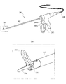
- FIG. 5 is a configuration example of the bipolar device 330.
- the bipolar device 330 includes an elongated cylindrical insertion portion 332, two jaws 337 and 338 provided at a distal end portion 331 of the insertion portion 332, an operation portion 333 connected to the proximal end of the insertion portion 332, and an operation portion 333. and a cable 335 connecting the connector (not shown).
- the connector is detachably connected to generator 300 .
- Jaws 337 and 338 are movable parts for gripping tissue and applying energy to the gripped tissue, and are configured to be openable and closable about an axis provided at proximal end 336 .
- the operation portion 333 is provided with a grip portion for opening and closing the jaws 337 and 338 . As the doctor squeezes the grasper, the jaws 337, 338 close and grasp the tissue.
- the high-frequency power output by the generator 300 is transmitted by the cable 335 and conducts electricity between the two jaws 337, 338 when the jaws 337, 338 grip the tissue.
- high-frequency energy is applied to the tissue sandwiched between the two jaws 337 and 338, generating Joule heat in the tissue and coagulating the tissue.
- the generator 300 may measure impedance information of the tissue grasped by the jaws 337, 338, detect treatment completion based on the impedance information, and automatically stop energy output.
- the generator 300 may also automatically adjust the energy applied to the tissue based on the impedance information. For example, although the device temperature of the bipolar device 330 rises only to about 100 degrees Celsius, there is a possibility that a stray current may occur around the portion gripped by the jaws 337 and 338, and the stray current may cause heat diffusion.
- a vessel sealing device is a device in which a cutter is provided on the jaw of a bipolar device. After coagulating tissue by energization, the tissue is cut by running the cutter.
- FIG. 7 is a configuration example of the ultrasonic device 340.
- the ultrasonic device 340 includes an elongated cylindrical insertion portion 342, a jaw 347 and a probe 348 provided at a distal end portion 341 of the insertion portion 342, an operation portion 343 connected to the proximal end of the insertion portion 342, and an operation portion 343. and a cable 345 connecting the connector (not shown).
- the connector is detachably connected to generator 300 .
- the jaw 347 is movable around an axis provided at the proximal end 346 and configured to be openable and closable with respect to the immovable probe 348 .
- the operation portion 343 is provided with a grip portion for opening and closing the jaws 347 .
- the operation unit 343 is provided with an operation button 344a to which the first output mode is assigned and an operation button 344b to which the second output mode is assigned.
- the output mode is selected according to the treatment content, and when the operation button for each output mode is pressed, ultrasonic energy is output in the output sequence of that mode.
- the power output by the generator 300 is transmitted by the cable 335, and when the operation button 344a or 344b is pressed, the probe 348 converts the power into ultrasonic waves and outputs them. As a result, frictional heat is generated in the tissue sandwiched between jaw 347 and probe 348, and the tissue is coagulated or dissected.
- the thermal diffusion of the ultrasonic device 340 is less than that of the high frequency device, but the device temperature of the ultrasonic device 340 rises to nearly 200 degrees Celsius. Thermal diffusion of the ultrasonic device 340 tends to occur in the tip direction of the probe 348 .
- a combination device that uses both high-frequency power and ultrasonic waves has the same configuration as the ultrasonic device in FIG. 6, for example.
- the combination device can generate Joule heat in the tissue gripped by the jaw and the probe by applying high-frequency power between the jaw and the probe, and coagulate the tissue. Further, the combination device can incise the tissue gripped by the jaws and the probe by outputting ultrasonic waves from the probe, like the ultrasonic device.
- a high frequency mode is assigned to one of the two operation buttons provided on the operation unit, and a seal & cut mode is assigned to the other.
- the high-frequency mode is a mode in which treatment such as coagulation is performed only by high-frequency energy output.
- the seal & cut mode is a mode that uses both high-frequency energy and ultrasonic energy, and is a mode that coagulates and cuts tissue by outputting high-frequency energy.
- thermal diffusion of combination devices for example, thermal diffusion similar to bipolar devices, thermal diffusion similar to ultrasonic devices, or both may occur.
- the bipolar device 330 is mainly used as the energy device 310 will be described as an example. However, this embodiment is applicable when using various energy devices described above in which thermal diffusion may occur.
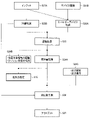
- FIG. 8 shows a first embodiment of a processing example of this system.
- the control unit 110 executes the processes shown in S21A and S21B. Specifically, in the input shown in S21A, the control unit 110 acquires a pretreatment image. Then, in S21B, the control unit 110 acquires the device type. The device type can be acquired from information detected by the device detection unit 112 . Then, in S21A, the control unit 110 inputs the acquired pretreatment image as output information to the device detection unit 112 that performs the processing of S22A and the tissue detection unit 111 that performs the processing of S22B. Also, in S22B, the control unit 110 inputs the acquired information about the device type to the device detection unit 112 that performs the processing of S22A as output information.
- the control unit 110 executes the processes shown in S22A and S22B.
- the energy device 310 is recognized.
- the device detection unit 112 detects the energy device 310 from the pretreatment image by executing an estimation program adjusted by machine learning.
- the estimation program is a program that executes the trained model 121 that has learned to estimate the type of the energy device 310 from the subject captured in the pretreatment image, as will be described later with reference to FIG. 12 .
- the device detection unit 112 detects the energy device 310 by inputting the intraoperative pretreatment image acquired in S21A to the network having the estimation program.
- information on the type of device acquired in S21B or information on the amount of energy supplied may be input to the network together with the pretreatment image.
- Targets to be estimated in the processing shown in S22A include, in addition to the type of the energy device 310, information such as the existence range of the energy device 310 or the state of its tip portion.
- the state of the tip portion is, for example, the opened/closed state of the jaws 337 and 338 .
- Information about these energy devices 310 is called device information.
- the device detection unit 112 labels, for example, by adding a color to the region of the detected energy device 310 on the pretreatment image.
- the tissue detection unit 111 of the control unit 110 recognizes the tissue of the control unit 110.
- the tissue detection unit 111 detects living tissue from the pretreatment image by executing an estimation program.
- the estimation program is a program that executes a trained model 121 that has learned to estimate the type of body tissue from the subject captured in the pretreatment image.
- the tissue detection unit 111 detects tissue information by inputting the pretreatment image acquired in S21A to the network having the estimation program.
- the tissue information includes the type of living tissue shown in the pretreatment image, the existence range of each tissue, the state of the tissue, and the like.
- the state of the tissue includes, for example, whether the tissue is wet or dry, and whether the tissue is discolored or not.
- Biological tissues include, for example, large blood vessels, pancreas, duodenum, etc., as well as tissues such as blood vessels such as sites connecting various tissues, arteries, and veins. A living tissue is also simply described as a tissue. Then, the type of biological tissue detected above is labeled. Labeling is performed, for example, by coloring a part, which is a region of a certain biological tissue.
- the images shown in FIG. 9 are examples of labeled images of the energy device 310 detected in S24A and S24B and the treatment target tissue. In the image shown in FIG.
- each of the energy device 310 and the tissue to be treated is labeled with a frame, and textual information is attached.
- the tissue to be treated is an artery, and the state of the tissue is displayed as dry.
- the tissue detection unit 111 extracts from the pretreatment image tissue information, which is information relating to the living tissue imaged on the pretreatment image.
- the pre-treatment image labeled in S22A and S22B becomes the recognition result in S23.
- the control unit 110 inputs the recognition result to the tissue tension evaluation unit 113 that performs the processing of S24A and the grip amount evaluation unit 115 that performs the processing of S24B.
- the input of the device type in S22A and the input of the tissue information in S22B may be manually input by the doctor. Further, in the tissue recognition in S22B, it is also possible to detect living tissue by 3D matching with CT (Computed Tomography) or MRI (Magnetic Resonance Imaging) instead of endoscopic images.
- CT Computer Tomography
- MRI Magnetic Resonance Imaging
- the control unit 110 executes S24A, S24B and S24C.
- the gripping amount evaluation unit 115 estimates the gripping amount of the tissue to be treated.
- the grasp amount evaluation unit 115 executes an estimation program to estimate the grasp amount of the tissue to be treated based on the recognition result of S23.
- the estimation program is a program that executes the trained model 121 that has learned to estimate the grasp amount of the tissue to be treated based on the information about the energy device 310 and the information about the living tissue.
- the amount of grasping is determined, for example, by the size of overlap between segmented subjects.
- the grasped amount evaluation unit 115 calculates the grasped amount of the tissue from the recognized image by inputting the information of the recognition result of S23 to the network having the estimation program.
- the gripping amount of the tissue is the physical length or area of the gripped portion of the biological tissue gripped by the energy device 310 .
- the grasping amount of the tissue detected above is labeled.
- the image shown in FIG. 10 is an example of an image labeled with the tissue gripping amount estimated in S24A by the gripping amount evaluation unit 115 .
- the amount of tissue gripped is labeled by displaying the portion gripping the tissue at the distal end of the energy device 310 so as to be surrounded by a frame. Note that the labeling method is not limited to the example shown in FIG.
- the grasp amount evaluation unit 115 inputs information including the labeled image to the thermal invasion area prediction unit 116 that performs the process of S26.
- the tissue tension evaluation unit 113 recognizes the tension state of the treatment target tissue. Specifically, the tissue tension evaluation unit 113 executes an estimation program to estimate the tension state of the treatment target tissue based on the recognition result of S23.
- the estimation program is a program that executes a trained model 121 that has learned to estimate the tension state of the tissue to be treated from the information on the energy device 310 in S23 and the information on the living tissue. is. If the tension is loose, it may be difficult to cut the tissue and the heat may spread, which may affect the result of estimating the thermal diffusion area.
- the tension is as described with reference to FIG.
- the tension of the tissue to be treated is also referred to as the tension applied to the living tissue.
- the tissue tension evaluation unit 113 estimates the tension state of the treatment target tissue from the recognized image by inputting the information of the recognition result of S23 to the network having the estimation program. For estimation of the tension state, for example, in the learning stage, it is learned that when a certain tissue is tensioned, it looks like this for each of various cases, and it is calculated backward from the pretreatment image acquired in the actual surgery. , to estimate how much tension is applied to the currently grasped tissue. Then, the tissue tension evaluation unit 113 inputs information about the estimated tension state to the grip force evaluation unit 114 that performs the process of S25 and the heat invasion region prediction unit 116 that performs the process of S26.
- the control unit 110 acquires information about output settings and output history.
- the output setting is the same as the output setting information described with reference to FIG.
- the output history is history information about the energy level output by the energy device 310, output settings, and the like. For example, the amount of residual heat, or information such as how many times the energy device 310 cuts the hair before treatment is performed. For example, immediately after turning off the output of the energy device 310, heat may still remain. Therefore, since the initial conditions for heat diffusion are different, the heat diffusion areas are also different. From this point of view, the output history is important in estimating the heat diffusion area. These information can be obtained from the generator 300, for example. Then, the control unit 110 inputs information about the acquired output setting and output history to the heat invasion area prediction unit 116 .
- the control unit 110 estimates the gripping force shown in S25.
- the gripping force evaluation unit 114 estimates the tissue gripping force of the energy device 310 by executing an estimation program.
- the estimation program is a program that executes the trained model 121 that has learned to estimate the tissue gripping force based on the tissue tension state information estimated in S24B.
- the gripping force evaluation unit 114 estimates the gripping force by inputting information on the tissue tension state to the network having the estimation program.
- the method of estimating the gripping force is, for example, the amount of change in the tissue around the gripped portion before and after gripping, such as size, color, reflectance, etc., and the amount of change applied by the energy device 310 in the learning stage. In advance, learn the relationship between grip strength. Then, the grasping force is estimated from the history of pre-treatment images acquired in actual surgery.
- the gripping force evaluation unit 114 inputs information including the estimation result to the thermal invasion area prediction unit 116 that performs the process of S26.
- control unit 110 predicts the thermal diffusion area as shown in S26.
- thermal invasion area prediction unit 116 of control unit 110 executes an estimation program to estimate the range of thermal diffusion when energy device 310 outputs energy.
- the estimation program estimates the thermal diffusion range based on information about the type and tension state of the tissue to be treated, the amount and force of gripping the tissue by the energy device 310, and the output setting and output history of the energy device 310. It is a program that executes a trained model 121 that has been trained as follows.
- the thermal invasion area prediction unit 116 estimates the thermal diffusion area from the recognized image by inputting the information into the network having the estimation program.
- the thermal diffusion area is as described in step S4 of FIG.
- the control unit 110 estimates the estimated thermal diffusion area in the treatment target tissue treated by the energy device 310 based on the pretreatment image, the information on the energy supply amount, and the learned model 121 .
- the image shown in FIG. 11 is an example of an image in which the thermal diffusion regions estimated in S26 are labeled.
- a heat spreading region is shown encircled around the jaws of the tip of the energy device 310 .
- the labeling of the heat spreading areas on the screen may be indicated by adding colors.
- the thermal invasion region prediction unit 116 inputs information including the labeled image to the output image generation unit 117 that performs the processing of S27.
- control unit 110 performs the output shown in S27.
- the output image creation unit 117 of the control unit 110 creates an image to be displayed on the display unit 230 of the endoscope system 200 based on information including the image created by the thermal invasion region prediction unit 116 in S26. I do. For example, information such as the energy device 310 and the tissue recognized in S22A and S22B, or the amount of grip recognized in S24A is displayed superimposed on the labeled image of the thermal diffusion region in S26 to create an output image. In this way, the output image creating unit 117 superimposes the estimated thermal diffusion area on the estimated area of the biological tissue around the energy device 310 and displays it.
- the superimposed display of the estimated heat diffusion area may be superimposed on the energy device 310 .
- the output image creation unit 117 inputs output information including the output image created in this manner to the endoscope system 200 via the I/O device 190 . By displaying the output image on the display unit 230 of the endoscope system 200, it is possible to present the thermal diffusion region to the doctor.
- FIG. 12 is a configuration example of a learning device 500 that performs machine learning for this system.
- Learning device 500 includes a processing unit 510 and a storage unit 520 .
- the learning device 500 is realized by, for example, an information processing device such as a PC or a server device.
- learning device 500 may be realized by a cloud system in which processing is executed by one or more information processing devices connected via a network.
- the processing unit 510 is a processor such as a CPU
- the storage unit 520 is a storage device such as a semiconductor memory or hard disk drive.
- the storage unit 520 stores teacher data 521 and learning models 522 .
- the teacher data 521 includes first teacher data 521A, second teacher data 521B, third teacher data 521C, fourth teacher data 521D, fifth teacher data 521E and sixth teacher data 521F.
- Learning models 522 also include a first learning model 522A, a second learning model 522B, a third learning model 522C, a fourth learning model 522D, a fifth learning model 522E, and a sixth learning model 522F.
- the processing unit 510 generates the trained model 121 by making the learning model 522 learn using the teacher data 521 .
- the teacher data 521 is a learning device tissue image that is an image of at least one biological tissue and at least one energy device 310 that receives energy supply and outputs energy, or an image of at least one biological tissue. , including training tissue images. Correct data is attached to each of the learning device tissue image and the learning tissue image. Correct data are annotations in segmentation (region detection) in machine learning, annotations in detection (position detection), correct labels in classification, or correct labels in regression (regression analysis). In the following description, the learning device tissue image and the learning tissue image are collectively referred to as the learning image.
- the first teacher data 521A is the teacher data 521 about the energy device 310.
- the second teacher data 521B, the third teacher data 521C, the fourth teacher data 521D, the fifth teacher data 521E, and the sixth teacher data 521F are respectively the living tissue, the grip amount of the living tissue, the tension state of the living tissue, This is teaching data about the grasping force of living tissue and the thermal diffusion range.
- the learning model 522 also corresponds to this, and the first learning model 522A, second learning model 522B, third learning model 522C, fourth teacher data 521D, fifth teacher data 521E, and sixth teacher data 521F are each energy device 310, a learning model for the living tissue, the gripping amount of the living tissue, the tension state of the living tissue, the gripping force of the living tissue, and the thermal diffusion range.
- the processing unit 510 inputs a learning image, which is the first teacher data 521A for the energy device 310, to inference processing by the first learning model 522A for the energy device 310.
- feedback is provided to the first learning model 522A based on the error between the result of the inference processing and the first teacher data 521A.
- the first trained model 122 can be generated. In this way, it becomes possible to realize estimation of the energy device 310 with higher accuracy in various surgical situations.
- the processing unit 510 transfers the generated learned model 121 to the controller 100 , and the learned model 121 is stored in the storage unit 120 of the controller 100 .
- FIG. 13 is an explanatory diagram of the first trained model 122 used for estimation of the energy device 310 in the device detection section 112.
- the first training data 521A labeled with annotations corresponding to the energy device 310 and the pretreatment image showing the living tissue is fed back to the first learning model 522A.
- the existing first trained model 122 is modified and input to the controller 100 as a new first trained model 122 .
- the content of the annotation is correct data such as the type, position, existence range of the energy device 310 , or the configuration and state of the tip portion of the energy device 310 .
- FIG. 14 is an explanatory diagram of the second trained model 123 used for estimating the living tissue in the tissue detection unit 111.
- FIG. 13 in the learning device 500, the second training data 521B labeled with the annotation corresponding to the pretreatment image is fed back to the second learning model 522B, so that the existing second trained model 123 is corrected and input to the controller 100 as a new second trained model 123 .
- the content of the annotation is correct data such as the name of the tissue existing in the pretreatment image, the existence range of each tissue, and the state of each tissue.
- FIG. 15 is an explanatory diagram of the fourth trained model 125 used for estimating the tension applied to the treatment target tissue in the tissue tension evaluation unit 113.
- the fourth training data 521D labeled with the annotation corresponding to the pretreatment image is fed back to the fourth learning model 522D, thereby correcting the existing fourth trained model 125 and creating a new fourth training model 522D. It is input to the controller 100 as a trained model 125 .
- the content of the annotation is, for example, correct data such as the name of the tissue to be treated, the range in which it exists, and the amount of tension applied to that region.
- the fourth teacher data 521D of the tension application amount can be obtained from the settings of the energy device 310, for example.
- FIG. 16 is an explanatory diagram of the fifth trained model 126 used for gripping force estimation in the gripping force evaluation unit 114 .
- the existing fifth trained model 126 is corrected by feeding back the fifth teacher data 521E labeled with the annotation corresponding to the pretreatment image to the fifth learning model 522E, and the new fifth It is input to the controller 100 as a trained model 126 .
- the content of the annotation is, for example, correct data such as the amount of applied tension, the amount of tissue change around the gripping portion, and the gripping force.
- the tension application amount fifth teacher data 521E can be obtained, for example, from the settings of the energy device 310, as in the case of FIG.
- the grip force can also be obtained from the energy device 310 settings.
- the tissue change amount around the grip portion can be extracted, for example, from the history information of pretreatment images.
- FIG. 17 is an explanatory diagram of the sixth trained model 127 used for estimating the thermal diffusion area in the thermal invasion area prediction unit 116.
- the sixth teacher data 521F labeled with the annotation corresponding to the pretreatment image is fed back to the sixth learning model 522F to correct the existing sixth trained model 127 and create a new sixth training model 521F. It is input to the controller 100 as a trained model 127 .
- the contents of the annotation are, for example, correct data such as tissue type, state, grip amount, tissue tension application amount, grip force, output setting, type of energy device 310, output history, thermal diffusion area after treatment, and the like.
- a part of the correct data may be labeled by, for example, a doctor.
- a key point in performing energy treatment in surgery is to suppress heat diffusion from the energy device to avoid thermal damage to surrounding organs.
- the tissue to be treated is not uniform, and the time required for treatment such as cutting varies due to differences in tissue types, differences in tissue conditions, individual differences among patients, etc., and the degree of thermal diffusion also varies.
- doctors adjust the amount of tissue gripping and tissue tension by energy devices, but it is sometimes difficult for inexperienced non-experts to make appropriate adjustments. Therefore, in order to proceed with the procedure efficiently, it is desirable to have support from the system.
- Patent Document 1 a region of a living tissue that has been ablated and a region of a living tissue that has not been ablated are displayed on a display, and the next area of the living tissue to which energy should be output is presented to the doctor.
- the temperature change is estimated and output from the difference between the CT images before the energy output and after the energy output is started, only the temperature change after the start of the heat output can be estimated. cannot be presented.
- the thermal diffusion area is estimated based on information such as the energy device and biological tissue, and the estimated thermal diffusion area is displayed superimposed on the screen.
- the doctor can know the heat diffusion area in advance, and can set the output of the energy device so as not to thermally damage the tissue to be treated.
- this system by estimating the thermal diffusion area using machine learning, safe and efficient surgery can be realized regardless of the experience of the doctor, and the stability of surgery can be improved.
- FIG. 18 is a configuration example of a controller 100 in a second embodiment of this system.
- the second embodiment differs from the first embodiment shown in FIG. Specifically, in the first embodiment, the information input to the grip force evaluation unit 114 is output from the tissue tension evaluation unit 113 and the grip amount evaluation unit 115, but in the second embodiment, the grip force evaluation Information input to the unit 114 is output from a generator 300 external to the controller 100 . That is, in the second embodiment, the gripping force evaluation unit 114 detects the gripping force of the energy device 310 by acquiring information from the generator 300 outside the controller 100 .
- the generator 300 can, for example, acquire a gripping force detection value from a gripping force detection sensor such as a stress sensor or a position meter mounted on the handle of the energy device 310 . Then, the control unit 110 estimates the estimated thermal diffusion region based on the pretreatment image, the information on the energy supply amount, and the gripping force acquired from the gripping force detection sensor.
- a gripping force detection sensor such as a stress sensor or a position meter mounted on the handle of the energy device 310 .
- FIG. 19 shows a processing example of the second embodiment of this system.
- the gripping force estimation in S25 is changed to gripping force measurement shown in S34C in FIG.
- the grip force evaluation unit 114 does not obtain the output result of the tissue tension evaluation unit 113, but obtains the detected value of the grip amount from an external device such as the generator 300, for example.
- the estimation process in the grip force evaluation unit 114 can be skipped. Therefore, the estimation processing of the thermal diffusion region can be speeded up.
- the degree of certainty of the underlying data is low. In such a case, even if the estimation process is carried out over a long period of time, the confidence level of the estimation result may also be low. Surgery becomes difficult to achieve. Therefore, according to the second embodiment, it is possible to realize efficient surgery while maintaining safety.
- FIG. 20 is a configuration example of a controller 100 in a third embodiment of this system.
- the third embodiment differs from the second embodiment shown in FIG. 18 in that the tissue tension evaluation unit 113 is not provided. That is, in the third embodiment, the thermal diffusion region is estimated without estimating the tissue tension by machine learning. Then, a thermal diffusion region that changes depending on the amount of applied tissue tension, ie, the tension applied to the living tissue, is superimposed and displayed on the screen. For example, both the predicted range of thermal diffusion when the tension is strong and the predicted range of thermal diffusion when the tension is weak are presented. Also, with respect to the intensity of tension, an estimated heat diffusion region corresponding to each of a plurality of stages may be estimated. In this case, the multiple steps may be gradations.
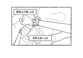
- FIG. 21 is an example of an image in which the estimated thermal diffusion regions for strong tension and weak tension are displayed superimposed on the pre-treatment image by applying the third embodiment.
- the estimated heat diffusion area is displayed in a small area on either side of the jaw at the distal end of the energy device 310 .
- the tension applied to the tissue is weak, the estimated heat diffusion area is displayed in a wide range on both sides of the jaw.
- FIG. 22 shows a processing example of the third embodiment. Compared to the processing example of the first embodiment shown in FIG. 3 described above, there is no step of evaluating the tension applied to the tissue in step S3A1. Moreover, there is no step of estimating the gripping force in the gripping force evaluation unit 114 shown in S3A2 in FIG. Furthermore, in the third embodiment shown in FIG. 22, in step S45, prediction of the thermal invasion area is superimposed on the endoscopic image for each amount of tension applied to the tissue.
- the estimation processing in the tissue tension evaluation unit 113 and the grip force evaluation unit 114 can be skipped. Therefore, compared with the case of the second embodiment, the estimation processing of the thermal diffusion area can be further speeded up.
- control unit 110 does not estimate the grip amount of the energy device 310 captured in the pre-treatment image, and estimates thermal diffusion corresponding to each stage of a plurality of stages of the grip amount. A region may be estimated. By doing so, the estimation processing in the grip amount evaluation unit 115 can be skipped, and the estimation processing of the estimated thermal diffusion region can be speeded up.
- the confidence of the estimated values of the tension and the grasping amount is When it is lower than a predetermined value, the best case and the worst case of the tension and gripping amount may be displayed. Also, in this case, for each parameter, an estimated thermal diffusion region corresponding to each of the plurality of stages may be estimated. That is, in the fourth embodiment, for example, when the confidence in estimating the tension applied to the tissue is lower than the first predetermined value, the estimated tension is not used, and the estimation corresponding to each of the plurality of stages of tension is performed. Estimate the heat diffusion area.
- the first predetermined value and the second predetermined value are reference values that are recognized as inappropriate for use in estimating the estimated heat diffusion region because the confidence of the tension value estimated by machine learning is low. can be set arbitrarily. According to this embodiment, the doctor can select an appropriate energy setting from the displayed information of the estimated heat diffusion area at each stage, and can safely and efficiently perform surgery.
- the fourth embodiment if the certainty factor of a parameter other than the tension or gripping amount is lower than a predetermined value, the estimated value of that parameter may not be used for estimating the estimated thermal diffusion region. It should be noted that the fourth embodiment may be applied when both the tension and the amount of gripping, or one of them has a low degree of certainty. Also, the first predetermined value and the second predetermined value may be the same or different.
- control unit 110 may estimate an estimated heat diffusion area for each temperature or heat, and display the estimated heat diffusion area for each temperature or heat by superimposing it on the pretreatment image. That is, the control unit 110 can superimpose and display the estimated heat diffusion area around the recognized energy device 310 and living tissue while color-coding each variable, temperature, and heat.
- the color for example, it is possible to display with an intermediate color between the display color of the tension and the display color of the gripping force.
- warm colors are used for tension, such as red when the tension is strong and orange when the tension is weak. Let's assume that it was a cool color, such as navy blue when it was weak.
- the estimated heat diffusion regions are displayed in a neutral color by integrating them. Then, it is possible to indicate that the accuracy of the tension and gripping force parameters is insufficient.
- the best mode is the estimated heat diffusion area, and the estimated heat diffusion area is the narrowest. can be displayed.
- the doctor can know which parameter has a low degree of certainty, and can use colors to indicate what combinations of parameters with a low degree of certainty can achieve the best mode. be able to make decisions based on When there are multiple parameters with low confidence, it is not easy for the doctor to determine what combination of parameter settings should be used to minimize the thermal diffusion area. Therefore, in this way, machine learning can be used to present a combination that minimizes the thermal diffusion area among possible combinations of parameters, thereby supporting the doctor's decision.
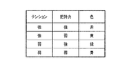
- FIGS. 24 and 25 are examples in which, when there are multiple parameters with low confidence, the corresponding colors are set and displayed on the screen for all possible combinations of the setting values of the parameters.
- FIG. 24 shows all possible combinations of tension and gripping force when setting values are strong or weak, and colors corresponding to the combinations.
- FIG. 25 is an example of an image showing, in corresponding colors, how the estimated thermal diffusion regions are distributed when the combinations of parameters shown in FIG. 24 are applied. In the case shown in FIG. 25, it can be seen that the estimated heat diffusion area is narrowest when both the tension and the gripping force are strong.
- FIG. 26 is a configuration example of a controller 100 in a fifth embodiment of this system.
- the fifth embodiment differs from the first embodiment shown in FIG. 2 in that there is no grip force evaluation unit 114 . That is, in the fifth embodiment, the thermal diffusion area is estimated without estimating the gripping force by machine learning. Then, the thermal diffusion area that changes depending on the gripping force is displayed superimposed on the screen.
- the grip force information is input to the fifth teacher data 521E, and the estimated heat diffusion region for various grip forces is estimated and superimposed on the pretreatment image.
- FIG. 27 is an example of an image in which the estimated thermal diffusion regions for strong grip force and weak grip force are displayed superimposed on the pre-treatment image by applying the fifth embodiment. In the case shown in FIG.
- the estimated heat diffusion area is displayed in a narrow range on both sides of the jaw at the tip of the energy device 310 .
- the gripping force is weak, the estimated heat diffusion area is displayed in a wide range on both sides of the jaw.
- an estimated heat diffusion region corresponding to each of a plurality of stages may be estimated with respect to the magnitude of the gripping force.
- FIG. 28 is a flowchart for explaining the processing performed by the controller 100 and system 10 when the fifth embodiment is applied. Compared with the flowchart shown in FIG. 3, the step of estimating the grip force in the grip force evaluation unit 114 in step S3A2 of FIG. 3 is eliminated. As for step S5 in FIG. 3, in the fifth embodiment, an output image is created by superimposing the prediction of the thermal invasion area on the endoscopic image for each grip force applied to the tissue.
- the present system can be realized at low cost. Sterilization of the energy device 310 may also be facilitated.
- the estimated heat diffusion area is estimated without estimating the gripping force, but other parameters, such as the gripping amount of living tissue, can be similarly applied.
- FIG. 29 is an example of an image in which the estimated heat diffusion regions when the gripping amount is deep and when the gripping amount is shallow are superimposed and displayed in different patterns without estimating the gripping amount.
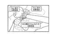
- FIG. 30 is a display example of the estimated thermal diffusion area when the sixth embodiment of the present system is applied.
- the estimated thermal diffusion regions 0.1 seconds, 5 seconds, and 10 seconds after the start of energy application are displayed superimposed on the endoscopic image.
- the estimated thermal diffusion area may expand in a short period of time depending on the heat conduction and tissue conditions of the tissue to be treated and its surrounding tissue. . Therefore, according to the sixth embodiment, the doctor can know how much the estimated thermal diffusion area expands when the energy is continuously applied, and the doctor can perform the surgery more safely and efficiently.
- the system of this embodiment can also be implemented as a program. That is, an image in which at least one energy device and at least one living tissue are imaged, and which is an image captured before energy is applied to the energy device, and is a pretreatment image captured by a camera that captures an image of the surgical field. to get information about the energy supply of the energy device.
- the computer is caused to superimpose the estimated heat diffusion region on the captured image of the camera and display it on the display unit.
- the computer is assumed to be a network terminal such as a personal computer.
- the computer may be a wearable terminal such as a smart phone, a tablet terminal, or a smart watch. By doing so, an effect similar to that described above can be obtained.
- the system of this embodiment can also be implemented as an information processing method. That is, the information processing method captures an image in which at least one energy device and at least one living tissue are imaged, and which is an image captured before energy is applied to the energy device, and is captured by a camera that captures an image of the surgical field. A pre-treatment image is obtained to obtain information regarding the energy delivery of the energy device.
- the system 10 of the present embodiment described above includes a storage unit 120 that stores a trained model 121 and a control unit 110.
- the trained model 121 is trained to output the heat diffusion area from the learning device tissue image or the learning tissue image.
- a learning device tissue image is an image of at least one energy device that receives energy supply and outputs energy and at least one living tissue.
- a learning device tissue image is an image obtained by capturing at least one living tissue.
- the control unit 110 captures an image in which at least one energy device and at least one living tissue are imaged before energy is applied to the energy device 310, and is captured by a camera that captures an image of the surgical field. Acquire a pre-treatment image.
- the control unit 110 acquires information on the energy supply amount of the energy device.
- the control unit 110 estimates that the energy will arrive after applying the energy of the energy device on the pre-treatment image based on the energy supply amount. Estimate the estimated thermal diffusion area, which is the range of The control unit 110 causes the display unit to display the estimated heat diffusion area superimposed on the image captured by the camera.
- the thermal diffusion area is estimated based on the pretreatment image and the information on the energy supply amount, and the estimated thermal diffusion area is superimposed and displayed on the screen.
- the doctor can know the thermal diffusion area in advance, and can set the output of the energy device 310 so as not to cause thermal damage to the tissue to be treated.
- the organization information is described, for example, in "1. System".
- control unit 110 extracts tissue information, which is information about the living tissue imaged on the pretreatment image, from the pretreatment image, and based on the tissue information and the information about the energy supply amount, An estimated heat diffusion area may be estimated.
- a treatment target tissue can be extracted by machine learning using pretreatment images. Therefore, the estimated heat diffusion area can be estimated based on this.
- control unit 110 extracts device information, which is information about the energy device 310 imaged on the pretreatment image, from the pretreatment image, and based on the device information and the tissue information, extracts energy An estimated heat diffusion area in the treated tissue treated by device 310 may be estimated.
- the tissue to be treated and the energy device 310 can be extracted by machine learning using the pretreatment image. Therefore, the estimated heat diffusion area can be estimated based on these pieces of information.
- the device information is described in "4. First Embodiment".
- control unit 110 estimates the regions of the treatment target tissue and the energy device 310 on the pretreatment image based on the tissue information and the device information. Based on the estimated treatment target tissue and the region of the energy device 310, the control unit 110 estimates at least one of the tension applied to the living tissue imaged in the pretreatment image and the grasp amount of the energy device as an estimation result. . The control unit 110 estimates the estimated heat diffusion area based on the estimation result, the tissue information, and the information on the energy supply amount.
- control unit 110 may estimate the gripping force of the energy device 310 based on the estimated tension and the pretreatment image, and estimate the estimated thermal diffusion area based on the estimated gripping force. .
- the gripping force of the energy device 310 can be estimated by machine learning based on the tension and the pretreatment image estimated by the control unit 110 . Therefore, the gripping force can be used to estimate the estimated heat diffusion area.
- control unit 110 acquires the gripping force detection value detected by the gripping force detection sensor provided in the gripping unit of the energy device 310, and determines the estimated thermal diffusion area based on the acquired detection value. can be estimated.
- the estimation processing in the gripping force evaluation unit 114 can be skipped by using the data measured by the gripping force detection sensor. Therefore, the estimation processing of the estimated thermal diffusion area can be speeded up.
- the degree of certainty of gripping force data which is the basis of estimation, is low, safe and efficient surgery can be achieved by using the data measured by the gripping force detection sensor.
- control unit 110 may estimate an estimated heat diffusion area for each temperature or heat, and display the estimated heat diffusion area for each temperature or heat by superimposing it on the pretreatment image.
- control unit 110 can superimpose and display the estimated thermal diffusion area around the recognized energy device 310 and living tissue in a color-coded manner for each variable, temperature, and heat.
- control unit 110 estimates the area of the biological tissue and the area of the energy device 310 from the pretreatment image, and superimposes the estimated thermal diffusion area on the estimated area of the biological tissue around the energy device 310. may be displayed.
- the area of the living tissue and the area of the energy device 310 can be estimated by machine learning from the pretreatment image. Therefore, it is possible to superimpose the estimated heat diffusion region on the pretreatment image.
- control unit 110 may estimate an estimated heat diffusion region corresponding to each of a plurality of stages of tension without estimating the tension applied to the living tissue captured in the pretreatment image.
- the estimation processing in the tissue tension evaluation unit 113 can be skipped. Therefore, the estimation processing of the estimated heat diffusion area can be speeded up. Note that the method of displaying the estimated heat diffusion area corresponding to each of the plurality of stages of tension is described in FIG. 21 of "6. Third Embodiment".
- control unit 110 does not estimate the gripping amount of the energy device 310 captured in the pre-treatment image, but estimates the estimated thermal diffusion region corresponding to each of the stages of the gripping amount. good too.
- the control unit 110 estimates the tension applied to the biological tissue captured in the pretreatment image and the gripping amount of the energy device 310 based on the pretreatment image.
- the control unit 110 does not use the estimated tension for estimating the estimated heat diffusion area, and calculates the estimated heat corresponding to each of the plurality of stages of the tension.
- Estimate the diffusion area When the certainty in estimating the gripping amount is lower than the second predetermined value, the control unit 110 does not use the estimated gripping force for estimating the estimated heat diffusion area, and responds to each of a plurality of stages of the gripping amount. Estimate the thermal diffusion area.
- the present embodiment it is possible to determine whether or not to use the estimated values for estimating the thermal diffusion area according to the degree of certainty of the estimated values of the tension and grip amount. Therefore, when the confidence of the estimated value is low, it becomes possible to estimate the thermal diffusion region corresponding to each of the plurality of stages of the tension and grip amount without using the estimated value. Therefore, the doctor can select an appropriate energy setting from the displayed information, and can perform surgery safely and efficiently.
- the first predetermined value and the second predetermined value are described in "7. Fourth Embodiment”.
- the method of displaying the estimated heat diffusion area corresponding to each of a plurality of stages of the tension and grip amount is described in FIG. 23 of "7. Fourth Embodiment”.
- control unit 110 may estimate an estimated thermal diffusion area corresponding to each of a plurality of stages of gripping force with which the energy device 310 grips the biological tissue.
- FIG. 27 shows a display example of the estimated heat diffusion area when this embodiment is used.
- control unit 110 may estimate the estimated heat diffusion area corresponding to each stage of a plurality of stages of time by the energy device 310 .
- the doctor can know how much the estimated thermal diffusion area expands when the energy is continuously applied, so that the doctor can perform surgery more safely and efficiently.
- the method of displaying the estimated heat diffusion area corresponding to each stage of a plurality of stages of time is shown in FIG. 30 of "9. Sixth Embodiment”.
- the above processing may be described as a program. That is, the program of the present embodiment acquires a pretreatment image, acquires information about the amount of energy supply, and performs processing based on the learned model 121 to determine an estimated thermal diffusion region where energy is estimated to reach.
- the controller 100 is caused to perform the estimation and the superimposition of the estimated thermal diffusion area on the captured image of the camera and display on the display unit.
- the above processing may be described as an information processing method. That is, the information processing method of the present embodiment acquires a pretreatment image, acquires information about the amount of energy supply, and estimates an estimated thermal diffusion region where energy is estimated to reach by processing based on the learned model 121. , the estimated heat diffusion area is superimposed on the captured image of the camera and displayed on the display unit.
Landscapes
- Engineering & Computer Science (AREA)
- Health & Medical Sciences (AREA)
- Medical Informatics (AREA)
- General Health & Medical Sciences (AREA)
- Public Health (AREA)
- Biomedical Technology (AREA)
- Life Sciences & Earth Sciences (AREA)
- Surgery (AREA)
- Physics & Mathematics (AREA)
- Nuclear Medicine, Radiotherapy & Molecular Imaging (AREA)
- Theoretical Computer Science (AREA)
- General Physics & Mathematics (AREA)
- Animal Behavior & Ethology (AREA)
- Veterinary Medicine (AREA)
- Epidemiology (AREA)
- Primary Health Care (AREA)
- Molecular Biology (AREA)
- Heart & Thoracic Surgery (AREA)
- Radiology & Medical Imaging (AREA)
- Computer Vision & Pattern Recognition (AREA)
- Otolaryngology (AREA)
- Pathology (AREA)
- Plasma & Fusion (AREA)
- Multimedia (AREA)
- Business, Economics & Management (AREA)
- General Business, Economics & Management (AREA)
- Quality & Reliability (AREA)
- Data Mining & Analysis (AREA)
- Databases & Information Systems (AREA)
- Biophysics (AREA)
- Robotics (AREA)
- Urology & Nephrology (AREA)
- Human Computer Interaction (AREA)
- Surgical Instruments (AREA)
- Endoscopes (AREA)
Priority Applications (2)
| Application Number | Priority Date | Filing Date | Title |
|---|---|---|---|
| JP2023535110A JP7465413B2 (ja) | 2021-07-13 | 2022-03-07 | システム、プログラム及び情報処理方法 |
| US18/237,732 US12593984B2 (en) | 2021-07-13 | 2023-08-24 | System, information storage medium, and information processing method |
Applications Claiming Priority (4)
| Application Number | Priority Date | Filing Date | Title |
|---|---|---|---|
| US202163221128P | 2021-07-13 | 2021-07-13 | |
| US63/221,128 | 2021-07-13 | ||
| US202163222252P | 2021-07-15 | 2021-07-15 | |
| US63/222,252 | 2021-07-15 |
Related Child Applications (1)
| Application Number | Title | Priority Date | Filing Date |
|---|---|---|---|
| US18/237,732 Continuation US12593984B2 (en) | 2021-07-13 | 2023-08-24 | System, information storage medium, and information processing method |
Publications (1)
| Publication Number | Publication Date |
|---|---|
| WO2023286335A1 true WO2023286335A1 (ja) | 2023-01-19 |
Family
ID=84919163
Family Applications (4)
| Application Number | Title | Priority Date | Filing Date |
|---|---|---|---|
| PCT/JP2022/009692 Ceased WO2023286335A1 (ja) | 2021-07-13 | 2022-03-07 | システム、プログラム及び情報処理方法 |
| PCT/JP2022/009691 Ceased WO2023286334A1 (ja) | 2021-07-13 | 2022-03-07 | システム、プログラム及びエネルギー出力調整方法 |
| PCT/JP2022/009693 Ceased WO2023286336A1 (ja) | 2021-07-13 | 2022-03-07 | システム、プログラム及び判定方法 |
| PCT/JP2022/009694 Ceased WO2023286337A1 (ja) | 2021-07-13 | 2022-03-07 | システム、プログラム及び情報処理方法 |
Family Applications After (3)
| Application Number | Title | Priority Date | Filing Date |
|---|---|---|---|
| PCT/JP2022/009691 Ceased WO2023286334A1 (ja) | 2021-07-13 | 2022-03-07 | システム、プログラム及びエネルギー出力調整方法 |
| PCT/JP2022/009693 Ceased WO2023286336A1 (ja) | 2021-07-13 | 2022-03-07 | システム、プログラム及び判定方法 |
| PCT/JP2022/009694 Ceased WO2023286337A1 (ja) | 2021-07-13 | 2022-03-07 | システム、プログラム及び情報処理方法 |
Country Status (3)
| Country | Link |
|---|---|
| US (5) | US12484788B2 (https=) |
| JP (4) | JP7465413B2 (https=) |
| WO (4) | WO2023286335A1 (https=) |
Families Citing this family (5)
| Publication number | Priority date | Publication date | Assignee | Title |
|---|---|---|---|---|
| JP7465413B2 (ja) | 2021-07-13 | 2024-04-10 | オリンパス株式会社 | システム、プログラム及び情報処理方法 |
| JP2025058623A (ja) * | 2023-09-28 | 2025-04-09 | オムロン株式会社 | モデル生成方法及び推論プログラム |
| WO2025115599A1 (ja) | 2023-11-28 | 2025-06-05 | オリンパスメディカルシステムズ株式会社 | 支援装置、支援方法および記録媒体 |
| EP4574007A1 (en) * | 2023-12-22 | 2025-06-25 | Olympus Winter & Ibe GmbH | Medical camera system and method for capturing images and processing said images |
| CN118680657B (zh) * | 2024-06-05 | 2025-06-13 | 河北壹雪制冷科技有限公司 | 一种基于传感反馈的冷冻笔控制装置 |
Citations (2)
| Publication number | Priority date | Publication date | Assignee | Title |
|---|---|---|---|---|
| JP2018511403A (ja) * | 2015-04-02 | 2018-04-26 | ハートフロー, インコーポレイテッド | 生体熱伝達の個人化推定を提供するシステム及び方法 |
| JP2019170809A (ja) * | 2018-03-29 | 2019-10-10 | 株式会社日立製作所 | 医療システム |
Family Cites Families (44)
| Publication number | Priority date | Publication date | Assignee | Title |
|---|---|---|---|---|
| JPH11197159A (ja) | 1998-01-13 | 1999-07-27 | Hitachi Ltd | 手術支援システム |
| JPH11267133A (ja) * | 1998-03-25 | 1999-10-05 | Olympus Optical Co Ltd | 治療装置 |
| US8398541B2 (en) | 2006-06-06 | 2013-03-19 | Intuitive Surgical Operations, Inc. | Interactive user interfaces for robotic minimally invasive surgical systems |
| US8048069B2 (en) | 2006-09-29 | 2011-11-01 | Medtronic, Inc. | User interface for ablation therapy |
| KR20130010952A (ko) * | 2011-07-20 | 2013-01-30 | 삼성전자주식회사 | 이중 에너지 엑스선 영상 장치 및 그 제어방법 |
| US9259287B2 (en) * | 2013-04-02 | 2016-02-16 | Siemens Aktiengesellschaft | Patient specific planning and simulation of ablative procedures |
| US20150272653A1 (en) | 2014-04-01 | 2015-10-01 | Siemens Medical Solutions Usa, Inc. | Thermal therapy ablation detection with ultrasound |
| CN106456242B (zh) | 2015-02-18 | 2019-09-03 | 奥林巴斯株式会社 | 关节用手术系统 |
| US9839483B2 (en) | 2015-04-21 | 2017-12-12 | Heartflow, Inc. | Systems and methods for risk assessment and treatment planning of arterio-venous malformation |
| JP2017006337A (ja) | 2015-06-19 | 2017-01-12 | ソニー株式会社 | 医療支援装置および方法、並びに、医療支援システム |
| JPWO2017090165A1 (ja) * | 2015-11-26 | 2018-08-30 | オリンパス株式会社 | 処置システム、及び処置具 |
| US10786298B2 (en) * | 2016-03-01 | 2020-09-29 | Covidien Lp | Surgical instruments and systems incorporating machine learning based tissue identification and methods thereof |
| US10537394B2 (en) | 2016-12-19 | 2020-01-21 | Ethicon Llc | Hot device indication of video display |
| US11908584B2 (en) | 2017-05-15 | 2024-02-20 | Ne Scientific, Llc | Methods and systems for modeling a necrotized tissue volume in an ablation procedure |
| WO2019046152A1 (en) | 2017-08-29 | 2019-03-07 | Intuitive Surgical Operations, Inc. | VISUAL DETECTION OF ELECTROCAUTERIZATION ARCS |
| US11051876B2 (en) | 2017-12-28 | 2021-07-06 | Cilag Gmbh International | Surgical evacuation flow paths |
| US11424027B2 (en) | 2017-12-28 | 2022-08-23 | Cilag Gmbh International | Method for operating surgical instrument systems |
| US11147607B2 (en) | 2017-12-28 | 2021-10-19 | Cilag Gmbh International | Bipolar combination device that automatically adjusts pressure based on energy modality |
| WO2019142252A1 (ja) | 2018-01-17 | 2019-07-25 | オリンパス株式会社 | 制御装置及び制御装置の作動方法 |
| EP3755258A1 (en) * | 2018-02-23 | 2020-12-30 | Biocompatibles UK Limited | Volumetric imaging |
| US12178514B2 (en) | 2018-02-23 | 2024-12-31 | Boston Scientific Scimed, Inc. | Volumetric imaging |
| US11523839B2 (en) | 2018-04-03 | 2022-12-13 | Intuitive Surgical Operations, Inc. | Systems and methods for grasp adjustment based on grasp properties |
| JP7104375B2 (ja) | 2018-07-09 | 2022-07-21 | 日本電気株式会社 | 施術支援装置、施術支援方法、及びプログラム |
| US10307209B1 (en) | 2018-08-07 | 2019-06-04 | Sony Corporation | Boundary localization of an internal organ of a subject for providing assistance during surgery |
| US11471206B2 (en) * | 2018-09-07 | 2022-10-18 | Cilag Gmbh International | Method for controlling a modular energy system user interface |
| CN112135575B (zh) | 2018-11-07 | 2024-06-21 | 奥林巴斯株式会社 | 医疗装置、余热判定方法以及余热判定程序 |
| EP3883489A1 (en) | 2018-11-20 | 2021-09-29 | Koninklijke Philips N.V. | Temporal mapping of thermal ablation areas |
| US11141231B2 (en) | 2018-12-13 | 2021-10-12 | Cilag Gmbh International | Surgical tool performance via measurement and display of tissue tension |
| US20220104884A1 (en) | 2019-02-08 | 2022-04-07 | The Board Of Trustees Of The University Of Illinois | Image-Guided Surgery System |
| US12333423B2 (en) | 2019-02-14 | 2025-06-17 | Covidien Lp | Systems and methods for estimating tissue parameters using surgical devices |
| JP6801897B2 (ja) | 2019-03-15 | 2020-12-16 | リバーフィールド株式会社 | 力覚表示装置および力覚表示方法 |
| US10758309B1 (en) | 2019-07-15 | 2020-09-01 | Digital Surgery Limited | Methods and systems for using computer-vision to enhance surgical tool control during surgeries |
| US20210038314A1 (en) * | 2019-08-11 | 2021-02-11 | phenoMapper, LLC | Method and System for Personalized Treatment Planning in Ablation of Cancerous Tissue |
| JP2021029258A (ja) | 2019-08-13 | 2021-03-01 | ソニー株式会社 | 手術支援システム、手術支援方法、情報処理装置、及び情報処理プログラム |
| JP2021029979A (ja) * | 2019-08-29 | 2021-03-01 | 国立研究開発法人国立がん研究センター | 教師データ生成装置、教師データ生成プログラム及び教師データ生成方法 |
| US20210085387A1 (en) * | 2019-09-22 | 2021-03-25 | Biosense Webster (Israel) Ltd. | Guiding cardiac ablation using machine learning (ml) |
| JP2021083969A (ja) | 2019-11-29 | 2021-06-03 | キヤノンメディカルシステムズ株式会社 | 医用画像処理装置、医用画像処理方法及び医用画像処理プログラム |
| JP7438731B2 (ja) * | 2019-11-29 | 2024-02-27 | キヤノンメディカルシステムズ株式会社 | 医用画像処理装置、医用画像処理装置の作動方法及び医用画像処理プログラム |
| US12303187B2 (en) | 2019-11-29 | 2025-05-20 | Canon Medical Systems Corporation | Medical image processing apparatus |
| US11284963B2 (en) | 2019-12-30 | 2022-03-29 | Cilag Gmbh International | Method of using imaging devices in surgery |
| EP3886039A1 (en) * | 2020-03-26 | 2021-09-29 | Koninklijke Philips N.V. | Identification of advisory regions in breast magnetic resonance imaging |
| JP7482690B2 (ja) * | 2020-06-04 | 2024-05-14 | リンナイ株式会社 | 加熱調理システム、加熱調理方法、学習装置および学習方法 |
| WO2022168905A1 (ja) | 2021-02-04 | 2022-08-11 | オリンパス株式会社 | 内視鏡システム、手技支援方法および手技支援プログラム |
| JP7465413B2 (ja) | 2021-07-13 | 2024-04-10 | オリンパス株式会社 | システム、プログラム及び情報処理方法 |
-
2022
- 2022-03-07 JP JP2023535110A patent/JP7465413B2/ja active Active
- 2022-03-07 JP JP2023535111A patent/JP7602645B2/ja active Active
- 2022-03-07 WO PCT/JP2022/009692 patent/WO2023286335A1/ja not_active Ceased
- 2022-03-07 JP JP2023535112A patent/JP7602646B2/ja active Active
- 2022-03-07 WO PCT/JP2022/009691 patent/WO2023286334A1/ja not_active Ceased
- 2022-03-07 WO PCT/JP2022/009693 patent/WO2023286336A1/ja not_active Ceased
- 2022-03-07 WO PCT/JP2022/009694 patent/WO2023286337A1/ja not_active Ceased
- 2022-03-07 JP JP2023535109A patent/JP7493684B2/ja active Active
-
2023
- 2023-08-15 US US18/234,168 patent/US12484788B2/en active Active
- 2023-08-24 US US18/237,599 patent/US20230404652A1/en active Pending
- 2023-08-24 US US18/237,732 patent/US12593984B2/en active Active
- 2023-09-14 US US18/368,100 patent/US20230419486A1/en active Pending
-
2025
- 2025-10-31 US US19/375,942 patent/US20260053370A1/en active Pending
Patent Citations (2)
| Publication number | Priority date | Publication date | Assignee | Title |
|---|---|---|---|---|
| JP2018511403A (ja) * | 2015-04-02 | 2018-04-26 | ハートフロー, インコーポレイテッド | 生体熱伝達の個人化推定を提供するシステム及び方法 |
| JP2019170809A (ja) * | 2018-03-29 | 2019-10-10 | 株式会社日立製作所 | 医療システム |
Also Published As
| Publication number | Publication date |
|---|---|
| US20230410298A1 (en) | 2023-12-21 |
| JPWO2023286336A1 (https=) | 2023-01-19 |
| US20230404652A1 (en) | 2023-12-21 |
| JP7602646B2 (ja) | 2024-12-18 |
| US12484788B2 (en) | 2025-12-02 |
| US20230419486A1 (en) | 2023-12-28 |
| WO2023286336A1 (ja) | 2023-01-19 |
| JPWO2023286334A1 (https=) | 2023-01-19 |
| JP7465413B2 (ja) | 2024-04-10 |
| JP7493684B2 (ja) | 2024-05-31 |
| WO2023286337A1 (ja) | 2023-01-19 |
| JPWO2023286335A1 (https=) | 2023-01-19 |
| US20230380695A1 (en) | 2023-11-30 |
| JPWO2023286337A1 (https=) | 2023-01-19 |
| JP7602645B2 (ja) | 2024-12-18 |
| US20260053370A1 (en) | 2026-02-26 |
| WO2023286334A1 (ja) | 2023-01-19 |
| US12593984B2 (en) | 2026-04-07 |
Similar Documents
| Publication | Publication Date | Title |
|---|---|---|
| JP7465413B2 (ja) | システム、プログラム及び情報処理方法 | |
| CN112804958B (zh) | 指示器系统 | |
| US9123155B2 (en) | Apparatus and method for using augmented reality vision system in surgical procedures | |
| US20240233126A9 (en) | Surgery details evaluation system, surgery details evaluation method, and computer program | |
| US12053231B2 (en) | Systems and methods for controlling delivery of electrosurgical energy | |
| JP2003116871A (ja) | 処置具 | |
| US12324616B2 (en) | Tissue therapy energy delivery using optical imaging | |
| US20230071343A1 (en) | Energy-based surgical systems and methods based on an artificial-intelligence learning system | |
| US20220233229A1 (en) | Method and system for controlling a surgical hf generator, and software program product | |
| US11992338B2 (en) | System and method used to detect or differentiate tissue or an artifact | |
| US20240260811A1 (en) | Medical system and notification method | |
| US20230042032A1 (en) | Energy-based surgical systems and methods based on an artificial-intelligence learning system | |
| WO2017187523A1 (ja) | エネルギー処置具、処置システム及び制御装置 | |
| CN117460474A (zh) | 使用光学成像进行组织治疗能量递送 | |
| CN116416487A (zh) | 训练数据生成方法、控制装置及控制方法、能量处置器具 | |
| CN116887771A (zh) | 系统、程序以及能量输出调整方法 | |
| US20250204763A1 (en) | Medical camera system and method for capturing images and processing said images | |
| WO2025136834A1 (en) | Tissue therapy energy feedback systems and methods |
Legal Events
| Date | Code | Title | Description |
|---|---|---|---|
| 121 | Ep: the epo has been informed by wipo that ep was designated in this application |
Ref document number: 22841685 Country of ref document: EP Kind code of ref document: A1 |
|
| WWE | Wipo information: entry into national phase |
Ref document number: 2023535110 Country of ref document: JP |
|
| NENP | Non-entry into the national phase |
Ref country code: DE |
|
| 122 | Ep: pct application non-entry in european phase |
Ref document number: 22841685 Country of ref document: EP Kind code of ref document: A1 |