WO2023286185A1 - 切替装置及び蓄電システム - Google Patents
切替装置及び蓄電システム Download PDFInfo
- Publication number
- WO2023286185A1 WO2023286185A1 PCT/JP2021/026391 JP2021026391W WO2023286185A1 WO 2023286185 A1 WO2023286185 A1 WO 2023286185A1 JP 2021026391 W JP2021026391 W JP 2021026391W WO 2023286185 A1 WO2023286185 A1 WO 2023286185A1
- Authority
- WO
- WIPO (PCT)
- Prior art keywords
- storage battery
- power
- output terminal
- input terminal
- switch
- Prior art date
- Legal status (The legal status is an assumption and is not a legal conclusion. Google has not performed a legal analysis and makes no representation as to the accuracy of the status listed.)
- Ceased
Links
Images


Classifications
-
- H—ELECTRICITY
- H02—GENERATION; CONVERSION OR DISTRIBUTION OF ELECTRIC POWER
- H02J—ELECTRIC POWER NETWORKS; CIRCUIT ARRANGEMENTS OR SYSTEMS FOR SUPPLYING OR DISTRIBUTING ELECTRIC POWER; SYSTEMS FOR STORING ELECTRIC ENERGY
- H02J7/00—Circuit arrangements for charging or discharging batteries or for supplying loads from batteries
- H02J7/02—Circuit arrangements for charging or discharging batteries or for supplying loads from batteries for charging batteries from AC mains by converters
-
- Y—GENERAL TAGGING OF NEW TECHNOLOGICAL DEVELOPMENTS; GENERAL TAGGING OF CROSS-SECTIONAL TECHNOLOGIES SPANNING OVER SEVERAL SECTIONS OF THE IPC; TECHNICAL SUBJECTS COVERED BY FORMER USPC CROSS-REFERENCE ART COLLECTIONS [XRACs] AND DIGESTS
- Y02—TECHNOLOGIES OR APPLICATIONS FOR MITIGATION OR ADAPTATION AGAINST CLIMATE CHANGE
- Y02T—CLIMATE CHANGE MITIGATION TECHNOLOGIES RELATED TO TRANSPORTATION
- Y02T10/00—Road transport of goods or passengers
- Y02T10/60—Other road transportation technologies with climate change mitigation effect
- Y02T10/70—Energy storage systems for electromobility, e.g. batteries
Definitions
- the present disclosure relates to a switching device and a power storage system.
- PHEV Plug-in Hybrid Electric Vehicle
- EV Electric Vehicle
- in-vehicle storage batteries have become more compatible with high voltages, and chargers with a higher voltage (e.g., 800 V) than current mainstream chargers (e.g., chargers with a charging voltage of 400 V (hereinafter referred to as 400 V chargers)) (hereinafter referred to as There is a movement to promote 800V chargers. In the transitional period, it is expected that chargers with multiple charging voltages (400V and 800V) will coexist in the market.
- Patent Document 1 discloses a power storage system that can switch between series connection and parallel connection of a plurality of batteries.
- This power storage system can balance the voltages of a plurality of batteries while avoiding loss and shortening of contact life when switching from series connection to parallel connection of the plurality of batteries.
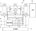
- power storage system 401 includes batteries BT1 and BT2, relays RY1 to RY7 and 28, onboard charger 20 as a power converter, and control circuit 45.
- An external charger is connected to the external charging connections 11 and 12 .
- AC power from an external commercial power supply is supplied to the AC power supply connectors 16 and 17 .
- Relays RY1-RY3 can switch the connection state of batteries BT1 and BT2 between series and parallel.
- the vehicle-mounted charger 20 transfers electric power between the batteries BT1 and BT2.
- the control circuit 45 controls the relays RY1 to RY7 and the vehicle charger 20.
- FIG. Before switching the batteries BT1 and BT2 to parallel connection, the control circuit 45 performs a voltage balancing process for operating the on-vehicle charger 20 so that the potential difference between the batteries BT1 and BT2 is equal to or less than a predetermined threshold.
- RY1 and RY3 are turned on.
- Relay 28 opens and closes paths between batteries BT1 and BT2 and onboard charger 20 .
- the load 80 is equipment commonly used in electric vehicles and plug-in hybrid vehicles, for example.
- a switching device includes a switching unit that switches connection states between nodes of N storage batteries connected in series and an output terminal of a charger, where N is an integer of 2 or more, and the switching unit , to switch the connection state according to the control signal.
- a switching device includes a switching unit that connects N storage batteries in series and switches a connection state between nodes of the N storage batteries that are connected in series and an output terminal of a charger, N is an integer equal to or greater than 2, and the switching unit switches the connection state according to the control signal.
- a power storage system includes the switching device described above and N storage batteries.
- FIG. 1 is a block diagram showing the configuration of a power storage system capable of charging two batteries by switching between series connection and parallel connection.
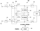
- FIG. 2 is a block diagram showing the configuration of the power storage system according to the embodiment of the present disclosure.
- FIG. 3 is a circuit diagram showing a configuration example of two storage batteries.
- FIG. 4 is a block diagram showing how two storage batteries are charged in the power storage system shown in FIG.
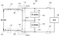
- FIG. 5 is a block diagram showing a state in which the first storage battery of the two storage batteries is charged in the power storage system shown in FIG. 6 is a block diagram showing a state in which the second storage battery of the two storage batteries is charged in the power storage system shown in FIG. 2.
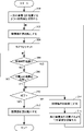
- FIG. FIG. 7 is a flow chart showing the process of switching the states shown in FIGS.
- FIG. 8 is a block diagram showing how power is supplied to a load from two storage batteries connected in series.
- FIG. 9 is a block diagram showing the configuration of the power storage system according to the first modified example.
- FIG. 10 is a block diagram showing the configuration of the power storage system according to the second modification.
- FIG. 11 is a block diagram showing the configuration of a power storage system according to the third modification.
- FIG. 12 is a block diagram showing the configuration of a power storage system in which a switch is made up of a plurality of switches.
- FIG. 13 is a block diagram showing the configuration of a power storage system including three storage batteries.
- the present disclosure provides a switching device and a power storage system that can charge a plurality of storage batteries by any of a plurality of chargers with different charging voltages without using a relay that switches between series connection and parallel connection of the plurality of storage batteries.
- a switching device and a power storage system that can charge a plurality of storage batteries by any of a plurality of chargers with different charging voltages without using a relay that switches between series connection and parallel connection of the plurality of storage batteries. can.
- a switching device includes a switching unit that switches connection states between nodes of N storage batteries connected in series and an output terminal of a charger, where N is an integer of 2 or more.
- the switching unit receives a control signal from the outside and switches the connection state. Accordingly, an appropriate storage battery can be connected to the charger according to the control signal without using a relay for switching between series connection and parallel connection of a plurality of storage batteries.
- a switching device connects N storage batteries in series, and switches the connection state between the nodes of the N storage batteries connected in series and the output terminal of the charger. section, where N is an integer of 2 or more, and the switching section receives a control signal from the outside and switches the connection state. Accordingly, an appropriate storage battery can be connected to the charger according to the control signal without using a relay for switching between series connection and parallel connection of a plurality of storage batteries.
- the N accumulators connected in series include a first accumulator and a second accumulator, the first accumulator and the second accumulator are interconnected by a common node, and the switching unit comprises: a first input terminal and a second input terminal to which electric power is input; a first output terminal connected to a common node; 2 output terminals and a third output terminal connected to a second node, which is a node different from the common node, of the second storage battery, and the switching unit is configured such that the control signal is the power of the first voltage from the charger.
- N is 2, and the switching unit alternates between the first mode and the second mode at a predetermined cycle when the control signal indicates that the power of the second voltage is supplied from the charger. to be realized.
- the first storage battery and the second storage battery can be maintained at substantially the same amount of charge during charging. Therefore, even when charging is interrupted and power is supplied from the first storage battery and the second storage battery, the storage amount of one of the first storage battery and the second storage battery does not become zero first, and the battery can be charged longer and longer. It can supply a lot of power.
- the switching device includes a first power path connecting the first output terminal and the common node, a second power path connecting the second output terminal and the first node, and a third output terminal. and a third power path connecting the and the second node.
- the switching unit includes a first switch for switching between a state in which the first input terminal is connected to the first output terminal and a state in which the first input terminal is connected to the second output terminal; A second switch for switching between a state in which the terminal is connected to the first output terminal and a state in which the second input terminal is connected to the third output terminal.
- the storage battery can be charged by both the high voltage (first voltage) output charger and the low voltage (second voltage) output charger.
- the first switch is composed of two two-contact switches, corresponding terminals of the two switches are both connected to the first input terminal, and the two switches are connected to the first input terminal.
- the two terminals other than the terminal connected to the first input terminal are connected to the first output terminal and the second output terminal in a one-to-one correspondence
- the second switch is a two-contact type switch. corresponding terminals of the two switches are both connected to the second input terminal, and two terminals of the two switches other than the terminal connected to the second input terminal are connected to the second output terminal and the third output terminal in a one-to-one correspondence.
- the first voltage is higher than both the nominal voltage of the first storage battery and the nominal voltage of the second storage battery.
- the first voltage is equal to the sum of the nominal voltage of the first storage battery and the nominal voltage of the second storage battery.
- the second voltage is equal to the nominal voltage of the first storage battery or the nominal voltage of the second storage battery.
- the N storage batteries connected in series include a first node and a second node located at both ends and a total of (N ⁇ 1) connection nodes located between two adjacent storage batteries.
- the switching unit includes a first input terminal and a second input terminal to which power from the charger is input, and the first input terminal is any one of the first node and (N ⁇ 1) connection nodes , and the second input terminal is connected to any one of the second node and (N ⁇ 1) connection nodes excluding the node to which the first input terminal is connected.
- a power storage system includes the switching device described above and N storage batteries. Accordingly, an appropriate storage battery can be connected to the charger according to the control signal without using a relay for switching between series connection and parallel connection of a plurality of storage batteries.
- the power storage system further includes a power converter that transfers power between any two of the N storage batteries.
- a power converter that transfers power between any two of the N storage batteries. This makes it possible to equalize the amounts of electricity stored in the plurality of storage batteries. Therefore, when power is supplied to the load from a plurality of storage batteries connected in series, it is possible to avoid a situation in which power cannot be supplied as a whole due to the power of only some of the storage batteries becoming zero.
- the power converter outputs power to two or more systems. Thereby, power can be supplied to a plurality of loads having different operating voltages.
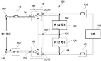
- the power storage system 100 includes a first storage battery 102, a second storage battery 104, a first switch 110, a second switch 112, a switching unit 114, and a third switch 120. , a fourth switch 122 and a controller 124 .
- the switching unit 114 includes a first switching device 116 and a second switching device 118, and constitutes a switching device.
- a load 106 is a target to which electric power is supplied from the first storage battery 102 and the second storage battery 104 .
- the output terminals of the charger are connected to the first terminal 140 and the second terminal 142 .
- the first storage battery 102 and the second storage battery 104 are connected in series, and the connection forms a first common node 130 .
- the first storage battery 102 and the second storage battery 104 are chargeable/dischargeable storage batteries (lithium ion batteries, etc.) having the same specifications.
- Each of the 1st storage battery 102 and the 2nd storage battery 104 is comprised by the storage battery.
- the term “storage battery” is used to include all of one storage battery cell, multiple storage battery cells, one storage battery module (a package of multiple storage battery cells), and multiple storage battery modules.
- the first storage battery 102 and the second storage battery 104 may be configured by dividing the plurality of storage battery cells 126 connected in series into the same number of halves, as shown in FIG.
- each of the first storage battery 102 and the second storage battery 104 is a storage battery configured by a plurality of storage battery cells.
- each of the first storage battery 102 and the second storage battery 104 has a specification of 400V (rated charging voltage and output voltage are 400V).
- the switching unit 114 includes input terminals IN1 and IN2 and output terminals OUT1, OUT2 and OUT3 in addition to the first switch 116 and the second switch 118 .
- the first switch 116 is connected to the input terminal IN1 and the output terminals OUT1 and OUT2. It switches between the state of being connected to OUT2.
- the second switch 118 is connected to the input terminal IN2 and the output terminals OUT1 and OUT3. It switches between the state of being connected to OUT3.
- the output terminal OUT1 is connected to the first common node 130 via the first power path 150 .
- the output terminal OUT2 is connected via a second power path 152 to a first node 132 other than the first common node 130 among the two nodes corresponding to both terminals of the first storage battery 102 .
- the output terminal OUT3 is connected via a third power path 154 to a second node 134 other than the first common node 130 among the two nodes corresponding to both terminals of the second storage battery 104 .
- the first power line 150, the second power line 152 and the third power line 154 are power lines.
- First power line 150, second power line 152 and third power line 154 may be configured in the form of wire harnesses.
- the switching unit 114 can switch between the state in which the input terminal IN1 is connected to the first common node 130 and the state in which the input terminal IN1 is connected to the first node 132 by the first switch 116 . Further, the switching unit 114 can switch between a state in which the input terminal IN2 is connected to the first common node 130 and a state in which the input terminal IN2 is connected to the second node 134 by the second switch 118 .
- the first switch 110, the second switch 112, the third switch 120, and the fourth switch 122 are, for example, relays. ) or open (hereinafter also referred to as off).
- Input terminal IN1 is connected to first terminal 140 via first switch 110 .
- Input terminal IN2 is connected to second terminal 142 via second switch 112 .
- Both terminals of the load 106 are connected to a first node 132 via a third switch 120 and to a second node 134 via a fourth switch 122, respectively.
- the first switch 110, the second switch 112, the third switch 120 and the fourth switch 122 may be mechanical relays or semiconductor relays.
- the power storage system 100 functions as a power supply unit in a mounted device.
- a charger is connected to the first terminal 140 and the second terminal 142 .
- the first switch 110 and the second switch 112 are turned on and the first switch 116 and the second switch 118 are appropriately switched, the electric power (charging direct current) supplied from the charger causes the first storage battery 102 to and the second storage battery 104 is charged.
- the first storage battery 102 and the second storage battery 104 can be charged by two types of chargers with different charging voltages. Rapid chargers for high-voltage charging of in-vehicle storage batteries include, for example, 400V chargers and 800V chargers.
- the first storage battery 102 and the second storage battery 104 can be charged by any charger.
- the power storage system 100 When the charger is not connected to the first terminal 140 and the second terminal 142, the power storage system 100 turns on the third switch 120 and the fourth switch 122 to charge the first storage battery 102 and the second storage battery. The discharge of 104 can power the load 106 .
- the control unit 124 controls on and off of the first switch 110, the second switch 112, the third switch 120, and the fourth switch 122, and switches the first switch 116 and the second switch 118. Control. During charging, the control unit 124 performs control to turn on the first switch 110 and the second switch 112, and performs the first switching according to charging information (information about the output voltage of the charger) input from the outside. 116 and the second switch 118 are switched.
- charging information is input from, for example, an ECU (Electronic Control Unit) that controls the operation of the vehicle.
- control unit 124 When power is supplied from the first storage battery 102 and the second storage battery 104 to the load 106 , the control unit 124 performs control to turn on the third switch 120 and the fourth switch 122 .
- the control unit 124 is implemented by a CPU (Central Processing Unit), a microcomputer (hereinafter referred to as a microcomputer), or the like.
- control unit 124 may be realized by an ECU that controls the operation of the vehicle.
- the first voltage is, for example, 800V. 4
- first switch 116 connects input terminal IN1 to output terminal OUT2
- second switch 118 connects input terminal IN2 to output. It will be in a state of being connected to the terminal OUT3. That is, the input terminals IN1 and IN2 are connected to the first node 132 and the second node 134, respectively.
- the third switch 120 and the fourth switch 122 are off.
- first switch 116 enters a state in which input terminal IN1 is connected to output terminal OUT2, and second switch 116 is connected to output terminal OUT2.
- 118 is in a state where the input terminal IN2 is connected to the output terminal OUT1. That is, the input terminals IN1 and IN2 are connected to the first node 132 and the first common node 130, respectively.
- the third switch 120 and the fourth switch 122 are off.
- the first switch 116 and the second switch 118 are switched to a state different from that in FIG. That is, referring to FIG. 6, under the control of control unit 124 (not shown in FIG. 6), first switch 116 enters a state in which input terminal IN1 is connected to output terminal OUT1, and the second The switch 118 enters a state in which the input terminal IN2 is connected to the output terminal OUT3. That is, the input terminals IN1 and IN2 are connected to the first common node 130 and the second node 134, respectively. At this time, the third switch 120 and the fourth switch 122 are off.
- control unit 124 The processing shown in FIG. 7 is executed by the control unit 124.
- the control unit 124 is a microcomputer having an internal memory.
- a predetermined program is stored in the internal memory of control unit 124, and the process of FIG. 7 is executed by reading out and executing the program.
- control unit 124 switches the first switch 116 and the second switch 118 so that one of the first storage battery 102 and the second storage battery 104 is charged.
- control unit 124 sets the first switch 116 and the second switch 118 as shown in FIG. are set as shown in FIG. Control then passes to step 302 .
- control unit 124 closes the charging switch. Specifically, the controller 124 turns on the first switch 110 and the second switch 112 . As a result, charging of either the first storage battery 102 or the second storage battery 104 is started. Control then passes to step 304 .
- control unit 124 resets the timer. It is assumed that the timer is realized by hardware or a program different from this program. The timer counts the elapsed time after resetting the counter to 0. Control then passes to step 306 .
- step 306 the control unit 124 determines whether or not a predetermined time T0 has elapsed since charging was started in step 302 (specifically, after resetting the timer).
- Predetermined time T0 is, for example, a value ranging from several seconds to several minutes, and is stored in the internal memory of control unit 124 in advance.
- Control unit 124 acquires the current elapsed time from the timer, and determines whether or not the predetermined time T0 read from the internal memory is equal to or longer than the predetermined time T0, thereby determining whether or not the predetermined time T0 has elapsed.
- control unit 124 determines that the predetermined time T0 has elapsed, and the control proceeds to step 310. Otherwise (elapsed time is less than predetermined time T0), control passes to step 308 .
- control unit 124 determines whether or not the storage battery that started charging at step 302 is fully charged. Specifically, control unit 124 determines whether or not the SOC of the storage battery that started charging in step 302 has reached a predetermined value (for example, 100%) or higher. The control unit 124 acquires the SOC, for example, from an ECU that monitors the states of the first storage battery 102 and the second storage battery 104 . If it is determined that the battery is fully charged, control proceeds to step 310 . Otherwise control returns to step 306 . As a result, steps 306 and 308 are repeated until either the predetermined time elapses or the storage battery whose charging is started in step 302 is fully charged, and the storage battery whose charging is started in step 302 is fully charged. Charge is maintained.
- a predetermined value for example, 100%
- control unit 124 determines whether or not to end. For example, when both the first storage battery 102 and the second storage battery 104 are fully charged, or when the operation device is operated to issue an end instruction, it is determined that charging is to be terminated. If so, control passes to step 312 . Otherwise control passes to step 314 .
- the controller 124 turns off (opens) the switch for charging. Specifically, the controller 124 turns off the first switch 110 and the second switch 112 . This stops the charging of the first storage battery 102 and the second storage battery 104 . After that, the program ends.
- step 314 the control unit 124 turns off (opens) the switch for charging. Specifically, the controller 124 turns off the first switch 110 and the second switch 112 . This stops the charging initiated by step 302 . Control then passes to step 316 .
- the first switch 116 and the second switch 118 are switched to charge a storage battery other than the storage battery for which charging was started at step 302. If the storage battery that started charging in step 302 is the first storage battery 102, the control unit 124 sets the first switch 116 and the second switch 118 as shown in FIG. Thereby, the second storage battery 104 becomes a charging target. If the storage battery that started charging in step 302 is the second storage battery 104, the control unit 124 sets the first switch 116 and the second switch 118 as shown in FIG. This makes the first storage battery 102 to be charged. Control then returns to step 302 . By executing step 302 again, charging of a storage battery different from the storage battery for which charging was started by executing step 302 last time starts.
- the charging of the first storage battery 102 and the charging of the second storage battery 104 are alternately repeated in a cycle of the predetermined time T0, charging is completed before both the first storage battery 102 and the second storage battery 104 are fully charged. Even if it is stopped, the amounts of electricity stored in the first storage battery 102 and the second storage battery 104 can be made substantially the same. Therefore, even when charging is interrupted and power is supplied from the first storage battery 102 and the second storage battery 104, the storage amount of one of the first storage battery 102 and the second storage battery 104 does not become zero first. Longer and more power can be delivered.
- the control unit 124 controls the third switch 120 and the fourth switch 122 is turned on. At this time, the first switch 110 and the second switch 112 are off, and the states of the first switch 116 and the second switch 118 are arbitrary. As a result, a current flows as indicated by dashed arrows in FIG. 8, and power is supplied to the load 106 from the first storage battery 102 and the second storage battery 104 that are connected in series.
- the load 106 is, for example, an inverter and a motor that drive a motor for running the vehicle. The inverter converts the electric power (direct current) supplied from the first storage battery 102 and the second storage battery 104 into alternating current and supplies the alternating current to the motor. As a result, the motor is driven (rotated) and the vehicle runs.
- the two series-connected accumulators include the first accumulator 102 and the second accumulator 104 .
- the first battery 102 and the second battery 104 are interconnected by a first common node 130 .
- a switching unit 114 constituting a switching device includes input terminals IN1 and IN2 to which electric power from a charger is input, an output terminal OUT1 connected to a first common node 130, and a first common node of the first storage battery 102.
- An output terminal OUT2 connected to a first node 132, which is a node different from 130, and an output terminal OUT3 connected to a second node 134, which is a node different from the first common node 130, of the second storage battery 104.
- the switching unit 114 When the control signal (charging information) indicates that power of the first voltage (for example, 800 V) is supplied from the charger, the switching unit 114 connects the input terminal IN1 to the output terminal OUT2 and connects the input terminal IN2. is connected to the output terminal OUT3.
- the control signal (charging information) indicates that the charger supplies power with a second voltage (eg, 400 V) lower than the first voltage (800 V)
- the switching unit 114 outputs the input terminal IN1.
- terminal OUT2 and input terminal IN2 is connected to output terminal OUT1, or input terminal IN1 is connected to output terminal OUT1 and input terminal IN2 is connected to output terminal OUT3.
- the first storage battery 102 and the second storage battery 104 can be charged by both the high voltage (first voltage) output charger and the low voltage (second voltage) output charger. Also, when power is supplied to the load 106 from the first storage battery 102 and the second storage battery 104, no current flows through the switching unit 114 (the first switching device 116 and the second switching device 118), so power loss can be reduced. .
- the switching device includes the first power path 150 connecting the output terminal OUT1 and the first common node 130, the second power path 152 connecting the output terminal OUT2 and the first node 132, and the output terminals A third power path 154 connecting OUT3 and the second node 134 may also be included.
- the switching unit 114 can be appropriately connected to the first storage battery 102 and the second storage battery 104 that are connected in series, increasing the degree of freedom in arrangement.
- power storage system 220 according to the first modification is obtained by adding power converter 222 to power storage system 100 shown in FIG. Therefore, the points different from power storage system 100 will be mainly described below without repeating redundant description.
- a first port 224 of the power converter 222 is connected to nodes corresponding to both terminals of the second storage battery 104 , that is, the first common node 130 and the second node 134 .
- a second port 226 of the power converter 222 is connected to nodes corresponding to both terminals of the first battery 102 , ie, a first node 132 and a first common node 130 .
- the power converter 222 is an isolated bidirectional DC/DC converter that generates a DC voltage of the same magnitude as the DC voltage input to the first port 224 and outputs it from the second port 226, A DC voltage having the same magnitude as the DC voltage input to 226 is generated and output from the first port 224 .
- the power converter 222 to mutually supply power between the first storage battery 102 and the second storage battery 104 .
- a current flows as indicated by the dashed line in FIG. 102 can be charged.
- the power of the first storage battery 102 is greater than the power of the second storage battery 104, the current flows in the direction opposite to the direction shown in FIG. 2 storage battery 104 can be charged.
- the power converter 222 includes, for example, a transformer and a bridge circuit composed of switching elements arranged on each of the primary side (input side) and secondary side (output side) of the transformer.
- the switching elements include, for example, FETs (Field Effect Transistors) or IGBTs (Insulated Gate Bipolar Transistors).
- a bridge circuit includes, for example, a full bridge circuit or a half bridge circuit.
- the control unit 124 turns on and off the switching elements constituting the bridge circuit with a control signal of a predetermined frequency, thereby converting the DC voltage input to the primary side of the transformer, generating a DC voltage, and generating a second voltage. Can be output from the next side. Since the primary side and the secondary side of the transformer included in the power converter 222 are insulated, the potential difference between both terminals of the first storage battery 102 and the potential difference between both terminals of the second storage battery 104 is also maintained at normal values.
- the control unit 124 acquires the SOCs of the first storage battery 102 and the second storage battery 104, If the SOC of the second storage battery 104 differs by a predetermined value or more, the power converter 222 is operated to make the SOCs of the first storage battery 102 and the second storage battery 104 equal to each other. supply power between As a result, for example, it is possible to avoid a situation in which the power storage amount of the first storage battery 102 becomes zero first and power cannot be supplied to the load 106 even though there is power remaining in the second storage battery 104 . More power can be supplied for a longer period of time than when power is not supplied from the first storage battery 102 .
- a power storage system 240 according to a second modification is obtained by adding a low-voltage load 204 and a multiport power converter 242 to the power storage system 100 shown in FIG.
- Power storage system 240 is also obtained by replacing power converter 222 with multiport power converter 242 in power storage system 220 shown in FIG. 9 and adding low-voltage load 204 . Therefore, without repeating redundant description, the points different from power storage system 100 and power storage system 220 will be mainly described below.
- the input port 244 of the multiport power converter 242 is connected to the nodes corresponding to both terminals of the second storage battery 104, that is, the first common node 130 and the second node 134.
- the output ports 246 of the multiport power converter 242 can output high and low DC voltages (eg, 400V and 12V).
- a terminal for outputting a high DC voltage (400 V) of the output port 246 is connected to both terminals of the high voltage load 202 .
- a terminal for outputting a low-voltage DC voltage (12 V) of the output port 246 is connected to both terminals of the low-voltage load 204 .
- the multiport power converter 242 includes, for example, a transformer having one primary coil (input side) and two secondary coils (output side), and a transformer primary coil (input side) and two secondary coils (output side). and a bridge circuit composed of switching elements connected to each of the two sides).
- the switching elements include FETs, IGBTs, or the like, for example.
- a bridge circuit includes, for example, a full bridge circuit or a half bridge circuit.
- the control unit 124 turns on and off the switching elements that constitute the bridge circuit with a control signal of a predetermined frequency, thereby converting the DC voltage input to the primary coil of the transformer to produce DC voltages of different magnitudes. can be generated and output from the two secondary coils.
- the power supplied from the second storage battery 104 to the input port 244 can be transmitted to the output port 246 and supplied to the first storage battery 102 and the low-voltage load 204.
- FIG. power can be supplied to the first storage battery 102 and the low-voltage load 204 having different operating voltages.
- the present invention is not limited to this.
- the first storage battery 102 and the second storage battery 104 may be connected in series inside the switching device.
- the power storage system according to the third modification has a function of connecting the first storage battery 102 and the second storage battery 104 in series inside the switching device.
- power storage system 260 replaces switching unit 114 with switching unit 262 in power storage system 100 shown in FIG. is added. Therefore, the points different from power storage system 100 will be mainly described below without repeating redundant description.
- the switching section 262 replaces the output terminal OUT1 with the output terminals OUT1a and OUT1b in the switching section 114 shown in FIG.
- the output terminals OUT1a and OUT1b are interconnected inside the switching section 262 .
- the terminal other than the first node 132 is connected to the output terminal OUT1a via the fourth power path 264 .
- the terminal other than the second node 134 is connected to the output terminal OUT1b via the fifth power path 266.
- the first storage battery 102 and the second storage battery 104 are connected in series inside the switching unit 262 .
- the first storage battery 102 and the second storage battery 104 can be charged as shown in FIGS. That is, both the high voltage (first voltage (800 V)) output charger and the low voltage (second voltage (400 V)) output charger can charge the first storage battery 102 and the second storage battery 104 . Also, when power is supplied to the load 106 from the first storage battery 102 and the second storage battery 104, as in FIG. Therefore, power loss can be reduced.
- the form which connects the 1st storage battery 102 and the 2nd storage battery 104 in series inside the switching part 262 is not limited to the form shown in FIG.
- FIG. 12 shows the configuration of a power storage system 270 in which each switch is configured using a two-contact type switch.
- the power storage system 270 shown in FIG. 12 replaces the first switching unit 116 and the second switching unit 118 in the power storage system 100 shown in FIG. 2 with a first switching unit 272 and a second switching unit 274, respectively.
- Electricity storage system 270 includes a control unit similar to electricity storage system 100, but is not shown in FIG.
- Each of the first switching section 272 and the second switching section 274 is composed of two two-contact switches.
- the two switches perform the same function as a three-terminal switch, with their corresponding ends connected together. Therefore, power storage system 270 functions similarly to power storage system 100 . If a two-contact switch that can be used in a high-voltage and high-current environment is adopted, the switching unit 114 that can be used in a high-voltage and high-current environment can be realized.
- FIG. 13 shows a configuration in which three storage batteries are connected in series.
- a power storage system 280 shown in FIG. 13 is obtained by adding a third storage battery 282 and a second common node 284 to the power storage system 270 shown in FIG.
- the switching unit 286 is obtained by replacing the first switching unit 272 and the second switching unit 274 in the switching unit 114 shown in FIG.
- the power storage system 280 includes a control unit like the power storage systems 100 and 270, but not shown in FIG.
- the third storage battery 282 has the same specification as the first storage battery 102 and the second storage battery 104 (for example, 400V specification).
- the output terminal OUT4 is connected to a second common node 284 formed by connecting the second storage battery 104 and the third storage battery 282 in series.
- Each of the third switching section 288 and the fourth switching section 290 is composed of three two-contact switches. Corresponding one ends of the three switches are commonly connected to form an input terminal. Each of the remaining three terminals that are not commonly connected are output terminals. With three batteries connected in series, there are four nodes.
- Each of the third switching section 288 and the fourth switching section 290 connects the corresponding input terminal to one of the three adjacent nodes among the four nodes. Specifically, the third switching section 288 is controlled by the control section to switch the input terminal IN1 to one of the three output terminals OUT2, OUT1 and OUT4, that is, the first node 132, the first common node 130 and the third switching section 288. 2 common node 284 .
- the fourth switching unit 290 is controlled by the control unit to switch the input terminal IN2 to one of the three output terminals OUT3, OUT4 and OUT1, that is, the second node 134, the second common node 284 and the first common node 130. Connect with either.
- the internal connection of the third switching section 288 and the fourth switching section 290 is such that the input terminal IN1 of the third switching section 288 and the input terminal IN2 of the fourth switching section 290 are connected to the output terminal of the third switching section 288 and the input terminal IN2 of the fourth switching section 290, respectively. 4 are controlled so as not to be connected via the output terminal of the switching section 290, that is, not to be connected to the same node at the same time.
- the input terminal IN1 of the third switching section 288 is connected to the output terminal OUT1 (first common node 130)
- the input terminal IN2 of the fourth switching section 290 is connected to the output terminal OUT4 (second common node 284).
- it is connected to the output terminal OUT3 (second node 134).
- the first storage battery 102 and the second storage battery can be charged in any of the mode of charging three storage batteries simultaneously, the mode of charging arbitrary two storage batteries simultaneously, and the mode of charging arbitrary one storage battery.
- 104 and the third storage battery 282 can be charged. That is, the power storage system 280 can handle three different charging voltages, for example, charging voltages of 1200V, 800V and 400V if each of the three storage batteries is rated at 400V.
- the power storage system 280 can handle three different charging voltages, for example, charging voltages of 1200V, 800V and 400V if each of the three storage batteries is rated at 400V.
- charging is preferably performed in the same manner as in FIG. That is, if the three modes of charging the first storage battery 102, charging the second storage battery, and charging the third storage battery 282 are repeated for a predetermined period of time T0 (a period during which each mode is maintained). can be charged evenly. Also, when two of the first storage battery 102, the second storage battery 104, and the third storage battery 282 are charged at 800 V, for example, it is preferable to charge them in the same manner as in FIG.
- three modes of charging the first storage battery 102 and the second storage battery 104, charging the second storage battery 104 and the third storage battery 282, and charging the third storage battery 282 and the first storage battery 102 are predetermined.
- T0 the period during which each form is maintained
- the batteries can be evenly charged. Therefore, even when charging is interrupted and electric power is supplied from the first storage battery 102, the second storage battery 104, and the third storage battery 282, one of the first storage battery 102, the second storage battery 104, and the third storage battery 282 can supply more power for a longer period of time without depleting the battery first.
- each process (each function) of the above-described embodiment can be realized by a processing circuit (Circuitry).
- each process of this embodiment can be realized by a processor that operates based on information such as a program and a storage device (memory) that stores information such as the program.
- the function of each unit may be implemented by separate hardware, or the function of each unit may be implemented by integrated hardware.
- a processor includes hardware, which may include circuitry for processing digital signals and/or circuitry for processing analog signals.
- the processor can be configured with one or more circuit devices (such as ICs) or one or more circuit elements (such as resistors, capacitors, etc.) mounted on a circuit board.
- a processor may be, for example, a CPU.
- the processor is not limited to the CPU, and various processors such as GPU (Graphics Processing Unit) or DSP (Digital Signal Processor) can be used.
- the processor may be a hardware circuit based on ASIC.
- the processor may be composed of a plurality of CPUs or a hardware circuit composed of a plurality of ASICs.
- the processor may be configured by a combination of multiple CPUs and multiple ASIC hardware circuits.
- the processor may also include amplifier circuits, filter circuits, or the like that process analog signals.
- the memory may be a semiconductor memory such as SRAM and DRAM, a register, a magnetic storage device such as a hard disk device, or an optical storage device such as an optical disk device.
Landscapes
- Engineering & Computer Science (AREA)
- Power Engineering (AREA)
- Charge And Discharge Circuits For Batteries Or The Like (AREA)
Priority Applications (2)
| Application Number | Priority Date | Filing Date | Title |
|---|---|---|---|
| JP2023534498A JPWO2023286185A1 (https=) | 2021-07-14 | 2021-07-14 | |
| PCT/JP2021/026391 WO2023286185A1 (ja) | 2021-07-14 | 2021-07-14 | 切替装置及び蓄電システム |
Applications Claiming Priority (1)
| Application Number | Priority Date | Filing Date | Title |
|---|---|---|---|
| PCT/JP2021/026391 WO2023286185A1 (ja) | 2021-07-14 | 2021-07-14 | 切替装置及び蓄電システム |
Publications (1)
| Publication Number | Publication Date |
|---|---|
| WO2023286185A1 true WO2023286185A1 (ja) | 2023-01-19 |
Family
ID=84919733
Family Applications (1)
| Application Number | Title | Priority Date | Filing Date |
|---|---|---|---|
| PCT/JP2021/026391 Ceased WO2023286185A1 (ja) | 2021-07-14 | 2021-07-14 | 切替装置及び蓄電システム |
Country Status (2)
| Country | Link |
|---|---|
| JP (1) | JPWO2023286185A1 (https=) |
| WO (1) | WO2023286185A1 (https=) |
Cited By (1)
| Publication number | Priority date | Publication date | Assignee | Title |
|---|---|---|---|---|
| WO2026079060A1 (ja) * | 2024-10-10 | 2026-04-16 | 株式会社デンソー | 電力供給システム、電力供給プログラム、及び電力供給方法 |
Citations (2)
| Publication number | Priority date | Publication date | Assignee | Title |
|---|---|---|---|---|
| JP2009296820A (ja) * | 2008-06-06 | 2009-12-17 | Toyota Motor Corp | 二次電池の充電制御装置および充電制御方法ならびに電動車両 |
| JP2019080473A (ja) * | 2017-10-27 | 2019-05-23 | 株式会社デンソー | 蓄電システム |
Family Cites Families (3)
| Publication number | Priority date | Publication date | Assignee | Title |
|---|---|---|---|---|
| JP2000324709A (ja) * | 1999-05-06 | 2000-11-24 | Matsushita Electric Ind Co Ltd | 充電装置 |
| JP2014057398A (ja) * | 2012-09-11 | 2014-03-27 | Panasonic Corp | 蓄電池管理装置および蓄電池管理方法 |
| DE102015106771A1 (de) * | 2015-04-30 | 2016-11-03 | Dr. Ing. H.C. F. Porsche Aktiengesellschaft | Batteriesystem |
-
2021
- 2021-07-14 WO PCT/JP2021/026391 patent/WO2023286185A1/ja not_active Ceased
- 2021-07-14 JP JP2023534498A patent/JPWO2023286185A1/ja active Pending
Patent Citations (2)
| Publication number | Priority date | Publication date | Assignee | Title |
|---|---|---|---|---|
| JP2009296820A (ja) * | 2008-06-06 | 2009-12-17 | Toyota Motor Corp | 二次電池の充電制御装置および充電制御方法ならびに電動車両 |
| JP2019080473A (ja) * | 2017-10-27 | 2019-05-23 | 株式会社デンソー | 蓄電システム |
Cited By (1)
| Publication number | Priority date | Publication date | Assignee | Title |
|---|---|---|---|---|
| WO2026079060A1 (ja) * | 2024-10-10 | 2026-04-16 | 株式会社デンソー | 電力供給システム、電力供給プログラム、及び電力供給方法 |
Also Published As
| Publication number | Publication date |
|---|---|
| JPWO2023286185A1 (https=) | 2023-01-19 |
Similar Documents
| Publication | Publication Date | Title |
|---|---|---|
| CN111264014B (zh) | 蓄电系统 | |
| US20200055404A1 (en) | Vehicle and electrical system with dual battery modules | |
| US20130181680A1 (en) | Fault tolerant modular battery management system | |
| CN110249475A (zh) | 电池模块均衡装置以及包括其的电池组和车辆 | |
| US12275329B2 (en) | Multi-voltage storage system for an at least partially electrically driven vehicle | |
| JP5744598B2 (ja) | バランス補正装置および蓄電システム | |
| CN105703434A (zh) | 一种具有主动均衡功能的电池管理系统 | |
| IT201900001099A1 (it) | Gruppo e metodo di ricarica e alimentazione per un veicolo elettrico, e veicolo elettrico comprendente il gruppo di ricarica e alimentazione | |
| CN209298226U (zh) | 电池组件和电子设备 | |
| CN115320377A (zh) | 用于车辆的电力系统 | |
| CN117543740A (zh) | 蓄电系统 | |
| US10498145B2 (en) | Balancing of a battery having two branches, with bridging of differential numbers of storage elements | |
| JP2013223378A (ja) | 電池均等化システムおよび方法 | |
| WO2023286185A1 (ja) | 切替装置及び蓄電システム | |
| JP2018098954A (ja) | 電動車両の制御装置 | |
| JP7309275B2 (ja) | 電池システム | |
| WO2024068257A1 (en) | Battery unit, method and apparatus for operating the battery unit | |
| CN117584812A (zh) | 具有电荷平衡电路的双牵引电池电力系统 | |
| CN114475287A (zh) | 用于为电动车辆的电池充电的充电系统和方法 | |
| CN205544439U (zh) | 一种具有主动均衡功能的电池管理系统 | |
| CN114788120A (zh) | 车载电池系统 | |
| EP4312343B1 (en) | Balancing, precharge & active discharge operation of split hv battery systems in electric vehicles | |
| JP7666602B2 (ja) | 充電装置 | |
| JP7559298B2 (ja) | バッテリー装置、バッテリー管理システムおよび診断方法 | |
| CN115703376A (zh) | 充电系统、电池系统和用于运行电池系统的方法 |
Legal Events
| Date | Code | Title | Description |
|---|---|---|---|
| 121 | Ep: the epo has been informed by wipo that ep was designated in this application |
Ref document number: 21950126 Country of ref document: EP Kind code of ref document: A1 |
|
| WWE | Wipo information: entry into national phase |
Ref document number: 2023534498 Country of ref document: JP |
|
| NENP | Non-entry into the national phase |
Ref country code: DE |
|
| 122 | Ep: pct application non-entry in european phase |
Ref document number: 21950126 Country of ref document: EP Kind code of ref document: A1 |