WO2023286184A1 - 充電装置 - Google Patents
充電装置 Download PDFInfo
- Publication number
- WO2023286184A1 WO2023286184A1 PCT/JP2021/026390 JP2021026390W WO2023286184A1 WO 2023286184 A1 WO2023286184 A1 WO 2023286184A1 JP 2021026390 W JP2021026390 W JP 2021026390W WO 2023286184 A1 WO2023286184 A1 WO 2023286184A1
- Authority
- WO
- WIPO (PCT)
- Prior art keywords
- power
- storage battery
- node
- charger
- output
- Prior art date
- Legal status (The legal status is an assumption and is not a legal conclusion. Google has not performed a legal analysis and makes no representation as to the accuracy of the status listed.)
- Ceased
Links
Images


Classifications
-
- H—ELECTRICITY
- H02—GENERATION; CONVERSION OR DISTRIBUTION OF ELECTRIC POWER
- H02J—ELECTRIC POWER NETWORKS; CIRCUIT ARRANGEMENTS OR SYSTEMS FOR SUPPLYING OR DISTRIBUTING ELECTRIC POWER; SYSTEMS FOR STORING ELECTRIC ENERGY
- H02J7/00—Circuit arrangements for charging or discharging batteries or for supplying loads from batteries
- H02J7/02—Circuit arrangements for charging or discharging batteries or for supplying loads from batteries for charging batteries from AC mains by converters
-
- Y—GENERAL TAGGING OF NEW TECHNOLOGICAL DEVELOPMENTS; GENERAL TAGGING OF CROSS-SECTIONAL TECHNOLOGIES SPANNING OVER SEVERAL SECTIONS OF THE IPC; TECHNICAL SUBJECTS COVERED BY FORMER USPC CROSS-REFERENCE ART COLLECTIONS [XRACs] AND DIGESTS
- Y02—TECHNOLOGIES OR APPLICATIONS FOR MITIGATION OR ADAPTATION AGAINST CLIMATE CHANGE
- Y02T—CLIMATE CHANGE MITIGATION TECHNOLOGIES RELATED TO TRANSPORTATION
- Y02T10/00—Road transport of goods or passengers
- Y02T10/60—Other road transportation technologies with climate change mitigation effect
- Y02T10/70—Energy storage systems for electromobility, e.g. batteries
Definitions
- the present disclosure relates to a charging device.
- a secondary battery (storage battery) installed in a plug-in hybrid vehicle (hereinafter referred to as a PHEV (Plug-in Hybrid Electric Vehicle)) or an electric vehicle (hereinafter referred to as an EV (Electric Vehicle)) is an external power supply (external charger).
- PHEV Plug-in Hybrid Electric Vehicle
- EV Electric Vehicle
- in-vehicle storage batteries have become more compatible with high voltages, and chargers with a higher voltage (e.g., 800 V) than current mainstream chargers (e.g., chargers with a charging voltage of 400 V (hereinafter referred to as 400 V chargers)) (hereinafter referred to as There is a movement to promote 800V chargers. In the transitional period, it is expected that chargers with multiple charging voltages (400V and 800V) will coexist in the market.
- Patent Document 1 discloses a power storage system that can switch between series connection and parallel connection of a plurality of batteries.
- This power storage system can balance the voltages of a plurality of batteries while avoiding loss and shortening of contact life when switching from series connection to parallel connection of the plurality of batteries.
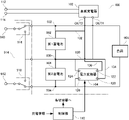
- power storage system 401 includes batteries BT1 and BT2, relays RY1 to RY7 and 28, onboard charger 20 as a power converter, and control circuit 45.
- An external charger is connected to the external charging connections 11 and 12 .
- AC power from an external commercial power supply is supplied to the AC power supply connectors 16 and 17 .
- Relays RY1-RY3 can switch the connection state of batteries BT1 and BT2 between series and parallel.
- the input/output port P1 of the in-vehicle charger 20 is connected to the positive and negative terminals of the battery BT1, and the input/output port P2 is connected to the positive and negative terminals of the battery BT2.
- the vehicle-mounted charger 20 converts AC power supplied from the commercial power supply to the AC power supply connectors 16 and 17 into DC power to charge the batteries BT1 and BT2. Also, the vehicle-mounted charger 20 transfers electric power between the batteries BT1 and BT2.
- the control circuit 45 controls the relays RY1 to RY7 and the vehicle charger 20.
- the control circuit 45 Before switching the batteries BT1 and BT2 to parallel connection, the control circuit 45 performs a voltage balancing process for operating the on-vehicle charger 20 so that the potential difference between the batteries BT1 and BT2 is equal to or less than a predetermined threshold.
- RY1 and RY3 are turned on.
- Relay 28 opens and closes paths between batteries BT1 and BT2 and onboard charger 20 .
- the load 80 is equipment commonly used in electric vehicles and plug-in hybrid vehicles, for example.
- a charging device includes: a power path that supplies power output from an onboard charger to M cells for a first storage battery among N storage battery cells connected in series; a power converter that converts the power output from the charger, N is an integer of 2 or more, M is an integer of 1 or more, and the power converter converts the converted power to the N storage batteries supply to M cells for the second storage battery among the cells for storage.
- FIG. 1 is a block diagram showing the configuration of a power storage system capable of charging two batteries by switching between series connection and parallel connection.
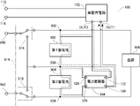
- FIG. 2 is a block diagram showing the configuration of the power storage system according to the embodiment of the present disclosure.
- FIG. 3 is a circuit diagram showing a configuration example of two storage batteries.
- FIG. 4 is a block diagram showing a state in which two storage batteries are charged by an onboard charger in the power storage system shown in FIG.
- FIG. 5 is a block diagram showing a configuration for supplying electric power from the second storage battery to the first storage battery.
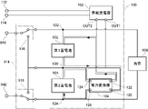
- FIG. 6 is a block diagram showing the configuration of the power storage system according to the first modified example.
- FIG. 7 is a block diagram showing the configuration of a power storage system according to a second modification.
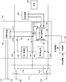
- FIG. 8 is a block diagram showing the configuration of a power storage system according to a third modification.
- an object of the present disclosure is to provide a charging device capable of charging a plurality of series-connected storage batteries with an on-vehicle charger that outputs a charging voltage lower than the series voltage.
- a charging device supplies electric power output from an onboard charger to M cells for a first storage battery among N storage battery cells connected in series.
- a power path and a power converter that converts the power output from the onboard charger N is an integer of 2 or more
- M is an integer of 1 or more
- the power converter converts the power after conversion.
- M cells for the second storage battery among the N storage battery cells M cells for the second storage battery among the N storage battery cells.
- the first accumulator and the second accumulator are interconnected by a common node, and the power path connects a first terminal of the two output terminals of the on-board charger to the common node. and a second power line connecting a second terminal of the two output terminals of the onboard charger to a first node, which is a node different from the common node among the nodes of the first storage battery and the second storage battery.
- the third terminal of the two output terminals of the power converter is connected to a common node
- the fourth terminal of the two output terminals of the power converter is connected to the common node of the nodes of the first storage battery and the second storage battery. and a second node that is different from the first node.
- the vehicle-mounted charger can be appropriately connected to the series-connected M cells for the first storage battery and M cells for the second storage battery, increasing the degree of freedom in arrangement.
- the charging device further includes N storage battery cells connected in series and an onboard charger.
- the series-connected M cells for the first storage battery and the M cells for the second storage battery can be charged by the vehicle-mounted charger with a charging voltage lower than the series voltage.
- the charging device exchanges power between the first storage battery and the second storage battery via the power converter. This makes it possible to equalize the amounts of electricity stored in the plurality of storage batteries. Therefore, when power is supplied to the load from a plurality of storage batteries connected in series, it is possible to avoid a situation in which power cannot be supplied as a whole due to the power of only some of the storage batteries becoming zero.
- the power converter is a multiport power converter that outputs power to two or more systems. Thereby, power can be supplied to a plurality of loads having different voltage specifications.
- the power storage system 100 includes an onboard charger 102, a power converter 104, power paths 130, 132, 134 and 136, a first storage battery 902, a second A storage battery 904 is included.
- the power storage system 100 can be mounted in a vehicle such as a PHEV or EV, for example.
- Terminals 112 and 114 are connected to the input portion of the vehicle-mounted charger 102, and by connecting a commercial power supply to the terminals 112 and 114, the first storage battery 902 and the second storage battery 904 are charged as described later. .
- AC charging charging with AC power from a commercial power supply will be referred to as AC charging.
- a charging device for AC charging the first storage battery 902 and the second storage battery 904 is composed of the components of the power storage system 100 excluding the first storage battery 902 , the second storage battery 904 , and the vehicle-mounted charger 102 .
- the first storage battery 902 and the second storage battery 904 are connected in series, and the connection forms a first common node 930 .
- the first storage battery 902 and the second storage battery 904 are chargeable/dischargeable storage batteries (lithium ion batteries, etc.) having the same specifications.
- Each of the first storage battery 902 and the second storage battery 904 is configured by a storage battery.
- the term “battery” is used to include all of one storage battery cell, multiple storage battery cells, one storage battery module (package of multiple storage battery cells), and multiple storage battery modules. . For example, as shown in FIG.
- the first storage battery 902 and the second storage battery 904 each have N (N is an integer of 2 or more) connected in series with the same number of storage battery cells 140 (M (M is 1 or more)). integer))).
- N is an integer of 2 or more
- M is 1 or more
- integer integer
- a first common node 930 is provided in an 800V battery module 142 .
- a plurality of storage battery cells between node 932 and first common node 930 are cells for first storage battery 902 (ie, cells functioning as first storage battery 902).
- a plurality of storage battery cells between first common node 930 and node 934 are cells for second storage battery 904 (ie, cells functioning as second storage battery 904).
- each of the first storage battery 902 and the second storage battery 904 has a specification of 400V (rated charging voltage and output voltage are 400V).
- Each node has the same potential as the corresponding terminal of the terminals (positive terminal and negative terminal) of the first storage battery 902 and the second storage battery 904. means connection to the terminal of
- FIG. 2 shows a switching unit 914 (switches 916 and 918) and terminals 940 and 942 required for charging the first storage battery 902 and the second storage battery 904 by the external charger.
- the first storage battery 902 and the second storage battery 904 are charged by connecting the output terminals of the external charger to terminals 940 and 942, respectively.
- FIG. 2 also shows a load 906 to which electric power is supplied from the first storage battery 902 and the second storage battery 904 .
- the in-vehicle charger 102 is an AC/DC converter that converts AC power input from terminals 112 and 114 into DC power and outputs the DC power.
- AC power (for example, 100 V or 200 V) is supplied to the vehicle-mounted charger 102 from a commercial power supply. Specifically, a connector of a connection cable connected to a commercial power source is attached to a socket including terminals 112 and 114 , and AC power is input to terminals 112 and 114 .
- the vehicle-mounted charger 102 is controlled by, for example, an ECU (Electronic Control Unit) (not shown) to generate and output DC power from input AC power.
- ECU Electronic Control Unit
- each of the first storage battery 902 and the second storage battery 904 has a 400V specification, so the output voltage of the vehicle charger 102 is 400V.
- the output terminal OUT1 of the vehicle-mounted charger 102 is connected to the first common node 930 via the power line 130 .
- the power line 130 means a power line connecting the output terminal OUT1 and the first common node 930 .
- Output terminal OUT2 of onboard charger 102 is connected to node 932 via power path 132 .
- the power line 132 means a power line connecting the output terminal OUT2 and the node 932 .
- the power converter 104 is an isolated DC/DC converter and includes a transformer (not shown).
- Power converter 104 includes terminals 120 , 122 , 124 and 126 .
- the power converter 104 includes, for example, a bridge circuit composed of switching elements between the terminals 120 and 122 and the primary coil of the transformer and between the terminals 124 and 126 and the secondary coil of the transformer.
- a FET Field Effect Transistor
- IGBT Insulated Gate Bipolar Transistor
- Power converter 104 generates DC power from the DC power input to terminals 120 and 122 under the control of control unit 110 and outputs the DC power from terminals 124 and 126 .
- the output voltage of power converter 104 is the same magnitude as the input voltage to power converter 104 . Since the output voltage of the onboard charger 102 is 400V, the input and output voltages of the power converter 104 are 400V.
- the terminal 120 is connected to the output terminal OUT1 of the onboard charger 102 via a power line 134 (the power line 134 is connected to the power line 130).
- the power line 134 means a power line connecting the output terminal OUT ⁇ b>1 and the terminal 120 .
- Terminal 122 is connected to output terminal OUT2 of onboard charger 102 via power path 136 (power path 136 is connected to power path 132).
- a power line 136 means a power line that connects the output terminal OUT2 and the terminal 122 .
- Terminal 124 is connected to power path 130 and is also connected to first common node 930 .
- Terminal 126 is connected to node 934 .
- the charging information input to the control unit 110 may include information regarding the voltage of rapid charging and information regarding AC charging. If the charging information includes information instructing execution of AC charging, control unit 110 controls the power conversion operation of power converter 104 . Specifically, the control unit 110 controls on and off of the switching elements included in the power converter 104, so that the power converter 104 outputs a voltage having the same magnitude as the input voltage as described above. It functions as a DC/DC converter. It should be noted that control unit 110 controls switching of switches 916 and 918 according to charging information during rapid charging. Switch 916 switches between a state in which terminal 940 is connected to node 932 and a state in which terminal 940 is connected to first common node 930 under the control of control unit 110 . Switch 918 switches between a state in which terminal 942 is connected to first common node 930 and a state in which terminal 942 is connected to node 934 under the control of control unit 110 .
- AC charging operation In AC charging, when the vehicle charger 102 outputs a DC voltage (400 V) from the output terminals OUT1 and OUT2 under the control of the ECU, the output voltage of the vehicle charger 102 is between the first common node 930 and the node 932. supplied to Thereby, the first storage battery 902 is charged. Also, the output voltage of onboard charger 102 is converted by power converter 104 and provided between first common node 930 and node 934 . Thereby, the second storage battery 904 is charged. The charging current at this time is indicated by a dashed arrow in FIG. In this manner, in the power storage system 100, the first storage battery 902 and the second storage battery 904 that are connected in series can be simultaneously charged with the electric power output from the vehicle-mounted charger 102. FIG.
- first storage battery 902 and the second storage battery 904 are of the same type (for example, the same product number), due to variations in individual characteristics, when AC charging is performed as described above, the first storage battery 902 and the second storage battery 904 An imbalance may occur in the amount of electricity stored in the second storage battery 904 .
- the amount of power stored in the first storage battery 902 is lower than the amount of power stored in the second storage battery 904 .
- the power converter 104 may be a bidirectional DC/DC converter.
- power converter 104 is an insulated DC/DC converter, receives control of control unit 110, generates DC power from DC power input to terminals 120 and 122, and generates DC power from terminal 124. and output from 126 . Further, the power converter 104 is controlled by the control unit 110 to generate DC power from the DC power input to the terminals 124 and 126 (output power of the second storage battery 904) and output from the terminals 120 and 122. . As a result, a current flows as indicated by the dashed line in FIG. 5, and the power of the second storage battery 904 can be transferred to the first storage battery 902 to charge the first storage battery 902 . Since the power converter 104 is an isolated DC/DC converter, the potential difference between both terminals of the first storage battery 902 and the potential difference between both terminals of the second storage battery 904 are both maintained at normal values. .
- the control unit 110 sets SOC (State Of Charge) representing the charging rate (%) of the first storage battery 902 and the second storage battery 904. to get If the absolute value (difference) of the value obtained by subtracting the SOC of the first storage battery 902 from the SOC of the second storage battery 904 is greater than or equal to a predetermined value, the control unit 110 controls the control unit 110 so that the difference is less than the predetermined value.
- Power converter 104 is operated to supply power from the storage battery with the higher SOC to the storage battery with the lower SOC.
- the charging device includes power paths 130 and 132 that supply power output from the vehicle charger 102 to the first storage battery 902 of the two storage batteries connected in series, and and a power converter 104 that converts DC power.
- the power converter 104 supplies the converted power to the second one of the two storage batteries 904 .
- the series-connected first storage battery 902 and second storage battery 904 can be charged by an onboard charger that outputs a charging voltage (eg, 400 V) lower than the series voltage (eg, 800 V).
- the power converter 104 is an isolated DC/DC converter.
- the voltage (eg, 400 V) of the power converted by the power converter 104 is the same as the voltage (eg, 400 V) of the power output from the onboard charger.
- the first storage battery 902 and the second storage battery 904 connected in series can be charged simultaneously.
- the power paths include a first power path (power path 130) connecting a first terminal (output terminal OUT1) of two output terminals OUT1 and OUT2 of onboard charger 102 to a common node.
- the power path connects the second terminal (output terminal OUT2) of the two output terminals of the vehicle-mounted charger 102 to the second terminal (output terminal OUT2) of the nodes of the first storage battery 902 and the second storage battery 904, which is a node different from the common node.
- a second power path (power path 132) that connects to one node (node 932).
- the third terminal (terminal 124) of the two output terminals of power converter 104 is connected to a common node (first common node 930).
- a fourth terminal (terminal 126) of the two output terminals of the power converter 104 is a common node among the nodes of the first storage battery 902 and the second storage battery 904, and a second node (a node different from the first node). node 934).
- the charging device may further include a first switch arranged on the power path 130 and a second switch arranged on the power path 132 .
- the first switch and the second switch switch between an open state (OFF) and a closed state (ON) under the control of the control unit 110 .
- the first switch and the second switch may be mechanical relays or semiconductor relays.
- the first switch and the second switch are closed when the first storage battery 902 and the second storage battery 904 are charged by the on-vehicle charger 102, and the first storage battery 902 and the second storage battery 904 are connected to the external charger. , it is open.
- the onboard charger 102 can be protected when the first storage battery 902 and the second storage battery 904 are charged by the external charger.
- the first storage battery 902 is directly charged with the output power of the vehicle charger 102 and the second storage battery 904 is charged via the power converter 104 during AC charging in the power storage system 100 (see FIG. 2). Illustrated, but not limited to.
- the second storage battery 904 may be directly charged with the output power of the vehicle-mounted charger 102
- the first storage battery 902 may be charged via the power converter 104 .
- the power storage system 150 is the power storage system 100 shown in FIG.
- constituent elements assigned the same reference numerals as in FIG. 2 have the same functions as in FIG. Therefore, without repeating the redundant description, the points of difference between power storage system 150 and power storage system 100 will be mainly described below.
- the output terminal OUT ⁇ b>1 of the onboard charger 102 is connected to the node 934 via the power line 152 .
- Output terminal OUT2 of on-board charger 102 is connected to first common node 930 via power path 130 . That is, the power line 130 means a power line connecting the output terminal OUT1 and the first common node 930, and the power line 152 means a power line connecting the output terminal OUT2 and the node 934.
- FIG. Terminal 124 of onboard charger 102 is connected to node 932 of first battery 902 and terminal 126 is connected to first common node 930 .
- Terminals 120 and 122 of power converter 104 are connected to output terminals OUT2 and OUT1 of on-board charger 102 via power paths 134 and 136, respectively. That is, the power line 134 means a power line connecting the output terminal OUT1 and the terminal 120, and the power line 136 means a power line connecting the output terminal OUT2 and the terminal 122.
- FIG. 1 the power line 134 means a power line connecting the output terminal OUT1 and the terminal 120
- the power line 136 means a power line connecting the output terminal OUT2 and the terminal 122.
- the vehicle charger 102 In AC charging, when the vehicle charger 102 outputs a DC voltage (400 V) from the output terminals OUT1 and OUT2 under the control of the ECU, the output voltage of the vehicle charger 102 is between the first common node 930 and the node 934. supplied to Thereby, the second storage battery 904 is charged. Also, the output voltage of onboard charger 102 is converted by power converter 104 and provided between first common node 930 and node 932 . Thereby, the first storage battery 902 is charged. In this manner, in the power storage system 150 , the first storage battery 902 and the second storage battery 904 connected in series can be simultaneously charged with the electric power output from the vehicle-mounted charger 102 .
- a DC voltage 400 V
- the first storage battery 902 and the second storage battery 904 are interconnected by a common node (first common node 930).
- the power paths include a first power path (power path 130) that connects a first terminal (output terminal OUT2) of two output terminals OUT1 and OUT2 of onboard charger 102 to a common node.
- the power path connects the second terminal (output terminal OUT1) of the two output terminals of the vehicle-mounted charger 102 to the second terminal (output terminal OUT1) of the nodes of the first storage battery 902 and the second storage battery 904, which is a node different from the common node.
- the third terminal (terminal 126) of the two output terminals of power converter 104 is connected to a common node (first common node 930).
- a fourth terminal (terminal 124) of the two output terminals of the power converter 104 is a common node among the nodes of the first storage battery 902 and the second storage battery 904, and a second node (the second node) which is a node different from the first node. node 932).
- power storage system 160 is power storage system 100 shown in FIG. and the control unit 110 are replaced by a switching unit 170 and a control unit 180, respectively.
- Switching section 170 is obtained by adding switches 172 and 174 to switching section 914 (FIG. 2).
- the third storage battery 162 has the same specification as the first storage battery 902 and the second storage battery 904 (for example, 400V specification).
- the switch 172 is connected to a first common node 930 formed by connecting the first storage battery 902 and the second storage battery 904 in series.
- the switching unit 174 is connected to a second common node 164 formed by connecting the second storage battery 904 and the third storage battery 162 in series.
- constituent elements assigned the same reference numerals as in FIG. 2 have the same functions as in FIG. Therefore, without repeating the redundant description, mainly the differences between power storage system 160 and power storage system 100 will be described below.
- the input part of the power converter 104 is connected to the output terminals OUT1 and OUT2 of the on-board charger 102 via power paths 134 and 136, as in the power storage system 100 .
- the output of power converter 104 is connected to first common node 930 and second common node 164 unlike power storage system 100 .
- the power converter 166 is an insulated DC/DC converter like the power converter 104, and includes a transformer and a bridge circuit composed of switching elements.
- the input of power converter 166 is connected to output terminals OUT1 and OUT2 of onboard charger 102 via power paths 134 and 136 .
- the output of power converter 166 is connected to second common node 164 and node 934 .
- Power converter 166 is controlled by control unit 180 to generate and output DC power from the DC power input from vehicle-mounted charger 102 .
- the output voltage of power converter 166 is the same magnitude as the input voltage of power converter 166 . Since the output voltage of the onboard charger 102 is 400V, the input and output voltages of the power converter 166 are 400V.
- control unit 180 receives charging information, controls each switch, and controls the power converter 104 .
- Control unit 180 also controls power converter 166 . That is, the control unit 180 controls on and off of the switching elements included in the power converter 166, so that the power converter 166 outputs a voltage having the same magnitude as the input voltage as described above. Acts as a converter.
- the output power of the onboard charger 102 is between the first common node 930 and the node 932. , which charges the first storage battery 902 .
- the output voltage of on-board charger 102 is converted by power converter 104 and provided between first common node 930 and second common node 164 .
- the second storage battery 904 is charged.
- the output voltage of onboard charger 102 is converted by power converter 166 and provided between second common node 164 and node 934 .
- the third storage battery 162 is charged.
- the charging current at this time is indicated by a dashed arrow in FIG.
- the first storage battery 902 , the second storage battery 904 and the third storage battery 162 connected in series can be charged simultaneously with the electric power output from the vehicle-mounted charger 102 .
- each of the power converter 104 and the power converter 166 is a bidirectional DC/DC converter, any two of the first storage battery 902, the second storage battery 904 and the third storage battery 162 Electricity can be supplied between two storage batteries to equalize the amount of stored electricity.
- the potential difference between both terminals of the first storage battery 902, the potential difference between both terminals of the second storage battery 904, and The potential difference between both terminals of the third storage battery 162 is maintained at a normal value. Therefore, when power is supplied to the load from a plurality of storage batteries connected in series, it is possible to avoid a situation in which power cannot be supplied as a whole due to the power of only some of the storage batteries becoming zero.
- the present invention is not limited to this.
- the power converter has a plurality of output units.
- power storage system 190 replaces power converter 104 and control unit 110 in power storage system 100 shown in FIG. 2 with multiport power converter 192 and control unit 198, respectively. However, it is modified so that power can be supplied from the second storage battery 904 to the first storage battery 902 and the low-voltage auxiliary machine 204 via the multiport power converter 192 .
- constituent elements assigned the same reference numerals as in FIG. 2 have the same functions as in FIG. Therefore, the points different from power storage system 100 will be mainly described below without repeating redundant description.
- the input port 194 of the multiport power converter 192 is connected to nodes corresponding to both terminals of the second storage battery 904 . That is, input port 194 is connected to node 934 and first common node 930 .
- the output ports 196 of the multiport power converter 192 can output high and low DC voltages (eg, 400V and 12V).
- a terminal for outputting a high DC voltage (400 V) of the output port 196 is connected to both terminals (a first common node 930 and a node 932) of the first storage battery 902 via the power paths 134 and 136. .
- a terminal for outputting a low-voltage DC voltage (12 V) of the output port 196 is connected to both terminals of the low-voltage auxiliary machine 204 .
- the low-voltage auxiliary machine 204 is accessory equipment necessary for operating the vehicle engine, motor, etc., and mainly includes a starter motor, an alternator, a radiator cooling fan, and the like.
- Low voltage accessories 204 may include lighting, wiper drives, navigation devices, air conditioners, heaters, and the like.
- the multiport power converter 192 is connected to, for example, a transformer having one primary coil (input side) and two secondary coils (output side), and each of the primary coil and the two secondary coils of the transformer. and a bridge circuit composed of switching elements.
- the switching elements include FETs, IGBTs, or the like, for example.
- a bridge circuit includes, for example, a full bridge circuit or a half bridge circuit.
- the control unit 198 turns on and off the switching elements that form the bridge circuit with a control signal of a predetermined frequency, thereby converting the DC voltage input to the primary coil of the transformer into different DC voltages. A voltage can be generated and output from the two secondary coils.
- the electric power supplied from the second storage battery 904 to the input port 194 is transmitted to the output port 196 and supplied to the first storage battery 902 and the low-voltage auxiliary machine 204. can. Thereby, power can be supplied to the first storage battery 902 and the low-voltage auxiliary device 204 having different voltage specifications.
Landscapes
- Engineering & Computer Science (AREA)
- Power Engineering (AREA)
- Charge And Discharge Circuits For Batteries Or The Like (AREA)
Priority Applications (2)
| Application Number | Priority Date | Filing Date | Title |
|---|---|---|---|
| PCT/JP2021/026390 WO2023286184A1 (ja) | 2021-07-14 | 2021-07-14 | 充電装置 |
| JP2023534497A JP7666602B2 (ja) | 2021-07-14 | 2021-07-14 | 充電装置 |
Applications Claiming Priority (1)
| Application Number | Priority Date | Filing Date | Title |
|---|---|---|---|
| PCT/JP2021/026390 WO2023286184A1 (ja) | 2021-07-14 | 2021-07-14 | 充電装置 |
Publications (1)
| Publication Number | Publication Date |
|---|---|
| WO2023286184A1 true WO2023286184A1 (ja) | 2023-01-19 |
Family
ID=84919717
Family Applications (1)
| Application Number | Title | Priority Date | Filing Date |
|---|---|---|---|
| PCT/JP2021/026390 Ceased WO2023286184A1 (ja) | 2021-07-14 | 2021-07-14 | 充電装置 |
Country Status (2)
| Country | Link |
|---|---|
| JP (1) | JP7666602B2 (https=) |
| WO (1) | WO2023286184A1 (https=) |
Citations (3)
| Publication number | Priority date | Publication date | Assignee | Title |
|---|---|---|---|---|
| JP2010213503A (ja) * | 2009-03-11 | 2010-09-24 | Omron Corp | 電力供給装置および方法 |
| JP2019080473A (ja) * | 2017-10-27 | 2019-05-23 | 株式会社デンソー | 蓄電システム |
| JP2021016267A (ja) * | 2019-07-12 | 2021-02-12 | 株式会社デンソー | 電力変換システム |
-
2021
- 2021-07-14 JP JP2023534497A patent/JP7666602B2/ja active Active
- 2021-07-14 WO PCT/JP2021/026390 patent/WO2023286184A1/ja not_active Ceased
Patent Citations (3)
| Publication number | Priority date | Publication date | Assignee | Title |
|---|---|---|---|---|
| JP2010213503A (ja) * | 2009-03-11 | 2010-09-24 | Omron Corp | 電力供給装置および方法 |
| JP2019080473A (ja) * | 2017-10-27 | 2019-05-23 | 株式会社デンソー | 蓄電システム |
| JP2021016267A (ja) * | 2019-07-12 | 2021-02-12 | 株式会社デンソー | 電力変換システム |
Also Published As
| Publication number | Publication date |
|---|---|
| JPWO2023286184A1 (https=) | 2023-01-19 |
| JP7666602B2 (ja) | 2025-04-22 |
Similar Documents
| Publication | Publication Date | Title |
|---|---|---|
| CN111264014B (zh) | 蓄电系统 | |
| US10800286B2 (en) | Energy storage device for a motor vehicle | |
| US11207993B2 (en) | Storage-battery charging device for a motor vehicle, method for operating an on-board storage-battery charging device, high-voltage vehicle electrical system and use of a storage-battery charging device | |
| US11052843B2 (en) | Battery arrangement for a motor vehicle | |
| JP6214540B2 (ja) | バッテリーのセルブロックをスイッチングすることによってバッテリーの充放電レベルを平衡化するための方法 | |
| US9783037B2 (en) | Vehicle | |
| US20200274370A1 (en) | Charging circuit and charging method for an electrical energy storage system | |
| US11338690B2 (en) | Power-supply and recharge groups | |
| US20100315043A1 (en) | Fault tolerant modular battery management system | |
| US9855849B2 (en) | On-board power system for a vehicle | |
| CN104768796A (zh) | 电动运输工具、所属的方法和所属的蓄电池 | |
| KR20190137900A (ko) | 전기 에너지 저장 시스템용 회로 장치 및 충전 방법 | |
| KR20180066611A (ko) | 전기 자동차의 충전 제어 장치 | |
| CN114365375A (zh) | 用于至少部分电驱动的车辆的多电压蓄存系统 | |
| IT201900001099A1 (it) | Gruppo e metodo di ricarica e alimentazione per un veicolo elettrico, e veicolo elettrico comprendente il gruppo di ricarica e alimentazione | |
| US20200067042A1 (en) | Battery for an electric vehicle | |
| CN115298054B (zh) | 在车辆侧的高压充电电路和车载电气网络 | |
| JP2022105313A (ja) | バッテリー制御方法およびその方法を提供するバッテリーシステム | |
| US12397654B2 (en) | Component arrangement for an electrical high-voltage on-board power supply of a vehicle | |
| JP7666602B2 (ja) | 充電装置 | |
| EP4312343B1 (en) | Balancing, precharge & active discharge operation of split hv battery systems in electric vehicles | |
| WO2023286185A1 (ja) | 切替装置及び蓄電システム | |
| CN109795367B (zh) | 用于机动车的车载网络和用于运行机动车车载网络的方法 | |
| CN216819393U (zh) | 用于机动车辆的多电压电池设备和多电压车载电网 | |
| JP2012074333A (ja) | 蓄電装置及びそれに用いられる監視制御装置 |
Legal Events
| Date | Code | Title | Description |
|---|---|---|---|
| 121 | Ep: the epo has been informed by wipo that ep was designated in this application |
Ref document number: 21950125 Country of ref document: EP Kind code of ref document: A1 |
|
| WWE | Wipo information: entry into national phase |
Ref document number: 2023534497 Country of ref document: JP |
|
| NENP | Non-entry into the national phase |
Ref country code: DE |
|
| 122 | Ep: pct application non-entry in european phase |
Ref document number: 21950125 Country of ref document: EP Kind code of ref document: A1 |