WO2023286125A1 - 回転子、電動機、圧縮機及び冷凍サイクル装置 - Google Patents
回転子、電動機、圧縮機及び冷凍サイクル装置 Download PDFInfo
- Publication number
- WO2023286125A1 WO2023286125A1 PCT/JP2021/026129 JP2021026129W WO2023286125A1 WO 2023286125 A1 WO2023286125 A1 WO 2023286125A1 JP 2021026129 W JP2021026129 W JP 2021026129W WO 2023286125 A1 WO2023286125 A1 WO 2023286125A1
- Authority
- WO
- WIPO (PCT)
- Prior art keywords
- rotor core
- rotor
- magnet
- electric motor
- stator
- Prior art date
- Legal status (The legal status is an assumption and is not a legal conclusion. Google has not performed a legal analysis and makes no representation as to the accuracy of the status listed.)
- Ceased
Links
Images


Classifications
-
- H—ELECTRICITY
- H02—GENERATION; CONVERSION OR DISTRIBUTION OF ELECTRIC POWER
- H02K—DYNAMO-ELECTRIC MACHINES
- H02K1/00—Details of the magnetic circuit
- H02K1/06—Details of the magnetic circuit characterised by the shape, form or construction
- H02K1/22—Rotating parts of the magnetic circuit
- H02K1/27—Rotor cores with permanent magnets
Definitions
- the present disclosure relates to rotors, electric motors, compressors, and refrigeration cycle devices.
- gap reduction also referred to as “gap reduction” structure that narrows the gap between the rotor and stator (hereinafter also referred to as “gap”) is applied.
- Methods for increasing the magnetic flux density are known.
- Patent Literature 1 both ends in the axial direction of the rotating shaft are supported by supporting portions. In this case, due to the imbalance in the centrifugal force that accompanies the operation of the compression mechanism, the amount of deflection at the central portion of the rotating shaft in the axial direction is maximized. Therefore, in Patent Document 1, a gap reduction structure is applied in which the gap between both axial ends of the rotor core and the stator is narrower than the gap between the axial center of the rotor core and the stator. It is
- Patent Document 2 one axial end of the rotating shaft is supported by a supporting portion.
- the other end of the rotating shaft in the axial direction which is on the side opposite to the supporting portion, swings around greatly. Therefore, in Patent Document 2, a gap reduction structure is applied in which the diameter of the portion of the rotor core near the support portion is increased and the diameter of the portion away from the support portion is decreased.
- the present disclosure aims to prevent irreversible demagnetization in permanent magnets while preventing contact between the rotor and stator.
- a rotor includes a first rotor core, at least one second rotor core having a larger diameter than the first rotor core, the first rotor core, and and magnets inserted into the magnet insertion holes of the at least one second rotor core, the first rotor core having projections in the magnet insertion holes facing ends of the magnets. Having a magnet retainer, the at least one second rotor core does not have protrusions in the magnet insertion holes facing the ends of the magnets.
- FIG. 1 is a longitudinal sectional view showing the configuration of an electric motor according to Embodiment 1;
- FIG. 2 is an enlarged sectional view showing the configuration of the rotor of the electric motor shown in FIG. 1;
- FIG. 2 is a longitudinal sectional view showing the configuration of an electric motor according to Comparative Example 1;
- FIG. 4 is an explanatory surface for explaining the deflection amount of the shaft in Embodiment 1.
- FIG. 3 is a cross-sectional view showing the configuration of a second rotor core shown in FIGS. 1 and 2; 3 is a cross-sectional view showing the configuration of a third rotor core shown in FIGS. 1 and 2;
- FIG. 3 is a cross-sectional view showing the configuration of the first rotor core shown in FIGS.
- FIG. 4 is a vertical cross-sectional view showing the configuration of an electric motor according to a modification of Embodiment 1;
- 9A is a cross-sectional view showing part of the second rotor core shown in FIG. 8;
- FIG. 9B is a cross-sectional view showing part of the configuration of the third rotor core shown in FIG. 8;
- FIG. 9C is a cross-sectional view showing part of the configuration of the first rotor core shown in FIG. 8;
- FIG. 9D is a cross-sectional view showing part of the configuration of the fourth rotor core shown in FIG. 8;
- FIG. 6 is a vertical cross-sectional view showing the configuration of an electric motor according to Embodiment 2; 8 is a longitudinal sectional view showing the configuration of an electric motor according to Comparative Example 2;
- FIG. 12A is a cross-sectional view showing part of the configuration of the second rotor core shown in FIG. 11;
- FIG. 12B is a cross-sectional view showing part of the configuration of the third rotor core shown in FIG. 11;
- FIG. 12C is a cross-sectional view showing part of the configuration of the first rotor core shown in FIG. 11;
- FIG. 10 is a vertical cross-sectional view showing the configuration of an electric motor according to a modification of the second embodiment
- 14A is a cross-sectional view showing part of the configuration of the second rotor core shown in FIG. 13
- FIG. 14B is a cross-sectional view showing part of the configuration of the third rotor core shown in FIG. 13
- FIG. 14C is a cross-sectional view showing part of the configuration of the first rotor core shown in FIG. 13
- FIG. 14D is a cross-sectional view showing part of the configuration of the fourth rotor core shown in FIG. 13
- the direction in which the shaft 60 extends is called the "axial direction”
- the direction in which a straight line passing through the shaft 60 perpendicular to the axial direction extends is called the "radial direction”.
- the direction along the circumference of the circle centered on the axis A (see, for example, FIG. 1) of the shaft 60 is called the “circumferential direction C.”
- a "cross-sectional view” is a cross-sectional view taken along a plane orthogonal to the axis A
- a “longitudinal cross-sectional view” is a cross-sectional view taken along a plane parallel to the axis A. .
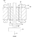
- FIG. 1 is a longitudinal sectional view showing the configuration of electric motor 100 according to Embodiment 1.
- Electric motor 100 is provided, for example, in a compressor of an air conditioner (for example, compressor 400 shown in FIG. 19, which will be described later).
- Electric motor 100 is, for example, a permanent magnet synchronous motor.
- the electric motor 100 has a rotor 1 and a stator 5 .
- the rotor 1 is attached to a shaft 60 as a rotating shaft.
- the shaft 60 is rotatably supported by bearings 61 and 62 provided in the compressor. That is, the shaft 60 is so-called supported on both sides.
- a compression mechanism 70 of a compressor is connected to one axial end of the shaft 60 (on the side of the bearing portion 61 in FIG. 1). The compression mechanism 70 compresses the refrigerant by transmitting the rotation of the electric motor 100 to the compression mechanism 70 .
- the stator 5 has a stator core 51 and windings 52 .
- the windings 52 are wound around teeth (not shown) of the stator core 51 .
- FIG. 2 is an enlarged sectional view showing the configuration of rotor 1 shown in FIG.
- the rotor 1 includes a first rotor core 11, a plurality (eg, two) of second rotor cores 21, and a plurality (eg, two) of second rotor cores 21.
- the balance weights 41 and 42 are provided to offset the imbalance of the centrifugal force generated during the operation of the compression mechanism 70.
- the balance weights 41, 42 are made of non-magnetic material.
- the balance weight 41 is arranged on the second rotor core 21 on the bearing portion 61 side, and the balance weight 42 is arranged on the second rotor core 21 on the bearing portion 62 side.
- the rotor 1 can also be realized by having at least one of the plurality of balance weights 41 and 42 .
- the permanent magnets 30 are attached to the first rotor core 11 , the second rotor core 21 and the third rotor core 22 .
- the permanent magnets 30 are embedded in the first rotor core 11 , the second rotor core 21 and the third rotor core 22 . Therefore, the rotor 1 is an IPM (Interior Permanent Magnet) type rotor.
- Permanent magnet 30 is, for example, a rare earth magnet.
- the rotor 1 has six permanent magnets 30, for example. Since one permanent magnet 30 constitutes one magnetic pole of the rotor 1, the number of poles of the rotor 1 is six. Note that the number of poles of the rotor 1 is not limited to six, and may be two or more.
- the first rotor core 11, the second rotor core 21 and the third rotor core 22 are each made of a plurality of electromagnetic steel sheets (not shown).
- the two second rotor cores 21 are arranged coaxially with the first rotor core 11 .
- the two second rotor cores 21 are arranged axially outside the first rotor core 11 .
- the first rotor core 11 is arranged between the two second rotor cores 21 .
- the second rotor core 21 is in contact with the first rotor core 11 .
- the second diameter R2 is the first diameter. is larger than the diameter R1.
- the third rotor core 22 is arranged adjacent to the second rotor core 21 .
- the third rotor core 22 is in contact with the second rotor core 21 .
- the outer diameter of the third rotor core 22 is the same as the outer diameter of the second rotor core 21 . Therefore, in the rotor 1, the second rotor core 21 and the third rotor core 22 constitute the large diameter portion 20 of the rotor 1, and the first rotor core 11 constitutes the small diameter portion of the rotor 1.
- a part 10 is constructed.
- both gaps g1 and g2 are preferably 1.0 mm or less. Therefore, a preferable range of the gap g2 is 0 mm ⁇ g2 ⁇ 1.0 mm, and a more preferable range is 0.3 mm ⁇ g2 ⁇ 1.0 mm. A preferable range of the gap g1 is g2 ⁇ g1 ⁇ 1.0 mm.
- FIG. 3 is a longitudinal sectional view showing the configuration of electric motor 101 according to Comparative Example 1. As shown in FIG. As shown in FIG. 3, electric motor 101 according to Comparative Example 1 differs from electric motor 100 according to Embodiment 1 in that the gap g2 between the rotor and stator 5 is constant in the axial direction. .
- the gap g1 between the small diameter portion 10 and the stator 5 is wider than the gap g2 between the large diameter portion 20 and the stator 5, as described above.
- FIG. 4 is an explanatory diagram illustrating the amount of deflection of the shaft 60 according to the first embodiment.
- the deflection angle of the shaft 60 viewed from the bearing portion 61 is ⁇ 1
- the axial length of the first rotor core 11 is L2
- the axial length of the second rotor core 21 on the bearing portion 61 side is Let the length be L1.
- the deflection angle of the shaft 60 viewed from the bearing portion 62 is ⁇ 2
- the length of the second rotor core 21 on the bearing portion 62 side is L3, the bearing portion 62 and the second rotor core 21 on the bearing portion 62 side
- the maximum displacement E is also expressed by the following equation (2).
- E (D2+L3+L2/2) ⁇ tan ⁇ 2 (2)
- the distance D1 and the distance D2 may not match due to the design.
- the gap g1 shown in FIG. 1 is larger than the maximum displacement amount E shown by the equations (1) and (2), even if the shaft 60 is bent, the first rotor core 11 and Contact with the stator core 51 can be prevented. Therefore, in Embodiment 1, the gap g1 satisfies both the following expressions (3) and (4). g1>(D1+L1+L2/2) ⁇ tan ⁇ 1 (3) g1>(D2+L3+L2/2) ⁇ tan ⁇ 2 (4)
- the portion of the second rotor core 21 on the bearing portion 61 side that is most displaced in the radial direction due to the deflection of the shaft 60 is the end portion of the second rotor core 21 on the bearing portion 62 side.
- the maximum amount of radial displacement of the second rotor core 21 on the bearing portion 61 side is F1
- the portion of the second rotor core 21 on the bearing portion 62 side that is most displaced in the radial direction due to the deflection of the shaft 60 is the end of the second rotor core 21 on the bearing portion 61 side.
- the maximum amount of radial displacement of the second rotor core 21 on the bearing portion 62 side is F2
- the maximum amount of displacement F2 is given by the following equation (6).
- F2 (D2+L3) ⁇ tan ⁇ 2 (6)
- the gap g2 shown in FIG. 1 must be larger than the maximum displacement amounts F1 and F2.
- the electric motor 100 needs to satisfy the following equations (7) and (8).
- the gap g2 between the second rotor core 21 and the stator 5 is narrower than the gap g1 between the first rotor core 11 and the stator 5, the feedback from the winding 52 (see FIG. 1) is reduced. Irreversible demagnetization may occur in the portion of the permanent magnet 30 inserted into the second rotor core 21 due to the magnetic flux of the magnetic field. A configuration for preventing irreversible demagnetization in the permanent magnet 30 in the electric motor 100 will be described below.
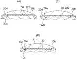
- FIG. 5 is a cross-sectional view showing part of the configuration of the second rotor core 21 shown in FIGS.
- the second rotor core 21 has a shaft insertion hole 20a into which the shaft 60 is inserted, and a plurality of magnet insertion holes 20b spaced apart in the circumferential direction C.
- the number of magnet insertion holes 20b corresponds to the number of poles of the rotor 1.
- the second rotor core 21 has six magnet insertion holes 20b.
- the number of magnet insertion holes 20b is not limited to six, and may be an even number of two or more.
- the magnet insertion holes 20b axially penetrate the second rotor core 21 .
- one permanent magnet 30 is inserted into one magnet insertion hole 20b.
- the shape of the magnet insertion hole 20b when viewed in the axial direction may be a V-shape with a protrusion facing radially inward or outward.
- two or more permanent magnets 30 may be inserted into one magnet insertion hole 20b.
- the inner surface of the magnet insertion hole 20b has a radially outward surface 20c as a first surface and a radially inward surface 20d as a second surface.
- the surface 20c and the surface 20d face each other.
- the surface 20c and the surface 20d are surfaces that define the magnet insertion hole 20b.
- w1 is the distance between the surface 20c and the surface 20d in the area where the permanent magnet 30 is inserted. In the vicinity of the end portion 30a of the permanent magnet 30, the distance between the surface 20c and the surface 20d in the region outside the end portion 30a facing the circumferential direction C of the permanent magnet 30 is w2.
- the spacing w2 is the same as the spacing w1.
- the second rotor core 21 is not provided with magnet holding portions (protrusions) that hold the permanent magnets 30 .
- the interval w2 may be larger than the interval w1.
- the spacing w1 and the spacing w2 should satisfy the following equation (9). w2 ⁇ w1 (9) Also, the rotor 1 can be realized by having one second rotor core 21 . That is, the rotor 1 only has to have at least one second rotor core 21 .
- FIG. 6 is a cross-sectional view showing the configuration of the third rotor core 22 shown in FIGS.
- the third rotor core 22 has a shaft insertion hole 20a into which the shaft 60 is inserted, and a plurality of magnet insertion holes 20b spaced apart in the circumferential direction C.
- FIG. 6 is a cross-sectional view showing the configuration of the third rotor core 22 shown in FIGS.
- the third rotor core 22 has a shaft insertion hole 20a into which the shaft 60 is inserted, and a plurality of magnet insertion holes 20b spaced apart in the circumferential direction C.
- the third rotor core 22 has a radially outward surface 22c and a radially inward surface 22d.
- the surface 22c and the surface 22d face each other in the radial direction.
- the surface 22c and the surface 22d are surfaces that define the magnet insertion hole 20b.
- the third rotor core 22 has a projecting portion 22e as a magnet holding portion facing the end portion 30a of the permanent magnet 30 in the circumferential direction C.
- the magnet insertion holes 20b of the second rotor core 21 are not provided with protrusions. Therefore, by providing the third rotor core 22 with the protrusions 22e, it is possible to restrict the movement of the permanent magnets 30 in the magnet insertion holes 20b. As a result, it is possible to prevent the occurrence of abnormal noise in the electric motor 100 and damage to the rotor 1 .
- the rotor 3 can be realized without the third rotor core 22, as shown in FIG. 15, which will be described later.
- the protrusion 22e protrudes radially outward from the surface 22c. Note that the projecting portion 22e may protrude radially inward from the surface 22d.
- the axial length L11 of the second rotor core 21 is longer than the axial length L12 of the third rotor core 22 .
- more second rotor cores 21 without protrusions are arranged than third rotor cores 22 with protrusions 22e. . Therefore, the occurrence of irreversible demagnetization in the permanent magnet 30 can be further prevented.
- FIG. 7 is a cross-sectional view showing the configuration of the first rotor core 11 shown in FIGS. 1 and 2.
- the first rotor core 11 includes a shaft insertion hole 10a into which the shaft 60 is inserted, and a plurality of (for example, six) magnet insertion holes 10a spaced apart in the circumferential direction C. and a hole 10b.
- One permanent magnet 30 is inserted into one magnet insertion hole 10b, like the magnet insertion hole 20b.
- the shape of the magnet insertion hole 10b when viewed in the axial direction may be a V-shape with a protrusion facing radially inward or outward.
- two permanent magnets 30 may be inserted into one magnet insertion hole 10b.
- the first rotor core 11 has a projecting portion 10e as a magnet holding portion facing the end portion 30a of the permanent magnet 30 facing the circumferential direction C within the magnet insertion hole 10b. Thereby, movement of the permanent magnet 30 in the magnet insertion hole 10b can be restricted.
- the movement of the permanent magnets 30 can be restricted by the projections 10e and the projections 22e provided on the third rotor core 22 described above. As a result, the occurrence of abnormal noise in the electric motor 100 and damage to the rotor 1 can be further prevented.
- the protrusion 10e is a protrusion that protrudes radially outward from a radially outward surface 10c that defines the magnet insertion hole 10b.
- the protrusion 10e may be a protrusion that protrudes radially inward from the radially inward surface 10d that defines the magnet insertion hole 10b.
- the rotor 1 includes the first rotor core 11 and the second rotor core 21 having an outer diameter larger than the outer diameter of the first rotor core 11. have Thereby, the gap g1 between the first rotor core 11 and the stator 5 becomes wider than the gap g2 between the second rotor core 21 and the stator 5. FIG. Therefore, even if the shaft 60 is bent due to the unbalanced centrifugal force due to the operation of the compression mechanism 70, the contact between the rotor 1 and the stator 5 can be prevented.
- the second rotor core 21 does not have projections facing the ends 30a of the permanent magnets 30 facing the circumferential direction C in the magnet insertion holes 20b.
- the magnetic flux from the windings 52 of the stator 5 can be prevented from demagnetizing the permanent magnets 30 due to concentration on the magnet holding portions. Therefore, irreversible demagnetization in the permanent magnet 30 due to the demagnetizing magnetic flux from the windings 52 of the stator 5 can be prevented. Therefore, according to Embodiment 1, it is possible to prevent the occurrence of irreversible demagnetization in the permanent magnets 30 while preventing contact between the rotor 1 and the stator 5 .
- the first rotor core 11 has projections 10e facing the ends 30a of the permanent magnets 30 facing the circumferential direction C within the magnet insertion holes 10b. Therefore, movement of the permanent magnet 30 in the magnet insertion hole 10b can be restricted. Therefore, it is possible to prevent the occurrence of abnormal noise in the electric motor 100 and damage to the rotor 1 .
- the first rotor core 11 is arranged between the two second rotor cores 21 .
- the first rotor core 11 is arranged in the axial center of the rotor 1, in the structure in which the shaft 60 is supported on both sides, the axial center where the amount of deflection is maximized , contact between the rotor 1 and the stator 5 can be prevented.
- the rotor 1 further has the third rotor core 22 arranged adjacent to the second rotor core 21 in the axial direction.
- the third rotor core 22 has protrusions 22e facing the ends 30a of the permanent magnets 30 facing the circumferential direction C in the magnet insertion holes 20b. Accordingly, in the rotor 1, the movement of the permanent magnets 30 can be restricted by the protrusions 10e and 22e. Therefore, the occurrence of abnormal noise in the electric motor 100 and damage to the rotor 1 can be further prevented.
- the axial length L11 of the second rotor core 21 is longer than the axial length L12 of the third rotor core 22 .
- more second rotor cores 21 without protrusions are arranged than third rotor cores 22 with protrusions 22e. . Therefore, the occurrence of irreversible demagnetization in the permanent magnet 30 can be further prevented.
- FIG. 8 is a longitudinal sectional view showing the configuration of electric motor 100A according to the modification of Embodiment 1.
- the same or corresponding components as those shown in FIG. 1 are given the same reference numerals as those shown in FIG.
- An electric motor 100A according to a modification of the first embodiment differs from the electric motor 100 according to the first embodiment in that the rotor 1A further has a fourth rotor core 12A.
- Electric motor 100A according to the modification of Embodiment 1 is the same as electric motor 100 according to Embodiment 1 except for this point.
- the electric motor 100A has a rotor 1A and a stator 5.
- the rotor 1A includes a first rotor core 11A, two second rotor cores 21, two third rotor cores 22, and a plurality (for example, two) of fourth rotor cores. 12A.
- the fourth rotor core 12A is arranged adjacent to the first rotor core 11A.
- the fourth rotor core 12A is arranged between the first rotor core 11A and the second rotor core 21.
- the first rotor core 11A and the two fourth rotor cores 12A constitute the small diameter portion 110 of the rotor 1A. Therefore, the diameter (that is, the outer diameter) of the fourth rotor core 12A is the same as the diameter (that is, the outer diameter) of the first rotor core 11A.
- the rotor 1A can also be realized by having one fourth rotor core 12A.
- FIG. 9(A) is a cross-sectional view showing part of the configuration of the second rotor core 21 shown in FIG.
- FIG. 9B is a cross-sectional view showing part of the configuration of the third rotor core 22 shown in FIG.
- the permanent magnets 30 are inserted into the magnet insertion holes 20b of the large-diameter portion 20 (see FIG. 8) of the rotor 1A.
- the projections 22 e to hold are not provided in the second rotor core 21 but are provided in the third rotor core 22 .
- irreversible demagnetization in the permanent magnet 30 due to the demagnetizing magnetic flux from the windings 52 (see FIG. 8) of the stator 5 can be prevented.
- FIG. 9(C) is a cross-sectional view showing part of the configuration of the first rotor core 11A shown in FIG. As shown in FIG. 9(C), the first rotor core 11A has magnet insertion holes 10b and protrusions 10e for holding the permanent magnets 30 in the magnet insertion holes 10b.
- FIG. 9(D) is a cross-sectional view showing part of the configuration of the fourth rotor core 12A shown in FIG.
- the inner surface of the magnet insertion hole 10b of the fourth rotor core 12A includes a radially outward surface 12c as a third surface and a radially outward surface 12c as a fourth surface. and an inward facing surface 12d.
- the faces 12c and 12d face each other.
- the surface 12c and the surface 12d are surfaces that define the magnet insertion hole 10b.
- the fourth rotor core 12A does not have projections facing the ends of the permanent magnets 30 facing the circumferential direction C in the magnet insertion holes 10b.
- the distance between the surface 12c and the surface 12d in the area where the permanent magnet 30 is inserted is w3, and the end 30a of the permanent magnet 30 near the end 30a of the permanent magnet 30 is w3.
- the space between the surface 12c and the surface 12d in the outer region is w4
- the space w4 is the same as the space w3.
- the small-diameter portion 110 of the rotor 1A is configured by the first rotor core 11A and the fourth rotor core 12A, so that the first rotor having the protrusions 10e in the small-diameter portion 110 Since the proportion occupied by the iron core 11A is reduced, the occurrence of irreversible demagnetization in the portion of the permanent magnet 30 inserted into the small diameter portion 110 can be prevented.
- the interval w4 may be larger than the interval w3. That is, the interval w4 and the interval w3 only need to satisfy the following formula (10). w4 ⁇ w3 (10)
- the rotor 1A has the fourth rotor core 12A arranged adjacent to the first rotor core 11A, and the fourth rotor The iron core 12A does not have a projection facing the end 30a of the permanent magnet 30 in the circumferential direction C within the magnet insertion hole 10b.
- the proportion of the first rotor core 11A having the projections 10e in the small diameter portion 110 of the rotor 1A is reduced, so that the portion of the permanent magnet 30 inserted into the small diameter portion 110 is irreversibly demagnetized. can be prevented from occurring.
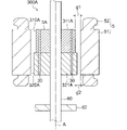
- FIG. 10 is a longitudinal sectional view showing the configuration of electric motor 200 according to the second embodiment. 10, the same or corresponding components as those shown in FIG. 1 are given the same reference numerals as those shown in FIG. Electric motor 200 according to Embodiment 2 differs from electric motor 100 according to Embodiment 1 in that rotor 2 is attached to shaft 60 that is cantilevered and in the configuration of rotor 2 . Electric motor 200 according to the second embodiment is the same as electric motor 100 according to the first embodiment except for this point.
- electric motor 200 has rotor 2 and stator 5 .
- Rotor 2 is attached to shaft 60 .
- shaft 60 is supported by one bearing 62 .
- the shaft 60 is cantilevered.
- the rotor 2 has a first rotor core 211 , a second rotor core 221 and a third rotor core 222 .
- each of the second rotor core 221 and the third rotor core 222 is larger than the outer diameter of the first rotor core 211. Therefore, in Embodiment 2, the first rotor core 211 constitutes the small-diameter portion 210 of the rotor 2 , and the second rotor core 221 and the third rotor core 222 constitute the large-diameter portion of the rotor 2 .
- a part 220 is constructed.
- the first rotor core 211 is located farther from the bearing 62 than the second rotor core 221 and the third rotor core 222 are.
- FIG. 11 is a longitudinal sectional view showing the configuration of electric motor 102 according to Comparative Example 2.
- electric motor 102 according to Comparative Example 2 is different from electric motor 200 according to Embodiment 2 in that gap g2 between rotor core 122 and stator 5 is constant in the axial direction. differ.
- Electric motor 102 according to Comparative Example 2 is the same as electric motor 200 according to Embodiment 2 in that shaft 60 is supported in a cantilever manner.
- the first rotor core 211 forming the small-diameter portion 210 is more closely connected to the bearing portions than the second rotor core 221 and the third rotor core 222 .
- 62 is located at a distance.
- the gap between the rotor 2 and the stator 5 is wide in the portion of the rotor 2 away from the bearing 62 in the axial direction.
- FIG. 12(A) is a cross-sectional view showing part of the configuration of the second rotor core 221 shown in FIG.
- FIG. 12B is a cross-sectional view showing part of the configuration of the third rotor core 222 shown in FIG.
- projections 22e holding permanent magnets 30 are provided on third rotor core 222 and not provided on second rotor core 221.
- FIG. 12A As a result, the portion of the permanent magnets 30 inserted into the second rotor core 221 can be prevented from being demagnetized by the demagnetizing magnetic flux from the windings 52 of the stator 5 .
- FIG. 12(C) is a cross-sectional view showing part of the configuration of the first rotor core 211 shown in FIG.
- the magnet insertion hole 10b of the first rotor core 211 has projections 10e that hold the permanent magnets 30 within the magnet insertion hole 10b. Thereby, movement of the permanent magnet 30 in the magnet insertion hole 10b can be restricted.
- the rotor 2 is attached to the shaft 60 that is cantilevered by the bearings 62 .
- the first rotor core 211 forming the small diameter portion 210 of the rotor 2 is arranged at a position farther from the bearing 62 than the second rotor core 221 and the third rotor core 222 are.
- contact between the rotor 2 and the stator 5 due to whirling of the shaft 60 can be prevented. Therefore, according to the second embodiment, even if the shaft 60 is cantilevered, it is possible to prevent irreversible demagnetization in the permanent magnet 30 while preventing contact between the rotor 2 and the stator 5. can be prevented.
- FIG. 13 is a vertical cross-sectional view showing the configuration of an electric motor 200A according to a modification of the second embodiment. 13, the same or corresponding components as those shown in FIG. 1 are given the same reference numerals as those shown in FIG. Electric motor 200A according to a modification of Embodiment 2 differs from electric motor 200 according to Embodiment 2 in the configuration of rotor 2A. Electric motor 200A according to the modification of the second embodiment is the same as electric motor 200 according to the second embodiment except for this point.
- the electric motor 200A has a rotor 2A and a stator 5.
- the rotor 2A includes a first rotor core 211A, a second rotor core 221, a third rotor core 222A, and a plurality of (two in FIG. 13) fourth rotor cores 212A.
- the fourth rotor core 212A is arranged adjacent to the first rotor core 211A.
- the two fourth rotor cores 212A are arranged on both axial sides of the first rotor core 211A.
- the diameter of the fourth rotor core 212A is the same as the diameter of the first rotor core 211A.
- Each diameter of the first rotor core 211A and the fourth rotor core 212A is smaller than each diameter of the second rotor core 221 and the third rotor core 222 .
- the first rotor core 211A and the fourth rotor core 212A constitute the small diameter portion 210A of the rotor 2A
- the second rotor core 221 and the third rotor core 221A constitute the small diameter portion 210A of the rotor 2A
- the child core 222 constitutes the large diameter portion 220 of the rotor 2A.
- FIG. 14(A) is a cross-sectional view showing the configuration of the second rotor core 221 shown in FIG.
- FIG. 14B is a cross-sectional view showing the configuration of the third rotor core 222 shown in FIG. 13.
- projections 22e for holding the permanent magnets 30 are provided on the third rotor core 222, is not provided in the rotor core 221.
- the portion of the permanent magnets 30 inserted into the second rotor core 221 can be prevented from being demagnetized by the demagnetizing magnetic flux from the windings 52 of the stator 5 .
- FIG. 14(C) is a cross-sectional view showing the configuration of the first rotor core 211A shown in FIG.
- FIG. 14D is a cross-sectional view showing the configuration of the fourth rotor core 212A shown in FIG. 13.
- FIG. 14S. 14C and 14D in the small diameter portion 210A (see FIG. 13), the protrusions 10e for holding the permanent magnets 30 are provided on the first rotor core 211A, It is not provided in the rotor core 212A.
- the rotor 2A has the fourth rotor core 212A arranged adjacent to the first rotor core 211A, and the fourth rotor The iron core 212A does not have a protrusion facing the end 30a of the permanent magnet 30 within the magnet insertion hole 10b.
- the proportion of the first rotor core 211A having the projections 10e in the small diameter portion 210A of the rotor 2A is reduced, so that the portion of the permanent magnet 30 inserted into the small diameter portion 210A is irreversibly demagnetized. can be prevented from occurring.
- FIG. 15 is a longitudinal sectional view showing the configuration of electric motor 300 according to the third embodiment. 15, the same or corresponding components as those shown in FIG. 1 are given the same reference numerals as those shown in FIG. Electric motor 300 according to Embodiment 3 differs from electric motor 100 according to Embodiment 1 in the configuration of rotor 3 . Electric motor 300 according to the third embodiment is the same as electric motor 100 according to the first embodiment except for this point.
- the electric motor 300 has a rotor 3 and a stator 5.
- the rotor 3 is attached to a shaft 60 that is both supported by bearings 61 and 62 .
- the rotor 3 has a first rotor core 311 and a plurality of (two in FIG. 15) second rotor cores 321 arranged axially outside the first rotor core 311. .
- each of the two second rotor cores 321 is larger than the diameter of the first rotor core 311.
- the first rotor core 311 constitutes the small diameter portion 310 of the rotor 3
- the second rotor core 321 constitutes the large diameter portion 320 of the rotor 3 .
- the gap g1 between the first rotor core 311 and the stator 5 is wider than the gap g2 between the second rotor core 321 and the stator 5. As a result, even when the shaft 60 supported on both sides is bent, the gap between the first rotor core 311 and the stator 5 is Since g1 is wide, contact between the rotor 3 and the stator 5 can be prevented.
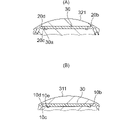
- FIG. 16(A) is a cross-sectional view showing part of the configuration of the second rotor core 321 shown in FIG.
- the second rotor core 321 does not have protrusions facing the ends 30a of the permanent magnets 30 in the circumferential direction C within the magnet insertion holes 20b.
- the large-diameter portion 320 of the rotor 3 is composed only of the second rotor core 321 without protrusions. Therefore, even if the gap g2 between the second rotor core 321 and the stator 5 is narrow, the permanent magnet 30 is prevented from being irreversibly demagnetized by the magnetic flux of the diamagnetic field from the winding 52 of the stator 5. This can be further prevented.
- FIG. 16(B) is a cross-sectional view showing part of the configuration of the first rotor core 311 shown in FIG. As shown in FIG. 16B, the first rotor core 311 has projections 10e for holding the permanent magnets 30 in the magnet insertion holes 10b. Thereby, movement of the permanent magnet 30 in the magnet insertion hole 10b can be restricted.
- the rotor 3 includes the first rotor core 311 and the second rotor core 321 having an outer diameter larger than the outer diameter of the first rotor core 311. have This makes the gap g1 between the first rotor core 311 and the stator 5 wider than the gap g2 between the second rotor core 321 and the stator 5 . Therefore, in a structure in which the shaft 60 is supported on both sides, even if the shaft 60 is bent due to the imbalance of the centrifugal force due to the operation of the compression mechanism 70, contact between the rotor 3 and the stator 5 is prevented. can.
- the large-diameter portion 320 of the rotor 3 is composed only of the second rotor core 321 without protrusions.
- FIG. 17 is a vertical cross-sectional view showing the configuration of an electric motor 300A according to a modification of the third embodiment. 17, the same or corresponding components as those shown in FIG. 15 are given the same reference numerals as those shown in FIG.
- An electric motor 300A according to a modification of the third embodiment differs from the electric motor 300 according to the third embodiment in that the rotor 3A is attached to a cantilevered shaft 60 and in the configuration of the rotor 3A. do.
- Electric motor 300A according to the modification of Embodiment 3 is the same as electric motor 300 according to Embodiment 3 except for this point.
- the electric motor 300A has a rotor 3A and a stator 5.
- the rotor 3A is attached to a shaft 60 that is cantilevered by a bearing 62.
- the rotor 3A has a first rotor core 311A and a second rotor core 321A.
- the first rotor core 311A is arranged at a position farther from the bearing portion 62 than the second rotor core 321A.
- the outer diameter of the second rotor core 321A is larger than the outer diameter of the first rotor core 311A. Therefore, the gap g1 between the first rotor core 311A and the stator 5 is wider than the gap g2 between the second rotor core 321A and the stator 5.
- the amount of deflection of the axial end portion of the shaft 60 axially away from the portion supported by the bearing portion 62 is maximum.
- the gap g2 between the first rotor core 311A, which is the small diameter portion 310A of the rotor 3A, and the stator 5 is wider than the gap g1 between the second rotor core 321A and the stator 5.
- FIG. 18(A) is a cross-sectional view showing part of the configuration of the second rotor core 321A shown in FIG.
- the second rotor core 321A does not have protrusions facing the ends 30a of the permanent magnets 30 in the circumferential direction C within the magnet insertion holes 20b.
- the large diameter portion 320A of the rotor 3A is configured only by the second rotor core 321A having no projections. Therefore, even when the gap g2 between the second rotor core 321 and the stator 5 is narrow, irreversible demagnetization occurs in the permanent magnet 30 due to the demagnetizing magnetic flux from the windings 52 of the stator 5. can be further prevented.
- FIG. 18(B) is a cross-sectional view showing part of the configuration of the first rotor core 311A shown in FIG. As shown in FIG. 18B, the first rotor core 311A has protrusions 10e for holding the permanent magnets 30 in the magnet insertion holes 10b. Thereby, movement of the permanent magnet 30 in the magnet insertion hole 10b can be restricted.
- the rotor 3A includes the first rotor core 311A and the second rotor core 321A having a diameter larger than that of the first rotor core 311A. and Thereby, the gap g1 between the first rotor core 311A and the stator 5 becomes wider than the gap g2 between the second rotor core 321A and the stator 5.
- FIG. Therefore, in a structure in which the shaft 60 is cantilevered, even if the shaft 60 is bent due to the imbalance of the centrifugal force due to the operation of the compression mechanism 70, contact between the rotor 3A and the stator 5 is prevented. can.
- the large-diameter portion 320A of the rotor 3A is composed only of the second rotor core 321A having no projections.
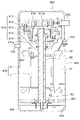
- FIG. 19 is a longitudinal sectional view showing the configuration of compressor 400 according to Embodiment 4.
- Compressor 400 is not limited to a scroll compressor, and may be another type of compressor.
- Compressor 400 includes compression mechanism 410 , electric motor 100 that drives compression mechanism 410 , shaft 60 that connects compression mechanism 410 and electric motor 100 , subframe 401 , and sealed container 402 .
- the compression mechanism 410 is an example of the compression mechanism 70 shown in FIG. 1 and the like.
- the compression mechanism 410 has a fixed scroll 411 , an orbiting scroll 412 , an Oldham ring 413 , a compliant frame 414 and a guide frame 415 .
- the fixed scroll 411 and the orbiting scroll 412 each have plate-like spiral teeth and are combined to form a compression chamber 416 .
- the fixed scroll 411 has a discharge port 411a for discharging the refrigerant compressed in the compression chamber 416.
- a suction pipe 405 that penetrates the sealed container 402 is press-fitted into the fixed scroll 411 .
- the sealed container 402 is provided with a discharge pipe 406 for discharging the high-pressure refrigerant gas discharged from the discharge port 411a to the outside. Further, the electric motor 100 is incorporated inside the sealed container 402 by shrink fitting. A glass terminal 407 for electrically connecting the stator 5 of the electric motor 100 and the drive circuit is fixed to the sealed container 402 by welding. A bottom portion 403 of the sealed container 402 is an oil reservoir portion in which refrigerating machine oil 404 is stored.
- the shaft 60 is rotatably supported by a main bearing portion 414 a provided on the compliant frame 414 and a bearing portion 62 as a sub-bearing portion provided on the sub-frame 401 .
- the main bearing portion 414a is an example of the bearing portion 61 shown in FIG. 1 and the like.
- the high-pressure refrigerant gas is discharged from the discharge port 411 a of the fixed scroll 411 into the sealed container 402 and discharged from the compressor 400 through the discharge pipe 406 .
- a portion of the refrigerant gas discharged from compression chamber 416 into sealed container 402 cools electric motor 100 by passing through a hole (not shown) provided in electric motor 100 .
- compressor 400 has electric motor 100 and compression mechanism 410 driven by electric motor 100 . As described in Embodiment 1, in electric motor 100, the occurrence of abnormal noise and reduction in output are prevented. Since the compressor 400 includes the electric motor 100, it is possible to prevent noise from being generated in the compressor 400 and to prevent the output of the compressor 400 from being lowered.
- FIG. 20 is a configuration diagram showing the configuration of an air conditioner 500 according to Embodiment 5.
- the refrigeration cycle device is not limited to the air conditioner 500, and may be applied to other devices such as a refrigerator or a heat pump cycle device.
- the air conditioner 500 includes an outdoor unit 501 and an indoor unit 502.
- the outdoor unit 501 and the indoor unit 502 are connected to each other by a gas pipe 503 and a liquid pipe 504, which are refrigerant pipes.
- the outdoor unit 501, the indoor unit 502, the gas pipe 503, and the liquid pipe 504 constitute a refrigerant circuit to circulate the refrigerant.
- a gas refrigerant which is a gaseous refrigerant, flows through the gas pipe 503 .
- a liquid refrigerant or a gas-liquid two-phase refrigerant flows through the liquid pipe 504 .
- the outdoor unit 501 has a compressor 400, an outdoor heat exchanger 511, an outdoor blower 512, and an expansion valve 513 as a decompression device.
- the compressor 400 can finely change the capacity of the compressor 400 (specifically, the amount of refrigerant delivered per unit time) by, for example, including an inverter device that arbitrarily changes the operating frequency.
- the outdoor heat exchanger 511 exchanges heat between the refrigerant and the outdoor air supplied from the outdoor blower 512 .
- the outdoor heat exchanger 511 functions as a condenser. Specifically, the outdoor heat exchanger 511 performs heat exchange between the refrigerant compressed by the compressor 400 and flowing in through the four-way valve and the outdoor air, and condenses and liquefies the refrigerant.
- the outdoor heat exchanger 511 functions as an evaporator. Specifically, the outdoor heat exchanger 511 exchanges heat between the low-temperature, low-pressure refrigerant flowing from the liquid pipe 504 through the expansion valve 513 and the outdoor air, and evaporates the refrigerant.
- the expansion valve 513 reduces the pressure of the refrigerant condensed by the condenser. Specifically, the expansion valve 513 expands the liquid refrigerant delivered from the condenser and delivers it as a low-temperature, low-pressure liquid refrigerant. For example, during cooling operation, the expansion valve 513 reduces the pressure of the refrigerant condensed by the outdoor heat exchanger 511 .
- the indoor unit 502 has an indoor heat exchanger 521 and an indoor fan 522 .
- the indoor heat exchanger 521 exchanges heat between the refrigerant and indoor air supplied from the indoor blower 522 .
- the indoor heat exchanger 521 functions as an evaporator.
- the indoor-side heat exchanger 521 sends out the evaporated refrigerant to the gas pipe 503 by exchanging heat between the low-temperature, low-pressure refrigerant and the indoor air.
- the indoor heat exchanger 521 functions as a condenser.
- the indoor heat exchanger 521 performs heat exchange between the refrigerant flowing from the gas pipe 503 and the air, thereby condensing and liquefying the refrigerant (or gas-liquid two-phase conversion), and the liquid pipe Send to 504.
- the air conditioner 500 includes the compressor 400 described in the fourth embodiment, the condenser that condenses the refrigerant compressed by the compressor 400, and the refrigerant that is condensed by the condenser. It has an expansion valve 513 for decompressing the refrigerant decompressed and an evaporator for evaporating the decompressed refrigerant by the expansion valve 513 .
- the compressor 400 can prevent a decrease in output while preventing noise from being generated. Therefore, by including the compressor 400, the air conditioning apparatus 500 can prevent a decrease in output while achieving noise reduction.
Landscapes
- Engineering & Computer Science (AREA)
- Power Engineering (AREA)
- Permanent Field Magnets Of Synchronous Machinery (AREA)
- Iron Core Of Rotating Electric Machines (AREA)
Priority Applications (2)
| Application Number | Priority Date | Filing Date | Title |
|---|---|---|---|
| JP2023534449A JPWO2023286125A1 (https=) | 2021-07-12 | 2021-07-12 | |
| PCT/JP2021/026129 WO2023286125A1 (ja) | 2021-07-12 | 2021-07-12 | 回転子、電動機、圧縮機及び冷凍サイクル装置 |
Applications Claiming Priority (1)
| Application Number | Priority Date | Filing Date | Title |
|---|---|---|---|
| PCT/JP2021/026129 WO2023286125A1 (ja) | 2021-07-12 | 2021-07-12 | 回転子、電動機、圧縮機及び冷凍サイクル装置 |
Publications (1)
| Publication Number | Publication Date |
|---|---|
| WO2023286125A1 true WO2023286125A1 (ja) | 2023-01-19 |
Family
ID=84919096
Family Applications (1)
| Application Number | Title | Priority Date | Filing Date |
|---|---|---|---|
| PCT/JP2021/026129 Ceased WO2023286125A1 (ja) | 2021-07-12 | 2021-07-12 | 回転子、電動機、圧縮機及び冷凍サイクル装置 |
Country Status (2)
| Country | Link |
|---|---|
| JP (1) | JPWO2023286125A1 (https=) |
| WO (1) | WO2023286125A1 (https=) |
Citations (5)
| Publication number | Priority date | Publication date | Assignee | Title |
|---|---|---|---|---|
| JPH11355985A (ja) * | 1998-06-04 | 1999-12-24 | Toshiba Corp | 永久磁石形モータ |
| JP2007181254A (ja) * | 2005-12-27 | 2007-07-12 | Mitsubishi Electric Corp | 永久磁石埋込型モータの回転子 |
| JP2013027157A (ja) * | 2011-07-21 | 2013-02-04 | Daikin Ind Ltd | インナーロータ型回転電機及び圧縮機 |
| JP2013093956A (ja) * | 2011-10-25 | 2013-05-16 | Mitsubishi Electric Corp | 密閉型圧縮機、その密閉型圧縮機を備えた冷凍サイクル装置、およびその冷凍サイクル装置を備えた空気調和機 |
| WO2014054688A1 (ja) * | 2012-10-04 | 2014-04-10 | 三菱電機株式会社 | 永久磁石埋込型電動機 |
-
2021
- 2021-07-12 WO PCT/JP2021/026129 patent/WO2023286125A1/ja not_active Ceased
- 2021-07-12 JP JP2023534449A patent/JPWO2023286125A1/ja not_active Withdrawn
Patent Citations (5)
| Publication number | Priority date | Publication date | Assignee | Title |
|---|---|---|---|---|
| JPH11355985A (ja) * | 1998-06-04 | 1999-12-24 | Toshiba Corp | 永久磁石形モータ |
| JP2007181254A (ja) * | 2005-12-27 | 2007-07-12 | Mitsubishi Electric Corp | 永久磁石埋込型モータの回転子 |
| JP2013027157A (ja) * | 2011-07-21 | 2013-02-04 | Daikin Ind Ltd | インナーロータ型回転電機及び圧縮機 |
| JP2013093956A (ja) * | 2011-10-25 | 2013-05-16 | Mitsubishi Electric Corp | 密閉型圧縮機、その密閉型圧縮機を備えた冷凍サイクル装置、およびその冷凍サイクル装置を備えた空気調和機 |
| WO2014054688A1 (ja) * | 2012-10-04 | 2014-04-10 | 三菱電機株式会社 | 永久磁石埋込型電動機 |
Also Published As
| Publication number | Publication date |
|---|---|
| JPWO2023286125A1 (https=) | 2023-01-19 |
Similar Documents
| Publication | Publication Date | Title |
|---|---|---|
| JP6584513B2 (ja) | 回転子、回転電機、電動圧縮機および冷凍空調装置 | |
| EP3540231B1 (en) | Compressor with noise damping | |
| US10879760B2 (en) | Permanent-magnet-embedded electric motor for compressor, compressor, and refrigeration cycle device | |
| WO2018203364A1 (ja) | ロータ、電動機、圧縮機および空気調和装置 | |
| JPWO2017072967A1 (ja) | 電動機、ロータ、圧縮機および冷凍空調装置 | |
| JP6824333B2 (ja) | 電動機、ロータ、圧縮機および冷凍空調装置 | |
| US11888353B2 (en) | Motor, compressor, and air conditioner | |
| JP2017028862A (ja) | 回転子、回転電機、電動圧縮機および冷凍空調装置 | |
| US20250015648A1 (en) | Rotating electrical machine, manufacturing method therefor, compressor, blower, and refrigeration device equipped with rotating electrical machine | |
| WO2023119404A1 (ja) | ロータ、モータ、圧縮機および冷凍サイクル装置 | |
| JP7403710B2 (ja) | 回転子、電動機、圧縮機及び空気調和装置 | |
| JP7237178B2 (ja) | ロータ、電動機、圧縮機、及び空気調和機 | |
| CN119948729A (zh) | 磁路部件、送风机、压缩机及制冷装置 | |
| JP7361921B2 (ja) | 電動機、圧縮機および冷凍サイクル装置 | |
| WO2023286125A1 (ja) | 回転子、電動機、圧縮機及び冷凍サイクル装置 | |
| JP7258140B2 (ja) | 回転子、電動機、圧縮機、及び空気調和機 | |
| AU2020444066B2 (en) | Rotor, motor, compressor, and air conditioner | |
| JP7789288B1 (ja) | ロータ、電動機、圧縮機および冷凍サイクル装置 | |
| JP7645480B2 (ja) | 電動機、圧縮機、及び機器 | |
| WO2026033675A1 (ja) | ロータ、モータ、圧縮機および冷凍サイクル装置 | |
| CN210265127U (zh) | 封闭型压缩机及制冷循环装置 | |
| WO2025126367A1 (ja) | ロータ、モータ、圧縮機および冷凍サイクル装置 | |
| WO2025191636A1 (ja) | ロータ、モータ、圧縮機および冷凍サイクル装置 | |
| WO2022180717A1 (ja) | 電動機、圧縮機および冷凍サイクル装置 | |
| JP2024147797A (ja) | 電動機、圧縮機、及び機器 |
Legal Events
| Date | Code | Title | Description |
|---|---|---|---|
| 121 | Ep: the epo has been informed by wipo that ep was designated in this application |
Ref document number: 21950069 Country of ref document: EP Kind code of ref document: A1 |
|
| WWE | Wipo information: entry into national phase |
Ref document number: 2023534449 Country of ref document: JP |
|
| NENP | Non-entry into the national phase |
Ref country code: DE |
|
| 122 | Ep: pct application non-entry in european phase |
Ref document number: 21950069 Country of ref document: EP Kind code of ref document: A1 |