WO2023282335A1 - 医療デバイスおよびシャント形成方法 - Google Patents
医療デバイスおよびシャント形成方法 Download PDFInfo
- Publication number
- WO2023282335A1 WO2023282335A1 PCT/JP2022/026999 JP2022026999W WO2023282335A1 WO 2023282335 A1 WO2023282335 A1 WO 2023282335A1 JP 2022026999 W JP2022026999 W JP 2022026999W WO 2023282335 A1 WO2023282335 A1 WO 2023282335A1
- Authority
- WO
- WIPO (PCT)
- Prior art keywords
- distal
- proximal
- shaft
- extension
- expandable body
- Prior art date
- Legal status (The legal status is an assumption and is not a legal conclusion. Google has not performed a legal analysis and makes no representation as to the accuracy of the status listed.)
- Ceased
Links
Images


Classifications
-
- A—HUMAN NECESSITIES
- A61—MEDICAL OR VETERINARY SCIENCE; HYGIENE
- A61B—DIAGNOSIS; SURGERY; IDENTIFICATION
- A61B18/00—Surgical instruments, devices or methods for transferring non-mechanical forms of energy to or from the body
- A61B18/04—Surgical instruments, devices or methods for transferring non-mechanical forms of energy to or from the body by heating
- A61B18/12—Surgical instruments, devices or methods for transferring non-mechanical forms of energy to or from the body by heating by passing a current through the tissue to be heated, e.g. high-frequency current
- A61B18/14—Probes or electrodes therefor
- A61B18/1492—Probes or electrodes therefor having a flexible, catheter-like structure, e.g. for heart ablation
-
- A—HUMAN NECESSITIES
- A61—MEDICAL OR VETERINARY SCIENCE; HYGIENE
- A61B—DIAGNOSIS; SURGERY; IDENTIFICATION
- A61B17/00—Surgical instruments, devices or methods
- A61B17/11—Surgical instruments, devices or methods for performing anastomosis; Buttons for anastomosis
-
- A—HUMAN NECESSITIES
- A61—MEDICAL OR VETERINARY SCIENCE; HYGIENE
- A61B—DIAGNOSIS; SURGERY; IDENTIFICATION
- A61B17/00—Surgical instruments, devices or methods
- A61B17/00234—Surgical instruments, devices or methods for minimally invasive surgery
- A61B2017/00238—Type of minimally invasive operation
- A61B2017/00243—Type of minimally invasive operation cardiac
- A61B2017/00247—Making holes in the wall of the heart, e.g. laser Myocardial revascularization
- A61B2017/00252—Making holes in the wall of the heart, e.g. laser Myocardial revascularization for by-pass connections, i.e. connections from heart chamber to blood vessel or from blood vessel to blood vessel
-
- A—HUMAN NECESSITIES
- A61—MEDICAL OR VETERINARY SCIENCE; HYGIENE
- A61B—DIAGNOSIS; SURGERY; IDENTIFICATION
- A61B17/00—Surgical instruments, devices or methods
- A61B2017/00535—Surgical instruments, devices or methods pneumatically or hydraulically operated
- A61B2017/00557—Surgical instruments, devices or methods pneumatically or hydraulically operated inflatable
-
- A—HUMAN NECESSITIES
- A61—MEDICAL OR VETERINARY SCIENCE; HYGIENE
- A61B—DIAGNOSIS; SURGERY; IDENTIFICATION
- A61B17/00—Surgical instruments, devices or methods
- A61B17/11—Surgical instruments, devices or methods for performing anastomosis; Buttons for anastomosis
- A61B2017/1107—Surgical instruments, devices or methods for performing anastomosis; Buttons for anastomosis for blood vessels
-
- A—HUMAN NECESSITIES
- A61—MEDICAL OR VETERINARY SCIENCE; HYGIENE
- A61B—DIAGNOSIS; SURGERY; IDENTIFICATION
- A61B17/00—Surgical instruments, devices or methods
- A61B17/11—Surgical instruments, devices or methods for performing anastomosis; Buttons for anastomosis
- A61B2017/1139—Side-to-side connections, e.g. shunt or X-connections
-
- A—HUMAN NECESSITIES
- A61—MEDICAL OR VETERINARY SCIENCE; HYGIENE
- A61B—DIAGNOSIS; SURGERY; IDENTIFICATION
- A61B18/00—Surgical instruments, devices or methods for transferring non-mechanical forms of energy to or from the body
- A61B2018/00053—Mechanical features of the instrument of device
- A61B2018/0016—Energy applicators arranged in a two- or three dimensional array
-
- A—HUMAN NECESSITIES
- A61—MEDICAL OR VETERINARY SCIENCE; HYGIENE
- A61B—DIAGNOSIS; SURGERY; IDENTIFICATION
- A61B18/00—Surgical instruments, devices or methods for transferring non-mechanical forms of energy to or from the body
- A61B2018/00053—Mechanical features of the instrument of device
- A61B2018/00214—Expandable means emitting energy, e.g. by elements carried thereon
- A61B2018/00267—Expandable means emitting energy, e.g. by elements carried thereon having a basket shaped structure
-
- A—HUMAN NECESSITIES
- A61—MEDICAL OR VETERINARY SCIENCE; HYGIENE
- A61B—DIAGNOSIS; SURGERY; IDENTIFICATION
- A61B18/00—Surgical instruments, devices or methods for transferring non-mechanical forms of energy to or from the body
- A61B2018/00315—Surgical instruments, devices or methods for transferring non-mechanical forms of energy to or from the body for treatment of particular body parts
- A61B2018/00345—Vascular system
- A61B2018/00351—Heart
- A61B2018/0038—Foramen ovale
-
- A—HUMAN NECESSITIES
- A61—MEDICAL OR VETERINARY SCIENCE; HYGIENE
- A61B—DIAGNOSIS; SURGERY; IDENTIFICATION
- A61B18/00—Surgical instruments, devices or methods for transferring non-mechanical forms of energy to or from the body
- A61B2018/00571—Surgical instruments, devices or methods for transferring non-mechanical forms of energy to or from the body for achieving a particular surgical effect
- A61B2018/00595—Cauterization
-
- A—HUMAN NECESSITIES
- A61—MEDICAL OR VETERINARY SCIENCE; HYGIENE
- A61B—DIAGNOSIS; SURGERY; IDENTIFICATION
- A61B18/00—Surgical instruments, devices or methods for transferring non-mechanical forms of energy to or from the body
- A61B18/04—Surgical instruments, devices or methods for transferring non-mechanical forms of energy to or from the body by heating
- A61B18/12—Surgical instruments, devices or methods for transferring non-mechanical forms of energy to or from the body by heating by passing a current through the tissue to be heated, e.g. high-frequency current
- A61B18/14—Probes or electrodes therefor
- A61B2018/1405—Electrodes having a specific shape
- A61B2018/142—Electrodes having a specific shape at least partly surrounding the target, e.g. concave, curved or in the form of a cave
-
- A—HUMAN NECESSITIES
- A61—MEDICAL OR VETERINARY SCIENCE; HYGIENE
- A61B—DIAGNOSIS; SURGERY; IDENTIFICATION
- A61B18/00—Surgical instruments, devices or methods for transferring non-mechanical forms of energy to or from the body
- A61B18/04—Surgical instruments, devices or methods for transferring non-mechanical forms of energy to or from the body by heating
- A61B18/12—Surgical instruments, devices or methods for transferring non-mechanical forms of energy to or from the body by heating by passing a current through the tissue to be heated, e.g. high-frequency current
- A61B18/14—Probes or electrodes therefor
- A61B2018/1475—Electrodes retractable in or deployable from a housing
Definitions
- the present invention relates to a medical device and a shunt forming method with an expandable body that expands in vivo.
- Chronic heart failure is known as one of the heart diseases. Chronic heart failure is broadly classified into systolic and diastolic failure based on indicators of cardiac function. Patients with diastolic insufficiency have enlarged and stiffened myocardium, which increases pressure in the left atrium and reduces the heart's ability to pump. This causes the patient to present symptoms of heart failure such as pulmonary edema. In addition, there is also a heart disease in which pulmonary hypertension or the like causes the blood pressure in the right atrium to rise and the pumping function of the heart to decline, resulting in symptoms of heart failure.
- shunt therapy which forms a shunt (through-hole) in the interatrial septum that serves as an escape route for elevated atrial pressure in these patients with heart failure, enabling alleviation of heart failure symptoms.
- Shunt therapy accesses the atrial septum via a transvenous approach to create a through hole of the desired size.
- a medical device for performing such a shunt treatment for the interatrial septum there is, for example, a device as described in Patent Document 1.
- the medical device described in Patent Document 1 sandwiches a biological tissue between two expandable bodies that are expandable around the axis of a long shaft, and an electrode section that is a plurality of energy transmission elements arranged in the circumferential direction of one of the expanders. are brought into contact with the biological tissue so as to be aligned in the circumferential direction of the hole of the biological tissue to be treated, and then energy is applied from the plurality of electrode portions to cauterize the biological tissue. If the thickness of the living tissue varies in the circumferential direction of the extension body, there is a possibility that the electrode portions sandwiching the thin portion of the living tissue may become separated from the living tissue. If the electrode section does not sufficiently abut on the tissue to be treated, sufficient energy cannot be applied to the living tissue, which may reduce the therapeutic effect.
- the present invention has been made to solve the above-mentioned problems, and aims to provide a medical device and a shunt forming method that can effectively cauterize living tissue with uneven thickness.
- a medical device for achieving the above object is a radially expandable and contractible expandable body having a distal end portion including a force receiving portion, and an elongated shaft having a distal end portion to which the proximal end of the expandable body is fixed. and a plurality of energy transmission elements provided along the extension body, disposed within the shaft section and protruding from the distal end of the shaft section and connectable to the force receiving section of the extension body.
- a traction shaft slidable with respect to the shaft portion; a radially outwardly convexly curved distal apex located proximally of the extension; and extending radially outwardly in a distal direction from the distal end of the shaft portion.
- a second extension that includes a proximal extension and a proximal apex that is disposed on the distal side of the proximal extension and is curved in a radially outward convex shape; is recessed radially inward; and a concave portion extending to connect the proximal side top portion and the distal side top portion and defining a receiving space capable of receiving living tissue when the expansion body is expanded, the concave portion extending radially.
- a bottom portion located on the innermost side of the bottom portion, a distal side upright portion extending radially outward from the tip of the bottom portion to the distal side top portion, and a proximal side extending radially outwardly from the base end of the bottom portion to the proximal side top portion an upright portion, wherein either the distal side upright portion or the proximal side upright portion has a plurality of energy transmissions in which the plurality of electrodes are arranged at approximately equal intervals in the circumferential direction of the extension body.
- the other of the distal side upright portion and the proximal side upright portion has a plurality of facing portions facing each of the plurality of energy transmission elements when the expansion body is expanded, and
- the side extension has a plurality of distal strut structures connected to the distal apex, and the proximal extension has a plurality of proximal strut structures connected to the proximal apex.
- a method of forming a shunt according to the present invention for achieving the above object is to provide an elongated body having a radially expandable and retractable expandable body having a distal end portion including a force receiving portion and a distal end portion to which the proximal end of the expandable body is fixed. a shaft portion, a plurality of energy transmission elements provided along the extension body, disposed inside the shaft portion and projecting from the distal end portion of the shaft portion and connected to the force receiving portion of the extension body.
- extension body includes a distal extension portion extending radially outward from the force receiving portion toward a proximal direction; a radially outwardly convexly curved distal apex located proximally of the extension; and extending radially outwardly in a distal direction from the distal end of the shaft portion.
- a second extension that includes a proximal extension and a proximal apex that is disposed on the distal side of the proximal extension and is curved in a radially outward convex shape; is recessed radially inward; and a concave portion extending to connect the proximal side top portion and the distal side top portion and defining a receiving space capable of receiving living tissue when the expansion body is expanded, the concave portion extending radially.
- a bottom portion located on the innermost side of the bottom portion, a distal side upright portion extending radially outward from the tip of the bottom portion to the distal side top portion, and a proximal side extending radially outwardly from the base end of the bottom portion to the proximal side top portion an upright portion, wherein either the distal side upright portion or the proximal side upright portion has a plurality of energy transmissions in which the plurality of electrodes are arranged at approximately equal intervals in the circumferential direction of the extension body.
- the other of the distal side upright portion and the proximal side upright portion has a plurality of facing portions facing each of the plurality of energy transmission elements when the expansion body is expanded, and
- the side extension has a plurality of distal strut structures connected to the distal apex, and the proximal extension has a plurality of proximal strut structures connected to the proximal apex.
- the distal strut structure when subjected to an axial force of the expander, the distal strut structure; right atrium and left atrium in the fossa ovalis using a medical device having a deformable portion that is more easily deformable than other portions of the proximal strut structure, the energy transmission element placement portion, and the opposing portion; a shunt forming method for forming a shunt that communicates with the inserting the contracted expansion body into a hole formed in the fossa ovalis, expanding the expansion body in the hole, and disposing the biological tissue surrounding the hole in the receiving space defined by the recess; By sliding the traction shaft in the proximal direction with respect to the shaft portion, the expansion body is compressed such that the distal side upright portion and the proximal side upright portion of the recess are brought closer to each other, thereby causing the deformation.
- the distance between the distal side upright portion and the proximal side upright portion changes in the circumferential direction of the expandable body according to the thickness of the living tissue surrounding the hole, and the distal side of the concave portion changes.
- the biological tissue is arranged such that the energy transmission element disposed along the upright portion or the proximal upright portion so as to face the recess is in close contact with the biological tissue and inhibits natural healing of the hole from closing. ablate the body tissue disposed in the receiving space using the energy transmission element in intimate contact with the body;
- the easily deformable portion is deformed when an axial force is applied to the expandable body, so that the receiving space at the circumferential position corresponding to the easily deformable portion is expanded. growing. Therefore, by deforming the easily deformable portion, the plurality of energy transmission elements arranged in the concave portion defining the receiving space can be brought into appropriate contact with the living tissue having variations in thickness. Therefore, the present medical device and shunt forming method can effectively cauterize living tissue with uneven thickness.
- the easily deformable portion may have lower bending rigidity than other portions of the distal strut structure, the proximal strut structure, the energy transmission element placement portion, and the facing portion. As a result, the easily deformable portion bends due to the axial force acting on the expansion body, so that the receiving space at the circumferential position corresponding to the easily deformable portion can be effectively enlarged.
- the easily deformable portion may have an opening penetrating the expansion body in a radial direction. Thereby, the easy-to-bend deformable portion can be easily set in the expandable body.
- the easily deformable portion may have a thin portion that is thinner in the radial direction of the expandable body than the adjacent portion of the expandable body. Therefore, the easy-to-bend deformable portion can be easily set in the expandable body. Moreover, it becomes easy to define the bending direction of the easily deformable portion.
- the easily deformable portion may have a flexible portion made of a material that is softer than the material of the adjacent portion of the expansion body. This makes it possible to easily reduce the bending rigidity of the easily deformable portion.
- the easily deformable portion may be sandwiched between rigid portions having higher bending rigidity than the easily deformable portion in the axial direction of the expandable body. As a result, stress can be concentrated on the easily deformable portion when a force in the axial direction acts on the expandable body, making it easier to bend the easily deformable portion.
- the easily deformable portion may have a curved portion that is curved in a natural state. As a result, stress can be concentrated on the bending portion when an axial force acts on the expandable body, making it easier to bend the easily deformable portion.
- an elongated shaft having, at its distal end, an expandable body that can be expanded and contracted in the radial direction, and a base end fixing portion to which the base end of the expander is fixed.
- a traction shaft disposed within the shaft portion and protruding from the distal end portion of the shaft portion and connected to the distal end portion of the extension and slidable relative to the shaft portion;
- a distal shaft portion extending from a base end portion of the expansion body to a distal end portion inside the expansion body; and an electrode portion provided along the expansion body.
- the recess has a bottom portion that is located on the innermost side in the radial direction and a tip-side upright portion that extends radially outward from the tip of the bottom portion. and a proximal side upright portion extending radially outward from the base end of the bottom portion, and the electrode portion extends along the distal side upright portion or the proximal side upright portion so as to face the receiving space.
- the traction shaft slides on the shaft portion in the proximal direction so that the distal side upright portion and the proximal side upright portion approach each other.
- the distal shaft portion is configured to apply a compressive force to the expandable body, and in the expanded state of the expandable body, the distal shaft portion includes a bendable flexible portion at an axially central portion and the flexible and a rigid base portion provided on the base end side of the flexible portion in the axial direction.
- an elongated shunt having, at its distal end, an expandable body that can be expanded and contracted in the radial direction, and a base end fixing portion to which the base end of the expander is fixed.
- a shaft portion a traction shaft disposed within the shaft portion and protruding from the distal end portion of the shaft portion and connected to the distal end portion of the extension body, the traction shaft being slidable relative to the shaft portion; , a distal shaft extending inside the extension from a proximal end to a distal end of the extension; and an electrode section provided along the extension.
- a shunt forming method for forming a shunt that communicates with the left atrium wherein, in the expanded state of the expansion body, the distal shaft portion has a flexible portion that is bendable at the center in the axial direction and a flexible portion that extends axially from the flexible portion.
- the medical device has a distal rigid portion provided on the distal side and a proximal rigid portion provided on the proximal side in the axial direction of the flexible portion, and the medical device is inserted into the right atrium from the inferior vena cava to remove the egg.
- the contracted expandable body is inserted into the hole formed in the crypt, and the expandable body is expanded within the hole to form a radially innermost bottom portion and a distal end side extending radially outward from the distal end of the bottom portion.
- the flexible portion is bent according to the thickness of the surrounding living tissue, and the bending of the flexible portion is arranged to face the concave portion along the distal side upright portion or the proximal side upright portion of the concave portion.
- the electrode portion is brought into close contact with the living tissue, and the living tissue arranged in the receiving space is cauterized using the electrode portion in close contact with the living tissue so as to inhibit closure of the hole due to natural healing. do.
- the distal shaft portion when the thickness of the living tissue with which the expandable body contacts varies along the circumferential direction, the distal shaft portion is adapted to the flexible portion according to the thickness of the living tissue.
- the extension body can be deformed so that the concave portions are in close contact with the thick and thin portions of the living tissue.
- the electrode portion can be reliably brought into close contact with the living tissue over the entire circumference.
- the distal rigid portion and the proximal rigid portion are formed of an outer cylinder through which the traction shaft is inserted, and the flexible portion is formed of portions of the traction shaft exposed from the distal rigid portion and the proximal rigid portion. may be made. Thereby, the rigidity of the distal rigid portion and the proximal rigid portion can be sufficiently ensured.
- the proximal rigid portion is formed of an outer cylinder through which the traction shaft is inserted, and the traction shaft is composed of the flexible portion exposed on the distal side in the axial direction from the rigid proximal portion, and the flexible portion on the distal side in the axial direction from the flexible portion. and a distal stiffener positioned at the . This makes it possible to reduce the number of outer cylinders and facilitate assembly.
- the distal rigid portion is formed of an outer cylinder through which the traction shaft is inserted, and the traction shaft is composed of the flexible portion exposed on the proximal side in the axial direction from the rigid distal portion and the proximal side on the proximal side in the axial direction from the flexible portion. and a proximal rigid portion positioned at the . This makes it possible to reduce the number of outer cylinders and facilitate assembly.
- the distal shaft portion may be formed of an outer cylinder through which the traction shaft is inserted, and the distal shaft portion may have the flexible portion, the distal rigid portion, and the proximal rigid portion. This makes it possible to reduce the number of outer cylinders while eliminating the need to machine the traction shaft.
- the traction shaft may have the flexible portion, the distal rigid portion, and the proximal rigid portion. As a result, since the distal end rigid portion and the proximal end rigid portion can be configured only by the traction shaft, the number of parts can be further reduced.
- FIG. 4 is a schematic diagram schematically showing a state in which an expander is placed in a through-hole of the interatrial septum;
- FIG. 4 is a cross-sectional view showing a state in which the balloon is inserted into the interatrial septum;
- FIG. 4 is a cross-sectional view showing a state in which the distal end of the medical device is inserted into the interatrial septum;
- FIG. 4 is a cross-sectional view showing a state in which the expander is placed in the interatrial septum;
- FIG. 10 is a cross-sectional view showing a state in which a plurality of energy transmission elements arranged in recesses of the expansion body are brought into close contact with living tissue; 4 is a flow chart for explaining a shunt forming method;
- FIG. 10 is a perspective view showing a modified example of the expansion body of the medical device according to the first embodiment, where (A) is the first modified example, (B) is the second modified example, (C) is the third modified example, and (D ) shows the fourth modification.
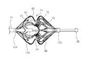
- FIG. 11 is an enlarged front view of the vicinity of the expander of the medical device according to the second embodiment;
- FIG. 11 is an enlarged front view of the vicinity of the expander of the medical device according to the second embodiment;
- FIG. 11 is an enlarged front view showing a simplified expansion body of the medical device according to the second embodiment
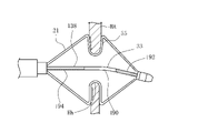
- FIG. 10 is a diagram showing a state in which the electrode section is pressed against the living tissue when the living tissue around the puncture hole has different thicknesses in the circumferential direction, and is an enlarged view showing the cross-section of the interatrial septum near the expander.
- FIG. 10 is a diagram showing a state in which the electrode portion is pressed against the living tissue around the puncture hole in the case where the living tissue around the puncture hole has different thicknesses in the circumferential direction in the medical device having the tip shaft portion according to the fifth modification of the second embodiment; be.
- FIG. 10 is a diagram showing a state in which the electrode portion is pressed against the living tissue around the puncture hole in the case where the living tissue around the puncture hole has different thicknesses in the circumferential direction in the medical device having the tip shaft portion according to the fifth modification of the second embodiment; be.
- FIG. 14 is a diagram showing a state in which the electrode portion is pressed against the living tissue around the puncture hole in the case where the living tissue around the puncture hole has different thicknesses in the circumferential direction in the medical device having the tip shaft portion according to the sixth modification of the second embodiment; be.
- FIG. 12 is a diagram showing a state in which the electrode portion is pressed against the living tissue around the puncture hole in the case where the living tissue around the puncture hole has different thicknesses in the circumferential direction in the medical device having the tip shaft portion according to the seventh modified example of the second embodiment; be.
- FIG. 12 is a diagram showing a state in which the electrode portion is pressed against the living tissue around the puncture hole in the case where the living tissue around the puncture hole has different thicknesses in the circumferential direction in the medical device having the tip shaft portion according to the seventh modified example of the second embodiment; be.
- FIG. 14 is a diagram showing a state in which the electrode portion is pressed against the living tissue around the puncture hole in the medical device having the tip shaft portion according to the eighth modification of the second embodiment, when the living tissue around the puncture hole has different thicknesses in the circumferential direction; be.
- FIG. 12B is a diagram showing a state in which the electrode section is pressed against the living tissue around the puncture hole in the medical device according to the ninth modification when the living tissue around the puncture hole has different thicknesses in the circumferential direction.
- distal side the side of a medical device that is inserted into a living body cavity
- proximal side the side of a medical device that is operated
- the medical device 10 expands the through hole Hh formed in the interatrial septum HA of the patient's heart H and maintains the expanded through hole Hh at that size. It is configured to be able to perform maintenance measures to
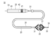
- the medical device 10 includes a long portion 20 extending from the proximal end to the distal end, an extension body 21 provided at the distal end of the long portion 20, and a long portion and an operation portion 23 connected to the proximal end portion of 20 .
- the extension body 21 is provided with an energy transmission element 22 (electrode portion) for performing the aforementioned maintenance procedure.
- the elongated portion 20 includes a shaft portion 31 holding the expansion body 21 at the distal end portion, an outer cylinder 30 housing the shaft portion 31, a traction shaft 33, and a traction shaft 33. It has a traction part 35 fixed to the tip of the.
- the shaft portion 31 is an elongate tubular body extending from the operating portion 23 to the extension body 21 .
- a proximal end portion of the shaft portion 31 is fixed to a distal end portion of the operation portion 23 .
- a distal end portion of the shaft portion 31 is fixed to a proximal end portion of the extension body 21 .
- the outer cylinder 30 is a long tubular body that covers the shaft portion 31, and can move back and forth with respect to the shaft portion 31 in the axial direction (in the direction of the axis of the long portion 20).
- the outer cylinder 30 can accommodate the contracted expansion body 21 in the interior thereof in a state of being moved to the distal end side of the elongated portion 20 .
- the expansion body 21 can be exposed by moving the outer cylinder 30 toward the base end side from the state in which the expansion body 21 is stored.
- the traction shaft 33 is an elongated tubular body arranged inside the shaft portion 31 and is axially movable forward and backward with respect to the shaft portion 31 .
- the traction shaft 33 protrudes distally from the distal end of the shaft portion 31 and protrudes distally from the distal end of the extension body 21 .
- a distal end portion of the pulling shaft 33 located on the distal side of the extension body 21 is fixed to the pulling portion 35 .
- a proximal end portion of the traction shaft 33 is led out from the operation portion 23 to the proximal end side.
- a guide wire lumen is formed along the axial direction inside the pulling shaft 33, through which the guide wire 11 (see FIGS. 5 to 7) can be passed.
- the pulling part 35 is an annular member fixed to the outer peripheral surface of the leading end of the pulling shaft 33 and protrudes radially outward from the outer peripheral surface of the pulling shaft 33 .
- the traction part 35 is not fixed to the extension body 21 .
- the outer diameter of the pulling part 35 is larger than the inner diameter of the distal end of the expansion body 21 . Therefore, the pulling portion 35 abuts on the distal end portion of the expandable body 21 from the distal end side, pulls the expandable body 21 in the proximal direction, and applies a compressive force compressing the shaft portion 31 along the axial direction to the expandable body 21 . can act on
- the operation unit 23 has a housing 40 gripped by the operator, a dial 41 that can be rotated by the operator, and a conversion mechanism 42 that converts rotation of the dial 41 into axial movement.
- Dial 41 is rotatably connected to housing 40 . A part of the dial 41 is exposed to the outside through the opening of the housing 40 so that the operator can operate it.
- the traction shaft 33 is held by the conversion mechanism 42 inside the operation portion 23 . As the dial 41 rotates, the conversion mechanism 42 can axially move the pulling shaft 33 it holds back and forth.
- a rack and pinion mechanism can be used as the conversion mechanism 42.
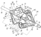
- the expandable body 21 includes a force receiving portion 51 arranged at the distal end of the expandable body 21, a base end connecting portion 52 arranged at the proximal end of the expandable body 21, and the force receiving portion 51. , a second extension 54 connected to the proximal connection 52, and a recess 55 disposed between the first extension 53 and the second extension 54. ing.
- the force receiving portion 51 has an annular shape and can receive a force directed toward the proximal direction from the traction portion 35 arranged on the distal side.
- the base end connecting portion 52 has an annular shape and is fixed to the distal end portion of the shaft portion 31 .
- the first extended portion 53 includes a distal extended portion 56 extending radially outward from the force receiving portion 51 toward the proximal direction, and a distal extended portion 56 arranged on the proximal side of the distal extended portion 56 and protruding radially outward. It has a curved distal apex 57 .
- the first extension portion 53 has a plurality of distal strut structures 60 extending radially outward from the force receiving portion 51 toward the proximal direction to form distal extension portions 56 .
- the plurality of distal strut structures 60 each include a first section 61 extending proximally from the force receiving portion 51 and a distal apex 57 extending proximally from the proximal end of the first section 61 . and a second section 62 that is
- Each first section 61 has a first strut 63 extending from the force receiving portion 51 substantially parallel to the axis of the extension body 21 when viewed from the radially outer side.
- Each second section 62 includes a plurality of second struts 64 bifurcated so as to spread in the circumferential direction of the extension body 21 while going from the proximal end of each first strut 63 toward the proximal direction, and the second struts 64 has a first junction 65 and a second junction 66 connected to the proximal end of the .
- the first merging portions 65 and the second merging portions 66 are alternately arranged in the circumferential direction of the expandable body 21 during expansion at approximately equal intervals.
- Each of the first merging portion 65 and the second merging portion 66 has two second struts 64 branching from each of the two first struts 63 adjacent in the circumferential direction and extending toward each other. formed by merging.
- first struts 63 are provided on the extension body 21 , twice as many as the energy transmission elements 22 .
- Twenty-four second struts 64 are provided on the extension body 21 , twice as many as the first struts 63 and four times as many as the energy transmission elements 22 . Note that the number of the first struts 63 and the number of the second struts 64 can be changed as appropriate.
- Each first confluence portion 65 is connected to the tip side top portion 57 arranged in the same phase as the energy transmission element 22 in the circumferential direction of the extension body 21 with an auxiliary curved portion 67 functioning as a cushioning portion interposed therebetween.
- the auxiliary curved portion 67 is curved in a wavy shape so as to be folded back multiple times when viewed from the outside in the radial direction.
- Each of the second confluences 66 is located at the tip side apex 57 arranged in a different phase in the circumferential direction of the extension body 21 with respect to the energy transmission element 22, and is substantially aligned with the axis of the extension body 21 when viewed from the radial outside. They are connected with connecting struts 68 extending in parallel.
- Each second strut 64 functions as an easily deformable portion that deforms more easily than the adjacent distal end portion.
- a first strut 63 (rigid portion) having higher rigidity than the second strut 64 is arranged on the distal end side of the second strut 64 (easily deformable portion).
- Two second struts 64 are connected via a first tip-side apex 69 to the tip side of the portion of the expansion body 21 where the energy transmission element 22 is arranged.
- the two second struts 64 are connected to the two first struts 63 arranged on the distal side. Therefore, the sum of the stiffnesses of the two second struts 64, which is the stiffness K1 of the easily deformable portion, is less than or equal to the sum of the stiffnesses of the two first struts 63, which is the stiffness K2 of the rigid portion, and is preferably smaller than the stiffness K2. .
- the width of the second strut 64 (the circumferential length of the extension body 21 ) is set smaller than the width of the first strut 63 in order to have such a second strut 64 .
- the thickness of the second struts 64 (the radial length of the expansion body 21 ) may be set smaller than the thickness of the first struts 63 .
- the rigidity K1 of the easily deformable portion is greater than the rigidity K3 of the first tip end side top portion 69 supported by the two second struts 64, is greater than the rigidity K4 of the one bottom connecting portion 83, and It is preferably greater than the stiffness K5 of one of the apexes forming the end-side apex 59 . This is because the bottom connecting portion 83, the first distal top portion 69 and the proximal top portion 59 need to be flexibly deformed in order for the expander 21 to expand.
- the position where the easily deformable portion is arranged is not limited to the second strut 64 of the distal strut structure 60 .
- the easily deformable portion can be arranged at a site other than the force receiving portion 51 , the proximal connecting portion 52 , the bottom portion 71 , the distal top portion 57 and the proximal top portion 59 of the expansion body 21 . Accordingly, the deformable portion is located on at least one of distal strut structure 60 , proximal strut structure 90 , energy transmission element placement portion 81 or opposing portion 82 .
- a rigid portion having higher rigidity than the second strut 64 and the first distal top portion 69 may be arranged between the second strut 64 (easily deformable portion) and the distal top portion 57 as well.
- the second strut 64 is sandwiched between the rigid portions having higher rigidity than the second strut 64 on the distal end side and the proximal end side, stress concentrates and the second strut 64 tends to bend.
- the distal apex 57 has a plurality of first distal apexes 69 connected to the auxiliary curved portions 67 and a plurality of second distal apexes 70 connected to the connecting struts 68 .
- the first distal apexes 69 and the second distal apexes 70 are alternately arranged in the circumferential direction of the expansion body 21 during expansion at approximately equal intervals.
- the concave portion 55 is recessed radially inward when the expansion body 21 is expanded, and extends so as to connect the proximal side top portion 59 and the distal side top portion 57 .
- the concave portion 55 defines a receiving space 74 that can receive living tissue when the expansion body 21 is expanded.
- the recessed portion 55 includes a bottom portion 71 located on the innermost side in the radial direction, a distal side upright portion 72 extending radially outward from the distal end of the bottom portion 71 to a distal side top portion 57 , and a base portion 71 extending from the base end of the bottom portion 71 to the proximal side top portion 59 . It has a base end side upright portion 73 extending radially outward.
- the recess 55 has a plurality of recessed strut structures 80 connected to a plurality of distal strut structures 60 via the distal apexes 57 .
- Each of the plurality of recessed strut structures 80 has an energy transfer element placement portion 81 located on the proximal upright portion 73 and a facing portion 82 located on the distal upright portion 72 , and has a pair of bottom portions 71 . It has a bottom connection portion 83 that connects the energy transmission element placement portion 81 and the facing portion 82 .
- Each bottom connecting portion 83 is arranged in a different phase from the first struts 63 in the circumferential direction of the expansion body 21 .
- the plurality of energy transmission element arrangement portions 81 are arranged at approximately equal intervals in the circumferential direction of the extension body 21 .
- the energy transmission element 22 is arranged on the surface forming the inner side of the recess 55 of each energy transmission element arrangement portion 81 .
- Each facing portion 82 faces each of the energy transmission elements 22 when the expansion body 21 is expanded.
- Each facing portion 82 includes a plurality of tip-side upright struts 84 branched into two while spreading toward the tip direction so as to substantially follow the circumferential direction of the expansion body 21 from the tip of each bottom connecting portion 83 , and a plurality of struts 84 . and a backrest portion 85 .
- Each of the second distal apexes 70 is formed by joining two distal standing struts 84 extending toward each other from two bottom connecting portions 83 disposed proximally and circumferentially adjacent to each other. .
- a plurality of backrest portions 85 connect two distal standing struts 84 branching from each of the bottom connecting portions 83 .
- the plurality of backrest portions 85 are arranged side by side from the side closer to the bottom portion 71 toward the side closer to the tip side top portion 57 .
- Each backrest portion 85 is curved such that the portion between the ends connected to the two distal standing struts 84 protrudes toward the distal top portion 57 .
- Each of the back support portions 85 is easy to bend on the side closer to the tip-side apex 57 with both ends connected to the tip-side upright struts 84 as fulcrums. Therefore, the back support portion 85 can be bent by a force directed toward the distal side received from the energy transmission element 22 arranged on the proximal side upright portion 73 .
- the living tissue sandwiched between the energy transmission element 22 and the back support portion 85 can be brought into close contact with the energy transmission element 22 .
- the backrest portion 85 closest to the tip-side top portion 57 is located on the first tip-side top portion 69 at a portion protruding toward the tip-side top portion 57. concatenated.
- the number of backrest portions 85 forming each facing portion 82 is not particularly limited.
- the second extended portion 54 includes a proximal side extended portion 58 extending radially outward toward the distal direction from the proximal connecting portion 52, and a radially outward convex shape disposed on the distal side of the proximal side extended portion 58. It has a curved proximal apex 59 .
- the proximal extension 58 has a plurality of proximal strut structures 90 .
- Each proximal strut structure 90 is arranged in phase with the plurality of energy transmission element arrangement portions 81 in the circumferential direction of the extension body 21 .
- Each of the plurality of proximal strut structures 90 includes a plurality of third struts 91 extending from the distal end of the shaft portion 31 to the proximal apex 59 substantially parallel to the axis of the expander 21 when viewed from the radially outer side. , and a plurality of secondary struts 92 connecting the third struts 91 adjacent in the circumferential direction.
- Each secondary strut 92 has two support struts 93 that are joined at joints 94 to each of two circumferentially adjacent third struts 91 .
- Two support struts 93 are connected at an angle between two joints 94 . Therefore, each secondary strut 92 is formed longer than the linear distance between the two joints 94 . Therefore, even if the distance between the two joints 94 becomes longer when the extension body 21 expands, the secondary strut 92 can change the angle between the two support struts 93 that constitute the secondary strut 92 . can continue to support two third struts 91. Therefore, the expansion body 21 can be expanded by the compressive force applied by the traction shaft 33 while spreading the third struts 91 at substantially equal intervals.
- the space between the proximal side upright portion 73 and the distal side upright portion 72 is slightly larger in the axial direction on the outer side than on the inner side in the radial direction when the expansion portion is expanded. This makes it easy to arrange the living tissue from the outside in the radial direction between the proximal side upright portion 73 and the distal side upright portion 72 .
- the energy transmission element 22 is arranged on the surface of the proximal side upright portion 73 facing the distal side when the expansion portion is expanded. Since the energy transmission element 22 is provided on the proximal upright portion 73, when the recess 55 clamps the interatrial septum HA, the energy from the energy transmission element 22 is directed toward the right atrial side of the interatrial septum HA. transmitted from Note that when the energy transmission element 22 is provided on the distal upright portion 72, the energy from the energy transmission element 22 is transmitted to the interatrial septum HA from the left atrium side.
- the energy transfer element 22 is composed of, for example, a bipolar electrode that receives electrical energy from an energy supply device (not shown), which is an external device. In this case, electricity is supplied between the energy transmission elements 22 arranged in each energy transmission element 22 arrangement portion.
- the energy transfer element 22 and the energy supply are connected by a wire (not shown) covered with an insulating coating.
- the conducting wire is led out through the elongated portion 20 and the operating portion 23 and connected to the energy supply device.
- the energy transfer element 22 may alternatively be configured as a monopolar electrode. In this case, electricity is supplied between the electrode and the counter electrode prepared outside the body. Alternatively, the energy transfer element 22 may be a heating element (electrode tip) that generates heat by receiving high-frequency electrical energy from an energy supply device. In this case, electricity is supplied between the energy transmission elements 22 arranged on each wire portion. Further, the energy transfer element 22 can be heated or cooled by microwave energy, ultrasonic energy, coherent light such as a laser, heated fluid, cooled fluid, chemical media, or can generate frictional heat. , a heater having an electric wire, etc., which can apply energy to the through hole Hh, and the specific form thereof is not particularly limited.
- the energy transmission element 22 is provided on the proximal side upright portion 73, and the back support portion 85 is provided on the distal side upright portion 72, respectively.
- a backrest portion 85 may be provided on each of the side upright portions 73 .
- the expansion body 21 is, for example, cut out from a cylinder and formed integrally.
- the struts forming extension 21 can be, for example, 50-500 ⁇ m thick and 0.3-2.0 mm wide. However, the struts forming extension 21 may have dimensions outside this range.
- the shape of the strut is not particularly limited, and may have, for example, a circular cross-sectional shape or other cross-sectional shape.
- the extension body 21 can be made of a metal material.
- the metal material for example, titanium-based (Ti--Ni, Ti--Pd, Ti--Nb--Sn, etc.) alloys, copper-based alloys, stainless steels, ⁇ -titanium steels, and Co--Cr alloys can be used. .
- an alloy having spring properties such as a nickel-titanium alloy.
- the material of the wire portion is not limited to these, and may be formed of other materials.
- the outer cylinder 30 and the shaft portion 31 of the elongated portion 20 are preferably made of a material having a certain degree of flexibility.
- materials include polyolefins such as polyethylene, polypropylene, polybutene, ethylene-propylene copolymers, ethylene-vinyl acetate copolymers, ionomers, or mixtures of two or more thereof, soft polyvinyl chloride resins, Polyamide, polyamide elastomer, polyester, polyester elastomer, polyurethane, fluororesin such as polytetrafluoroethylene, polyimide, PEEK, silicone rubber, latex rubber and the like.
- the traction shaft 33 and the traction section 35 are made of a long wire such as a superelastic alloy such as a nickel-titanium alloy or a copper-zinc alloy, a metal material such as stainless steel, or a relatively rigid resin material. be able to.
- the above may be formed by coating with a resin material such as polyvinyl chloride, polyethylene, polypropylene, ethylene-propylene copolymer, or fluororesin.
- This method of forming a shunt is performed on a patient suffering from heart failure (left heart failure). More specifically, as shown in FIG. 5, the myocardium in the left ventricle of the heart H is hypertrophied and stiffness (hardness) is increased, resulting in increased blood pressure in the left atrium HLa for a patient suffering from chronic heart failure. It is the method of treatment that is performed.
- the treatment method of the present embodiment comprises the steps of forming a through hole Hh in the interatrial septum HA (S1), placing the expander 21 in the through hole Hh (S2), and receiving the living tissue in the receiving space 74.
- Step (S3) a step (S4) of expanding the diameter of the through-hole Hh by the expander 21, a step (S5) of confirming hemodynamics in the vicinity of the through-hole Hh, and maintaining the size of the through-hole Hh and a step of confirming the hemodynamics in the vicinity of the through-hole Hh after the maintenance treatment (S7).
- the operator When forming the through hole Hh, the operator delivers an introducer in which a guiding sheath and a dilator are combined to the vicinity of the interatrial septum HA.
- the introducer can be delivered to the right atrium HRa, for example, via the inferior vena cava Iv.
- delivery of the introducer can be done using a guidewire 11 .
- the operator can pass the guidewire 11 through the dilator and deliver the introducer along the guidewire 11 .
- the insertion of the introducer into the living body, the insertion of the guide wire 11, and the like can be performed by a known method such as using an introducer for blood vessel introduction.
- step S1 the operator penetrates a puncture device (not shown) from the right atrium HRa side toward the left atrium HLa side to form a through hole Hh.
- a puncture device for example, a device such as a wire with a sharp tip can be used.
- a puncture device is passed through the dilator and delivered to the atrial septum HA. After removing the guidewire 11 from the dilator, the puncture device can be delivered to the interatrial septum HA instead of the guidewire 11 .
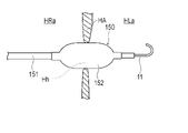
- the operator delivers the balloon catheter 150 to the vicinity of the interatrial septum HA along the pre-inserted guidewire 11 .
- the balloon catheter 150 has a balloon 152 at the tip of a shaft portion 151 . Once the balloon 152 is positioned in the interatrial septum HA, it is radially expanded to expand the through hole Hh.
- step S2 the medical device 10 is delivered near the interatrial septum HA along the pre-inserted guidewire 11 .
- the distal end of the medical device 10 penetrates the interatrial septum HA and reaches the left atrium HLa.
- the expansion body 21 is in a state of being housed in the outer cylinder 30 .
- step S3 the expansion body 21 is exposed by moving the outer cylinder 30 to the proximal end side.
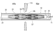
- the expansion body 21 is expanded in diameter, and the recess 55 is arranged in the through hole Hh of the interatrial septum HA to receive the living tissue surrounding the through hole Hh in the receiving space 74 .
- the through hole Hh is kept expanded by the expansion body 21 .
- step S4 the operator operates the operation part 23 with the interatrial septum HA received in the receiving space 74 of the recess 55 to move the traction shaft 33 to the proximal end side, as shown in FIG.
- the living tissue is sandwiched between the concave portions 55 of the expansion member 21 .
- the thickness of the interatrial septum HA may be uneven in the circumferential direction.
- Each of the plurality of recessed strut structures 80 having energy transfer element placement portion 81, bottom connecting portion 83 and facing portion 82 are independently deformable.
- a second strut 64 (easily deformable portion) is connected to the distal end side of each recessed strut structure 80 via a distal top portion 57 .
- each of the recessed strut structures 80 deforms the second struts 64 according to the thickness of the interatrial septum HA sandwiched by the recessed strut structures 80, while the gap between the energy transmission element placement portion 81 and the facing portion 82 is increased. can be changed independently. Therefore, the distance between the energy transmission element arrangement portion 81 and the opposing portion 82 of the concave strut structure 80 sandwiching the interatrial septum HA that is partially thick in the circumferential direction is equal to the distance between the recessed struts sandwiching the interatrial septum HA that is partially thin in the circumferential direction. It is greater than the separation distance between the energy transfer element placement portion 81 and the opposing portion 82 of the structure 80 .
- step S5 After placing the expansion body 21 in the through hole Hh, hemodynamics is confirmed in step S5.
- the operator delivers the hemodynamic confirmation device 100 to the right atrium HRa via the inferior vena cava Iv, as shown in FIG.
- the hemodynamic confirmation device 100 for example, a known echo catheter can be used.
- the operator can display the echo image acquired by the hemodynamic confirmation device 100 on a display device such as a display, and confirm the amount of blood passing through the through-hole Hh based on the display result.
- step S6 the operator performs maintenance treatment to maintain the size of the through-hole Hh.
- high-frequency energy is applied to the edge of the through-hole Hh through the energy transmission element 22 to cauterize (heat cauterize) the edge of the through-hole Hh with high-frequency energy.
- the energy transmission element 22 in contact with the thick part of the interatrial septum HA is in good contact with the other energy transmission elements 22 by deforming the second strut 64 corresponding to the energy transmission element 22 . Therefore, even if the thickness of the interatrial septum HA is non-uniform in the circumferential direction, all the energy transfer elements 22 arranged in the recesses 55 are in close contact with the interatrial septum HA. Therefore, the maintenance treatment can appropriately cauterize the entire circumferential edge of the through hole Hh. In addition, since the energy transfer element 22 to which the current is supplied can be prevented from being exposed to the blood vessel without coming into contact with the living tissue, the occurrence of thrombus can be suppressed.
- the through-hole Hh can maintain the shape when expanded by the expander 21 .
- step S7 After the maintenance treatment, the hemodynamics are confirmed again in step S7, and if the amount of blood passing through the through hole Hh is the desired amount, the operator reduces the diameter of the expandable body 21 and stores it in the outer cylinder 30. After that, it is removed from the through hole Hh. Furthermore, the entire medical device 10 is removed from the body, and the treatment is finished.
- the medical device 10 includes the radially expandable expandable body 21 having the distal end portion including the force receiving portion 51 and the distal end portion to which the proximal end of the expandable body 21 is fixed.
- an elongated shaft portion 31 a plurality of electrode portions (energy transmission elements 22) provided along the extension body 21, and arranged inside the shaft portion 31, protruding from the distal end portion of the shaft portion 31 and extended a traction shaft 33 connectable to the force receiving portion 51 of the body 21 and slidable relative to the shaft portion 31, the extension body 21 extending radially outward from the force receiving portion 51 in the proximal direction; a first extension portion 53 including a distal extension portion 56 extending to the rim of the shaft portion 31; a proximal side extension portion 58 extending radially outward from the distal end portion toward the distal direction; a proximal side top portion 59 disposed on the distal side of the proximal side extension portion 58 and curved radi
- the recess 55 having a radially innermost bottom portion 71, a distal upright portion 72 extending radially outward from the distal end of the bottom portion 71 to a distal top portion 57, a proximal upright portion 73 extending radially outward from the proximal end of the bottom portion 71 to the proximal top portion 59 , with either the distal upright portion 72 or the proximal upright portion 73 It has a plurality of energy transfer element arrangement portions 81 in which the plurality of electrode portions are arranged at substantially equal intervals in the direction, and the other of the distal side upright portion 72 and the proximal side upright portion 73 is the extension of the extension body 21 .
- the distal extension 56 has a plurality of distal strut structures 60 coupled to the distal apices 57 to provide a proximal
- the extension portion 58 has a plurality of proximal strut structures 90 connected to the proximal apex 59 and includes distal strut structures 60 , proximal strut structures 90 , energy transmission element locations 81 or opposing portions 82 .
- At least one of the distal strut structures 60, the proximal strut structures 90, the energy transfer element locating portion 81, and the opposing portion 82, when subjected to an axial force of the expander 21, is more likely to It has an easily deformable portion that is easily deformable, and by deformation of each easily deformable portion, a circumferential direction corresponding to the easily deformable portion It is possible that the position acceptance space 74 is large.
- the easily deformable portion is deformed when an axial force acts on the expandable body 21, so that the receiving space 74 at the circumferential position corresponding to the easily deformable portion becomes large. It is possible to become Therefore, by deforming the easily deformable portion, the plurality of energy transmission elements 22 arranged in the concave portion 55 that defines the receiving space 74 can be appropriately brought into close contact with the biological tissue that has variations in thickness. . Therefore, the medical device 10 can effectively cauterize living tissue with uneven thickness, and can suppress the formation of thrombus.
- the easily deformable portion has lower bending rigidity than other portions of the distal strut structure 60, the proximal strut structure 90, the energy transmission element arrangement portion 81, and the facing portion 82.
- an axial force acts on the expandable member 21 to bend the easily deformable portion, thereby effectively enlarging the receiving space 74 at the circumferential position corresponding to the easily deformable portion.
- the present invention also provides a shunt forming method.
- the shunt forming method uses the medical device 10 described above to form a shunt (through hole Hh) in the fossa ovalis that communicates the right atrium HRa and the left atrium HLa. It is inserted into the right atrium HRa from Iv, the contracted expansion body 21 is inserted into the through hole Hh formed in the fossa ovalis, the expansion body 21 is expanded within the through hole Hh, and the receptacle defined by the recess 55 is reached.
- a living tissue surrounding the through-hole Hh is placed in the space 74, and the traction shaft 33 is slid with respect to the shaft portion 31 in the proximal direction so that the distal side upright portion 72 and the proximal side upright portion 73 of the concave portion 55 are pulled apart.
- the expandable body 21 is compressed so that the two approach each other, and due to the deformation of the easily deformable portion, the distance between the distal end-side upright portion 72 and the proximal end-side upright portion 73 is reduced according to the thickness of the living tissue surrounding the through hole Hh.
- the shunt forming method configured as described above uses the energy transmission element 22 that is in close contact with the biological tissue that has variations in thickness by deforming the easily deformable portion when receiving the axial force of the expansion body 21.
- the living tissue placed in the receiving space 74 is cauterized.
- the shunt forming method can effectively cauterize living tissue with uneven thickness, and can suppress the formation of thrombi.
- the position where the easily deformable portion is arranged is not limited to the distal strut structure 60 , and may be arranged in the proximal strut structure 90 , the energy transmission element arrangement portion 81 or the facing portion 82 .
- the easily deformable portions may be arranged at two or more locations selected from the distal strut structure 60 , the proximal strut structure 90 , the energy transmission element arrangement portion 81 , or the facing portion 82 .
- proximal strut structure 90, the energy transmission element arrangement portion 81, the facing portion 82, and the distal strut structure 60 may be formed by a single strut that does not branch or merge.
- direction in which the deformable portion deforms is not particularly limited. Further, a part of the width of the strut may be changed so that the easily deformable portion is easily deformed when a certain force or more is applied.
- the thin portion 110 is a portion having a smaller geometrical moment of inertia than an adjacent portion of the expansion body 21 .
- the easy-to-bend deformable portion can be easily set in the expandable body 21 .
- Methods for forming the thin portion 110 include, for example, a method of reinforcing the portion of the extension body 21 other than the thin portion 110 with metal or resin, a method of swaging by applying a pressing force, a method of scraping, and the like.
- the easily deformable portion may be sandwiched between rigid portions 111 having higher bending rigidity than the easily deformable portion in the axial direction of the expandable body 21 .
- stress can be concentrated on the easily deformable portion when a force in the axial direction is applied to the expandable body 21, and the easily deformable portion can be easily bent.
- the easily deformable portion may have an opening 112 penetrating the expandable body 21 in the radial direction.
- the easy-to-bend deformable portion can be easily set in the expandable body 21 .
- openings that reduce the bending rigidity of the extension body 21 may also be formed in the distal top portion 57 , the proximal top portion 59 and the bottom portion 71 .
- the easily deformable portion may have a curved portion 113 that is curved in the natural state.
- the direction in which the bending portion 113 bends is not particularly limited, it is, for example, a direction along the radial direction of the extension body 21 .
- stress can be concentrated on the bending portion 113 when a force in the axial direction acts on the expandable body 21, making it easier to bend the easily deformable portion.
- the easily deformable portion may be the other of the distal strut structure 60, the proximal strut structure 90, the energy transfer element placement portion 81, and the opposing portion 82. It does not have to have a bending stiffness lower than that of the part.
- the easily deformable portion has a flexible portion 114 made of a material that is softer than the material of the adjacent portion of the expandable body 21.
- the flexible portion is made of resin, for example, and the portion adjacent to the flexible portion 114 is made of metal, for example.
- the easy-to-bend deformable portion can be easily set in the expandable body 21 .
- the shaft portion 31 includes a proximal fixing portion 131 to which the proximal end of the expandable body 21 is fixed, and a proximal end fixing portion 131 to which the distal end of the expandable body 21 is fixed. and a distal shaft portion 130 including a distal fixation portion 133 that The distal shaft portion 130 extends inside the expansion body 21 from the proximal end to the distal end of the expansion body 21 .
- symbol is attached
- the distal shaft portion 130 includes a flexible portion 160 that is bendable at the center in the axial direction when the extension body 21 is expanded, a rigid distal portion 162 that is provided on the distal side of the flexible portion 160 in the axial direction, and an axis of the flexible portion 160 . and a proximal rigid portion 164 provided on the direction proximal side.
- the distal rigid portion 162 and the proximal rigid portion 164 are formed of a rigid outer cylinder through which the traction shaft 33 can be inserted.
- the flexible portion 160 is formed by the portion of the traction shaft 33 exposed from the distal rigid portion 162 and the proximal rigid portion 164 . Since the traction shaft 33 is made of a bendable material, the flexible portion 160 can bend under force.
- the distal rigid portion 162 and the proximal rigid portion 164 are made of hard resin or metal, so that they do not bend even when the flexible portion 160 receives bending force, and maintains a straight state.
- the portions where the proximal end fixing portion 131 and the distal end fixing portion 133 of the expansion body 21 are arranged are binding portions where the plurality of wire portions 50 converge. It extends toward the center in the axial direction from the fixing portion 131 and the tip fixing portion 133 .
- the distal rigid portion 162 and the proximal rigid portion 164 have a length of at least 30% or more of the axial length of the portion of the wire portion 50 extending from the binding portion toward the recess 55 .
- a flexible portion 160 is arranged at a portion of the tip shaft portion 130 that faces the bottom portion 71 of the recess portion 55 in the radial direction when the expansion body 21 is expanded.
- a treatment method using the medical device 10 according to the second embodiment is substantially the same as the treatment method using the medical device 10 according to the first embodiment.
- the operator grasps the interatrial septum HA with the proximal side upright portion 73 and the distal side upright portion 72, and presses the electrode portion 22 against the living tissue.
- the living tissue around the puncture hole Hh has different thicknesses in the circumferential direction, as shown in FIG. It bends according to the thickness of the tissue.
- the concave portion 55 of the expandable body 21 is in close contact with the living tissue over the entire circumference. Therefore, the electrode section 22 (energy transmission element 22) can be reliably brought into close contact with the living tissue.
- the thickness of the body tissue on the upper side of the puncture hole Hh in the figure is large, and the thickness of the body tissue on the lower side of the puncture hole Hh in the figure is small.
- the flexible portion 160 of the distal shaft portion 130 bends downward in the figure according to the difference in the thickness of the living tissue.
- the concave portion 55 on the upper side of the expandable body 21 in the figure has a wider interval between the proximal side upright portion 73 and the distal side upright portion 72 in accordance with the large thickness of the living tissue, and the lower side in the figure of the expandable body 21 is formed.
- the distance between the proximal side upright portion 73 and the distal side upright portion 72 is narrowed according to the small thickness of the living tissue. Therefore, both the thick and thin portions of the living tissue are gripped by the recesses 55 with the same force, and each electrode portion 22 also adheres to the living tissue with the same force.
- the distal shaft portion 130 has a distal rigid portion 162 and a proximal rigid portion 164, and has a bendable flexible portion 160 in a portion facing the bottom portion 71 of the recess 55 in the radial direction.
- a curved shape can be formed in the central portion.
- the distal shaft portion 130 is entirely formed of the flexible portion 160, the distal shaft portion 130 cannot form a bent shape at the central portion in the axial direction, so that the concave portion 55 cannot grip the biological tissue at least in part in the circumferential direction.
- the distal shaft portion 130 has the distal rigid portion 162 and the proximal rigid portion 164, the distal shaft portion 130 has a bent shape at the central portion in the axial direction, and the concave portion 55 extends over the entire circumference of the living tissue.
- the expander 21 can be deformed to grip the .
- the distal rigid portion 162 and the proximal rigid portion 164 need to have a certain length. For this reason, the distal rigid portion 162 and the proximal rigid portion 164 have a length of at least 30% or more of the axial length of the portion where the wire rod portion 50 extends from the binding portion toward the concave portion 55 as described above. .
- the operator confirms hemodynamics (S5), inhibits occlusion of the puncture hole Hh due to natural healing, and performs maintenance treatment to maintain its size (S6).
- high-frequency energy is applied to the edge of the puncture hole Hh through the electrode section 22 to cauterize (heat cauterize) the edge of the puncture hole Hh with the high-frequency energy.
- High-frequency energy is applied by applying a voltage between a pair of electrode portions 22 adjacent in the circumferential direction. As described above, even if the thickness of the living tissue surrounding the puncture hole Hh varies in the circumferential direction, the distal shaft portion 130 is bent at the central portion in the axial direction so that the electrode portions 22 are evenly attached to the living tissue. Therefore, by applying a voltage to the electrode portion 22, energy can be reliably applied to the living tissue over the entire circumference.
- the tip shaft portion 136 of the fifth modification of the second embodiment includes a flexible portion 170 in the middle portion in the axial direction, a rigid tip portion 172 on the distal side of the flexible portion 170 , and and a proximal rigid portion 174 on the proximal side.
- the proximal rigid portion 174 is formed of a hard outer cylinder through which the traction shaft 33 is inserted.
- the traction shaft 33 has a flexible portion 170 exposed axially distally from the proximal rigid portion 174 and a distal rigid portion 172 disposed axially distally from the flexible portion 170 .
- the tip rigid portion 172 is formed on the traction shaft 33 .
- the rigid distal end portion 172 can be formed by covering the surface of the flexible pulling shaft 33 with a rigid cylindrical member. In this way, even when the distal rigid portion 172 is formed on the traction shaft 33, the flexible portion 170 of the distal shaft portion 136 is bent when the living tissue around the puncture hole Hh has different thicknesses in the circumferential direction.
- the expansion body 21 can be deformed along the direction so that the concave portion 55 has a shape corresponding to the thickness of the living tissue.
- the tip shaft portion 137 of the sixth modification of the second embodiment includes a flexible portion 180 in the middle portion in the axial direction, a rigid tip portion 182 on the distal side of the flexible portion 180 , and and a proximal rigid portion 184 on the proximal side.
- the tip rigid portion 184 is formed of a hard outer cylinder through which the traction shaft 33 is inserted.
- the traction shaft 33 has a flexible portion 180 exposed on the proximal side in the axial direction from the rigid distal end portion 182 and a rigid proximal end portion 184 arranged on the proximal side in the axial direction on the flexible portion 180 . That is, the proximal rigid portion 184 is formed on the traction shaft 33 .
- the puller shaft 33 can also be formed with a proximal rigid portion 184 .
- the tip shaft portion 138 of the seventh modification of the second embodiment includes a flexible portion 190 in the middle portion in the axial direction, a rigid tip portion 192 on the distal side of the flexible portion 190 , and and a proximal rigid portion 194 on the proximal side.
- a distal rigid portion 192 and a proximal rigid portion 194 are both formed on the traction shaft 33
- a flexible portion 190 is formed between the distal rigid portion 192 and the proximal rigid portion 194 .
- both a distal rigid portion 192 and a proximal rigid portion 194 may be formed on the traction shaft 33 .
- the tip shaft portion 139 of the eighth modification of the second embodiment includes a flexible portion 200 in the intermediate portion in the axial direction, a rigid tip portion 202 on the distal side of the flexible portion 200 , and and a proximal rigid portion 204 on the proximal side.
- the flexible portion 200, the distal rigid portion 202 and the proximal rigid portion 204 are all formed in an outer cylinder 206 through which the traction shaft 33 is inserted.
- the outer cylinder 206 is made of a hard material
- the flexible portion 200 is made of a flexible material.
- the outer cylinder 206 entirely from a hard material and providing a large number of slits or holes in the portion of the flexible portion 200, the flexible portion 200 that is easily bendable can be formed. In this manner, the flexible portion 200 , the distal rigid portion 202 and the proximal rigid portion 204 may all be formed in the outer cylinder 206 .
- the medical device 10 is an elongated body having, at its distal end, the expandable body 21 that can be expanded and contracted in the radial direction, and the proximal fixing portion 131 to which the proximal end of the expandable body 21 is fixed.
- a shaft portion 20, and a traction shaft 33 disposed inside the shaft portion 20, protruding from the distal end portion of the shaft portion 20 and connected to the distal end portion of the expansion body 21, and slidable relative to the shaft portion 20; a distal shaft portion 130 extending from the base end to the distal end of the extension body 21 inside the extension body 21; and an electrode section 22 provided along the extension body 21.
- the electrode section 22 has a distal side upright portion 72 extending radially outward and a proximal side upright portion 73 extending radially outward from the proximal end of the bottom portion 71 .
- the traction shaft 33 slides proximally relative to the shaft portion 20 so that the distal upright 72 and the proximal upright 73 are positioned along 72 or the proximal upright 73 . are configured to exert a compressive force on the expander 21 that compresses along the axis of the shaft portion 20 such that the shafts 20 approach each other.
- a flexible portion 160 that can be bent at the rim, a distal rigid portion 162 provided on the distal side in the axial direction of the flexible portion 160, and a rigid proximal end portion 164 provided on the proximal side in the axial direction of the flexible portion 160.
- the shunt forming method according to the second embodiment includes an elongated shaft portion 20 having an expandable body 21 that can be expanded and contracted in the radial direction and a base end fixing portion 131 to which the base end of the expandable body 21 is fixed.
- a traction shaft 33 disposed inside the shaft portion 20, protruding from the distal end portion of the shaft portion 20 and connected to the distal end portion of the extension body 21, and slidable with respect to the shaft portion 20;
- the medical device 10 including the distal shaft portion 130 extending inside the body 21 from the proximal end of the extension body 21 to the distal end thereof, and the electrode portion 22 provided along the extension body 21, the fossa ovalis right side of the fossa ovalis.
- the distal shaft portion 130 In a shunt forming method for forming a shunt that communicates between the atrium and the left atrium, in a state in which the expander 21 is expanded, the distal shaft portion 130 has a flexible portion 160 that is bendable at the central portion in the axial direction, and It has a distal rigid portion 162 provided on the distal end side in the axial direction and a rigid proximal end portion 164 provided on the proximal end side in the axial direction of the flexible portion 160, and the medical device 10 is inserted into the right atrium from the inferior vena cava.
- the contracted expansion body 21 into the hole formed in the fossa ovalis, expand the expansion body 21 in the hole, and expand the bottom portion 71 located on the innermost side in the radial direction and the bottom portion 71 radially outward from the tip of the bottom portion 71.
- the living tissue surrounding the hole is placed in the receiving space 74 defined by the recess 55 of the expander 21 , which includes the extending distal upright portion 72 and the proximal upright portion 73 extending radially outward from the proximal end of the bottom portion 71 .
- the flexible portion 160 bends according to the thickness of the living tissue surrounding the hole, and the bending of the flexible portion 160 causes the concave portion 55 to face the concave portion 55 along the distal side upright portion 72 or the proximal side upright portion 73 of the concave portion 55 .
- the electrode portion 22 is brought into close contact with the living tissue so as to prevent the pore from closing due to natural healing. cautery.
- the tip shaft portion 130 when the thickness of the living tissue with which the expandable body 21 contacts varies along the circumferential direction, the tip shaft portion 130 does not conform to the thickness of the living tissue. Accordingly, the expandable body 21 can be bent at the flexible portion 160 and deformed so that the concave portion 55 is in close contact with the thick portion and the thin portion of the living tissue. As a result, the electrode portion 22 can be reliably brought into close contact with the living tissue over the entire circumference.
- the distal rigid portion 162 and the proximal rigid portion 164 are formed of an outer cylinder through which the traction shaft 33 is inserted, and the flexible portion 160 is formed of the portion of the traction shaft 33 exposed from the distal rigid portion 162 and the proximal rigid portion 164. may be made. Thereby, the rigidity of the distal rigid portion 162 and the proximal rigid portion 164 can be sufficiently ensured.
- the rigid base end portion 74 is formed of an outer cylinder through which the traction shaft 33 is inserted. and a distal rigid portion 172 positioned at the . This makes it possible to reduce the number of outer cylinders and facilitate assembly.
- the rigid distal end portion 182 is formed of an outer cylinder through which the traction shaft 33 is inserted. and a proximal rigid portion 184 positioned at the . This makes it possible to reduce the number of outer cylinders and facilitate assembly.
- the distal shaft portion 139 may be formed of an outer cylinder through which the traction shaft 33 is inserted, and the distal shaft portion 139 may have a flexible portion 200 , a distal rigid portion 202 and a proximal rigid portion 204 . This makes it possible to reduce the number of outer cylinders while eliminating the need for machining the traction shaft 33 .
- the traction shaft 33 may have a flexible portion 190 , a distal rigid portion 192 and a proximal rigid portion 194 .
- the distal end rigid portion 192 and the proximal end rigid portion 194 can be configured only by the pulling shaft 33, the number of parts can be further reduced.
- the medical device 10 according to the first embodiment may include the distal shaft portions 130, 136, 137, 138, and 139 of the second embodiment.
- the medical device 10 according to the first embodiment includes the distal shaft portion 130 of the second embodiment.
- the distal shaft portion 130 includes a proximal fixing portion 131 to which the proximal end of the expandable body 21 is fixed, and a distal fixing portion 133 to which the distal end of the expandable body 21 is fixed.
- the distal shaft portion 130 has a flexible portion 160 , a distal rigid portion 162 provided axially distally of the flexible portion 160 , and a proximal rigid portion 164 provided axially proximally of the flexible portion 160 .
- the easily deformable portion deforms when the thickness of the living tissue with which the expander 21 contacts varies along the circumferential direction. Then, as the receiving space 74 at the position in the circumferential direction corresponding to the deformable portion becomes larger, the tip shaft portion 130 bends at the flexible portion 160 according to the thickness of the living tissue, and the portion where the living tissue has a large thickness.
- the expansion body 21 can be deformed so that the concave portions 55 are in close contact with the small portions. As a result, the electrode section 22 can be brought into more reliable contact with the living tissue over the entire circumference.
Landscapes
- Health & Medical Sciences (AREA)
- Surgery (AREA)
- Life Sciences & Earth Sciences (AREA)
- Engineering & Computer Science (AREA)
- Molecular Biology (AREA)
- Public Health (AREA)
- Heart & Thoracic Surgery (AREA)
- Medical Informatics (AREA)
- Nuclear Medicine, Radiotherapy & Molecular Imaging (AREA)
- Animal Behavior & Ethology (AREA)
- General Health & Medical Sciences (AREA)
- Biomedical Technology (AREA)
- Veterinary Medicine (AREA)
- Cardiology (AREA)
- Physics & Mathematics (AREA)
- Plasma & Fusion (AREA)
- Otolaryngology (AREA)
- Surgical Instruments (AREA)
Priority Applications (2)
| Application Number | Priority Date | Filing Date | Title |
|---|---|---|---|
| JP2023533193A JPWO2023282335A1 (https=) | 2021-07-09 | 2022-07-07 | |
| US18/398,992 US20240138907A1 (en) | 2021-07-09 | 2023-12-28 | Medical device and method for forming shunt |
Applications Claiming Priority (4)
| Application Number | Priority Date | Filing Date | Title |
|---|---|---|---|
| JP2021114254 | 2021-07-09 | ||
| JP2021-114254 | 2021-07-09 | ||
| JP2021-114256 | 2021-07-09 | ||
| JP2021114256 | 2021-07-09 |
Related Child Applications (1)
| Application Number | Title | Priority Date | Filing Date |
|---|---|---|---|
| US18/398,992 Continuation US20240138907A1 (en) | 2021-07-09 | 2023-12-28 | Medical device and method for forming shunt |
Publications (1)
| Publication Number | Publication Date |
|---|---|
| WO2023282335A1 true WO2023282335A1 (ja) | 2023-01-12 |
Family
ID=84800832
Family Applications (1)
| Application Number | Title | Priority Date | Filing Date |
|---|---|---|---|
| PCT/JP2022/026999 Ceased WO2023282335A1 (ja) | 2021-07-09 | 2022-07-07 | 医療デバイスおよびシャント形成方法 |
Country Status (3)
| Country | Link |
|---|---|
| US (1) | US20240138907A1 (https=) |
| JP (1) | JPWO2023282335A1 (https=) |
| WO (1) | WO2023282335A1 (https=) |
Cited By (3)
| Publication number | Priority date | Publication date | Assignee | Title |
|---|---|---|---|---|
| US12201354B1 (en) | 2024-04-01 | 2025-01-21 | Theraheart Inc. | Expandable ablation mechanisms for shunting catheters |
| WO2025090309A1 (en) * | 2023-10-27 | 2025-05-01 | Medtronic, Inc. | System for creating an interatrial shunt |
| WO2025212081A1 (en) * | 2024-04-01 | 2025-10-09 | Theraheart Inc. | Expandable ablation mechanisms for shunting catheters |
Citations (5)
| Publication number | Priority date | Publication date | Assignee | Title |
|---|---|---|---|---|
| JPH10509338A (ja) * | 1994-10-07 | 1998-09-14 | イーピー テクノロジーズ,インコーポレイテッド | 電極要素を支持するための可撓性構造 |
| WO2019189079A1 (ja) * | 2018-03-29 | 2019-10-03 | テルモ株式会社 | 医療デバイス |
| WO2019188917A1 (ja) * | 2018-03-29 | 2019-10-03 | テルモ株式会社 | 医療デバイス |
| WO2021065873A1 (ja) * | 2019-09-30 | 2021-04-08 | テルモ株式会社 | 医療デバイス |
| WO2021065874A1 (ja) * | 2019-09-30 | 2021-04-08 | テルモ株式会社 | 医療デバイス |
-
2022
- 2022-07-07 JP JP2023533193A patent/JPWO2023282335A1/ja active Pending
- 2022-07-07 WO PCT/JP2022/026999 patent/WO2023282335A1/ja not_active Ceased
-
2023
- 2023-12-28 US US18/398,992 patent/US20240138907A1/en active Pending
Patent Citations (5)
| Publication number | Priority date | Publication date | Assignee | Title |
|---|---|---|---|---|
| JPH10509338A (ja) * | 1994-10-07 | 1998-09-14 | イーピー テクノロジーズ,インコーポレイテッド | 電極要素を支持するための可撓性構造 |
| WO2019189079A1 (ja) * | 2018-03-29 | 2019-10-03 | テルモ株式会社 | 医療デバイス |
| WO2019188917A1 (ja) * | 2018-03-29 | 2019-10-03 | テルモ株式会社 | 医療デバイス |
| WO2021065873A1 (ja) * | 2019-09-30 | 2021-04-08 | テルモ株式会社 | 医療デバイス |
| WO2021065874A1 (ja) * | 2019-09-30 | 2021-04-08 | テルモ株式会社 | 医療デバイス |
Cited By (3)
| Publication number | Priority date | Publication date | Assignee | Title |
|---|---|---|---|---|
| WO2025090309A1 (en) * | 2023-10-27 | 2025-05-01 | Medtronic, Inc. | System for creating an interatrial shunt |
| US12201354B1 (en) | 2024-04-01 | 2025-01-21 | Theraheart Inc. | Expandable ablation mechanisms for shunting catheters |
| WO2025212081A1 (en) * | 2024-04-01 | 2025-10-09 | Theraheart Inc. | Expandable ablation mechanisms for shunting catheters |
Also Published As
| Publication number | Publication date |
|---|---|
| US20240138907A1 (en) | 2024-05-02 |
| JPWO2023282335A1 (https=) | 2023-01-12 |
Similar Documents
| Publication | Publication Date | Title |
|---|---|---|
| JP7270606B2 (ja) | 医療デバイス | |
| JP7595017B2 (ja) | 医療デバイス | |
| JP7270605B2 (ja) | 医療デバイス | |
| JP7543293B2 (ja) | 医療デバイス | |
| JP7513624B2 (ja) | 医療デバイス | |
| WO2023282335A1 (ja) | 医療デバイスおよびシャント形成方法 | |
| CN111936061A (zh) | 医疗设备以及处置方法 | |
| JP2022169816A (ja) | 医療デバイス | |
| US20240122645A1 (en) | Medical device and method for forming shunt | |
| JP7797477B2 (ja) | 医療デバイス | |
| JP7810697B2 (ja) | 医療デバイス | |
| WO2022071179A1 (ja) | 医療デバイスおよびシャント形成方法 | |
| JP2023112882A (ja) | 医療デバイスおよびシャント形成方法 | |
| EP4205676A1 (en) | Medical device | |
| JP7758590B2 (ja) | 医療デバイス | |
| WO2021193760A1 (ja) | 医療デバイス | |
| WO2021192914A1 (ja) | 医療デバイス | |
| JP2022136661A (ja) | 医療デバイス | |
| JP7735198B2 (ja) | 医療デバイスおよび医療システム | |
| WO2025173710A1 (ja) | 医療デバイス | |
| WO2023281887A1 (ja) | 医療デバイスおよびシャント形成方法 | |
| WO2026070589A1 (ja) | 医療デバイス | |
| WO2025070032A1 (ja) | 医療デバイス | |
| JP2022141102A (ja) | 医療デバイスおよびその使用方法 | |
| JP2022038122A (ja) | 医療デバイスおよびシャント形成方法 |
Legal Events
| Date | Code | Title | Description |
|---|---|---|---|
| 121 | Ep: the epo has been informed by wipo that ep was designated in this application |
Ref document number: 22837749 Country of ref document: EP Kind code of ref document: A1 |
|
| WWE | Wipo information: entry into national phase |
Ref document number: 2023533193 Country of ref document: JP |
|
| NENP | Non-entry into the national phase |
Ref country code: DE |
|
| 122 | Ep: pct application non-entry in european phase |
Ref document number: 22837749 Country of ref document: EP Kind code of ref document: A1 |