WO2023281805A1 - 通信システム、コントロールシステム、及び通信方法 - Google Patents
通信システム、コントロールシステム、及び通信方法 Download PDFInfo
- Publication number
- WO2023281805A1 WO2023281805A1 PCT/JP2022/007885 JP2022007885W WO2023281805A1 WO 2023281805 A1 WO2023281805 A1 WO 2023281805A1 JP 2022007885 W JP2022007885 W JP 2022007885W WO 2023281805 A1 WO2023281805 A1 WO 2023281805A1
- Authority
- WO
- WIPO (PCT)
- Prior art keywords
- unit
- data sets
- data set
- read
- order
- Prior art date
- Legal status (The legal status is an assumption and is not a legal conclusion. Google has not performed a legal analysis and makes no representation as to the accuracy of the status listed.)
- Ceased
Links
Images


Classifications
-
- G—PHYSICS
- G05—CONTROLLING; REGULATING
- G05B—CONTROL OR REGULATING SYSTEMS IN GENERAL; FUNCTIONAL ELEMENTS OF SUCH SYSTEMS; MONITORING OR TESTING ARRANGEMENTS FOR SUCH SYSTEMS OR ELEMENTS
- G05B19/00—Program-control systems
- G05B19/02—Program-control systems electric
- G05B19/418—Total factory control, i.e. centrally controlling a plurality of machines, e.g. direct or distributed numerical control [DNC], flexible manufacturing systems [FMS], integrated manufacturing systems [IMS] or computer integrated manufacturing [CIM]
- G05B19/4185—Total factory control, i.e. centrally controlling a plurality of machines, e.g. direct or distributed numerical control [DNC], flexible manufacturing systems [FMS], integrated manufacturing systems [IMS] or computer integrated manufacturing [CIM] characterised by the network communication
-
- G—PHYSICS
- G05—CONTROLLING; REGULATING
- G05B—CONTROL OR REGULATING SYSTEMS IN GENERAL; FUNCTIONAL ELEMENTS OF SUCH SYSTEMS; MONITORING OR TESTING ARRANGEMENTS FOR SUCH SYSTEMS OR ELEMENTS
- G05B19/00—Program-control systems
- G05B19/02—Program-control systems electric
- G05B19/418—Total factory control, i.e. centrally controlling a plurality of machines, e.g. direct or distributed numerical control [DNC], flexible manufacturing systems [FMS], integrated manufacturing systems [IMS] or computer integrated manufacturing [CIM]
- G05B19/4189—Total factory control, i.e. centrally controlling a plurality of machines, e.g. direct or distributed numerical control [DNC], flexible manufacturing systems [FMS], integrated manufacturing systems [IMS] or computer integrated manufacturing [CIM] characterised by the transport system
- G05B19/41895—Total factory control, i.e. centrally controlling a plurality of machines, e.g. direct or distributed numerical control [DNC], flexible manufacturing systems [FMS], integrated manufacturing systems [IMS] or computer integrated manufacturing [CIM] characterised by the transport system using automatic guided vehicles [AGV]
-
- H—ELECTRICITY
- H04—ELECTRIC COMMUNICATION TECHNIQUE
- H04L—TRANSMISSION OF DIGITAL INFORMATION, e.g. TELEGRAPHIC COMMUNICATION
- H04L47/00—Traffic control in data switching networks
- H04L47/10—Flow control; Congestion control
- H04L47/34—Flow control; Congestion control ensuring sequence integrity, e.g. using sequence numbers
-
- G—PHYSICS
- G05—CONTROLLING; REGULATING
- G05B—CONTROL OR REGULATING SYSTEMS IN GENERAL; FUNCTIONAL ELEMENTS OF SUCH SYSTEMS; MONITORING OR TESTING ARRANGEMENTS FOR SUCH SYSTEMS OR ELEMENTS
- G05B2219/00—Program-control systems
- G05B2219/20—Pc systems
- G05B2219/23—Pc programming
- G05B2219/23115—Buffer
Definitions
- the present disclosure relates to communication systems, control systems, and communication methods.
- Patent Document 1 discloses a system including a robot, a processing device, a robot controller that controls the robot, a processing device controller that controls the processing device, and a programmable logic controller that generates commands for the robot controller and the processing device controller. disclosed.
- the present disclosure provides a communication system effective for utilizing multiple data sets received via communication in proper order.
- a communication system includes an information addition unit that adds order information to each of a plurality of data sets, a transmission unit that sequentially transmits a plurality of data sets to which the order information is added, and from the transmission unit A receiving unit that sequentially receives a plurality of data sets, an arranging unit that arranges the plurality of data sets received by the receiving unit in a waiting buffer in order based on order information, and a plurality of data sets stored in the waiting buffer and a reading unit that sequentially reads the data in the order in which the data is read.
- a control system includes the communication system described above, a controller that sequentially generates a plurality of command data sets, and a local controller that operates a machine based on the plurality of command data sets, and an information addition unit adds order information to each of the plurality of command data sets generated by the controller, the transmitting unit sequentially transmits the plurality of command data sets to which the order information is added, and the receiving unit transmits the plurality of command data sets.
- the sequence is received, the arranging unit arranges the plurality of command data sets received by the receiving unit in the waiting buffer in the order based on the order information, and the reading unit arranges the plurality of command data sets stored in the waiting buffer.
- the local controller operates the machine based on the plurality of command data sets read by the read section.
- a communication method includes adding order information to each of a plurality of data sets, sequentially transmitting the plurality of data sets to which the order information is added by a transmitting unit, By sequentially receiving a plurality of data sets from the transmitting unit, arranging the plurality of data sets received by the receiving unit in a waiting buffer in an order based on the order information, and a plurality of data stored in the waiting buffer and sequentially reading the set in an arranged order.
- FIG. 1 is a schematic diagram illustrating a communication system
- FIG. 1 is a schematic diagram illustrating the configuration of a robot
- FIG. 3 is a block diagram illustrating functional configurations of a control server and communication devices
- FIG. 3 is a block diagram illustrating functional configurations of a communication device and a local device
- FIG. 3 is a schematic diagram illustrating the storage contents of a receive buffer and the storage contents of a standby buffer
- It is a block diagram which shows the modification of a communication apparatus and a local device.
- FIG. 11 is a block diagram showing a modification of the control server and communication device
- FIG. 11 is a block diagram showing a further modified example of the control server
- 3 is a block diagram illustrating the hardware configuration of a control server and communication devices;
- FIG. 4 is a flow chart illustrating a procedure for generating and transmitting a command data set
- FIG. 10 is a flow chart illustrating an arrangement procedure for multiple command data sets
- FIG. 4 is a flow chart illustrating a communication procedure
- 4 is a flow chart illustrating a local control procedure
- FIG. 10 is a flow chart illustrating an ordering procedure for multiple feedback data sets
- FIG. 4 is a flow chart illustrating a communication procedure
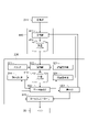
- a communication system 1 shown in FIG. 1 is a system that performs communication of a plurality of data sets between a supply application that supplies a plurality of data sets and a utilization application that uses the supplied plurality of data sets.
- the order of transmission of multiple data sets and the order of reception of multiple data sets may change. For example, an earlier transmitted data set may be received later than a later transmitted data set. Such replacement occurs irregularly. Therefore, when multiple data sets are communicated between the supplying application and the consuming application, the multiple data sets may not be used in the proper order in the consuming application.
- the communication system 1 adds order information to each of the plurality of data sets, sequentially transmits the plurality of data sets to which the order information is added, and sequentially receives the transmitted plurality of data sets. arranging the plurality of data sets received in the waiting buffer in the order based on the order information; and sequentially reading the plurality of data sets stored in the waiting buffer in the arranged order. is configured to
- the communication system 1 is applicable to various systems in which communication is performed between supply applications and utilization applications. In the following, the case where the communication system 1 is applied to the control system 10 will be exemplified in detail.
- the control system 10 includes a communication system 1, a controller 111 that sequentially generates a plurality of command data sets, and a local controller 315 that operates the machine 30 based on the plurality of command data sets.
- the communication system 1 applied to the control system 10 adds order information to each of the plurality of command data sets generated by the controller 111 and sequentially transmits the plurality of command data sets to which the order information is added. , sequentially receiving the plurality of transmitted command data sets, arranging the received plurality of command data sets in a waiting buffer in an order based on the order information, and arranging the plurality of command data sets stored in the waiting buffer sequentially reading in the order in which they are arranged;
- the local controller 315 operates the machine 30 based on command data sets sequentially read by the communication system 1 . In communicating multiple command data sets, controller 111 is the supplying application and local controller 315 is the utilizing application.
- the control system 10 may comprise a plurality of local controllers 315 that respectively operate a plurality of machines 30 and a plurality of controllers 111 that respectively correspond to the plurality of local controllers 315 .
- the machine 30 is a machine that implements actions. Although the type of machine 30 is not particularly limited, two types of machines 30A and 30B are illustrated in FIG.
- the machine 30A is a mobile robot that works on a work while moving. For example, machine 30A has automatic guided vehicle 31 and robot 40 . The automatic guided vehicle 31 is driven by the local controller 315 to move.
- the robot 40 is installed on the unmanned guided vehicle 31.
- the robot 40 is driven by the local controller 315 to carry out work such as transportation, processing, and assembly of the work.
- the robot 40 is, for example, a vertically articulated industrial robot. As shown in FIG. 2 , the robot 40 has a base portion 41 , a turning portion 42 , a first arm 43 , a second arm 44 , a wrist portion 45 and a tip portion 46 .
- the base 41 is installed on the automatic guided vehicle 31 .
- the swivel part 42 is mounted on the base part 41 so as to be rotatable around the vertical axis 51 .
- the robot 40 has a joint 61 that attaches the pivot 42 to the base 41 so as to be rotatable about the axis 51 .
- the first arm 43 is connected to the swivel portion 42 so as to be rotatable about an axis 52 that intersects (for example, is perpendicular to) the axis 51 .
- the robot 40 has a joint 62 that connects the first arm 43 to the pivot 42 so as to be rotatable about the axis 52 .
- An intersection includes being in a twisted relationship, such as a so-called overpass. The same applies to the following.
- the first arm 43 extends from the turning portion 42 along one direction that intersects (for example, orthogonally) the axis 52 .
- the second arm 44 is connected to the end of the first arm 43 so as to be rotatable around an axis 53 parallel to the axis 52 .
- the robot 40 has a joint 63 connecting the second arm 44 to the first arm 43 so as to be rotatable about the axis 53 .
- the second arm 44 includes an arm base 47 extending from the end of the first arm 43 along one direction intersecting (for example, perpendicular to) the axis 53 and an arm further extending from the end of the arm base 47 along the same one direction. and end 48 .
- Arm end 48 is rotatable about axis 54 with respect to arm base 47 .
- Axis 54 intersects (eg, is orthogonal to) axis 53 .
- robot 40 has a joint 64 that connects arm end 48 to arm base 47 such that arm end 48 is rotatable about axis 54 .
- the wrist 45 is connected to the end of the arm end 48 so as to be rotatable about an axis 55 that intersects (for example, is perpendicular to) the axis 54 .
- the robot 40 has a joint 65 that connects the arm end 48 such that the wrist 45 is rotatable about the axis 55 .
- Wrist 45 extends from the end of arm end 48 along a direction that intersects (eg, is perpendicular to) axis 55 .
- the tip 46 is connected to the end of the wrist 45 so as to be rotatable about an axis 56 that intersects (eg, is perpendicular to) the axis 55 .
- robot 40 has a joint 66 that connects tip 46 to wrist 45 such that tip 46 is rotatable about axis 56 .
- An end effector is provided at the distal end portion 46 .
- Specific examples of the end effector include a hand for gripping a work, and a work tool for processing, assembling, etc., the work.
- Actuators 71 , 72 , 73 , 74 , 75 , 76 drive joints 61 , 62 , 63 , 64 , 65 , 66 .
- Each of the actuators 71, 72, 73, 74, 75, 76 has, for example, an electric motor and a transmission section (for example, reduction gear) that transmits the power of the electric motor to the joints 61, 62, 63, 64, 65, 66. .
- actuator 71 drives joint 61 to rotate pivot 42 about axis 51 .
- Actuator 72 drives joint 62 to rotate first arm 43 about axis 52 .
- Actuator 73 drives joint 63 to rotate second arm 44 about axis 53 .
- Actuator 74 drives joint 64 to rotate arm end 48 about axis 54 .
- Actuator 75 drives joint 65 to rotate wrist 45 about axis 55 .
- Actuator 76 drives joint 66 to rotate tip 46 about axis 56 .
- the machine 30B is an unmanned guided vehicle that transports objects such as workpieces.
- the machine 30B has an automatic guided vehicle 33 and a loading table 34 .
- the automatic guided vehicle 33 is driven by the local controller 315 to move.
- the loading platform 34 is provided on the automatic guided vehicle 33 and supports the object to be transported.
- control system 10 includes a control server 100, a time server 101, a local device 300, a communication device 200, and a communication device 400.
- Control server 100 includes a controller 111 that controls machine 30 .
- Local device 300 includes a local controller 315 that operates machine 30 .
- the communication device 200 and the communication device 400 perform communication between the control server 100 and the local device 300.
- the communication device 200 and the communication device 400 may be configured to perform network communication.
- Network communication means communication through a network of communication lines.
- the arrival time of the data set from the communication device 200 to the communication device 400 changes depending on which path is taken in the network communication line. This can be one of the causes of the exchange of the order of transmission and the order of reception described above.
- the communication device 200 and the communication device 400 may be configured to perform wireless communication.
- wireless communication a different communication delay may occur for each data set due to packet loss or the like. This can be one of the causes of the above-mentioned switching of the order of transmission and the order of reception.
- the communication device 200 and the communication device 400 may be configured to perform wireless network communication including wireless communication on at least part of the mesh communication line.
- the communication device 200 and the communication device 400 may be configured to perform wired communication.
- the communication device 200 and the communication device 400 may be configured to perform mobile communication.
- the communication device 200 may be a base station for mobile communication
- the communication device 400 may be a mobile station for mobile communication.
- the communication device 200 and the communication device 400 may be configured to perform communication (5G communication) by the fifth generation mobile communication system.
- the communication device 200 is connected to the control server 100 by wire.
- the communication device 200 transmits a plurality of command data sets acquired from the controller 111 to the corresponding communication device 400 .
- the communication device 400 is connected to the local device 300 by wire.
- the local device 300 acquires multiple command data sets that the communication device 400 receives from the communication device 200 .
- the communication device 200 and the communication device 400 constitute a part of the communication system 1. Furthermore, the control server 100 and the local device 300 also form part of the communication system 1 .
- the control server 100 is configured to add the order information to each of a plurality of command data sets that the communication device 200 acquires from the controller 111 .
- the local device 300 arranges the plurality of command data sets acquired from the communication device 400 in the waiting buffer in the order based on the order information, and sequentially arranges the plurality of command data sets stored in the waiting buffer in the arranged order. and configured to read.
- the local controller 315 operates the machine 30 based on the command data sets sequentially read by the local device 300 .
- the time server 101 is wired to the control server 100 and generates global time. As will be described later, the global time is used to match at least the time inside the control server 100 and the time inside the local device 300 .
- the time server 101 may be incorporated in the control server 100 or may be incorporated in the communication device 200 .
- control system 10 When the control system 10 includes a plurality of machines 30, the control system 10 may include a plurality of local devices 300 respectively corresponding to the plurality of machines 30 and a plurality of communication devices 400 respectively corresponding to the plurality of machines 30. good. Also, the control server 100 may have a plurality of controllers 111 respectively corresponding to the plurality of machines 30 .
- Each of the multiple local devices 300 includes a local controller 315 that operates the corresponding machine 30 .
- Each of the multiple local devices 300 is provided in the corresponding machine 30 .
- the local device 300 corresponding to the machine 30A is provided on the automatic guided vehicle 31 of the machine 30A
- the local device 300 corresponding to the machine 30B is provided on the automatic guided vehicle 33 of the machine 30B.
- the communication device 200 transmits a plurality of command data sets acquired from each of the plurality of controllers 111 to the corresponding communication device 400 .
- Each of the plurality of communication devices 400 causes the corresponding local device 300 to acquire the plurality of command data sets received from the communication device 200 .
- Each of the plurality of communication devices 400 is provided in the corresponding machine 30.
- the communication device 400 corresponding to the machine 30A is provided on the automatic guided vehicle 31 of the machine 30A
- the communication device 400 corresponding to the machine 30B is provided on the automatic guided vehicle 33 of the machine 30B.
- FIG. 3 is a block diagram illustrating functional configurations of the control server 100 and the communication device 200. As shown in FIG.
- the control server 100 has the plurality of controllers 111, the clock 112, and the information adding section 113 as functional components (hereinafter referred to as "functional blocks").
- Each of the multiple controllers 111 sequentially generates multiple command data sets for controlling the corresponding machine 30 .
- Each of the plurality of controllers 111 may repeat generation of command data sets for controlling the corresponding machine 30 in a constant control cycle. For example, each of the plurality of controllers 111 performs a control process including generating a command data set each time a periodic control clock signal is generated.
- a command data set is, for example, a data set representing an operation command for the machine 30 .
- a command data set may be a data set representing a target operation of machine 30 .
- the target motion includes a target position, target velocity, or the like of the machine 30 .
- the clock 112 repeatedly generates time at a constant cycle.
- server time the time generated by the clock 112 will be referred to as "server time”.
- Clock 112 may be configured to generate a server time that is synchronized with the global time.
- the clock 112 receives the global time from the time server 101 through communication that guarantees time synchronization, such as TSN (Time Sensitive Networking) communication via a wired communication network, and generates server time in synchronization with the received global time. do.
- the clock 112 synchronizes the server time with the global time, and then repeatedly updates the server time by counting clock pulses for a fixed cycle.
- the clock 112 may repeatedly synchronize the server time with the global time at predetermined time intervals.
- the information addition unit 113 adds the order information to each of the plurality of command data sets. For example, the information addition unit 113 adds order information and sends it to the communication device 200 each time the controller 111 generates a command data set. For example, the information addition unit 113 stores the command data set to which the order information is added in the transmission buffer 212 of the communication device 200 .
- the order information is information for determining the order of multiple command data sets.
- the order information has a value and determines the position (order) of each command data set in the above order based on comparison with other order information values.
- the information addition unit 113 adds order information having a larger value toward each of the plurality of command data sets so that the plurality of command data sets are arranged in a predetermined order.
- the information addition unit 113 may add order information including a count value from the top in the order of arrangement to each of the plurality of command data sets.
- the information addition unit 113 may add order information whose value decreases toward the end of the arrangement order to each of the plurality of command data sets. For example, the information adding unit 113 may add order information including a count value from the tail in the order of arrangement to each of the plurality of command data sets.
- the information addition unit 113 may add order information to each of the plurality of command data sets so that the order of the plurality of command data sets is the order of generation by the controller 111 .
- the information adding unit 113 adds to each of the plurality of command data sets order information whose value increases as it is generated later by the controller 111 .
- the information addition unit 113 adds order information including the server time at the time of generation to each of the plurality of command data sets.
- the server time at the time of generation will be referred to as "generation time”.
- the information adding unit 113 may add the order information including the server time immediately before adding the order information to each of the plurality of command data sets.
- the server time immediately before adding the order information will be referred to as "addition time”.
- the information addition unit 113 may add a count value that is counted up each time the controller 111 generates a command data set as order information to the command data set.
- the information addition unit 113 may add order information including timing information that determines the timing of reading the command data set by the local device 300 to each of the plurality of command data sets.
- the timing information may be information that directly specifies the read timing of the command data set by the local device 300 .
- the information addition unit 113 adds a predetermined delay time to the generation time or the addition time to calculate the readout time representing the readout timing, and adds the order information including the calculated readout time to each of the plurality of command data sets. .
- the timing information may be information that indirectly specifies the timing at which the local device 300 should read the command data set.
- the timing information may be information representing a reference timing before the transmission timing of the command data set by the communication device 200 (transmitting unit 211 described later). If the delay time from the reference timing to the readout timing is constant, the readout timing is indirectly determined by the generation time or the addition time. Examples of the information representing the reference timing include the time of generation or the time of addition.
- the control server 100 may have a plurality of information adding units 113 corresponding to the plurality of controllers 111 respectively.
- Each of the plurality of information addition units 113 adds the identification information and order information of the controller 111 and sends it to the communication device 200 every time the corresponding controller 111 generates a command data set. Based on the identification information of the controller 111 , it is possible to transmit the command data set generated by the controller 111 to the communication device 400 corresponding to the controller 111 .
- the communication device 200 has a transmission section 211 and a transmission buffer 212 as functional blocks.
- the transmission buffer 212 is a storage unit for temporarily storing a plurality of command data sets sent from the information addition unit 113 with order information added.
- the transmission unit 211 sequentially reads a plurality of command data sets to which order information is added from the transmission buffer 212 .
- the transmission unit 211 may read out a plurality of command data sets from the transmission buffer 212 using a FIFO (First In First Out) method. For example, the transmission unit 211 sequentially reads the plurality of command data sets stored in the transmission buffer 212 from the transmission buffer 212 in the order in which they were stored.
- FIFO First In First Out
- read includes excluding the data set read from the read destination such as the transmission buffer 212 from the next read target.
- An example of excluding the read data set from the next read target is to delete the read data set from the read destination. Instead of deleting the read data set from the next read target, a read flag is added to the read data set, and the read flag flagged data set is excluded from the next read target. good. The same applies to the case where data sets are read from other read destinations of the transmission buffer 212 below.
- the transmission unit 211 transmits the command data set read from the transmission buffer 212 to the communication device 400 .
- the transmission unit 211 may transmit the command data set through network communication, may transmit the command data set through wireless communication, or may transmit the command data set through mobile communication.
- the transmission unit 211 sends command data to the communication device 400 corresponding to the controller 111 based on the identification information of the controller 111 added to the command data set read from the transmission buffer 212 . Submit a set. Thereby, a plurality of command data sets generated by the corresponding controller 111 are sequentially transmitted to each of the plurality of communication devices 400 .
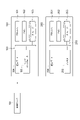
- FIG. 4 is a block diagram illustrating functional configurations of the local device 300 and the communication device 400.
- the communication device 400 has a receiving section 411 and a receiving buffer 412 as functional blocks.
- the receiver 411 sequentially receives a plurality of command data sets from the transmitter 211 .
- the receiving unit 411 may receive the command data set from the transmitting unit 211 through network communication, may receive the command data set from the transmitting unit 211 through wireless communication, or may receive the command data set from the transmitting unit 211 through mobile communication. may be received.
- the receiving unit 411 stores the plurality of command data sets in the receiving buffer 412 in the order in which they were received.
- the order in which the receiving unit 411 receives the multiple command data sets may differ from the order in which the transmitting unit 211 transmits the multiple command data sets.
- the local device 300 has a clock 311, an arrangement section 312, a standby buffer 313, a reading section 314, and a local controller 315 as functional blocks.
- a clock 311 repeatedly generates time at a constant cycle.
- the time generated by the clock 311 will be referred to as "local time”.
- the clock 311 may be configured to generate a local time synchronized with the global time.
- the clock 311 receives the server time from the control server 100 through communication such as TSN communication that guarantees time synchronization, and generates the local time in synchronization with the received server time.
- the clock 311 synchronizes the local time with the server time and then repeatedly updates the local time by counting clock pulses for a fixed cycle.
- the clock 311 may repeatedly synchronize the local time with the server time at predetermined time intervals.
- the standby buffer 313 is a storage unit for temporarily storing a plurality of command data sets in order based on order information.
- the arranging unit 312 arranges the plurality of command data sets received by the receiving unit 411 in the waiting buffer 313 in the order based on the order information. For example, the arrangement unit 312 reads out a plurality of command data sets from the reception buffer 412 using the FIFO method. For example, the arrangement unit 312 reads the plurality of command data sets stored in the reception buffer 412 from the reception buffer 412 in the order in which they were stored.
- the arrangement unit 312 arranges the plurality of command data sets read from the reception buffer 412 in the standby buffer 313 in the order based on the order information. For example, the arranging unit 312 arranges the data in the standby buffer 313 in the above-described predetermined order based on the order information. For example, when order information whose value increases as it is arranged later is added to each of the plurality of command data sets, the arranging unit 312 waits for the plurality of command data sets so that they are arranged in ascending order of the value of the order information. Arrange in buffer 313 . When order information whose value becomes smaller as it goes later in the order is added to each of the plurality of command data sets, the arranging unit 312 arranges the plurality of command data sets in order of increasing value of the order information. be arranged in
- the arranging unit 312 arranges the plurality of command data sets in the standby buffer 313 in the order of read timing based on the timing information. You may let
- the arranging unit 312 arranges the plurality of command data sets in the standby buffer 313 so that they are arranged in the order of the read time. good too.
- the arranging unit 312 may arrange the plurality of command data sets in the standby buffer 313 so that they are arranged in the order of the generation time.
- the arranging unit 312 may arrange the plurality of command data sets in the standby buffer 313 so that they are arranged in the order of the added time. .
- FIG. 5 is a schematic diagram illustrating the storage contents of the reception buffer 412 and the storage contents of the standby buffer 313.
- FIG. The numerical value shown in parentheses of each command data set represents the generation time.
- transmission of a plurality of command data sets by the transmission unit 211 is performed in order of generation time.
- the order of transmission of the plurality of command data sets and the order of reception of the plurality of command data sets may change, the order of the plurality of command data sets in the reception buffer 412 is not necessarily the order of generation time.
- a plurality of command data sets that are not arranged in order of generation time in the reception buffer 412 are rearranged in order of generation time in the waiting buffer 313 by the arranging section 312 .
- the reading unit 314 sequentially reads the plurality of command data sets stored in the standby buffer 313 in the order in which they are arranged.
- the reading unit 314 may repeat reading the command data set from the standby buffer 313 in a constant reading cycle. For example, the reading unit 314 reads the head data set located at the head of the arrangement in the standby buffer 313 among the plurality of command data sets each time a periodic read clock signal is generated.
- the reading unit 314 may read each of the plurality of command data sets at the reading timing specified by the timing information. For example, the reading unit 314 may read the leading data set when the reading time specified by the timing information of the leading data set is included in the execution period of the reading cycle.
- the leading data set whose read time specified by the timing information is included in the execution period of the read cycle is referred to as "read target data set”.
- cycle length of the read cycle and the cycle length of the control cycle are the same, there will be one data set to be read in each read cycle unless the instruction data set is missing. Reading of the command data set from 313 will be repeated in the read cycle.
- the reading unit 314 may read each of the plurality of command data sets at a reading timing after a predetermined delay time has elapsed from the reference timing.
- the arranging unit 312 may convert the reference timing included in the timing information into the read timing when storing each of the plurality of command data sets in the standby buffer 313 .
- the arrangement unit 312 may calculate the readout time by adding the delay time to the generation time or the addition time of the timing information, and include the calculated readout time in the timing information.
- the reading unit 314 reads the head data set when the reading time included in the order information by the arranging unit 312 is included in the execution period of the reading cycle.
- the arrangement unit 312 may convert the readout time specified by the timing information into the number of readout cycles from the time of storage in the standby buffer 313 (the time of storing the command data set in the standby buffer 313) to the readout time. For example, the arranging unit 312 may calculate the number of waiting cycles by dividing the time from the time of storing in the waiting buffer 313 to the time of reading by the reading cycle, and include the calculated number of waiting cycles in the timing information.
- the readout unit 314 repeatedly counts down the number of standby cycles of each of the plurality of command data sets arranged in the standby buffer 313 in read cycles, and reads the top data set whose number of standby cycles is zero from the standby buffer 313 .
- the number of waiting cycles being zero means that the read time is included in the execution period of the read cycle. Therefore, the head data set with the number of waiting cycles of zero is the read target data set.
- the local controller 315 operates the corresponding machine 30 based on the plurality of command data sets read by the reading unit 314 . For example, the local controller 315 causes the machine 30 to perform an action corresponding to the target action represented by the command data set each time the reading unit 314 reads the command data set. As a result, the control of the machine 30 is repeated in the local control cycle having the same cycle length as the read stop cycle. If the target motion includes a target position, local controller 315 repeats the local control cycle to cause machine 30 to follow the target position. If the target motion repeats the target speed, the local controller 315 causes the operating speed of the machine 30 to follow the target speed in repeated local control cycles.
- the local device 300 may further have a delay setting section 321 .
- the delay setting unit 321 sets the delay time for converting the reference timing into the read timing based on the input to the user interface.
- the local device 300 may further include a data confirmation section 322, a stop section 323, and a retransmission request section 324. Based on the arrangement of the plurality of command data sets in the standby buffer 313 and the timing information, the data confirmation unit 322 detects missing command data sets to be read in the read cycle.
- the data checking unit 322 detects the missing command data set to be read before the leading data set. For example, if the read time specified by the timing information of the leading data set is not included in the execution period of the reading cycle for reading the leading data set, the data checking unit 322 detects the lack of command data sets to be read before the leading data set. to detect
- a read cycle for reading the leading data set is hereinafter referred to as a "leading read cycle”.
- the lack of the command data set to be read before the leading data set is called “missing data set to be read”.
- the cycle length of the read cycle and the cycle length of the control cycle match, there is one data set to be read for each read cycle as long as no command data set is missing. Therefore, each read cycle becomes a "head read cycle”.
- the data confirmation unit 322 may detect lack of the read target data set when the number of waiting cycles of the leading data set is not zero.
- the data confirmation unit 322 may confirm whether or not the timing information of the leading data set corresponds to the leading read cycle after the leading reading cycle is started or before the leading reading cycle is started. .
- the reading unit 314 may wait to read the leading data set until the next reading cycle after the leading reading cycle.
- Missing command data set the lack of a command data set that should be placed between two command data sets.
- the stopping unit 323 stops the driving unit (for example, the actuators 71, 72, 73, 74, 75 of the machine 30) when the number of read cycles in which the lack of the command data set is continuously detected reaches a predetermined number of times of driving stop. , 76, the automatic guided vehicle 31, the automatic guided vehicle 33, etc.) are stopped.
- the stopping unit 323 stops communication between the transmitting unit 211 and the receiving unit 411 when the number of read cycles in which the lack of the command data set is continuously detected reaches a predetermined number of communication stops that is greater than the number of drive stops. may be stopped.
- the stopping unit 323 may stop the driving unit when the number of leading read cycles in which the missing data set to be read is continuously detected equals the number of drive stops.
- the stopping unit 323 may stop communication between the transmitting unit 211 and the receiving unit 411 when the number of lead read cycles in which the lack of the read target data set is continuously detected becomes the communication stop count.
- the stopping unit 323 may stop the driving unit when missing command data sets corresponding to the number of drive stop times are detected between the two command data sets.
- the stopping unit 323 may stop the communication between the transmitting unit 211 and the receiving unit 411 when missing command data sets corresponding to the number of communication stops are detected between the two command data sets.
- the resend request section 324 requests the transmission section 211 to resend the command data set in which the missing is detected. For example, when the data confirmation unit 322 detects the missing command data set, the retransmission request unit 324 may request the transmission unit 211 to retransmit the command data set in which the missing command data set is detected. The retransmission request unit 324 may request the transmitting unit 211 to retransmit the read target data set when missing of the read target data set is detected.
- the retransmission request unit 324 may cause the reception unit 411 to request the transmission unit 211 to retransmit the command data set.
- Transmitting section 211 may be configured to hold the transmitted command data set in preparation for a retransmission request from retransmission requesting section 324 .
- the arranging unit 312 may cause the receiving unit 411 to transmit an acknowledgment signal of the command data set to the transmitting unit 211 when the command data set is stored in the standby buffer 313 .
- the transmitter 211 may hold the command data set until it receives the acknowledge signal.
- the local controller 315 may be configured to sequentially obtain, from the machine 30, multiple feedback data sets including operational results based on multiple command data sets. Local controller 315 may repeatedly obtain feedback data sets in the local control cycle. For example, local controller 315 may obtain a feedback data set each time it operates machine 30 based on a command data set in the local control cycle.
- the controller 111 may be configured to generate the command data set based on the feedback data set obtained by the local controller 315 .
- the controller 111 may generate a command data set representing a target output (eg, a target torque or a target current) for causing the operation of the machine 30 represented by the feedback data set to follow the target operation.
- the controller 111 performs a proportional operation, a proportional/integral operation, or a proportional/integral/differential operation on the deviation between the target operation and the operation of the machine 30 represented by the feedback data set to generate the command data set representing the target output.
- the communication system 1 adds second order information to each of the plurality of feedback data sets acquired by the local controller 315, and sequentially transmits the plurality of feedback data sets to which the second order information is added. and Sequentially receiving the transmitted multiple feedback data sets, arranging the received multiple feedback data sets in the second waiting buffer in the order based on the second order information, and and sequentially reading the plurality of feedback data sets in an arranged order.
- local controller 315 is the supplying application and controller 111 is the consuming application.
- the local device 300 may further have a second information addition section 331 .
- the second information adding section 331 adds second order information to each of the plurality of feedback data sets acquired by the local controller 315 .
- the second information addition unit 331 adds the second order information and sends it to the communication device 400 .
- the second information addition unit 331 stores the feedback data set with the second order information added in the second transmission buffer 422 of the communication device 400 .
- the second order information is information for determining the order in which multiple feedback data sets are arranged.
- the second order information has a value and determines the position (order) of each feedback data set in the above order based on comparison with other second order information values.
- the second information adding unit 331 adds second order information having a larger value toward each of the plurality of feedback data sets so that the plurality of feedback data sets are arranged in a predetermined order.
- the second information adding section 331 may add second order information including a count value from the top in the order of arrangement to each of the plurality of feedback data sets.
- the second information adding section 331 may add second order information whose value becomes smaller as it goes later in the order of arrangement to each of the plurality of feedback data sets.
- the second information adding section 331 may add second order information including a count value from the tail in the order of arrangement to each of the plurality of feedback data sets.
- the second information addition unit 331 may add second order information to each of the plurality of feedback data sets so that the order of the plurality of feedback data sets is the order of acquisition by the local controller 315 .
- the second information adding unit 331 adds the second order information whose value increases as it gets later in the order of acquisition by the local controller 315 to each of the plurality of feedback data sets.
- the second information addition unit 331 adds order information including the local time at the time of acquisition to each of the plurality of feedback data sets.
- acquisition time the local time at the time of acquisition
- the second information adding section 331 may add the second order information including the local time immediately before adding the second order information to each of the plurality of feedback data sets.
- second addition time the local time immediately before adding the second order information
- the second information addition unit 331 may add a count value that is incremented every time the local controller 315 acquires the feedback data set as the second order information to the feedback data set.
- the second information addition unit 331 may add second order information including second timing information that determines the read timing of the feedback data set by the control server 100 to each of the plurality of feedback data sets.
- the second timing information may be time information that directly specifies the read timing of the feedback data set by the control server 100 (hereinafter referred to as “second read timing”).
- second read timing time information that directly specifies the read timing of the feedback data set by the control server 100
- the second information addition unit 331 adds a predetermined second delay time to the acquisition time or the second addition time to calculate a second readout time representing the second readout timing, and calculates a second readout time including the calculated second readout time. 2. Order information is added to each of the multiple feedback data sets.
- the second timing information may be time information that indirectly specifies the timing at which the control server 100 should read the feedback data set.
- the second timing information may be information representing a second reference timing before the transmission timing of the feedback data set by the communication device 400 (second transmission section 421 described later). If the second delay time from the second reference timing to the second readout timing is constant, the second readout timing is indirectly determined by the acquisition time or the second additional time. Examples of information representing the second reference timing include the acquisition time or the second addition time.
- the second information addition unit 331 adds identification information and second order information of the corresponding machines 30 and sends them to the communication device 400 . Based on the identification information of the machine 30, the feedback data set can be obtained by the controller 111 corresponding to the machine 30.
- the communication device 400 may further include a second transmission section 421 and a second transmission buffer 422.
- the second transmission buffer 422 is a storage unit for temporarily storing a plurality of feedback data sets added with the second order information and sent from the second information adding unit 331 .
- the second transmission unit 421 sequentially reads the plurality of feedback data sets to which the second order information is added from the second transmission buffer 422 .
- the second transmission unit 421 may read multiple feedback data sets from the second transmission buffer 422 in the FIFO method. For example, the second transmission unit 421 sequentially reads the plurality of feedback data sets stored in the second transmission buffer 422 from the second transmission buffer 422 in the order in which they were stored.
- the second transmission unit 421 transmits the feedback data set read from the second transmission buffer 422 to the communication device 200 .
- the second transmitter 421 may transmit the feedback data set through network communication, may transmit the feedback data set through wireless communication, or may transmit the feedback data set through mobile communication.
- the communication device 200 further includes a second receiving section 221 and a second receiving buffer 222.
- the second receiver 221 sequentially receives a plurality of feedback data sets from the second transmitter 421 .
- the second receiving unit 221 may receive the feedback data set from the second transmitting unit 421 through network communication, may receive the feedback data set from the second transmitting unit 421 through wireless communication, or may receive the feedback data set through mobile communication. 2 may receive a feedback data set from the transmitter 421 .
- the second receiving unit 221 stores the plurality of feedback data sets in the second receiving buffer 222 in the order in which they were received.
- the order in which the second receiver 221 receives the multiple feedback data sets may differ from the order in which the second transmitter 421 transmits the multiple feedback data sets.
- the second receiving unit 221 may add identification information of the local controller 315 that acquired the feedback data set to the feedback data set and store the feedback data set in the second reception buffer 222. . This enables each of the plurality of controllers 111 to acquire the plurality of feedback data sets acquired by the corresponding local controller 315 .
- the control server 100 further has a second arrangement section 121 , a second standby buffer 122 and a second reading section 123 .
- the second standby buffer 122 is a storage unit for temporarily storing a plurality of feedback data sets in order based on the second order information.
- the second arranging section 121 arranges the plurality of feedback data sets received by the second receiving section 221 in the second standby buffer 122 in the order based on the second order information. For example, the second arrangement unit 121 reads multiple feedback data sets from the second reception buffer 222 in a FIFO manner. For example, the second arrangement unit 121 reads the plurality of feedback data sets stored in the second reception buffer 222 from the second reception buffer 222 in the order in which they were stored.
- the second arrangement unit 121 arranges the plurality of feedback data sets read from the second reception buffer 222 in the second standby buffer 122 in the order based on the second order information. For example, the second arranging unit 121 arranges in the second waiting buffer 122 in the above-described predetermined order based on the second order information. For example, when the second order information whose value increases as it is arranged later is added to each of the plurality of feedback data sets, the second arrangement unit 121 arranges the plurality of feedback data sets so that the value of the second order information is arranged in ascending order. of feedback data sets are arranged in the second waiting buffer 122 .
- the second arrangement unit 121 arranges the plurality of feedback data so that the value of the second order information is arranged in descending order. Arrange the data set in the second waiting buffer 122 .
- the second arrangement unit 121 sorts the plurality of feedback data sets into the second order information based on the second timing information. They may be arranged in the second standby buffer 122 in order of read timing.
- the second arrangement unit 121 arranges the plurality of feedback data sets in order of the second readout time. may be arranged in the second waiting buffer 122 .
- the second arranging unit 121 arranges the plurality of feedback data sets in the second standby buffer 122 so as to be arranged in the order of acquisition time. can be arranged in
- the second arrangement unit 121 arranges the plurality of feedback data sets in the order of the second addition time. 2 waiting buffer 122 .
- the second reading unit 123 sequentially reads the plurality of feedback data sets stored in the second standby buffer 122 in the order in which they are arranged.
- the second reading unit 123 may repeat reading the command data set from the second standby buffer 122 in a constant second reading cycle. For example, the second reading unit 123 reads the top data set located at the top of the arrangement in the second standby buffer 122 among the plurality of feedback data sets each time the periodic second read clock signal is generated.
- the second reading unit 123 removes the read head data set from the array in the second standby buffer 122 .
- the second reading unit 123 may read each of the plurality of feedback data sets at the second reading timing specified by the second timing information. For example, the second reading unit 123 may read the leading data set when the second reading time specified by the second timing information of the feedback data set is included in the execution period of the second reading cycle.
- the head data set whose second read time specified by the second timing information is included in the execution period of the second read cycle is referred to as "read target data set”.
- the second reading unit 123 may read each of the plurality of feedback data sets at a second reading timing after a predetermined second delay time has elapsed from the second reference timing.
- the second arrangement unit 121 may convert the second reference timing included in the second timing information into the second read timing when storing each of the plurality of feedback data sets in the second standby buffer 122.
- the second arrangement unit 121 calculates the second readout time by adding the second delay time to the acquisition time or the second addition time of the second timing information, and includes the calculated second readout time in the second timing information.
- the second reading unit 123 reads the leading data set when the second reading time included in the second order information by the second arranging unit 121 is included in the execution period of the second reading cycle.
- the second arrangement unit 121 arranges the second read time specified by the second timing information from the time of storage in the second standby buffer 122 (the time of storing the feedback data set in the second standby buffer 122) to the second read time. may be converted into the number of second read cycles. For example, the second array unit 121 calculates the second standby cycle number by dividing the time from the storage time in the second standby buffer 122 to the second readout time by the second readout cycle, and calculates the calculated second standby cycle number. may be included in the second timing information.
- the second reading unit 123 repeatedly counts down the second waiting cycle number of each of the plurality of feedback data sets arranged in the second waiting buffer 122 in the second reading cycle, and reads the leading data whose second waiting cycle number is zero. Read the set from the second wait buffer 122 .
- the fact that the second wait cycle number is zero means that the second read time is included in the execution period of the second read cycle. Therefore, the head data set whose second wait cycle number is zero is the read target data set.
- the controller 111 generates command data sets based on the feedback data sets read by the second reading unit 123 .
- the control server 100 may have multiple second array units 121 , multiple second standby buffers 122 , and multiple second read units 123 .
- the plurality of second array units 121 correspond to the plurality of controllers 111
- the plurality of second standby buffers 122 respectively correspond to the plurality of second array units 121
- the plurality of second reading units 123 correspond to the plurality of second array units 121, respectively. 2 waiting buffers 122, respectively.
- Each of the plurality of second arrangement units 121 reads the feedback data from the corresponding local controller 315 from the second reception buffer 222 based on the identification information of the local controller 315 added to the feedback data set, Send to waiting buffer 122 .
- multiple feedback data sets acquired by the corresponding local controller 315 are stored in each of the multiple second standby buffers 122 .
- the control server 100 may further have a second delay setting unit 131.
- a second delay setting unit 131 sets a second delay time for converting the second reference timing to the second read timing based on an input to the user interface.
- the control server 100 may further include a second data confirmation section 132, a second stop section 133, and a second retransmission request section .
- the control server 100 may further have a plurality of sets of second data confirmation section 132, second stop section 133, and second retransmission request section 134 corresponding to the plurality of controllers 111 respectively. good.
- the second data confirmation unit 132 detects missing feedback data sets to be read in the second read cycle based on the arrangement of the plurality of feedback data sets in the second standby buffer 122 and the second timing information.
- the second data checking unit 132 detects the lack of the feedback data set to be read before the leading data set. . For example, if the second read time specified by the second timing information of the leading data set is not included in the execution period of the second reading cycle for reading the leading data set, the second data checking unit 132 determines whether the second data set is read before the leading data set. Detect missing feedback data set to be read out.
- a read cycle for reading the leading data set is hereinafter referred to as a "leading read cycle”.
- the missing of the feedback data set to be read before the leading data set is referred to as "missing of the read target data set”.
- the cycle length of the second read cycle and the cycle length of the local control cycle match, there is one data set to be read for each second read cycle unless a feedback data set is missing. do. Therefore, each second read cycle becomes a "head read cycle".
- the second data confirmation unit 132 may detect lack of the read target data set when the second waiting cycle number of the leading data set is not zero.
- the second data confirmation unit 132 may confirm whether or not the second timing information of the head data set corresponds to the head read cycle after the head read cycle starts, or may confirm before the head read cycle starts. good too.
- the second reading unit 123 may wait until the second reading cycle following the leading reading cycle before reading the leading data set when missing of the reading target data set is detected.
- the second data confirmation unit 132 determines that the difference between the two feedback data sets adjacent to each other in the arrangement of the second standby buffer 122 is equal to or greater than twice the second read cycle. Missing feedback data sets that should be placed between feedback data sets may be detected. Hereinafter, the lack of a feedback data set that should be placed between two feedback data sets is referred to as "missing feedback data set”.
- the second stopping unit 133 stops the driving unit (for example, the actuators 71 and 72 of the machine 30) when the number of second read cycles in which the lack of the feedback data set is continuously detected reaches a predetermined number of second driving stops. , 73, 74, 75, 76, the automatic guided vehicle 31, and the automatic guided vehicle 33, etc.).
- the driving unit for example, the actuators 71 and 72 of the machine 30
- 73, 74, 75, 76 the automatic guided vehicle 31, and the automatic guided vehicle 33, etc.
- the second stopping unit 133 may cause the controller 111 to output a command to stop the driving unit when the number of leading read cycles in which the lack of the data set to be read is detected reaches the second drive stop count.
- the second stopping unit 133 stops the communication between the second receiving unit 221 and the second transmitting unit 421 when the number of leading read cycles in which the lack of the data set to be read is continuously detected reaches the second communication stop count. Communication may be stopped.
- the second stopping unit 133 may cause the controller 111 to output a command to stop the driving unit when a missing feedback data set corresponding to the second number of drive stops is detected between the two feedback data sets.
- the second stopping unit 133 suspends communication between the second receiving unit 221 and the second transmitting unit 421 when a missing feedback data set corresponding to the second communication stop count is detected between the two feedback data sets. You can stop it.
- the second retransmission request unit 134 requests the second transmission unit 421 to retransmit the missing feedback data set. For example, when the second data confirmation unit 132 detects the missing feedback data set, the second retransmission request unit 134 requests the second transmission unit 421 to retransmit the feedback data set in which the missing feedback data set is detected. good. The second retransmission request unit 134 may request the second transmission unit 421 to retransmit the read target data set when missing of the read target data set is detected.
- the second retransmission request unit 134 may cause the second reception unit 221 to request the second transmission unit 421 to retransmit the feedback data set.
- the second transmission section 421 may be configured to hold the transmitted feedback data set in preparation for the retransmission request of the second retransmission request section 134 .
- the second arrangement section 121 may cause the second receiving section 221 to transmit an acknowledgment signal of the feedback data set to the second transmitting section 421 .
- the second transmitter 421 may hold the feedback data set until it receives the acknowledge signal.
- FIG. 9 is a block diagram illustrating the hardware configuration of the control server 100 and the communication device 200. As shown in FIG. As shown in FIG. 9, the control server 100 has circuitry 190 . Circuit 190 has processor 191 , memory 192 , storage 193 , communication port 194 and user interface 195 .
- the storage 193 is a non-volatile storage medium. Specific examples of the storage 193 include a hard disk, flash memory, and the like. The storage 193 may be a portable storage medium such as an optical disc.
- the storage 193 stores a program for causing the control server 100 to control the machine 30 and add the order information to each of a plurality of command data sets to be sent to the communication device 200 . For example, the storage 193 stores a program for causing the control server 100 to configure each functional block described above.
- the memory 192 is a temporary storage medium such as random access memory, and temporarily stores programs loaded from the storage 193 .
- the processor 191 is composed of one or more arithmetic elements, and executes a program loaded in the memory 192 to cause the control server 100 to configure each of the above functional blocks.
- the communication port 194 communicates with the time server 101 and the communication device 200 in response to requests from the processor 191 .
- the user interface 195 is a device for performing input by the user and presenting information to the user, and includes, for example, an input device and a display device.
- input devices include keyboards, mice, keypads, and the like.
- display devices include liquid crystal monitors and organic EL (Electro-Luminescence) monitors.
- the input device may be integrated with the display device as a so-called touch panel.
- the communication device 200 has a circuit 290.
- Circuit 290 has processor 291 , memory 292 , storage 293 and communication port 294 .
- the storage 293 is a non-volatile storage medium. Specific examples of the storage 193 include a hard disk, flash memory, and the like. The storage 193 may be a portable storage medium such as an optical disc. The storage 293 stores programs for configuring the functional blocks described above in the communication device 200 .
- the memory 292 is a temporary storage medium such as random access memory, and temporarily stores programs loaded from the storage 293 .
- the processor 291 is composed of one or more arithmetic elements, and executes a program loaded in the memory 292 to cause the communication device 200 to configure each of the functional blocks described above.
- Communication port 294 communicates with communication port 194 in response to requests from processor 291 .
- Antenna 295 transmits and receives a signal for wireless communication according to a request from processor 291 .
- FIG. 10 is a block diagram illustrating the hardware configuration of the local device 300 and the communication device 400.
- local device 300 has circuitry 390 .
- Circuitry 390 includes processor 391 , memory 392 , storage 393 , communication port 394 and drive circuitry 395 .
- the storage 393 is a non-volatile storage medium. Specific examples of the storage 393 include a hard disk, flash memory, and the like.
- the storage 393 may be a portable storage medium such as an optical disc.
- the storage 393 arranges the plurality of command data sets acquired from the communication device 400 in the waiting buffer in the order based on the order information, and sequentially reads out the plurality of command data sets stored in the waiting buffer in the arranged order. and operating the machine 30 based on the read command data set.
- the storage 393 stores a program for causing the local device 300 to configure each functional block described above.
- the memory 392 is a temporary storage medium such as random access memory, and temporarily stores programs loaded from the storage 393 .
- the processor 391 is composed of one or more arithmetic elements, and executes a program loaded in the memory 392 to configure the above functional blocks in the local device 300 .
- Communication port 394 communicates with communication device 400 in response to requests from processor 391 .
- the drive circuit 395 outputs drive power to the machine 30 and acquires feedback data sets from the machine 30 in response to requests from the processor 391 .
- the user interface 396 is a device for inputting by the user and presenting information to the user, and includes, for example, an input device and a display device.
- input devices include keyboards, mice, keypads, and the like.
- display devices include liquid crystal monitors and organic EL (Electro-Luminescence) monitors.
- the input device may be integrated with the display device as a so-called touch panel.
- the communication device 400 has a circuit 490.
- Circuit 490 has processor 491 , memory 492 , storage 493 and communication port 494 .
- the storage 493 is a non-volatile storage medium. Specific examples of the storage 493 include a hard disk, flash memory, and the like.
- the storage 193 may be a portable storage medium such as an optical disc.
- Storage 493 stores a program for configuring each functional block described above in communication device 400 .
- the memory 492 is a temporary storage medium such as random access memory, and temporarily stores programs loaded from the storage 493 .
- the processor 491 is composed of one or more arithmetic elements, and executes a program loaded in the memory 492 to make the communication device 400 configure each of the above functional blocks.
- Communication port 494 communicates with communication port 494 in response to requests from processor 491 .
- Antenna 495 transmits and receives a signal for wireless communication according to a request from processor 491 .
- the communication system 1 may comprise multiple hardware devices each including multiple controllers 111 .
- an information adding unit 113, a second arranging unit 121, a second standby buffer 122, a second reading unit 123, a second delay setting unit 131, and a second data checking unit, which constitute a part of the communication system 1 132 , the second stop unit 133 and the second retransmission request unit 134 may be incorporated in the communication device 200 .
- the adding unit 331 may be incorporated in the communication device 400 .
- the communication device 200 may be incorporated in the control server 100 and the communication device 400 may be incorporated in the local device 300 .
- This control procedure consists of sequentially generating a plurality of command data sets, adding order information to each of the plurality of command data sets, and sequentially transmitting the plurality of command data sets to which the order information is added. and sequentially receive the plurality of transmitted command data sets; arrange the received plurality of command data sets in the standby buffer 313 in the order based on the order information; and sequentially reading the command data sets in sequenced order.
- the above control procedure will be described below as a command data set generation and transmission procedure executed by the control server 100, a plurality of feedback data set arrangement procedures executed by the control server 100, a communication procedure executed by the communication device 200, and a local control procedure.
- a local control procedure executed by the device 300, a procedure for arranging a plurality of command data sets executed by the local device 300, and a communication procedure executed by the communication device 400 are illustrated separately.
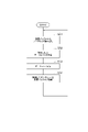
- FIG. 11 is a flow chart illustrating a procedure for generating and transmitting a command data set.
- the flowchart of FIG. 11 is executed while the plurality of feedback data sets are stored in the second standby buffer 122 in the order based on the second order information.
- the second order information of each of the plurality of feedback data sets includes second timing information converted into a second read cycle number from the time of storage in the second standby buffer 122 to the second read time.
- the control server 100 first executes steps S01 and S02.
- step S ⁇ b>01 the second reading unit 123 counts down the number of second reading cycles by one for each of the plurality of feedback data sets in the second standby buffer 122 .
- step S ⁇ b>02 the second reading unit 123 checks whether or not there is a data set to be read in the second standby buffer 122 . For example, the second reading unit 123 confirms whether or not the number of second read cycles of the leading data set in the second standby buffer 122 is zero.
- step S02 When it is determined in step S02 that there is a data set to be read, the control server 100 executes steps S03, S04, S05, and S06.
- step S ⁇ b>03 the second reading unit 123 reads the head data set (feedback data set) from the second standby buffer 122 .
- step S ⁇ b>04 the controller 111 generates a command data set based on the first data set read by the second standby buffer 122 .
- step S ⁇ b>05 the information addition unit 113 adds order information to the command data set generated by the controller 111 .
- step S ⁇ b>06 the information addition unit 113 stores the command data set with the order information added in the transmission buffer 212 .
- step S07 the second data confirmation unit 132 confirms whether or not there is a missing feedback data set in the second standby buffer 122 . If it is determined in step S07 that the feedback data set is missing, the control server 100 executes step S08. In step S08, second retransmission requesting section 134 requests second transmitting section 421 to retransmit the feedback data set in which the missing is detected.
- step S09 the second reading unit 123 waits for the second reading cycle to elapse. After that, the control server 100 returns the process to step S01.
- step S12 the second stopping unit 133 confirms whether or not the number of leading read cycles in which the lack of the data set to be read is continuously detected is the second driving stop count.
- the number of leading read cycles in which the missing data set to be read is continuously detected will be referred to as the “continuous missing count”.
- step S12 If it is determined in step S12 that the number of times of continuous missing is the number of times of stopping the second drive, the control server 100 executes step S13.
- step S ⁇ b>13 the second stopping unit 133 causes the controller 111 to output a command to stop the operation of the machine 30 .
- step S14 the control server 100 executes step S14. If it is determined in step S12 that the number of consecutive dropouts is not the number of times of the second drive stop, the control server 100 executes step S14 without executing step S13.
- step S14 the second stopping unit 133 confirms whether or not the number of times of consecutive omissions is the second number of times of communication stopping. If it is determined in step S14 that the number of consecutive omissions is not the number of second communication stoppages, the control server 100 advances the process to step S09. Thereafter, after waiting for the read cycle to elapse, the process returns to step S01. Therefore, reading of the head data set is delayed until the next read cycle.
- step S14 when it is determined that the number of consecutive omissions is the number of second communication stoppages, the control server 100 executes step S15.
- step S ⁇ b>15 the second stopping section 133 stops communication between the second receiving section 221 and the second transmitting section 421 . This completes the command data set generation and transmission procedure.
- step S ⁇ b>21 the arrangement unit 312 waits for one or more instruction data sets to be stored in the reception buffer 412 .
- step S22 the arrangement unit 312 reads out the command data sets from the reception buffer 412 in the order in which they were stored.
- step S23 the arranging unit 312 converts the read timing information of the command data set into the number of read cycles from the storage time in the standby buffer 313 to the read time.
- step S24 the arranging unit 312 arranges the command data sets obtained by converting the timing information into the number of read cycles in the standby buffer 313 in the order of the read timings determined by the timing information (in descending order of the number of read cycles).
- step S25 the arranging unit 312 checks whether or not there are any unread command data sets left in the receiving buffer 412. If it is determined in step S25 that the command data set that has not been read remains in the reception buffer 412, the local device 300 returns the process to step S22. Thereafter, reading of the command data set and arrangement in the standby buffer 313 are repeated until reading of the command data set from the reception buffer 412 is completed. If it is determined in step S25 that no unread command data set remains in the reception buffer 412, the local device 300 returns the process to step S21. The local device 300 repeatedly executes the above processing.
- step S31 the transmission unit 211 reads out the command data sets from the transmission buffer 212 in the order in which they were stored.
- step S ⁇ b>32 the transmission unit 211 transmits the read instruction data set to the reception unit 411 .
- step S ⁇ b>33 the second receiver 221 receives the feedback data set transmitted from the second transmitter 421 .
- step S ⁇ b>34 the second receiver 221 stores the received feedback data set in the second transmission buffer 422 .
- FIG. 14 is a flow chart illustrating the local control procedure.
- the flowchart of FIG. 14 is executed while a plurality of command data sets are stored in the standby buffer 313 in the order based on the order information.
- the order information for each of the plurality of command data sets includes timing information converted into the number of read cycles from the time of storage in the standby buffer 313 to the time of readout.
- the local device 300 first executes steps S41 and S42.
- step S ⁇ b>41 the reading unit 314 counts down the number of read cycles by one for each of the plurality of command data sets in the standby buffer 313 .
- step S ⁇ b>42 the reading unit 314 checks whether or not there is a data set to be read in the standby buffer 313 . For example, the reading unit 314 confirms whether or not the number of read cycles of the leading data set in the standby buffer 313 is zero.
- step S42 If it is determined in step S42 that there is a data set to be read, the local device 300 executes steps S43 and S44.
- step S ⁇ b>43 the reading unit 314 reads the head data set (command data set) from the standby buffer 313 .
- step S44 the local controller 315 confirms whether or not the command data set read by the standby buffer 313 is a stop command.
- step S44 If it is determined in step S44 that the command data set is not a stop command, the local device 300 executes steps S45, S46, and S47.
- step S ⁇ b>45 the local controller 315 operates the machine 30 based on the command data set read by the reading unit 314 and obtains a feedback data set representing the operation result of the machine 30 .
- step S ⁇ b>46 the second information adding section 331 adds second order information to the feedback data set acquired by the local controller 315 .
- step S ⁇ b>47 the second information addition unit 331 stores the feedback data set with the second order information added in the second transmission buffer 422 .
- step S51 the local device 300 executes step S51.
- step S ⁇ b>51 the data confirmation unit 322 confirms whether or not there is a missing command data set in the standby buffer 313 . If it is determined in step S22 that the instruction data set is missing, the local device 300 executes step S52.
- step S52 the retransmission request unit 324 requests the transmission unit 211 to retransmit the instruction data set in which the omission is detected.
- step S53 the local device 300 executes step S53.
- step S51 the local device 300 executes step S51 without executing step S52.
- step S53 the second reading unit 123 waits for the reading cycle to elapse. After that, the control server 100 returns the process to step S41.
- step S42 When it is determined in step S42 that there is no data set to be read, the local device 300 executes steps S61 and S62.
- step S61 the data confirmation unit 322 detects missing of the read target data set and notifies the occurrence of the missing. For example, the data confirmation unit 322 notifies the occurrence of omission by displaying on the display device of the user interface 396 or the like.
- step S62 the stopping unit 323 confirms whether or not the number of leading read cycles in which the lack of the data set to be read is continuously detected is the drive stop count.
- the number of leading read cycles in which the missing data set to be read is continuously detected will be referred to as the “continuous missing count”.
- step S62 If it is determined in step S62 that the number of times of continuous missing is the number of times of stopping driving, the local device 300 executes step S63. Also when it determines with a command data set being a stop command in step S44, the local device 300 performs step S63. In step S ⁇ b>63 , the stopping unit 323 causes the local controller 315 to stop the operation of the machine 30 .
- step S64 when it determines with the frequency
- step S64 the stopping unit 323 confirms whether or not the number of consecutive missing times is equal to the number of communication stop times.
- step S64 when it determines with the frequency
- step S65 If it is determined in step S64 that the number of consecutive omissions is the number of communication stoppages, the local device 300 executes step S65. In step S ⁇ b>65 , the stopping unit 323 stops communication between the transmitting unit 211 and the receiving unit 411 . This completes the local control procedure.
- step S ⁇ b>71 the second arrangement unit 121 waits for one or more feedback data sets to be stored in the second reception buffer 222 .
- step S72 the second arrangement unit 121 reads out the feedback data sets from the second reception buffer 222 in the order in which they were stored.
- step S ⁇ b>73 the second arrangement unit 121 converts the timing information of the read feedback data set into a second read cycle number from the storage time in the second standby buffer 122 to the second read time.
- step S74 the second array unit 121 arranges the feedback data set obtained by converting the timing information into the second read cycle number in the order of the second read timings determined by the timing information (in descending order of the second read cycle number). Arrange them in the waiting buffer 122 .
- step S75 the second arrangement unit 121 confirms whether or not any unread feedback data set remains in the second reception buffer 222. If it is determined in step S75 that the feedback data set that has not been read remains in the second reception buffer 222, the control server 100 returns the process to step S72. After that, the reading of the feedback data set and the arrangement in the second standby buffer 122 are repeated until the reading of the feedback data set from the second reception buffer 222 is completed. If it is determined in step S75 that no unread feedback data set remains in the second reception buffer 222, the control server 100 returns the process to step S71. The control server 100 repeatedly executes the above processing.
- step S81 the second transmission unit 421 reads out the feedback data sets from the second transmission buffer 422 in the order in which they were stored.
- step S ⁇ b>82 the second transmitter 421 transmits the read feedback data set to the second receiver 221 .
- step S ⁇ b>83 the receiving section 411 receives the instruction data set transmitted from the transmitting section 211 .
- step S ⁇ b>84 the receiving unit 411 stores the received instruction data set in the receiving buffer 412 .
- the communication system 1 includes the information addition unit 113 that adds order information to each of a plurality of data sets, the transmission unit 211 that sequentially transmits the plurality of data sets to which the order information is added, A receiving unit 411 that sequentially receives a plurality of data sets from the transmitting unit 211; and a reading unit 314 that sequentially reads out the plurality of stored data sets in the order in which they are arranged.
- the order of sending multiple data sets and the order of receiving multiple data sets may change. For example, an earlier transmitted data set may be received later than a later transmitted data set. Even if the order of transmission and the order of reception are reversed, according to the communication system 1, a plurality of data sets can be sequentially read in the order based on the order information. Therefore, regardless of the order of reception, the order of use of a plurality of data sets can be controlled by the order information. Therefore, the communication system 1 is effective in using a plurality of data sets received through communication in proper order.
- the order information may include timing information that determines read timing, and the reading unit 314 may read each of the plurality of data sets at the read timing specified by the timing information. Read timing can be appropriately controlled based on the timing information.
- the arranging unit 312 may arrange the plurality of data sets in the standby buffer 313 in order of read timing based on the timing information included in the order information. Since both the arrangement by the arrangement unit 312 and the readout timing by the readout unit 314 are controlled by the timing information, the information added to the data set can be reduced.
- the timing information is information representing the reference timing before the transmission timing by the transmission unit 211, and the reading unit 314 may read each of the plurality of data sets at the reading timing after a predetermined delay time has elapsed from the reference timing. By adjusting the delay time, the read timing can be easily adjusted.
- a delay setting unit 321 that sets the delay time based on an input to the user interface may be further provided. In this case, the read timing can be easily changed according to the application of the communication system 1 .
- the reading unit 314 repeats reading data sets from the standby buffer 313 in a constant reading cycle, and the communication system 1 reads the data sets in the reading cycle based on the arrangement of the plurality of data sets in the standby buffer 313 and the timing information.
- a data confirmation unit 322 that detects missing data sets may be further provided. Missing data sets can be easily detected based on the relationship between the read cycle and the timing information.
- the plurality of data sets includes data sets used to control drives (e.g., actuators 71, 72, 73, 74, 75, 76 of machine 30, AGV 31, AGV 33, etc.), and the communication system 1 may further include a stopping unit 323 for stopping the driving unit when the number of read cycles in which missing data sets are continuously detected reaches a predetermined number of driving stops. Unexpected operation of the driving unit due to unstable communication can be avoided.
- the stopping unit 323 stops communication between the transmitting unit and the receiving unit when the number of read cycles in which the lack of data sets is continuously detected reaches a predetermined number of times of communication stop, which is greater than the number of times of stopping the drive. good too. In this case, it is possible to avoid excessive continuation of unstable communication while maintaining communication even after the driving unit is stopped.
- the data confirmation unit 322 detects the missing data set to be read before the head data set. may be detected. Missing data sets can be detected more easily.
- the reading unit 314 may wait to read the leading data set until the next reading cycle after the reading cycle in which the leading data set is to be read, when the lack of the data set to be read before the leading data set is detected. . Order information-based ordering can be used to easily handle missing data sets.
- a retransmission request unit 324 may be further provided that requests the transmission unit 211 to retransmit the data set when the data confirmation unit 322 detects that the data set is missing. Missing datasets can be suppressed.
- the transmission section 211 may hold the transmitted data set in preparation for the retransmission request of the retransmission request section 324 . Missing data sets can be further suppressed.
- the receiving unit 411 stores the plurality of data sets in the receiving buffer 412 in the order in which they were received, and the arranging unit 312 reads out the plurality of data sets stored in the receiving buffer 412 from the receiving buffer 412 in the order in which they were stored, and arranges the data sets in the order. They may be arranged in the waiting buffer 313 in order based on the information. It is possible to simplify the configuration of the reception buffer 412 on the premise that the order of arrangement is arranged by the arrangement unit 312 .
- the transmission unit 211 may transmit the data set through network communication, and the reception unit 411 may receive the data set from the transmission unit 211 through network communication. According to network communication, the order is likely to be changed. Therefore, it is more effective to control the order of use of a plurality of data sets by means of order information regardless of the order of reception.
- the transmitting unit 211 may transmit the data set by wireless communication, and the receiving unit 411 may receive the data set from the transmitting unit 211 by wireless communication. Therefore, it is more effective to control the order of use of a plurality of data sets by means of order information regardless of the order of reception.
- the transmitting unit 211 may transmit the dataset via mobile communication, and the receiving unit 411 may receive the dataset from the transmitting unit 211 via mobile communication. According to mobile communication, the order is likely to be changed. Therefore, it is more effective to control the order of use of a plurality of data sets by means of order information regardless of the order of reception.
- the control system 10 includes the communication system 1, a controller 111 that sequentially generates a plurality of command data sets, and a local controller 315 that operates the machine based on the plurality of command data sets.
- 111 adds order information to each of the plurality of command data sets generated
- the transmitting unit 211 sequentially transmits the plurality of command data sets to which the order information is added
- the receiving unit 411 transmits the plurality of command data sets.
- the arranging unit 312 arranges the plurality of command data sets received by the receiving unit 411 in the order based on the order information in the standby buffer 313, and the reading unit 314 receives the plurality of command data sets stored in the waiting buffer 313.
- the data sets are sequentially read out in the order in which they are arranged, and the local controller 315 operates the machine based on the plurality of command data sets read by the reading unit 314 .
- the communication system 1 can be effectively used for synchronous communication in machine control.
- the local controller 315 sequentially acquires a plurality of feedback data sets including operation results based on a plurality of instruction data sets, and the communication system 1 adds second order information to each of the plurality of feedback data sets acquired by the local controller 315.
- a second information addition unit 331 to add;
- a second transmission unit 421 for sequentially transmitting a plurality of feedback data sets to which the second order information is added;
- a second receiving unit 221, a second arranging unit 121 that arranges the plurality of feedback data sets received by the second receiving unit 221 in the second waiting buffer 122 in an order based on the second order information, and a second waiting buffer 122
- a second reading unit 123 that sequentially reads out the plurality of stored feedback data sets in the order in which they are arranged may be further provided.
- the communication system 1 can be used more effectively for machine control.
- the controller 111 may generate the command data set based on the feedback data set read by the second reading unit 123 .
- the communication system 1 can be effectively used for constructing a feedback loop in machine control.
- Reference Signs List 1 communication system 10 control system 300 local device 211 transmission unit 212 transmission buffer 411 reception unit 412 reception buffer 111 controller 113 information addition unit 312 arrangement unit 313... Standby buffer 314... Reading unit 321... Delay setting unit 322... Data confirmation unit 323... Stop unit 324... Retransmission request unit 421... Second transmission unit 422... Second transmission buffer 221... Second 2 receiving units 222 second receiving buffer 331 second information adding unit 121 second arrangement unit 122 second waiting buffer 123 second reading unit 131 second delay setting unit 132 Second data confirmation section, 133... Second stop section, 134... Second retransmission request section.
Landscapes
- Engineering & Computer Science (AREA)
- General Engineering & Computer Science (AREA)
- Manufacturing & Machinery (AREA)
- Quality & Reliability (AREA)
- Physics & Mathematics (AREA)
- General Physics & Mathematics (AREA)
- Automation & Control Theory (AREA)
- Computer Security & Cryptography (AREA)
- Computer Networks & Wireless Communication (AREA)
- Signal Processing (AREA)
- Computer And Data Communications (AREA)
- Mobile Radio Communication Systems (AREA)
Priority Applications (3)
| Application Number | Priority Date | Filing Date | Title |
|---|---|---|---|
| JP2023533066A JP7650977B2 (ja) | 2021-07-07 | 2022-02-25 | 通信システム、コントロールシステム、及び通信方法 |
| CN202280047236.3A CN117597898A (zh) | 2021-07-07 | 2022-02-25 | 通信系统、控制系统以及通信方法 |
| US18/396,700 US20240142954A1 (en) | 2021-07-07 | 2023-12-27 | Communication system with ordered command data sets |
Applications Claiming Priority (2)
| Application Number | Priority Date | Filing Date | Title |
|---|---|---|---|
| US202163218928P | 2021-07-07 | 2021-07-07 | |
| US63/218,928 | 2021-07-07 |
Related Child Applications (1)
| Application Number | Title | Priority Date | Filing Date |
|---|---|---|---|
| US18/396,700 Continuation US20240142954A1 (en) | 2021-07-07 | 2023-12-27 | Communication system with ordered command data sets |
Publications (1)
| Publication Number | Publication Date |
|---|---|
| WO2023281805A1 true WO2023281805A1 (ja) | 2023-01-12 |
Family
ID=84801527
Family Applications (1)
| Application Number | Title | Priority Date | Filing Date |
|---|---|---|---|
| PCT/JP2022/007885 Ceased WO2023281805A1 (ja) | 2021-07-07 | 2022-02-25 | 通信システム、コントロールシステム、及び通信方法 |
Country Status (4)
| Country | Link |
|---|---|
| US (1) | US20240142954A1 (https=) |
| JP (1) | JP7650977B2 (https=) |
| CN (1) | CN117597898A (https=) |
| WO (1) | WO2023281805A1 (https=) |
Citations (4)
| Publication number | Priority date | Publication date | Assignee | Title |
|---|---|---|---|---|
| JP2010167550A (ja) * | 2008-12-24 | 2010-08-05 | Daihen Corp | ロボット制御システム及びコントローラ |
| JP2011082708A (ja) * | 2009-10-05 | 2011-04-21 | Panasonic Electric Works Co Ltd | パケット挿入削除方法及び通話システム |
| WO2014010171A1 (ja) * | 2012-07-09 | 2014-01-16 | パナソニック株式会社 | 通信装置、通信方法、プログラム |
| JP2020145573A (ja) * | 2019-03-06 | 2020-09-10 | キヤノン株式会社 | 通信装置、通信方法及びプログラム |
Family Cites Families (9)
| Publication number | Priority date | Publication date | Assignee | Title |
|---|---|---|---|---|
| JP2002328886A (ja) * | 2001-04-27 | 2002-11-15 | Canon Inc | 遠隔操作システム、遠隔操作方法、被操作装置、操作端末、プログラムおよび記憶媒体 |
| JP3829804B2 (ja) * | 2003-01-20 | 2006-10-04 | 株式会社デンソー | 車両用遠隔制御システム |
| JP4929993B2 (ja) * | 2006-11-10 | 2012-05-09 | 横河電機株式会社 | 制御通信装置および制御通信方法 |
| JP5028316B2 (ja) * | 2008-04-02 | 2012-09-19 | アラクサラネットワークス株式会社 | セル分散型スイッチファブリック |
| JP5429003B2 (ja) * | 2010-03-30 | 2014-02-26 | 富士通株式会社 | 情報処理装置、通信制御方法及び通信制御プログラム |
| JP5787946B2 (ja) * | 2013-08-07 | 2015-09-30 | 三菱電機株式会社 | 通信装置、機器操作システム、通信方法及びプログラム |
| JP6262064B2 (ja) * | 2014-04-17 | 2018-01-17 | 日立アプライアンス株式会社 | 遠隔操作装置、遠隔操作システム |
| JP6456776B2 (ja) * | 2015-06-04 | 2019-01-23 | 日本電信電話株式会社 | 遅延揺らぎ吸収方法 |
| CN112596933B (zh) * | 2021-02-26 | 2021-05-14 | 全时云商务服务股份有限公司 | 一种基于消息事件通信的微服务系统 |
-
2022
- 2022-02-25 CN CN202280047236.3A patent/CN117597898A/zh active Pending
- 2022-02-25 WO PCT/JP2022/007885 patent/WO2023281805A1/ja not_active Ceased
- 2022-02-25 JP JP2023533066A patent/JP7650977B2/ja active Active
-
2023
- 2023-12-27 US US18/396,700 patent/US20240142954A1/en active Pending
Patent Citations (4)
| Publication number | Priority date | Publication date | Assignee | Title |
|---|---|---|---|---|
| JP2010167550A (ja) * | 2008-12-24 | 2010-08-05 | Daihen Corp | ロボット制御システム及びコントローラ |
| JP2011082708A (ja) * | 2009-10-05 | 2011-04-21 | Panasonic Electric Works Co Ltd | パケット挿入削除方法及び通話システム |
| WO2014010171A1 (ja) * | 2012-07-09 | 2014-01-16 | パナソニック株式会社 | 通信装置、通信方法、プログラム |
| JP2020145573A (ja) * | 2019-03-06 | 2020-09-10 | キヤノン株式会社 | 通信装置、通信方法及びプログラム |
Also Published As
| Publication number | Publication date |
|---|---|
| CN117597898A (zh) | 2024-02-23 |
| JP7650977B2 (ja) | 2025-03-25 |
| JPWO2023281805A1 (https=) | 2023-01-12 |
| US20240142954A1 (en) | 2024-05-02 |
Similar Documents
| Publication | Publication Date | Title |
|---|---|---|
| JP3751309B2 (ja) | ロボット制御装置 | |
| CN103370664B (zh) | 电动机控制系统及通信方法 | |
| US12030174B2 (en) | Machine control via wireless communication | |
| CN103009402B (zh) | 机械臂控制装置以及机械臂系统 | |
| JP2010105150A (ja) | ロボットコンポーネント管理装置及び方法 | |
| JP6502114B2 (ja) | 通信制御システム及び通信制御方法 | |
| JP2023505631A (ja) | ロボット制御システム用の構成可能性フレームワーク | |
| JP2017175420A (ja) | 通信制御システム及び通信制御方法 | |
| WO2023281805A1 (ja) | 通信システム、コントロールシステム、及び通信方法 | |
| JP4980292B2 (ja) | 異なる通信周期で複数のアンプと通信する数値制御システム | |
| JP7639187B2 (ja) | 通信システム、通信装置、及び通信方法 | |
| CN115194757B (zh) | 机器人控制系统、下位控制装置以及机器人控制方法 | |
| JP3421172B2 (ja) | ロボット制御装置の通信方法 | |
| JP7663702B2 (ja) | 通信システム、通信制御回路及び通信方法 | |
| JPWO2023281805A5 (https=) | ||
| US20240243894A1 (en) | Wireless communication of transmission data by attribute | |
| JP2004025428A (ja) | ロボット制御装置の通信方法およびロボット制御装置 | |
| US12403604B2 (en) | Machine control via synchronous communication | |
| WO2023058116A1 (ja) | 通信システム及び通信方法 | |
| JP2013066963A (ja) | ロボット制御装置、及びロボットシステム | |
| EP4138402A1 (en) | Machine control system, program, machine, system, and device | |
| JP4980112B2 (ja) | 搬送ロボットの制御方法 | |
| WO2023138536A1 (zh) | 电机控制系统、电机控制方法和电机驱动和转发装置 | |
| JP2026004738A (ja) | ロボットシステム、指令装置、および、方法 | |
| CN118696567A (zh) | 通信系统以及通信终端 |
Legal Events
| Date | Code | Title | Description |
|---|---|---|---|
| 121 | Ep: the epo has been informed by wipo that ep was designated in this application |
Ref document number: 22837227 Country of ref document: EP Kind code of ref document: A1 |
|
| WWE | Wipo information: entry into national phase |
Ref document number: 2023533066 Country of ref document: JP |
|
| WWE | Wipo information: entry into national phase |
Ref document number: 202280047236.3 Country of ref document: CN |
|
| NENP | Non-entry into the national phase |
Ref country code: DE |
|
| 122 | Ep: pct application non-entry in european phase |
Ref document number: 22837227 Country of ref document: EP Kind code of ref document: A1 |