WO2023277132A1 - ガス貯蔵容器、架台、及びガス貯蔵システム - Google Patents
ガス貯蔵容器、架台、及びガス貯蔵システム Download PDFInfo
- Publication number
- WO2023277132A1 WO2023277132A1 PCT/JP2022/026224 JP2022026224W WO2023277132A1 WO 2023277132 A1 WO2023277132 A1 WO 2023277132A1 JP 2022026224 W JP2022026224 W JP 2022026224W WO 2023277132 A1 WO2023277132 A1 WO 2023277132A1
- Authority
- WO
- WIPO (PCT)
- Prior art keywords
- gas storage
- gas
- storage container
- casing
- container according
- Prior art date
- Legal status (The legal status is an assumption and is not a legal conclusion. Google has not performed a legal analysis and makes no representation as to the accuracy of the status listed.)
- Ceased
Links
Images


Classifications
-
- F—MECHANICAL ENGINEERING; LIGHTING; HEATING; WEAPONS; BLASTING
- F17—STORING OR DISTRIBUTING GASES OR LIQUIDS
- F17C—VESSELS FOR CONTAINING OR STORING COMPRESSED, LIQUEFIED OR SOLIDIFIED GASES; FIXED-CAPACITY GAS-HOLDERS; FILLING VESSELS WITH, OR DISCHARGING FROM VESSELS, COMPRESSED, LIQUEFIED, OR SOLIDIFIED GASES
- F17C13/00—Details of vessels or of the filling or discharging of vessels
- F17C13/02—Special adaptations of indicating, measuring, or monitoring equipment
- F17C13/025—Special adaptations of indicating, measuring, or monitoring equipment having the pressure as the parameter
-
- G—PHYSICS
- G01—MEASURING; TESTING
- G01F—MEASURING VOLUME, VOLUME FLOW, MASS FLOW OR LIQUID LEVEL; METERING BY VOLUME
- G01F23/00—Indicating or measuring liquid level or level of fluent solid material, e.g. indicating in terms of volume or indicating by means of an alarm
- G01F23/22—Indicating or measuring liquid level or level of fluent solid material, e.g. indicating in terms of volume or indicating by means of an alarm by measuring physical variables, other than linear dimensions, pressure or weight, dependent on the level to be measured, e.g. by difference of heat transfer of steam or water
- G01F23/26—Indicating or measuring liquid level or level of fluent solid material, e.g. indicating in terms of volume or indicating by means of an alarm by measuring physical variables, other than linear dimensions, pressure or weight, dependent on the level to be measured, e.g. by difference of heat transfer of steam or water by measuring variations of capacity or inductance of capacitors or inductors arising from the presence of liquid or fluent solid material in the electric or electromagnetic fields
- G01F23/263—Indicating or measuring liquid level or level of fluent solid material, e.g. indicating in terms of volume or indicating by means of an alarm by measuring physical variables, other than linear dimensions, pressure or weight, dependent on the level to be measured, e.g. by difference of heat transfer of steam or water by measuring variations of capacity or inductance of capacitors or inductors arising from the presence of liquid or fluent solid material in the electric or electromagnetic fields by measuring variations in capacitance of capacitors
-
- F—MECHANICAL ENGINEERING; LIGHTING; HEATING; WEAPONS; BLASTING
- F17—STORING OR DISTRIBUTING GASES OR LIQUIDS
- F17C—VESSELS FOR CONTAINING OR STORING COMPRESSED, LIQUEFIED OR SOLIDIFIED GASES; FIXED-CAPACITY GAS-HOLDERS; FILLING VESSELS WITH, OR DISCHARGING FROM VESSELS, COMPRESSED, LIQUEFIED, OR SOLIDIFIED GASES
- F17C1/00—Pressure vessels, e.g. gas cylinder, gas tank, replaceable cartridge
-
- F—MECHANICAL ENGINEERING; LIGHTING; HEATING; WEAPONS; BLASTING
- F17—STORING OR DISTRIBUTING GASES OR LIQUIDS
- F17C—VESSELS FOR CONTAINING OR STORING COMPRESSED, LIQUEFIED OR SOLIDIFIED GASES; FIXED-CAPACITY GAS-HOLDERS; FILLING VESSELS WITH, OR DISCHARGING FROM VESSELS, COMPRESSED, LIQUEFIED, OR SOLIDIFIED GASES
- F17C11/00—Use of gas-solvents or gas-sorbents in vessels
-
- F—MECHANICAL ENGINEERING; LIGHTING; HEATING; WEAPONS; BLASTING
- F17—STORING OR DISTRIBUTING GASES OR LIQUIDS
- F17C—VESSELS FOR CONTAINING OR STORING COMPRESSED, LIQUEFIED OR SOLIDIFIED GASES; FIXED-CAPACITY GAS-HOLDERS; FILLING VESSELS WITH, OR DISCHARGING FROM VESSELS, COMPRESSED, LIQUEFIED, OR SOLIDIFIED GASES
- F17C13/00—Details of vessels or of the filling or discharging of vessels
- F17C13/02—Special adaptations of indicating, measuring, or monitoring equipment
- F17C13/021—Special adaptations of indicating, measuring, or monitoring equipment having the height as the parameter
-
- F—MECHANICAL ENGINEERING; LIGHTING; HEATING; WEAPONS; BLASTING
- F17—STORING OR DISTRIBUTING GASES OR LIQUIDS
- F17C—VESSELS FOR CONTAINING OR STORING COMPRESSED, LIQUEFIED OR SOLIDIFIED GASES; FIXED-CAPACITY GAS-HOLDERS; FILLING VESSELS WITH, OR DISCHARGING FROM VESSELS, COMPRESSED, LIQUEFIED, OR SOLIDIFIED GASES
- F17C13/00—Details of vessels or of the filling or discharging of vessels
- F17C13/02—Special adaptations of indicating, measuring, or monitoring equipment
- F17C13/026—Special adaptations of indicating, measuring, or monitoring equipment having the temperature as the parameter
-
- G—PHYSICS
- G01—MEASURING; TESTING
- G01F—MEASURING VOLUME, VOLUME FLOW, MASS FLOW OR LIQUID LEVEL; METERING BY VOLUME
- G01F23/00—Indicating or measuring liquid level or level of fluent solid material, e.g. indicating in terms of volume or indicating by means of an alarm
-
- G—PHYSICS
- G01—MEASURING; TESTING
- G01F—MEASURING VOLUME, VOLUME FLOW, MASS FLOW OR LIQUID LEVEL; METERING BY VOLUME
- G01F23/00—Indicating or measuring liquid level or level of fluent solid material, e.g. indicating in terms of volume or indicating by means of an alarm
- G01F23/30—Indicating or measuring liquid level or level of fluent solid material, e.g. indicating in terms of volume or indicating by means of an alarm by floats
-
- H—ELECTRICITY
- H02—GENERATION; CONVERSION OR DISTRIBUTION OF ELECTRIC POWER
- H02J—ELECTRIC POWER NETWORKS; CIRCUIT ARRANGEMENTS OR SYSTEMS FOR SUPPLYING OR DISTRIBUTING ELECTRIC POWER; SYSTEMS FOR STORING ELECTRIC ENERGY
- H02J50/00—Circuit arrangements or systems for wireless supply or distribution of electric power
- H02J50/005—Mechanical details of housing or structure aiming to accommodate the power transfer means, e.g. mechanical integration of coils, antennas or transducers into emitting or receiving devices
-
- H—ELECTRICITY
- H02—GENERATION; CONVERSION OR DISTRIBUTION OF ELECTRIC POWER
- H02J—ELECTRIC POWER NETWORKS; CIRCUIT ARRANGEMENTS OR SYSTEMS FOR SUPPLYING OR DISTRIBUTING ELECTRIC POWER; SYSTEMS FOR STORING ELECTRIC ENERGY
- H02J7/00—Circuit arrangements for charging or discharging batteries or for supplying loads from batteries
- H02J7/50—Circuit arrangements for charging or discharging batteries or for supplying loads from batteries acting upon multiple batteries simultaneously or sequentially
-
- H—ELECTRICITY
- H02—GENERATION; CONVERSION OR DISTRIBUTION OF ELECTRIC POWER
- H02J—ELECTRIC POWER NETWORKS; CIRCUIT ARRANGEMENTS OR SYSTEMS FOR SUPPLYING OR DISTRIBUTING ELECTRIC POWER; SYSTEMS FOR STORING ELECTRIC ENERGY
- H02J7/00—Circuit arrangements for charging or discharging batteries or for supplying loads from batteries
- H02J7/70—Circuit arrangements for charging or discharging batteries or for supplying loads from batteries characterised by the mechanical construction
-
- F—MECHANICAL ENGINEERING; LIGHTING; HEATING; WEAPONS; BLASTING
- F17—STORING OR DISTRIBUTING GASES OR LIQUIDS
- F17C—VESSELS FOR CONTAINING OR STORING COMPRESSED, LIQUEFIED OR SOLIDIFIED GASES; FIXED-CAPACITY GAS-HOLDERS; FILLING VESSELS WITH, OR DISCHARGING FROM VESSELS, COMPRESSED, LIQUEFIED, OR SOLIDIFIED GASES
- F17C2201/00—Vessel construction, in particular geometry, arrangement or size
- F17C2201/01—Shape
- F17C2201/0104—Shape cylindrical
- F17C2201/0109—Shape cylindrical with exteriorly curved end-piece
-
- F—MECHANICAL ENGINEERING; LIGHTING; HEATING; WEAPONS; BLASTING
- F17—STORING OR DISTRIBUTING GASES OR LIQUIDS
- F17C—VESSELS FOR CONTAINING OR STORING COMPRESSED, LIQUEFIED OR SOLIDIFIED GASES; FIXED-CAPACITY GAS-HOLDERS; FILLING VESSELS WITH, OR DISCHARGING FROM VESSELS, COMPRESSED, LIQUEFIED, OR SOLIDIFIED GASES
- F17C2201/00—Vessel construction, in particular geometry, arrangement or size
- F17C2201/03—Orientation
- F17C2201/035—Orientation with substantially horizontal main axis
-
- F—MECHANICAL ENGINEERING; LIGHTING; HEATING; WEAPONS; BLASTING
- F17—STORING OR DISTRIBUTING GASES OR LIQUIDS
- F17C—VESSELS FOR CONTAINING OR STORING COMPRESSED, LIQUEFIED OR SOLIDIFIED GASES; FIXED-CAPACITY GAS-HOLDERS; FILLING VESSELS WITH, OR DISCHARGING FROM VESSELS, COMPRESSED, LIQUEFIED, OR SOLIDIFIED GASES
- F17C2201/00—Vessel construction, in particular geometry, arrangement or size
- F17C2201/05—Size
- F17C2201/056—Small (<1 m3)
-
- F—MECHANICAL ENGINEERING; LIGHTING; HEATING; WEAPONS; BLASTING
- F17—STORING OR DISTRIBUTING GASES OR LIQUIDS
- F17C—VESSELS FOR CONTAINING OR STORING COMPRESSED, LIQUEFIED OR SOLIDIFIED GASES; FIXED-CAPACITY GAS-HOLDERS; FILLING VESSELS WITH, OR DISCHARGING FROM VESSELS, COMPRESSED, LIQUEFIED, OR SOLIDIFIED GASES
- F17C2201/00—Vessel construction, in particular geometry, arrangement or size
- F17C2201/05—Size
- F17C2201/058—Size portable (<30 l)
-
- F—MECHANICAL ENGINEERING; LIGHTING; HEATING; WEAPONS; BLASTING
- F17—STORING OR DISTRIBUTING GASES OR LIQUIDS
- F17C—VESSELS FOR CONTAINING OR STORING COMPRESSED, LIQUEFIED OR SOLIDIFIED GASES; FIXED-CAPACITY GAS-HOLDERS; FILLING VESSELS WITH, OR DISCHARGING FROM VESSELS, COMPRESSED, LIQUEFIED, OR SOLIDIFIED GASES
- F17C2203/00—Vessel construction, in particular walls or details thereof
- F17C2203/06—Materials for walls or layers thereof; Properties or structures of walls or their materials
- F17C2203/0634—Materials for walls or layers thereof
- F17C2203/0636—Metals
- F17C2203/0646—Aluminium
-
- F—MECHANICAL ENGINEERING; LIGHTING; HEATING; WEAPONS; BLASTING
- F17—STORING OR DISTRIBUTING GASES OR LIQUIDS
- F17C—VESSELS FOR CONTAINING OR STORING COMPRESSED, LIQUEFIED OR SOLIDIFIED GASES; FIXED-CAPACITY GAS-HOLDERS; FILLING VESSELS WITH, OR DISCHARGING FROM VESSELS, COMPRESSED, LIQUEFIED, OR SOLIDIFIED GASES
- F17C2203/00—Vessel construction, in particular walls or details thereof
- F17C2203/06—Materials for walls or layers thereof; Properties or structures of walls or their materials
- F17C2203/0634—Materials for walls or layers thereof
- F17C2203/0636—Metals
- F17C2203/0648—Alloys or compositions of metals
-
- F—MECHANICAL ENGINEERING; LIGHTING; HEATING; WEAPONS; BLASTING
- F17—STORING OR DISTRIBUTING GASES OR LIQUIDS
- F17C—VESSELS FOR CONTAINING OR STORING COMPRESSED, LIQUEFIED OR SOLIDIFIED GASES; FIXED-CAPACITY GAS-HOLDERS; FILLING VESSELS WITH, OR DISCHARGING FROM VESSELS, COMPRESSED, LIQUEFIED, OR SOLIDIFIED GASES
- F17C2203/00—Vessel construction, in particular walls or details thereof
- F17C2203/06—Materials for walls or layers thereof; Properties or structures of walls or their materials
- F17C2203/0634—Materials for walls or layers thereof
- F17C2203/0658—Synthetics
- F17C2203/0663—Synthetics in form of fibers or filaments
-
- F—MECHANICAL ENGINEERING; LIGHTING; HEATING; WEAPONS; BLASTING
- F17—STORING OR DISTRIBUTING GASES OR LIQUIDS
- F17C—VESSELS FOR CONTAINING OR STORING COMPRESSED, LIQUEFIED OR SOLIDIFIED GASES; FIXED-CAPACITY GAS-HOLDERS; FILLING VESSELS WITH, OR DISCHARGING FROM VESSELS, COMPRESSED, LIQUEFIED, OR SOLIDIFIED GASES
- F17C2205/00—Vessel construction, in particular mounting arrangements, attachments or identifications means
- F17C2205/01—Mounting arrangements
- F17C2205/0103—Exterior arrangements
- F17C2205/0111—Boxes
-
- F—MECHANICAL ENGINEERING; LIGHTING; HEATING; WEAPONS; BLASTING
- F17—STORING OR DISTRIBUTING GASES OR LIQUIDS
- F17C—VESSELS FOR CONTAINING OR STORING COMPRESSED, LIQUEFIED OR SOLIDIFIED GASES; FIXED-CAPACITY GAS-HOLDERS; FILLING VESSELS WITH, OR DISCHARGING FROM VESSELS, COMPRESSED, LIQUEFIED, OR SOLIDIFIED GASES
- F17C2205/00—Vessel construction, in particular mounting arrangements, attachments or identifications means
- F17C2205/01—Mounting arrangements
- F17C2205/0123—Mounting arrangements characterised by number of vessels
- F17C2205/0126—One vessel
-
- F—MECHANICAL ENGINEERING; LIGHTING; HEATING; WEAPONS; BLASTING
- F17—STORING OR DISTRIBUTING GASES OR LIQUIDS
- F17C—VESSELS FOR CONTAINING OR STORING COMPRESSED, LIQUEFIED OR SOLIDIFIED GASES; FIXED-CAPACITY GAS-HOLDERS; FILLING VESSELS WITH, OR DISCHARGING FROM VESSELS, COMPRESSED, LIQUEFIED, OR SOLIDIFIED GASES
- F17C2205/00—Vessel construction, in particular mounting arrangements, attachments or identifications means
- F17C2205/01—Mounting arrangements
- F17C2205/0123—Mounting arrangements characterised by number of vessels
- F17C2205/013—Two or more vessels
-
- F—MECHANICAL ENGINEERING; LIGHTING; HEATING; WEAPONS; BLASTING
- F17—STORING OR DISTRIBUTING GASES OR LIQUIDS
- F17C—VESSELS FOR CONTAINING OR STORING COMPRESSED, LIQUEFIED OR SOLIDIFIED GASES; FIXED-CAPACITY GAS-HOLDERS; FILLING VESSELS WITH, OR DISCHARGING FROM VESSELS, COMPRESSED, LIQUEFIED, OR SOLIDIFIED GASES
- F17C2205/00—Vessel construction, in particular mounting arrangements, attachments or identifications means
- F17C2205/01—Mounting arrangements
- F17C2205/0153—Details of mounting arrangements
- F17C2205/0157—Details of mounting arrangements for transport
- F17C2205/0165—Details of mounting arrangements for transport with handgrip
-
- F—MECHANICAL ENGINEERING; LIGHTING; HEATING; WEAPONS; BLASTING
- F17—STORING OR DISTRIBUTING GASES OR LIQUIDS
- F17C—VESSELS FOR CONTAINING OR STORING COMPRESSED, LIQUEFIED OR SOLIDIFIED GASES; FIXED-CAPACITY GAS-HOLDERS; FILLING VESSELS WITH, OR DISCHARGING FROM VESSELS, COMPRESSED, LIQUEFIED, OR SOLIDIFIED GASES
- F17C2205/00—Vessel construction, in particular mounting arrangements, attachments or identifications means
- F17C2205/01—Mounting arrangements
- F17C2205/0153—Details of mounting arrangements
- F17C2205/0169—Details of mounting arrangements stackable
-
- F—MECHANICAL ENGINEERING; LIGHTING; HEATING; WEAPONS; BLASTING
- F17—STORING OR DISTRIBUTING GASES OR LIQUIDS
- F17C—VESSELS FOR CONTAINING OR STORING COMPRESSED, LIQUEFIED OR SOLIDIFIED GASES; FIXED-CAPACITY GAS-HOLDERS; FILLING VESSELS WITH, OR DISCHARGING FROM VESSELS, COMPRESSED, LIQUEFIED, OR SOLIDIFIED GASES
- F17C2221/00—Handled fluid, in particular type of fluid
- F17C2221/01—Pure fluids
- F17C2221/011—Oxygen
-
- F—MECHANICAL ENGINEERING; LIGHTING; HEATING; WEAPONS; BLASTING
- F17—STORING OR DISTRIBUTING GASES OR LIQUIDS
- F17C—VESSELS FOR CONTAINING OR STORING COMPRESSED, LIQUEFIED OR SOLIDIFIED GASES; FIXED-CAPACITY GAS-HOLDERS; FILLING VESSELS WITH, OR DISCHARGING FROM VESSELS, COMPRESSED, LIQUEFIED, OR SOLIDIFIED GASES
- F17C2221/00—Handled fluid, in particular type of fluid
- F17C2221/01—Pure fluids
- F17C2221/012—Hydrogen
-
- F—MECHANICAL ENGINEERING; LIGHTING; HEATING; WEAPONS; BLASTING
- F17—STORING OR DISTRIBUTING GASES OR LIQUIDS
- F17C—VESSELS FOR CONTAINING OR STORING COMPRESSED, LIQUEFIED OR SOLIDIFIED GASES; FIXED-CAPACITY GAS-HOLDERS; FILLING VESSELS WITH, OR DISCHARGING FROM VESSELS, COMPRESSED, LIQUEFIED, OR SOLIDIFIED GASES
- F17C2221/00—Handled fluid, in particular type of fluid
- F17C2221/01—Pure fluids
- F17C2221/013—Carbon dioxide
-
- F—MECHANICAL ENGINEERING; LIGHTING; HEATING; WEAPONS; BLASTING
- F17—STORING OR DISTRIBUTING GASES OR LIQUIDS
- F17C—VESSELS FOR CONTAINING OR STORING COMPRESSED, LIQUEFIED OR SOLIDIFIED GASES; FIXED-CAPACITY GAS-HOLDERS; FILLING VESSELS WITH, OR DISCHARGING FROM VESSELS, COMPRESSED, LIQUEFIED, OR SOLIDIFIED GASES
- F17C2221/00—Handled fluid, in particular type of fluid
- F17C2221/01—Pure fluids
- F17C2221/014—Nitrogen
-
- F—MECHANICAL ENGINEERING; LIGHTING; HEATING; WEAPONS; BLASTING
- F17—STORING OR DISTRIBUTING GASES OR LIQUIDS
- F17C—VESSELS FOR CONTAINING OR STORING COMPRESSED, LIQUEFIED OR SOLIDIFIED GASES; FIXED-CAPACITY GAS-HOLDERS; FILLING VESSELS WITH, OR DISCHARGING FROM VESSELS, COMPRESSED, LIQUEFIED, OR SOLIDIFIED GASES
- F17C2221/00—Handled fluid, in particular type of fluid
- F17C2221/01—Pure fluids
- F17C2221/016—Noble gases (Ar, Kr, Xe)
- F17C2221/017—Helium
-
- F—MECHANICAL ENGINEERING; LIGHTING; HEATING; WEAPONS; BLASTING
- F17—STORING OR DISTRIBUTING GASES OR LIQUIDS
- F17C—VESSELS FOR CONTAINING OR STORING COMPRESSED, LIQUEFIED OR SOLIDIFIED GASES; FIXED-CAPACITY GAS-HOLDERS; FILLING VESSELS WITH, OR DISCHARGING FROM VESSELS, COMPRESSED, LIQUEFIED, OR SOLIDIFIED GASES
- F17C2221/00—Handled fluid, in particular type of fluid
- F17C2221/03—Mixtures
- F17C2221/031—Air
-
- F—MECHANICAL ENGINEERING; LIGHTING; HEATING; WEAPONS; BLASTING
- F17—STORING OR DISTRIBUTING GASES OR LIQUIDS
- F17C—VESSELS FOR CONTAINING OR STORING COMPRESSED, LIQUEFIED OR SOLIDIFIED GASES; FIXED-CAPACITY GAS-HOLDERS; FILLING VESSELS WITH, OR DISCHARGING FROM VESSELS, COMPRESSED, LIQUEFIED, OR SOLIDIFIED GASES
- F17C2221/00—Handled fluid, in particular type of fluid
- F17C2221/03—Mixtures
- F17C2221/032—Hydrocarbons
- F17C2221/033—Methane, e.g. natural gas, CNG, LNG, GNL, GNC, PLNG
-
- F—MECHANICAL ENGINEERING; LIGHTING; HEATING; WEAPONS; BLASTING
- F17—STORING OR DISTRIBUTING GASES OR LIQUIDS
- F17C—VESSELS FOR CONTAINING OR STORING COMPRESSED, LIQUEFIED OR SOLIDIFIED GASES; FIXED-CAPACITY GAS-HOLDERS; FILLING VESSELS WITH, OR DISCHARGING FROM VESSELS, COMPRESSED, LIQUEFIED, OR SOLIDIFIED GASES
- F17C2221/00—Handled fluid, in particular type of fluid
- F17C2221/03—Mixtures
- F17C2221/032—Hydrocarbons
- F17C2221/035—Propane butane, e.g. LPG, GPL
-
- F—MECHANICAL ENGINEERING; LIGHTING; HEATING; WEAPONS; BLASTING
- F17—STORING OR DISTRIBUTING GASES OR LIQUIDS
- F17C—VESSELS FOR CONTAINING OR STORING COMPRESSED, LIQUEFIED OR SOLIDIFIED GASES; FIXED-CAPACITY GAS-HOLDERS; FILLING VESSELS WITH, OR DISCHARGING FROM VESSELS, COMPRESSED, LIQUEFIED, OR SOLIDIFIED GASES
- F17C2223/00—Handled fluid before transfer, i.e. state of fluid when stored in the vessel or before transfer from the vessel
- F17C2223/01—Handled fluid before transfer, i.e. state of fluid when stored in the vessel or before transfer from the vessel characterised by the phase
- F17C2223/0107—Single phase
- F17C2223/0123—Single phase gaseous, e.g. CNG, GNC
-
- F—MECHANICAL ENGINEERING; LIGHTING; HEATING; WEAPONS; BLASTING
- F17—STORING OR DISTRIBUTING GASES OR LIQUIDS
- F17C—VESSELS FOR CONTAINING OR STORING COMPRESSED, LIQUEFIED OR SOLIDIFIED GASES; FIXED-CAPACITY GAS-HOLDERS; FILLING VESSELS WITH, OR DISCHARGING FROM VESSELS, COMPRESSED, LIQUEFIED, OR SOLIDIFIED GASES
- F17C2223/00—Handled fluid before transfer, i.e. state of fluid when stored in the vessel or before transfer from the vessel
- F17C2223/01—Handled fluid before transfer, i.e. state of fluid when stored in the vessel or before transfer from the vessel characterised by the phase
- F17C2223/0146—Two-phase
- F17C2223/0153—Liquefied gas, e.g. LPG, GPL
- F17C2223/0161—Liquefied gas, e.g. LPG, GPL cryogenic, e.g. LNG, GNL, PLNG
-
- F—MECHANICAL ENGINEERING; LIGHTING; HEATING; WEAPONS; BLASTING
- F17—STORING OR DISTRIBUTING GASES OR LIQUIDS
- F17C—VESSELS FOR CONTAINING OR STORING COMPRESSED, LIQUEFIED OR SOLIDIFIED GASES; FIXED-CAPACITY GAS-HOLDERS; FILLING VESSELS WITH, OR DISCHARGING FROM VESSELS, COMPRESSED, LIQUEFIED, OR SOLIDIFIED GASES
- F17C2223/00—Handled fluid before transfer, i.e. state of fluid when stored in the vessel or before transfer from the vessel
- F17C2223/03—Handled fluid before transfer, i.e. state of fluid when stored in the vessel or before transfer from the vessel characterised by the pressure level
- F17C2223/033—Small pressure, e.g. for liquefied gas
-
- F—MECHANICAL ENGINEERING; LIGHTING; HEATING; WEAPONS; BLASTING
- F17—STORING OR DISTRIBUTING GASES OR LIQUIDS
- F17C—VESSELS FOR CONTAINING OR STORING COMPRESSED, LIQUEFIED OR SOLIDIFIED GASES; FIXED-CAPACITY GAS-HOLDERS; FILLING VESSELS WITH, OR DISCHARGING FROM VESSELS, COMPRESSED, LIQUEFIED, OR SOLIDIFIED GASES
- F17C2223/00—Handled fluid before transfer, i.e. state of fluid when stored in the vessel or before transfer from the vessel
- F17C2223/03—Handled fluid before transfer, i.e. state of fluid when stored in the vessel or before transfer from the vessel characterised by the pressure level
- F17C2223/036—Very high pressure (>80 bar)
-
- F—MECHANICAL ENGINEERING; LIGHTING; HEATING; WEAPONS; BLASTING
- F17—STORING OR DISTRIBUTING GASES OR LIQUIDS
- F17C—VESSELS FOR CONTAINING OR STORING COMPRESSED, LIQUEFIED OR SOLIDIFIED GASES; FIXED-CAPACITY GAS-HOLDERS; FILLING VESSELS WITH, OR DISCHARGING FROM VESSELS, COMPRESSED, LIQUEFIED, OR SOLIDIFIED GASES
- F17C2250/00—Accessories; Control means; Indicating, measuring or monitoring of parameters
- F17C2250/03—Control means
- F17C2250/034—Control means using wireless transmissions
-
- F—MECHANICAL ENGINEERING; LIGHTING; HEATING; WEAPONS; BLASTING
- F17—STORING OR DISTRIBUTING GASES OR LIQUIDS
- F17C—VESSELS FOR CONTAINING OR STORING COMPRESSED, LIQUEFIED OR SOLIDIFIED GASES; FIXED-CAPACITY GAS-HOLDERS; FILLING VESSELS WITH, OR DISCHARGING FROM VESSELS, COMPRESSED, LIQUEFIED, OR SOLIDIFIED GASES
- F17C2250/00—Accessories; Control means; Indicating, measuring or monitoring of parameters
- F17C2250/04—Indicating or measuring of parameters as input values
- F17C2250/0404—Parameters indicated or measured
- F17C2250/0408—Level of content in the vessel
-
- F—MECHANICAL ENGINEERING; LIGHTING; HEATING; WEAPONS; BLASTING
- F17—STORING OR DISTRIBUTING GASES OR LIQUIDS
- F17C—VESSELS FOR CONTAINING OR STORING COMPRESSED, LIQUEFIED OR SOLIDIFIED GASES; FIXED-CAPACITY GAS-HOLDERS; FILLING VESSELS WITH, OR DISCHARGING FROM VESSELS, COMPRESSED, LIQUEFIED, OR SOLIDIFIED GASES
- F17C2250/00—Accessories; Control means; Indicating, measuring or monitoring of parameters
- F17C2250/04—Indicating or measuring of parameters as input values
- F17C2250/0404—Parameters indicated or measured
- F17C2250/0421—Mass or weight of the content of the vessel
-
- F—MECHANICAL ENGINEERING; LIGHTING; HEATING; WEAPONS; BLASTING
- F17—STORING OR DISTRIBUTING GASES OR LIQUIDS
- F17C—VESSELS FOR CONTAINING OR STORING COMPRESSED, LIQUEFIED OR SOLIDIFIED GASES; FIXED-CAPACITY GAS-HOLDERS; FILLING VESSELS WITH, OR DISCHARGING FROM VESSELS, COMPRESSED, LIQUEFIED, OR SOLIDIFIED GASES
- F17C2250/00—Accessories; Control means; Indicating, measuring or monitoring of parameters
- F17C2250/04—Indicating or measuring of parameters as input values
- F17C2250/0404—Parameters indicated or measured
- F17C2250/043—Pressure
-
- F—MECHANICAL ENGINEERING; LIGHTING; HEATING; WEAPONS; BLASTING
- F17—STORING OR DISTRIBUTING GASES OR LIQUIDS
- F17C—VESSELS FOR CONTAINING OR STORING COMPRESSED, LIQUEFIED OR SOLIDIFIED GASES; FIXED-CAPACITY GAS-HOLDERS; FILLING VESSELS WITH, OR DISCHARGING FROM VESSELS, COMPRESSED, LIQUEFIED, OR SOLIDIFIED GASES
- F17C2250/00—Accessories; Control means; Indicating, measuring or monitoring of parameters
- F17C2250/04—Indicating or measuring of parameters as input values
- F17C2250/0404—Parameters indicated or measured
- F17C2250/0439—Temperature
-
- F—MECHANICAL ENGINEERING; LIGHTING; HEATING; WEAPONS; BLASTING
- F17—STORING OR DISTRIBUTING GASES OR LIQUIDS
- F17C—VESSELS FOR CONTAINING OR STORING COMPRESSED, LIQUEFIED OR SOLIDIFIED GASES; FIXED-CAPACITY GAS-HOLDERS; FILLING VESSELS WITH, OR DISCHARGING FROM VESSELS, COMPRESSED, LIQUEFIED, OR SOLIDIFIED GASES
- F17C2250/00—Accessories; Control means; Indicating, measuring or monitoring of parameters
- F17C2250/04—Indicating or measuring of parameters as input values
- F17C2250/0404—Parameters indicated or measured
- F17C2250/0482—Acceleration
-
- F—MECHANICAL ENGINEERING; LIGHTING; HEATING; WEAPONS; BLASTING
- F17—STORING OR DISTRIBUTING GASES OR LIQUIDS
- F17C—VESSELS FOR CONTAINING OR STORING COMPRESSED, LIQUEFIED OR SOLIDIFIED GASES; FIXED-CAPACITY GAS-HOLDERS; FILLING VESSELS WITH, OR DISCHARGING FROM VESSELS, COMPRESSED, LIQUEFIED, OR SOLIDIFIED GASES
- F17C2260/00—Purposes of gas storage and gas handling
- F17C2260/01—Improving mechanical properties or manufacturing
- F17C2260/012—Reducing weight
-
- H—ELECTRICITY
- H02—GENERATION; CONVERSION OR DISTRIBUTION OF ELECTRIC POWER
- H02J—ELECTRIC POWER NETWORKS; CIRCUIT ARRANGEMENTS OR SYSTEMS FOR SUPPLYING OR DISTRIBUTING ELECTRIC POWER; SYSTEMS FOR STORING ELECTRIC ENERGY
- H02J50/00—Circuit arrangements or systems for wireless supply or distribution of electric power
- H02J50/10—Circuit arrangements or systems for wireless supply or distribution of electric power using inductive coupling
- H02J50/12—Circuit arrangements or systems for wireless supply or distribution of electric power using inductive coupling of the resonant type
-
- H—ELECTRICITY
- H02—GENERATION; CONVERSION OR DISTRIBUTION OF ELECTRIC POWER
- H02J—ELECTRIC POWER NETWORKS; CIRCUIT ARRANGEMENTS OR SYSTEMS FOR SUPPLYING OR DISTRIBUTING ELECTRIC POWER; SYSTEMS FOR STORING ELECTRIC ENERGY
- H02J7/00—Circuit arrangements for charging or discharging batteries or for supplying loads from batteries
- H02J7/80—Circuit arrangements for charging or discharging batteries or for supplying loads from batteries including monitoring or indicating arrangements
- H02J7/82—Control of state of charge [SOC]
- H02J7/825—Detection of fully charged condition
Definitions
- the present disclosure relates to a gas storage container capable of contactless power supply.
- the present disclosure also relates to a mount for contactlessly powering a gas storage vessel.
- the present disclosure relates to gas storage systems comprising these gas storage vessels and mounts.
- Patent Document 1 discloses, as one variation thereof, a gas storage container comprising a casing having a flat upper surface and a lower surface, which can be stacked vertically, and a gas container installed in the casing (claim Item 9). This document also discloses a configuration further provided with a remaining amount of gas measuring module (claim 10).
- the electrical life of the remaining gas gauging module is generally shorter than the physical life of the gas container and casing.
- the electrical life of the remaining gas measuring module may be exhausted while the gas still remains in the gas container. Therefore, in the conventional configuration, when the electrical life of the remaining amount of gas measuring module expires, the gas storage container is once collected from the user regardless of the state of the gas container and casing or the remaining amount of gas. , it was necessary to take measures to charge or replace the remaining gas amount measurement module.
- an object of the present invention is to provide a configuration in which a user can supply power to a remaining gas amount measuring module in a gas storage container.
- the following gas storage container, pedestal, and gas storage system are provided.
- the remaining gas amount measurement module includes at least one sensor selected from the group consisting of a pressure sensor, a liquid level sensor, a temperature sensor, and a gyro sensor. gas storage container.
- the gas storage container according to [9] wherein the side surface provided with the hole has a recess for preventing the discharge port from protruding from the outer surface of the casing.
- the power receiving member is installed near another side surface opposite to the side surface provided with the hole.
- a base for non-contact power supply to the gas storage container according to any one of [1] to [17], the base for mounting the gas storage container, a bottom configured to contact a lower surface; a side for supporting the gas storage vessel, the side comprising at least one power transmitting section including a power transmitting member corresponding to the power receiving member.
- a trestle comprising a part and; [19] The pedestal according to [18], wherein the side portion is provided with a number of the power transmission units corresponding to the number of loaded gas storage containers.
- the gas storage container has a concave portion or a convex portion on the bottom surface, and the base has a convex portion or a concave portion corresponding to the concave portion or the convex portion on the bottom, [18] to [ 20].
- the casing of the gas storage container has a plurality of side surfaces, and further includes a grip portion on an outer edge between the lower surface and at least one of the side surfaces, and the pedestal includes the bottom portion and the The pedestal according to any one of [18] to [21], further comprising a fixing member for physically connecting with the grip part.
- the gas storage container further includes a battery that can be charged by the contactless power supply, and the power transmission unit further includes a lamp for indicating the charging state of the battery. [18] to [23] The pedestal according to any one of [23].
- the gas storage container it is possible to realize a configuration in which the user can supply power to the remaining gas amount measuring module.
- FIG. 1 is a perspective view of a gas storage container according to an embodiment of the present invention, viewed from above.
- FIG. 2 is a perspective view showing the state of the gas storage container according to one embodiment of the present invention as seen from the bottom side.
- FIG. 3 is a perspective view showing the state of the gas storage container according to one embodiment of the present invention as seen from the rear side.
- FIG. 4 is a conceptual diagram showing an example of the configuration of the remaining amount of gas measurement module.
- FIG. 5 is an exploded view showing a state in which a part of the casing and the gas container are removed in the gas storage container according to one embodiment of the present invention.
- FIG. 5 shows an example of a specific method of arranging the remaining amount of gas measurement module.
- FIG. 6 is a perspective view of a cradle and gas storage system according to one embodiment of the present invention.
- FIG. 7 is a perspective view and an exploded view of a gantry and gas storage system according to another embodiment of the invention.
- FIG. 8 is a conceptual diagram showing an example of the configuration of the power supply section of the pedestal according to one embodiment of the present invention.
- FIG. 9 is a perspective view showing an example of a gas storage system according to one embodiment of the invention.
- FIG. 10 is a front view showing an example of a gas storage system in which mounts according to one embodiment of the present invention are horizontally arranged.
- the gas storage container includes a casing that has flat upper and lower surfaces and can be stacked vertically, a gas container installed in the casing, and a power receiving member for contactless power supply. and a remaining amount of gas measurement module.
- FIG. 1 is a perspective view showing the state of the gas storage container according to one embodiment of the present invention as seen from the top side.
- FIG. 2 is a perspective view showing the state of the gas storage container according to one embodiment of the present invention as seen from the bottom side.
- FIG. 3 is a perspective view showing the state of the gas storage container according to one embodiment of the present invention as seen from the rear side.
- the gas storage container 10 shown in FIGS. 1 to 3 includes a casing 100, a gas container 200, and a remaining gas measuring module 300. As shown in FIG.
- the casing 100 has a substantially rectangular parallelepiped shape and includes an upper surface 110 , a lower surface 120 , a front surface 130 , a rear surface 140 , a right side 150 and a left side 160 . That is, the casing 100 has a top surface 110, a bottom surface 120, and four side surfaces 130-160.
- the notations such as “upper surface”, “lower surface”, “front”, “rear surface”, “right side”, “left side”, and “side” are only relative terms, and are used in actual use of the gas storage container 10. It does not limit the form. For example, it is possible to use the gas storage container 10 with the "front" facing up.
- the upper surface 110 and the lower surface 120 are substantially flat. This allows the casings 100 to be stacked vertically. By adopting such a configuration, transportation and installation of the gas storage container 10 become easy and efficient.
- the upper surface 110 includes a convex portion 110A.
- the lower surface 120 includes a concave portion 120A having a shape corresponding to the convex portion 110A.
- the concave portion 120A is configured to fit with the convex portion 110A. By adopting such a configuration, it becomes possible to stack the casings 100 in the vertical direction more stably.
- the convex portion 110A and the concave portion 120A may be omitted. It should be noted that when the convex portion and the concave portion are said to "fit”, it is not necessary for them to be physically fixed to each other, and it is sufficient that their shapes are spatially fitted to each other.
- the recess 120A is provided with a window 120B for making the gas container 200 visible from the outside.
- the label affixed on the gas container 200 can be viewed through the window 120B.
- the window 120B is typically transparent or translucent, preferably transparent, more preferably colorless and transparent.
- Window 120B may be hollow and may comprise a transparent or translucent member.
- the material of the transparent or translucent member that may be fitted in window 120B is, for example, plastic or glass, preferably plastic. If the window 120B is provided with a transparent or translucent member, it is possible to minimize the decrease in strength of the casing 100 due to the provision of the window 120B. Note that the window 120B may be omitted.
- the front face 130 is substantially flat and has holes 132 .
- the hole 132 has a role of exposing the outlet 202 of the gas container 200 to the outside.
- Holes 132 may be provided on a surface other than front surface 130 . Positioning the holes 132 on at least one side, rather than on the top 110 or bottom 120, allows the gas storage vessels 10 to be stacked one above the other even when the outlet 202 is fitted with valves and/or regulators.
- the front face 130 further comprises a recess 134 to prevent the outlet 202 from protruding from the outer surface of the casing 100.
- a valve is typically attached to the discharge port 202 .
- a regulator (not shown) is also typically attached to the valve when the gas storage container 10 is in use.
- a recess 134 in the front face 130 is typically configured so that the outlet 202 does not protrude beyond the outer surface of the casing 100 when the outlet 202 is valved but not regulated. ing.
- the recess 134 may be omitted.
- the rear surface 140 is substantially flat and faces the front surface 130 .
- a power receiving member of the remaining gas amount measuring module 300 is installed inside the casing 100 near the rear surface 140 of the gas storage container 10.
- a concave portion 142 is provided at a position corresponding to the power receiving member of the remaining amount of gas measurement module 300 on the back surface 140 .
- the configuration of the remaining amount of gas measurement module 300 will be described later in detail.
- the recess 142 may be omitted.
- the right side 150 is substantially flat.
- the right side surface 150 is provided with a convex portion 150A.
- the shape of the convex portion 150A is typically the same as the shape of the convex portion 110A.
- the convex portion 150A may be omitted.
- the left side 160 is substantially flat and faces the right side 150 .
- the left side surface 160 is provided with a recess 160A.
- the shape of recess 160A is typically identical to that of recess 120A, except that it does not include window 120B. That is, the concave portion 160A has a shape corresponding to the convex portion 150A. By adopting such a configuration, it is possible to efficiently arrange the casings 100 in the horizontal direction as well.
- the recess 160A may be omitted.
- the casing 100 has a first grip portion 170A on the outer edge between the upper surface 110 and the right side surface 150.
- Casing 100 also has a first gripping portion 170A on the outer edge between upper surface 110 and left side surface 160 .
- transportation of the gas storage container 10 becomes easier.
- FIGS. 1 to 3 when the holding portion is formed by forming a hollow portion in the outer edge portion, the weight of the gas storage container 10 can be further reduced.
- the first grip part 170A may be omitted.
- the casing 100 further has a second grip portion 170B on the outer edge between the lower surface 120 and the right side surface 150.
- the casing 100 further has a second grip portion 170B on the outer edge between the bottom surface 120 and the left side surface 160 as well.
- the casing 100 is configured so that it can be divided into two parts along a connecting surface 180 along the diagonal direction.
- one portion comprises a top surface 110, a right side surface 150, half of the front surface 130, and half of the rear surface 140.
- FIG. The other portion includes a bottom surface 120, a left side surface 160, the other half of the front surface 130, and the other half of the rear surface 140.
- FIG. These two parts are joined by screws (not shown) through screw holes 190 .
- the casing 100 can be prevented from being easily disassembled by the user by making the tool hole for the screw into a special shape.
- the connection surface 180 and screw hole 190 may be omitted.
- the joining of the parts constituting the casing 100 may be performed by other methods.
- the splittable configuration of the casing 100 makes it relatively easy for the operator of the gas storage container 10 to replace the casing 100 .
- the method of dividing the casing 100 is not limited.
- the material of the casing 100 is not particularly limited, and can be appropriately selected according to the required strength, desired weight, ease of molding, degree of electrical interference during contactless power supply, and the like.
- the material of casing 100 is, for example, plastic, fiber-reinforced plastic, metal, or alloy, preferably plastic or fiber-reinforced plastic.
- the casing 100 has a rectangular parallelepiped shape, but the shape of the casing 100 is not particularly limited as long as it satisfies the above requirements regarding the upper and lower surfaces.
- the casing 100 is, for example, cylindrical or prismatic, preferably quadrangular, pentagonal, or hexagonal, more preferably quadrangular or hexagonal.
- casing 100 preferably has a regular polygonal prism shape.
- the casing 100 is more preferably rectangular parallelepiped or cubic, particularly preferably rectangular parallelepiped.
- the plurality of side surfaces 130-160 are all substantially flat.
- a plurality of gas storage containers 10 can be arranged efficiently, so that the volume occupied during transport and use can be particularly reduced.
- the plurality of sides 130-160 need not be flat.
- front 130 and back 140 may be non-flat, while right 150 and left 160 sides may be substantially flat.
- the upper surface 110 has projections 110A and the lower surface 120 has recesses 120A corresponding to the projections 110A, but there is no particular limitation on the configuration of these projections and recesses.
- the top surface 110 may have a recess and the bottom surface may have a corresponding protrusion.
- the shapes of the projections and recesses are also not particularly limited as long as the pairs provided at the corresponding locations correspond to each other. Also, these protrusions and recesses may be omitted.
- the right side 150 has a protrusion 150A and the opposing left side 160 has a corresponding recess 160A, although the configuration of these protrusions and recesses is particularly There are no restrictions.
- right side 150 may have a recess and left side 160 may have a corresponding protrusion.
- the shapes of the projections and recesses are also not particularly limited as long as the pairs provided at the corresponding locations correspond to each other. Also, these protrusions and recesses may be omitted.
- the window 120B is provided in the recess 120A, but the position of such a window is not particularly limited as long as the function of making the gas container 200 visible from the outside can be ensured.
- windows may be provided in at least one of the other protrusions and/or recesses described above.
- the windows may be provided in portions other than the projections and/or recesses of the casing 100 .
- the windows may be provided at multiple locations on the casing 100 .
- the first gripping portion 170A and the second gripping portion 170B are provided, but the configuration of the gripping portions is not particularly limited.
- the gripping portion may be provided at other locations on the casing 100 .
- the gripping portion is formed by providing a hollow portion in the outer edge portion, it is possible to more effectively utilize the portion (dead zone) of the casing 100 where the gas container 200 is not included. Become. The grip may be omitted.
- the gas container 200 is installed inside the casing 100.
- parts that cannot be visually recognized from the outside of the gas container 200 are drawn with broken lines.
- portions visible from the outside of the gas container 200 are drawn with solid lines. 3, illustration of the gas container 200 is omitted.
- the gas container 200 has a gas outlet 202 .
- the outlet 202 usually also serves as an inlet for gas.
- the discharge port 202 is exposed to the outside through the hole 132 of the casing 100 .
- the gas container 200 usually has a rounded shape. By adopting such a configuration, the pressure resistance performance of the gas container 200 can be optimized.
- the gas containers 200 themselves are generally not stackable on top of each other. However, since the gas container 200 is housed in the casing 100, the gas storage containers 10 can be stacked regardless of the shape of the gas container 200. FIG.
- the material of the gas container 200 is not particularly limited.
- the gas container 200 is made of, for example, fiber-reinforced plastic, metal or alloy, or includes fiber-reinforced plastic and metal or alloy.
- the gas container 200 may be made of duralumin.
- the material for the gas container 200 can be appropriately selected in consideration of formability, weight, and the like.
- the material of gas container 200 is typically different from the material of casing 100 . In this case, by adjusting the material of the casing 100 and the material of the gas container 200, it is possible to optimize the strength, weight, pressure resistance, appearance, etc. of the gas storage container 10 as a whole.
- the type of gas stored in the gas container 200 is not particularly limited. air; carbon dioxide; noble gases such as helium, neon, argon, krypton, xenon; hydrogen; saturated hydrocarbons such as methane, ethane, propane; Fluorocarbons such as methane; LP gas; natural gas; monosilane; teos; dichlorosilane; arsine; phosphine; monogermane; ethylene oxide; nitrous oxide; ammonia and the like.
- the gas stored in gas container 200 may be liquefied.
- the gas container 200 may further contain a porous material inside.
- the amount of gas stored in the gas container 200 can be increased.
- the filling rate F of the porous material is, for example, 60% or more, preferably 65% or more, and more preferably 70% or more.
- the effect of increasing the gas storage capacity by filling with the porous material becomes more pronounced.
- the upper limit of the filling rate is 100%, the filling rate may be slightly lowered from the viewpoint of gas filling efficiency, exhaust heat, and the like.
- the filling rate of the porous material may be 99% or less.
- the filling factor may be even lower to account for the weight increase of the gas storage container 10 due to the weight of the porous material itself.
- porous material for example, a metal organic structure, activated carbon, zeolite, mesoporous silica, etc. can be used.
- porous material it is particularly preferred to use a metal-organic framework. Also, a plurality of types of porous materials may be used together.
- a metal organic structure As a porous material, there is no particular limitation on the type. By appropriately combining the type and coordination number of the metal ion with the type and topology of the polydentate ligand, a metal organic framework having a desired structure can be produced.
- any element belonging to alkali metals (group 1), alkaline earth metals (group 2), and transition metals (groups 3 to 12) can be used. mentioned.
- Polydentate ligands that constitute the metal-organic framework are typically organic ligands such as carboxylate anions and heterocyclic compounds.
- Carboxylate anions include, for example, dicarboxylic acids or tricarboxylic acids. Specific examples include anions of citric acid, malic acid, terephthalic acid, isophthalic acid, trimesylic acid, and derivatives thereof.
- Heterocyclic compounds include, for example, bipyridine, imidazole, adenine, and derivatives thereof.
- the ligand may be an amine compound, sulfonate or phosphate anion.
- the metal organic framework may further contain a monodentate ligand.
- the combination of the metals and ligands that make up the metal-organic structure can be appropriately determined according to the function and desired pore size.
- the metal organic structure may contain two or more kinds of metal elements, and may contain two or more kinds of ligands.
- the metal organic framework may be surface-modified with a polymer or the like. Specific examples of the metal organic framework include those listed in Patent Document 1, for example.
- the porous material for example, a powder-like material, a pellet-like material, a bead-like material, a film-like material, or a block-like material may be used. may be used. Moreover, you may use together the porous material of several shapes.
- the gas storage container 10 is equipped with the remaining amount of gas measurement module 300.
- the remaining amount of gas measurement module 300 includes a power receiving member for contactless power supply.
- the remaining amount of gas measuring module did not include the power receiving member as described above.
- the present inventor newly discovered that the remaining gas measuring module consumes relatively large power and has a limited life.
- the electrical life of the remaining gas gauging module is generally shorter than the physical life of the gas container and casing.
- the electrical life of the remaining gas measuring module may be exhausted while the gas still remains in the gas container. Therefore, in the conventional configuration, when the electrical life of the remaining amount of gas measuring module expires, the gas storage container is once collected from the user regardless of the state of the gas container and casing or the remaining amount of gas. , it was necessary to take measures to charge or replace the remaining gas amount measurement module.
- the remaining amount of gas measurement module 300 includes a power receiving member for contactless power supply.
- the user can supply power to the remaining amount of gas measurement module 300 using a power supply member corresponding to the power reception member. That is, by adopting such a configuration, the user does not have to return or replace the gas storage container 10 itself even when the electrical life of the remaining amount of gas measuring module 300 has expired. Also, the manager of the gas storage container 10 does not need to recover or replace the gas storage container 10 in such a case.
- the power receiving member of the remaining amount of gas measurement module 300 is provided near the rear surface 140 of the casing 100 . That is, in this configuration, the power receiving member is provided on the side facing the side of the gas container 200 where the outlet 202 is exposed.
- the surface on which the power receiving member is positioned remains facing the outside. . Therefore, by adopting such a configuration, even when a plurality of gas storage containers 10 are arranged vertically and/or horizontally and used, power can be easily supplied to any gas storage container 10. .
- the power receiving member of the remaining amount of gas measurement module 300 is provided inside the casing 100 . That is, the power receiving member of the remaining amount of gas measurement module 300 is provided between the casing 100 and the gas container 200 and is not exposed to the outside.
- the power receiving member of the remaining amount of gas measurement module 300 is provided between the casing 100 and the gas container 200 and is not exposed to the outside.
- the power receiving member of the remaining amount of gas measurement module 300 has a configuration that enables contactless power supply. Therefore, the gas storage container 10 does not need to be further provided with a cable port or the like for performing contact power supply. Therefore, in the above configuration, it is possible to suppress a decrease in the strength of the gas storage container 10 and an increase in the manufacturing cost as compared with the case of adding a configuration for performing contact power supply.
- FIG. 4 is a conceptual diagram showing an example of the configuration of the remaining amount of gas measurement module.
- the remaining gas measurement module shown in FIG. 4 is an IoT module, and includes a pressure sensor, a temperature sensor, an analog/digital (A/D) converter connected to both sensors, and and a connected central processing unit (CPU).
- IoT IoT module
- CPU central processing unit
- the pressure sensor for example, is connected to the outlet of the gas container that constitutes the gas storage container, and is preferably installed between the gas container and the valve. By attaching the pressure sensor between the gas container and the valve, it is possible to constantly measure the pressure in the gas container.
- the temperature sensor may be connected to the gas container or may be arranged in the vicinity of the gas container. That is, the temperature sensor may be configured to measure the temperature inside the gas container, or may be configured to measure the temperature in the vicinity of the gas container. If the gas container can store liquefied gas, a liquid level sensor may be used instead of the pressure sensor or in combination with the pressure sensor. For example, a float sensor, an ultrasonic sensor, or a capacitance sensor can be used as the liquid level sensor.
- the remaining amount of gas measurement module may include a gyro sensor.
- a gyro sensor can be used, for example, as a shock sensor for detecting shocks to a gas storage container.
- the remaining gas amount measurement module preferably includes at least one sensor selected from the group consisting of a pressure sensor, a liquid level sensor, a temperature sensor, and a gyro sensor.
- a wireless communication module configured to enable wireless communication and a GPS communication module configured to enable GPS communication are further connected to the CPU.
- the wireless communication module is used, for example, to transmit measurement data to a monitor PC, tablet, or the like. In the example shown in FIG. 4, information on temperature (25° C.), location information (135.405 degrees east longitude/35.010 degrees north latitude), and pressure (9.85 MPa) is displayed on the monitor PC or tablet.
- a Bluetooth (registered trademark) communication module can be used.
- the remaining amount of gas measurement module shown in FIG. 4 further includes the power receiving member described above and a rechargeable battery (secondary battery).
- the secondary battery can be charged by supplying power from the power supply member to the power receiving member. This enables the user to charge the remaining amount of gas measurement module and continue to use the remaining amount of gas measurement module for a long period of time.
- Non-contact power feeding from the power feeding member to the power receiving member may be of a non-radiative type (short distance type) or a radiative type (long distance type).
- Examples of non-radiative power feeding methods include methods using electromagnetic induction, magnetic resonance, or electric field coupling.
- Radiation type power supply methods include, for example, a radio wave method and a laser method. From the viewpoint of transmission through a shield (casing 100), it is particularly preferable to perform contactless power supply from the power supply member to the power reception member by an electromagnetic induction method or a magnetic resonance method. Power can be supplied to the power receiving member via, for example, a mount described later. Power supply to the power receiving member may be performed by any other method.
- the configuration shown in FIG. 4 is merely an example.
- the configuration of the remaining amount of gas measuring module is not particularly limited as long as it can measure the remaining amount of gas and has a power receiving member for contactless power supply. That is, some of the components shown in FIG. 4 may be omitted as long as the above functions are guaranteed.
- FIG. 5 is an exploded view showing a state in which part of the casing and the gas container are removed in the gas storage container according to one embodiment of the present invention.
- FIG. 5 shows an example of a specific method of arranging the remaining amount of gas measuring module 300 .
- the remaining amount of gas measurement module 300 includes an IoT box 302, a GPS module 304, and a pressure sensor 306.
- the IoT box 302, GPS module 304 and pressure sensor 306 are connected to each other by wires (not shown) or wirelessly.
- the IoT box 302 and the GPS module 304 of the remaining gas measuring module 300 are installed in the gap between the casing 100 and the gas container 200 .
- the IoT box 302 is installed near the back surface 140 of the casing 100 .
- the IoT box 302 contains therein a power receiving member, a secondary battery, a wireless communication module, and a CPU.
- An antenna 302A for wireless communication extends outside the IoT box 302 .
- the wireless communication module 304 is provided outside the IoT box 302 as a separate entity. By employing such a configuration, for example, heat generation due to intensive use and electrical interference with other components can be minimized.
- the pressure sensor 306 is connected to the outlet 202 of the gas container 200. Pressure sensor 306 is typically located in recess 134 in front face 130 of casing 100 . Also, pressure sensor 306 is typically mounted between gas container 200 and a valve (not shown).
- the parts of the remaining gas measuring module 300 other than the pressure sensor 306 are provided between the casing 100 and the gas container 200.
- the possibility of failure of the remaining amount of gas measuring module 300 can be reduced. can.
- the casing 100 of the gas storage container 10 has a window for making the gas container 200 visible from the outside, at least part of the remaining gas measuring module 300 is made invisible through the window. It is preferably installed between casing 100 and gas container 200 .
- the configuration of the remaining amount of gas measurement module 300 shown in FIG. 5 is merely an example.
- Each component of the remaining amount of gas measurement module 300 shown in FIG. For example, GPS module 304 may be installed inside IoT box 302 . Also, some of the constituent elements of the remaining amount of gas measurement module 300 shown in FIG. 5 may be omitted as appropriate.
- the gas storage container 10 is typically portable by human power.
- the total weight of the gas storage container 10 is for example 30 kg or less, preferably 25 kg or less, more preferably 20 kg or less, particularly preferably 15 kg or less.
- the total weight of the gas storage container 10 is the sum of the weights of the casing 100, the gas container 200, and the remaining amount of gas measurement module 300. This total weight does not include the weight of the gas filled in the gas container 200 . However, if the gas container 200 further includes a porous material, the total weight includes the weight of the porous material.
- the gas storage container according to one aspect of the present invention is configured such that contactless power supply can be performed via the power receiving member of the remaining gas amount measuring module.
- the configuration of the pedestal for performing such contactless power supply will be described by way of example.
- a configuration example of a gas storage system including such a gas storage container and a frame will also be described.
- FIG. 6 is a perspective view of a gantry and gas storage system according to one embodiment of the present invention.
- FIG. 6(a) shows an example of the frame 20 without the gas storage container 10 installed.
- FIG. 6(b) shows an example of the frame 20 (gas storage system) on which the gas storage container 10 is installed.
- the pedestal 20 has a bottom part 400 on which the gas storage container 10 is placed. This bottom 400 is configured to contact the lower surface 120 (not shown) of the casing 100 of the gas storage vessel 10 . Bottom 400 is substantially flat, as are upper and lower surfaces 110 and 120 of casing 100 of gas storage vessel 10 .
- the bottom part 400 has a convex part 410 .
- This convex portion 410 has substantially the same shape as the convex portion 110A provided on the upper surface 110 of the casing 100 of the gas storage container 10 . That is, the convex portion 410 has a shape corresponding to the concave portion 120A (not shown) provided on the lower surface 120 of the casing 100 of the gas storage container 10 .
- the protrusion 410 may be omitted.
- the bottom part 400 has an attachment part 420 for attaching a fixing member 422 .
- the fixing member 422 is a member for connecting the gas storage container 10 and the bottom portion 400 of the frame 20 more firmly. In the example shown in FIG. 6 , the fixing member 422 connects the second grip portion 170B of the gas storage container 10 and the bottom portion 400 of the frame 20 .
- the mounting portion 420 can also be used to horizontally connect the bottom portion 400 of the cradle 20 to the bottom portion of another cradle, as will be described later.
- the fixing member 422 and its mounting portion 420 may be omitted.
- the pedestal 20 has sides 500 for supporting the gas storage container 10 .
- the sides 500 support at least one side of the gas storage vessel 10, namely the rear side 140 of the gas storage vessel 10.
- the side portion 500 includes at least one power transmission section 510 including a power transmission member 512 corresponding to the power reception member of the gas storage container 10 .
- the side portion 500 extends substantially vertically from one end of the bottom portion 400 .
- the side portion 500 may be integrally formed with the bottom portion 400 or configured to be freely removable from the bottom portion 400 .
- the side part 500 has at least one power transmission part 510 .
- a power transmission member 512 is installed inside the power transmission section 510 .
- the power transmission unit 510 plays a role of contactlessly supplying power to the power receiving member of the gas storage container 10 through the power transmission member 512 .
- the power transmission member 512 is arranged at a position corresponding to the power reception member of the gas storage container 10 .
- the power transmission member 512 is arranged at a position corresponding to the recess 142 (not shown) of the back surface 140 of the gas storage container 10 .
- the power transmission member 512 is, for example, a power transmission coil.
- Contactless power supply is preferably performed by an electromagnetic induction method or a magnetic resonance method.
- a current is typically supplied to the power transmission member 512 of the power transmission section 510 from an external power source (not shown).
- a power supply may be connected to any location on the cradle 20 .
- the power supply may be configured to be connected to the bottom portion 400 of the cradle 20 and may be configured to be connected to the side portions 500 of the cradle 20 . More preferably, the power supply is configured to be connected to the bottom portion 400 of the cradle 20 if the side portions 500 are configured to be removable from the bottom portion 400 .
- the power transmission unit 510 further includes a lamp 514 in its vicinity.
- This lamp 514 plays a role of indicating whether or not charging of the secondary battery is completed when the installed gas storage container 10 is equipped with the secondary battery.
- the lamp 514 is configured, for example, to emit green light when charging is completed, and to emit red light when charging is not completed.
- the lamp 514 is installed at a position visible from the outside even when the gas storage container 10 is installed. Lamp 514 may be omitted.
- the side part 500 has a lid 520 on its top. This lid 520 can be removed if desired. Removal of the lid 520 allows stacking of the side units as described below.
- the pedestal 20 may be configured so as to be fixed to the floor or wall.
- the bottom portion 400 of the cradle 20 may be configured to be fixed to the floor
- the side portions 500 of the cradle 20 may be configured to be fixed to the wall.
- These fixings can be performed using bolts or the like, for example. Adopting such a configuration can reduce the possibility of the gantry 20 or the gas storage container 10 moving or overturning.
- Adopting such a configuration can reduce the possibility of the gantry 20 or the gas storage container 10 moving or overturning.
- the gas storage container 10 can be freely removed and moved. Therefore, even when the frame 20 is fixed, the portability of the gas storage container 10 is ensured.
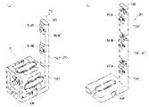
- FIG. 7 is a perspective view and an exploded view of a gantry and gas storage system according to another embodiment of the present invention.
- FIG. 7(a) shows an example of a frame 20 (gas storage system) on which the gas storage container 10 is installed.
- FIG. 7(b) shows an exploded view of the side portion 500 of the gantry 20 without the gas storage container 10 installed.
- the pedestal 20 shown in FIG. 7 is similar to the pedestal shown in FIG. 6 except that it has three power transmission units 510A to 510C and can supply power to three gas storage containers 10 stacked one above the other at the same time. It has a configuration of
- the side part 500 has three power transmission parts 510A to 510C. That is, the side portion 500 is provided with the number of power transmission units 510 corresponding to the number of loadable gas storage containers 10 .
- Each of the power transmission units 510A to 510C includes at least one power transmission member. At least one lamp is provided near each of the power transmission units 510A to 510C.
- the side part 500 is composed of three side units 500A to 500C.
- the three side units 500A-500C are separable from each other, each comprising at least one power transmission section 510A-510C.
- These side units 500A to 500C are connected to each other by being vertically stacked.
- a lid 520 is attached to the top of the side unit 510C.
- the side units 500A to 500C are at least physically connected by being vertically stacked.
- the side units 500A to 500C are typically configured to be vertically stacked and electrically connected at the same time. Adopting such a configuration eliminates the need to individually connect an external power supply to each of the side units, thereby simplifying the configuration of the gantry 20 .
- the electrical connection between the side units may be made separately using a cable or the like.
- FIG. 8 is a conceptual diagram showing an example of the configuration of the power supply section of the pedestal according to one embodiment of the present invention.
- FIG. 8A shows an example in which the side portion 500 has one power feeding portion 510 .
- FIG. 8(b) is an example in which the side part 500 has three power supply parts 510A to 510C, which are connected in series from the power supply.
- FIG. 8(c) is an example in which the side part 500 has three power supply parts 510A to 510C, which are connected in parallel from the power supply.
- the power supply unit 510 includes a power transmission member and a control unit.
- the power transmission member is supplied with current from the power supply via the control unit.
- each of the power supply units 510A to 510C includes a power transmission member and a control unit.
- the control section of power supply section 510A, the control section of power supply section 510B, and the control section of power supply section 510C are connected in series from a single power supply. That is, the control unit of the power supply unit 510A is connected to the power supply, the control unit of the power supply unit 510B is electrically connected to the control unit of the power supply unit 510A, and the control unit of the power supply unit 510C is connected to the power supply unit. It is electrically connected to the controller of 510B.
- each of the power supply units 510A to 510C includes a power transmission member and a control unit.
- the control unit of power supply unit 510A, the control unit of power supply unit 510B, and the control unit of power supply unit 510C are connected in parallel to a single power supply.
- the above configuration is merely an example, and it is also possible to perform electrical connection in other forms.
- a configuration in which a plurality of power supply units and a plurality of power supplies are individually connected may be adopted.
- the control unit may be omitted.
- the number of power supply units 510 on the side portion 500 of the gantry 20 can be adjusted according to the usage of the gas storage container 10.
- FIG. 9 is a perspective view showing an example of a gas storage system according to one embodiment of the present invention.
- FIG. 9(a) shows an example in which the side portion 500 of the gantry 20 has one power supply portion 510 (not shown) and one gas storage container 10 is installed.
- FIG. 9(b) shows an example in which the side portion 500 of the pedestal 20 has two feeders 510A and 510B (not shown) and two gas storage containers 10A and 10B are installed.
- FIG. 9(c) shows an example in which the side portion 500 of the gantry 20 has three feeders 510A to 510C (not shown) and three gas storage containers 10A to 10C are installed.
- FIG. 9(b) two gas storage containers 10A and 10B are stacked one above the other, and correspondingly two side units 500A and 500B are stacked one above the other.
- FIG. 9(c) three gas storage vessels 10A-10C are stacked one above the other, and correspondingly three side units 500A-500C are stacked one above the other.
- Those of the plurality of gas storage containers 10 that are in contact with the bottom portion 400 are further fixed by connecting the second grip portion 170B and the mounting portion 420 (not shown) with a fixing member 422 .
- a plurality of gas storage containers 10 are also connected to each other via auxiliary fixing members 424 .
- the connection by the auxiliary fixing member 424 is made between the first gripping portion 170A of the lower gas storage vessel and the second gripping portion 170B of the upper gas storage vessel.
- the auxiliary fixing member 424 may be omitted.
- FIG. 10 is a front view showing an example of a gas storage system in which pedestals according to one embodiment of the present invention are arranged in the horizontal direction.
- the gas storage system shown in FIG. 10 includes three horizontally arranged racks 20 ⁇ to 20 ⁇ and three gas storage containers 10 ⁇ to 10 ⁇ installed on each rack.
- the pedestals 20 ⁇ to 20 ⁇ are horizontally connected to each other at their bottoms 400 ⁇ to 400 ⁇ .
- This connection is typically made by a horizontal fixing member 430 via a mounting portion 420 (not shown).
- the outermost gas storage containers 10 ⁇ and 10 ⁇ are fixed by the bottoms 400 ⁇ and 400 ⁇ of the mounts 20 ⁇ and 20 ⁇ and fixing members 422, respectively.
- the gas storage containers 10 adjacent to each other are further fixed by fitting together the convex portion 150A provided on the right side portion 150 and the concave portion 160A (not shown) provided on the left side portion 160.
- the horizontal fixing member 430, the fixing member 422, the convex portion 150A and the concave portion 160A may be omitted.
- a configuration may be employed in which electrical connection is performed simultaneously with physical connection between the plurality of pedestals 20 .
- a power source is connected to at least one of the plurality of cradles 20, power can be supplied to the gas storage container 10 by other cradles 20 that are not connected to the power source.
- the configuration in which the bottom portion 400 is provided with the convex portion 410 has been described, but the configuration of the convex portion is not particularly limited.
- the bottom portion 400 is preferably provided with a corresponding concave portion.
- the convex portion 410 may be omitted.
- the fixing member 422, the auxiliary fixing member 424, and the horizontal fixing member 430 have been described in the examples shown in FIGS. Moreover, although the fixing member 422 and the auxiliary fixing member 424 are connected via the holding portion of the gas storage container 10, the fixing member 422 and the auxiliary fixing member 424 are connected via other locations. may Also, the fixing member 422 and the horizontal fixing member 430 are connected via the mounting portion 420 of the bottom portion 400, but the fixing member 422 and the horizontal fixing member 430 are connected via other locations. you can go Also, as described above, these fixing members may be omitted.
- the side part 500 is configured by a plurality of side units that can be separated from each other, but the side part 500 may be configured by a single unit.
- the side part 500 may consist of a single unit having a plurality of power transmission parts.
- FIG. 9 describes a gas storage system in which the gas storage containers 10 are stacked only vertically
- FIG. 10 describes a gas storage system in which the gas storage containers 10 are arranged only horizontally.
- each of the gas storage containers 10 can store different types of gas.
- a gas storage system capable of supplying a plurality of types of gases.
- the substantial storage capacity of the gas can be increased. In this way, by customizing the configuration of the gas storage container 10 and the frame 20, it is possible to provide a flexible gas storage system that meets the user's wishes.
- a gas storage container comprising a casing having a flat upper surface and a lower surface that can be stacked vertically, a gas container installed in the casing, and a remaining gas measuring module is used.
- the remaining gas amount measuring module equipped with such a power receiving member can be applied to any shape of gas storage container. It can also be used for general purposes. That is, such a remaining gas amount measuring module can be applied to gas storage containers of any shape that are not stackable.
Landscapes
- Engineering & Computer Science (AREA)
- Mechanical Engineering (AREA)
- General Engineering & Computer Science (AREA)
- Power Engineering (AREA)
- Physics & Mathematics (AREA)
- Fluid Mechanics (AREA)
- General Physics & Mathematics (AREA)
- Computer Networks & Wireless Communication (AREA)
- Electromagnetism (AREA)
- Thermal Sciences (AREA)
- Filling Or Discharging Of Gas Storage Vessels (AREA)
Priority Applications (4)
| Application Number | Priority Date | Filing Date | Title |
|---|---|---|---|
| US18/575,313 US20240309998A1 (en) | 2021-06-30 | 2022-06-30 | Gas storage container, pedestal, and gas storage system |
| EP22833278.9A EP4365478A4 (en) | 2021-06-30 | 2022-06-30 | GAS STORAGE TANK, FRAME AND GAS STORAGE SYSTEM |
| JP2023532052A JPWO2023277132A1 (https=) | 2021-06-30 | 2022-06-30 | |
| CN202280046885.1A CN117597537A (zh) | 2021-06-30 | 2022-06-30 | 储气容器、基座和储气系统 |
Applications Claiming Priority (2)
| Application Number | Priority Date | Filing Date | Title |
|---|---|---|---|
| JP2021-108444 | 2021-06-30 | ||
| JP2021108444 | 2021-06-30 |
Publications (1)
| Publication Number | Publication Date |
|---|---|
| WO2023277132A1 true WO2023277132A1 (ja) | 2023-01-05 |
Family
ID=84692766
Family Applications (1)
| Application Number | Title | Priority Date | Filing Date |
|---|---|---|---|
| PCT/JP2022/026224 Ceased WO2023277132A1 (ja) | 2021-06-30 | 2022-06-30 | ガス貯蔵容器、架台、及びガス貯蔵システム |
Country Status (5)
| Country | Link |
|---|---|
| US (1) | US20240309998A1 (https=) |
| EP (1) | EP4365478A4 (https=) |
| JP (1) | JPWO2023277132A1 (https=) |
| CN (1) | CN117597537A (https=) |
| WO (1) | WO2023277132A1 (https=) |
Cited By (1)
| Publication number | Priority date | Publication date | Assignee | Title |
|---|---|---|---|---|
| EP4596954A1 (de) * | 2024-02-02 | 2025-08-06 | Messer SE & Co. KGaA | Transportabler gasbehälter mit elektronischen funktionskomponenten |
Families Citing this family (1)
| Publication number | Priority date | Publication date | Assignee | Title |
|---|---|---|---|---|
| GB2643175A (en) * | 2024-08-02 | 2026-02-11 | Advanced Automation Tech Limited | A power distribution system for powering refrigerated containers |
Citations (7)
| Publication number | Priority date | Publication date | Assignee | Title |
|---|---|---|---|---|
| JPH02120331U (https=) * | 1989-03-16 | 1990-09-28 | ||
| JP2014204539A (ja) * | 2013-04-03 | 2014-10-27 | 船井電機株式会社 | 非接触給電器および非接触給電方法 |
| JP2014532011A (ja) * | 2011-09-09 | 2014-12-04 | ザ チラフィッシュ カンパニー エンフェーThe CHILLAFISH Company NV | 貯蔵容器 |
| JP2016158367A (ja) * | 2015-02-24 | 2016-09-01 | 株式会社デンソー | 非接触給電装置 |
| JP2017147849A (ja) * | 2016-02-17 | 2017-08-24 | 富士機械製造株式会社 | 非接触給電装置 |
| WO2019026872A1 (ja) | 2017-07-31 | 2019-02-07 | 株式会社Atomis | ガス貯蔵容器 |
| CN211450330U (zh) * | 2020-01-07 | 2020-09-08 | 广东环球净化科技有限公司 | 一种蒸汽压力储气罐 |
Family Cites Families (10)
| Publication number | Priority date | Publication date | Assignee | Title |
|---|---|---|---|---|
| DE20116268U1 (de) * | 2001-10-04 | 2003-02-20 | Scheuermann, Frank, 45739 Oer-Erkenschwick | Anordnung zur berührungslosen Überwachung von Druckgasbehältern |
| US6976594B1 (en) * | 2003-09-26 | 2005-12-20 | Young Richard E | Cylinder holder for impact resistant storage |
| US20070114200A1 (en) * | 2004-11-05 | 2007-05-24 | Lane Dean V | Stackable bottle system |
| US20080251074A1 (en) * | 2007-04-12 | 2008-10-16 | Sand Robert H | System and method for remote oxygen supply monitoring and calculation of replacement requirements |
| FR2918735B1 (fr) * | 2007-07-12 | 2010-09-03 | Messier Bugatti | Bouteille de gaz equipee d'un capteur radiofrequence |
| FR2985802B1 (fr) * | 2012-01-17 | 2014-03-14 | Air Liquide | Element modulaire de distribution de gaz sous pression et installation correspondante |
| GB201504453D0 (en) * | 2015-03-17 | 2015-04-29 | Linde Ag | A digital valve assembly |
| RU2702383C2 (ru) * | 2015-07-31 | 2019-10-08 | Бомбардье Рекриэйшенел Продактс Инк. | Контейнер для хранения для транспортного средства и транспортное средство (варианты) |
| US10865015B2 (en) * | 2017-05-25 | 2020-12-15 | Apex Coolers, Llc | Storage container securing system |
| LU100578B1 (en) * | 2017-12-15 | 2019-06-28 | Luxembourg Patent Co | Tap assembly with rechargeable battery |
-
2022
- 2022-06-30 JP JP2023532052A patent/JPWO2023277132A1/ja active Pending
- 2022-06-30 EP EP22833278.9A patent/EP4365478A4/en active Pending
- 2022-06-30 US US18/575,313 patent/US20240309998A1/en active Pending
- 2022-06-30 CN CN202280046885.1A patent/CN117597537A/zh active Pending
- 2022-06-30 WO PCT/JP2022/026224 patent/WO2023277132A1/ja not_active Ceased
Patent Citations (7)
| Publication number | Priority date | Publication date | Assignee | Title |
|---|---|---|---|---|
| JPH02120331U (https=) * | 1989-03-16 | 1990-09-28 | ||
| JP2014532011A (ja) * | 2011-09-09 | 2014-12-04 | ザ チラフィッシュ カンパニー エンフェーThe CHILLAFISH Company NV | 貯蔵容器 |
| JP2014204539A (ja) * | 2013-04-03 | 2014-10-27 | 船井電機株式会社 | 非接触給電器および非接触給電方法 |
| JP2016158367A (ja) * | 2015-02-24 | 2016-09-01 | 株式会社デンソー | 非接触給電装置 |
| JP2017147849A (ja) * | 2016-02-17 | 2017-08-24 | 富士機械製造株式会社 | 非接触給電装置 |
| WO2019026872A1 (ja) | 2017-07-31 | 2019-02-07 | 株式会社Atomis | ガス貯蔵容器 |
| CN211450330U (zh) * | 2020-01-07 | 2020-09-08 | 广东环球净化科技有限公司 | 一种蒸汽压力储气罐 |
Non-Patent Citations (1)
| Title |
|---|
| See also references of EP4365478A4 |
Cited By (2)
| Publication number | Priority date | Publication date | Assignee | Title |
|---|---|---|---|---|
| EP4596954A1 (de) * | 2024-02-02 | 2025-08-06 | Messer SE & Co. KGaA | Transportabler gasbehälter mit elektronischen funktionskomponenten |
| DE102024103046A1 (de) * | 2024-02-02 | 2025-08-07 | Messer Se & Co. Kgaa | Transportabler Gasbehälter mit elektronischen Funktionskomponenten |
Also Published As
| Publication number | Publication date |
|---|---|
| JPWO2023277132A1 (https=) | 2023-01-05 |
| EP4365478A4 (en) | 2025-06-18 |
| CN117597537A (zh) | 2024-02-23 |
| US20240309998A1 (en) | 2024-09-19 |
| EP4365478A1 (en) | 2024-05-08 |
Similar Documents
| Publication | Publication Date | Title |
|---|---|---|
| WO2023277132A1 (ja) | ガス貯蔵容器、架台、及びガス貯蔵システム | |
| JP5562872B2 (ja) | 誘導結合された棚及び格納コンテナ | |
| US7462951B1 (en) | Portable inductive power station | |
| US8228026B2 (en) | Inductively coupled shelving and storage containers | |
| US8164222B2 (en) | Laptop and portable electronic device wireless power supply systems | |
| EP3663631B1 (en) | Gas storage container | |
| CN105978054A (zh) | 便携式电力单元 | |
| ES3036634T3 (en) | Autonomous sensor device with expansion modules | |
| US9627912B2 (en) | Mobile cart with capacitive power supply | |
| EP4637178A1 (en) | Gas storage container management system and management method, and frame | |
| WO2023277133A1 (ja) | ガス貯蔵容器 | |
| JPWO2023277132A5 (https=) | ||
| JP2014011862A (ja) | 携帯機器充電用台及び収納棚 | |
| CN214341394U (zh) | 一种智能定位安全帽展示台 | |
| EP2856462A1 (en) | Displaying device and method for using the same | |
| CN211237596U (zh) | 一种可为数码设备充电的电子桌号牌 | |
| US20160320005A1 (en) | El spool and dolly | |
| CN208257473U (zh) | 一种不倒翁耳机充电盒 | |
| CN223950508U (zh) | 一种便携式的移动灯带卷盘 | |
| CN212901429U (zh) | 一种可拆装配件 | |
| CN222215234U (zh) | 一种电池充电装置及电池 | |
| CN223565886U (zh) | 一种地基合成孔径雷达监测系统 | |
| CN220570363U (zh) | 一种无线充电结构 | |
| CN213169071U (zh) | 一种配送设备的储物装置、配送设备及系统 | |
| CN212508923U (zh) | 分体式风扇 |
Legal Events
| Date | Code | Title | Description |
|---|---|---|---|
| 121 | Ep: the epo has been informed by wipo that ep was designated in this application |
Ref document number: 22833278 Country of ref document: EP Kind code of ref document: A1 |
|
| WWE | Wipo information: entry into national phase |
Ref document number: 2023532052 Country of ref document: JP |
|
| WWE | Wipo information: entry into national phase |
Ref document number: 2301008539 Country of ref document: TH |
|
| WWE | Wipo information: entry into national phase |
Ref document number: 202280046885.1 Country of ref document: CN |
|
| WWE | Wipo information: entry into national phase |
Ref document number: 202417003022 Country of ref document: IN |
|
| WWE | Wipo information: entry into national phase |
Ref document number: 2022833278 Country of ref document: EP |
|
| NENP | Non-entry into the national phase |
Ref country code: DE |
|
| ENP | Entry into the national phase |
Ref document number: 2022833278 Country of ref document: EP Effective date: 20240130 |