WO2023276349A1 - ホースクランプ構造及び作業機 - Google Patents
ホースクランプ構造及び作業機 Download PDFInfo
- Publication number
- WO2023276349A1 WO2023276349A1 PCT/JP2022/014354 JP2022014354W WO2023276349A1 WO 2023276349 A1 WO2023276349 A1 WO 2023276349A1 JP 2022014354 W JP2022014354 W JP 2022014354W WO 2023276349 A1 WO2023276349 A1 WO 2023276349A1
- Authority
- WO
- WIPO (PCT)
- Prior art keywords
- vertical plate
- plate
- opening
- hose
- clamp
- Prior art date
- Legal status (The legal status is an assumption and is not a legal conclusion. Google has not performed a legal analysis and makes no representation as to the accuracy of the status listed.)
- Ceased
Links
Images


Classifications
-
- E—FIXED CONSTRUCTIONS
- E02—HYDRAULIC ENGINEERING; FOUNDATIONS; SOIL SHIFTING
- E02F—DREDGING; SOIL-SHIFTING
- E02F9/00—Component parts of dredgers or soil-shifting machines, not restricted to one of the kinds covered by groups E02F3/00 - E02F7/00
- E02F9/20—Drives; Control devices
- E02F9/22—Hydraulic or pneumatic drives
- E02F9/2264—Arrangements or adaptations of elements for hydraulic drives
- E02F9/2275—Hoses and supports therefor and protection therefor
-
- B—PERFORMING OPERATIONS; TRANSPORTING
- B60—VEHICLES IN GENERAL
- B60R—VEHICLES, VEHICLE FITTINGS, OR VEHICLE PARTS, NOT OTHERWISE PROVIDED FOR
- B60R16/00—Electric or fluid circuits specially adapted for vehicles and not otherwise provided for; Arrangement of elements of electric or fluid circuits specially adapted for vehicles and not otherwise provided for
- B60R16/08—Electric or fluid circuits specially adapted for vehicles and not otherwise provided for; Arrangement of elements of electric or fluid circuits specially adapted for vehicles and not otherwise provided for fluid
-
- E—FIXED CONSTRUCTIONS
- E02—HYDRAULIC ENGINEERING; FOUNDATIONS; SOIL SHIFTING
- E02F—DREDGING; SOIL-SHIFTING
- E02F3/00—Dredgers; Soil-shifting machines
- E02F3/04—Dredgers; Soil-shifting machines mechanically-driven
- E02F3/96—Dredgers; Soil-shifting machines mechanically-driven with arrangements for alternate or simultaneous use of different digging elements
- E02F3/963—Arrangements on backhoes for alternate use of different tools
- E02F3/964—Arrangements on backhoes for alternate use of different tools of several tools mounted on one machine
-
- E—FIXED CONSTRUCTIONS
- E02—HYDRAULIC ENGINEERING; FOUNDATIONS; SOIL SHIFTING
- E02F—DREDGING; SOIL-SHIFTING
- E02F9/00—Component parts of dredgers or soil-shifting machines, not restricted to one of the kinds covered by groups E02F3/00 - E02F7/00
- E02F9/08—Superstructures; Supports for superstructures
- E02F9/0858—Arrangement of component parts installed on superstructures not otherwise provided for, e.g. electric components, fenders, air-conditioning units
- E02F9/0866—Engine compartment, e.g. heat exchangers, exhaust filters, cooling devices, silencers, mufflers, position of hydraulic pumps in the engine compartment
-
- F—MECHANICAL ENGINEERING; LIGHTING; HEATING; WEAPONS; BLASTING
- F16—ENGINEERING ELEMENTS AND UNITS; GENERAL MEASURES FOR PRODUCING AND MAINTAINING EFFECTIVE FUNCTIONING OF MACHINES OR INSTALLATIONS; THERMAL INSULATION IN GENERAL
- F16L—PIPES; JOINTS OR FITTINGS FOR PIPES; SUPPORTS FOR PIPES, CABLES OR PROTECTIVE TUBING; MEANS FOR THERMAL INSULATION IN GENERAL
- F16L5/00—Devices for use where pipes, cables or protective tubing pass through walls or partitions
-
- E—FIXED CONSTRUCTIONS
- E02—HYDRAULIC ENGINEERING; FOUNDATIONS; SOIL SHIFTING
- E02F—DREDGING; SOIL-SHIFTING
- E02F9/00—Component parts of dredgers or soil-shifting machines, not restricted to one of the kinds covered by groups E02F3/00 - E02F7/00
- E02F9/20—Drives; Control devices
- E02F9/22—Hydraulic or pneumatic drives
- E02F9/2278—Hydraulic circuits
- E02F9/2285—Pilot-operated systems
-
- F—MECHANICAL ENGINEERING; LIGHTING; HEATING; WEAPONS; BLASTING
- F16—ENGINEERING ELEMENTS AND UNITS; GENERAL MEASURES FOR PRODUCING AND MAINTAINING EFFECTIVE FUNCTIONING OF MACHINES OR INSTALLATIONS; THERMAL INSULATION IN GENERAL
- F16L—PIPES; JOINTS OR FITTINGS FOR PIPES; SUPPORTS FOR PIPES, CABLES OR PROTECTIVE TUBING; MEANS FOR THERMAL INSULATION IN GENERAL
- F16L5/00—Devices for use where pipes, cables or protective tubing pass through walls or partitions
- F16L5/02—Sealing
- F16L5/14—Sealing for double-walled or multi-channel pipes
Definitions
- the present invention relates to a hose clamp structure and a working machine.
- a hose clamp structure disclosed in Patent Document 1 is known.
- a notch recess is formed in the upper part of a partition plate that partitions the lower front part of a motor chamber that houses a motor, and is recessed downward from the upper end of the partition plate.
- a grommet that sandwiches the hose in the vertical direction is inserted into the notch recess, and a retaining plate that prevents the grommet from coming off from the notch recess is attached to the partition plate.
- the grommet and the retainer plate are pressed from above by a sealing body provided in the .
- Patent Literature 1 has a problem of poor maintainability because it is necessary to remove the partition when removing the hose.
- SUMMARY OF THE INVENTION It is an object of the present invention to provide a hose clamp structure and a working machine that can easily remove a hose.
- a hose clamp structure includes a vertical plate having an opening, and provided adjacent to the opening on the back side of one side of the vertical plate in the direction parallel to the plate surface with respect to the opening. a groove that is open to the opening side in the direction parallel to the plate surface; a receiving portion that is provided on the back side of the vertical plate on the other side of the opening in the direction parallel to the plate surface; a first clamping member to be inserted; and a first clamping member that is inserted into the groove and is arranged to contact the receiving portion from the front side of the vertical plate through the opening.
- a second clamping member formed of an elastic member that sandwiches the hose inserted through the first clamping member with the first clamping member, and the second clamping member that is elastically deformed by pressing the second clamping member from the front side of the vertical plate a pressing member attached to the vertical plate to press the first clamping member by a pressing member.
- the first clamp member is formed to have a thickness substantially equal to the groove width of the groove portion, and the second clamp member is in contact with the receiving portion and is positioned at the opening portion in a state before being pressed by the pressing member. and the holding member is fixed to the main plate inserted into the opening to hold down the second clamp member, and and a mounting plate attached to the vertical plate in contact with the front surface of the vertical plate.
- the vertical plate has an insertion groove formed from an outer edge of the vertical plate toward the opening so as to communicate with the opening, and through which the hose can pass in a direction perpendicular to the longitudinal direction of the hose.
- the groove portion has a first portion that is a portion of the vertical plate that forms an edge portion on one side of the opening in the direction parallel to the plate surface, and the groove portion is opposed to the first portion on the back side of the vertical plate. and a third portion extending from the end of the second portion on one side in the direction parallel to the plate surface toward the back surface of the vertical plate and fixed to the vertical plate. ing.
- the receiving portion includes a first wall facing the opening on the back side of the vertical plate, and the other side end of the first wall in the direction parallel to the plate surface toward the back of the vertical plate. and a second wall portion fixed to the vertical plate, wherein the second clamp member extends from the front side of the vertical plate to the first wall portion and the second wall portion through the opening. It is arranged so as to abut against the wall.
- a work machine includes a machine body, a prime mover mounted on the machine body, a partition wall separating a prime mover chamber containing the prime mover from the outside of the prime mover room, the hose clamp structure,
- the vertical plate constitutes a part of the partition wall, and the hose is routed from the engine room to the outside of the partition wall.
- the hose can be easily removed simply by removing the pressing member from the vertical plate.
- FIG. 3 is a front perspective view showing where hose clamps are provided; Fig. 3 is an exploded perspective view of where the hose clamp is provided; 3 is an exploded perspective view of a cover member and the like; FIG. It is an exploded perspective view of a hose clamp. It is a front view which shows a hose clamp structure. It is a front view which shows a hose clamp structure. It is a front view which shows a hose clamp structure. It is a rear view which shows a hose clamp structure. It is a plane sectional view which shows a hose clamp structure. It is a side sectional view showing a hose clamp structure. It is a plane sectional view showing an example of a method of assembling a hose.
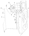
- FIG. 1 is a schematic side view showing the overall configuration of a working machine 1 according to this embodiment.
- a backhoe which is a turning work machine
- the working machine 1 includes a machine body (swivel base) 2 , a traveling device 3 , and a working device 4 .
- the aircraft 2 is equipped with a driver's seat 6 on which an operator (driver) sits.
- the direction toward the front of the operator seated on the driver's seat 6 of the work machine 1 is forward (the front of the machine body), and the direction toward the rear of the operator (direction of arrow A2 in FIG. 1) 1 is defined as the rearward direction (backward direction of the fuselage), and the direction of the arrow K1 in FIG.
- the direction toward the left side of the operator front side in FIG. 1 will be described as the left side
- the direction toward the right side of the operator back side in FIG. 1 will be described as the right side.
- the horizontal direction which is the direction orthogonal to the longitudinal direction K1
- the body width direction The direction from the central portion in the width direction of the body 2 to the right or left portion will be described as the outer side in the width direction of the body. That is, the outer side in the body width direction is the direction away from the center of the body 2 in the width direction in the body width direction.
- the direction opposite to the outer side in the width direction of the machine body will be described as the inner side in the width direction of the machine body. That is, the inner side in the width direction of the body is the direction toward the center of the width direction of the body 2 in the width direction of the body.
- the traveling device 3 is a crawler-type traveling device that supports the body 2 so as to be able to travel, and includes a traveling frame 3A, a first traveling device 3L provided on the left side of the traveling frame 3A, and a second traveling device 3R provided on the right side of the traveling frame 3A.
- the first travel device 3L and the second travel device 3R are driven by a travel motor M1 configured by a hydraulic motor (hydraulic actuator).
- a dozer device 7 is attached to the front portion of the traveling device 3 .
- the dozer device 7 can be driven by a dozer cylinder configured by a hydraulic cylinder (hydraulic actuator).
- the fuselage 2 is supported on the travel device 3 via a swivel bearing 8 so as to be able to swivel about a swivel axis X1 extending vertically.
- the machine body 2 has a support bracket 9 and a swing bracket 10 for supporting the working device 4 at the front.
- the support bracket 9 is provided so as to protrude forward from the body 2 .
- the swing bracket 10 is attached to the front portion of the support bracket 9 so as to be able to swing about a vertical axis (an axis extending in the vertical direction).
- the working device 4 has a boom 11, an arm 12 and a bucket 13.
- the base of the boom 11 is pivotally attached to an upper portion of the swing bracket 10 so as to be rotatable about a horizontal axis (an axis extending in the width direction of the machine body).
- the arm 12 is pivotally attached to the tip side of the boom 11 so as to be rotatable about the horizontal axis.
- the bucket 13 is provided on the tip side of the arm 12 so as to be able to scoop and dump.
- the squeezing operation is an operation for swinging the bucket 13 in a direction to bring it closer to the boom 11, and is an operation for scooping up earth and sand, for example.
- a dumping operation is an operation for swinging the bucket 13 in a direction away from the boom 11, and is an operation for dropping (discharging) scooped earth and sand, for example.
- the work machine 1 can be equipped with other work implements (hydraulic attachments) that can be driven by hydraulic actuators.
- Other working tools include hydraulic breakers, hydraulic crushers, angle blooms, earth augers, pallet forks, sweepers, mowers, snow blowers, and the like.
- the swing bracket 10 is swingable by extension and contraction of a swing cylinder (not shown).
- the boom 11 is swingable by extension and contraction of the boom cylinder C2.
- the arm 12 is swingable by extension and contraction of the arm cylinder C3.
- the bucket 13 is capable of squeezing and dumping by extension and contraction of the bucket cylinder C4.
- the swing cylinder, boom cylinder C2, arm cylinder C3, and bucket cylinder C4 are configured by hydraulic cylinders (hydraulic actuators).
- a motor E1 is mounted at the rear of the airframe 2.
- Prime mover E1 is a diesel engine.
- the prime mover E1 may be a gasoline engine, an electric motor, or a hybrid type having an engine and an electric motor.
- a driver's seat 6, a travel lever 16 arranged in front of the driver's seat 6, a control device 17L arranged on the left side of the driver's seat 6, a control device 17R arranged on the right side, etc. is mounted.
- the travel lever 16 is an operating member that operates the travel device 3 .
- the control devices 17L and 17R are devices that perform, for example, a swinging operation of the boom 11, a swinging operation of the arm 12, a scooping operation and a dumping operation of the bucket 13, a turning operation of the machine body 2, and the like.
- a step 21 constituting a floor surface is provided on the upper surface side of the body 2 and on the front side of the driver's seat 6 .
- the airframe 2 has a revolving frame 30 that serves as a skeleton.
- the revolving frame 30 has a revolving base (substrate) 31 forming the bottom of the machine body 2, reinforcing ribs 32 reinforcing the revolving base 31, support brackets 9 and weights 33 (see FIG. 1).
- the swing frame 30 also has brackets, stays, and the like for attaching devices, tanks, and other parts to be mounted on the body 2 .
- the swivel base plate 31 is formed of a thick steel plate or the like. Brackets, stays, and the like mounted on the revolving frame 30 are fixed on the revolving base plate 31 by welding or the like.
- the swivel base plate 31 is rotatably supported on the travel device 3 via the swivel bearing 8 around the swivel axis X1.
- the reinforcing rib 32 is formed of a plate material, and is provided on the swivel base plate 31 from the front portion toward the rear portion.
- the reinforcing ribs 32 are composed of a first longitudinal rib 32R extending rearward from the left rear portion of the support bracket 9 provided on the front portion of the turning base plate 31, and a first vertical rib 32R extending rearward from the right rear portion of the support bracket 9. 2 longitudinal ribs 32L.
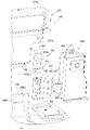
- a control valve V1 As shown in FIG. 2, a control valve V1, a hydraulic oil tank 28, a swing motor 20, and the like are mounted on the swing base plate 31. As shown in FIG. The control valve V ⁇ b>1 is arranged on the front part of the left part of the swivel base plate 31 .
- the control valve V1 controls the flow rate of hydraulic fluid supplied to a hydraulic actuator mounted on the work machine 1 and driven by hydraulic fluid.
- the control valve V ⁇ b>1 is a valve unit that integrates control valves that control the flow rate of hydraulic oil supplied to the hydraulic actuators of the work machine 1 .
- the hydraulic oil tank 28 is arranged behind the control valve V1.
- the hydraulic oil tank 28 is a tank that stores hydraulic oil.
- the prime mover E1 is mounted on the rear part of the turning board 31.
- a hydraulic pump 25 is attached to one side portion (left portion) of the prime mover E1 in the body width direction.
- the hydraulic pump 25 is driven by the power of the prime mover E1.
- the hydraulic pump 25 sucks the hydraulic oil in the hydraulic oil tank 28 and discharges hydraulic oil (pressure oil) for driving hydraulic actuators such as hydraulic motors and hydraulic cylinders installed in the working machine 1 .
- the hydraulic pump 25 discharges pilot pressure for operating hydraulic valves and hydraulic pressure for signals.
- a cooling fan 14 is provided to the right of the prime mover E1, and a radiator, an oil cooler, a fuel cooler, and the like are arranged to the right of the cooling fan 14.
- a partition wall 36 is provided in front of the prime mover E1 to define the front side of the prime mover chamber E2 that houses the prime mover E1.
- the partition wall 36 is a member that separates the motor room E2 and the front side of the motor room E2 (outside the motor room E2).
- the hydraulic oil tank 28 is arranged on the left side of the partition wall 36 .
- the hydraulic oil tank 28 is installed on the turning base plate 31 .
- the partition 36 has a partition main body 37 and a partition plate 38 .
- the partition main body 37 is a member that separates the motor chamber E2 from the upper front portion of the motor chamber E2, and has an upper wall 37a and a front wall 37b that extends downward from the front portion of the upper wall 37a.
- the partition plate 38 is arranged below the partition main body 37 .
- the partition plate 38 is arranged below the step 21 .
- the partition plate 38 is a member that partitions the lower front part of the engine room E2.
- the partition plate 38 has a first partition plate 38A and a second partition plate 38B.
- the first partition plate 38A is erected on the swivel base plate 31 so that the plate surface faces the front-rear direction K1. Also, the first partition plate 38A is arranged on the turning base plate 31 so as to extend in the machine body width direction and is fixed to the turning base plate 31 by welding or the like.
- the second partition plate 38B has a lower portion fixed to the rear surface of the first partition plate 38A by welding or the like, and a left portion fixed to the turning base plate 31 by welding or the like.
- a lower portion of the partition main body 37 (a lower portion of the front wall 37b) is attached to the second partition plate 38B. As shown in FIG. 6, the second partition plate 38B protrudes leftward from the first partition plate 38A.
- a cover member 39 and a hose clamp 43 are provided between the partition wall 36 and the hydraulic oil tank 28.
- a hose clamp 43 is arranged below the cover member 39 .
- the cover member 39 and the hose clamp 43 block the gap between the partition wall 36 and the hydraulic oil tank 28 .
- the cover member 39 and the hose clamp 43 form part of the partition wall 36 .
- the cover member 39 has a first cover 40, a second cover 41 and a third cover .
- the first cover 40 is formed in a rectangular shape having a U-shaped notch groove 40a opening leftward.
- the cutout groove 40a is for passing a routing member such as a harness in which wires are bundled, and the gap between the cutout groove 40a and the harness is sealed by a grommet.
- the second cover 41 has a first portion 41a, a second portion 41b, and a third portion (extending portion) 41c.
- the first portion 41a is fixed to the lower end portion and the front side of the first cover 40 by welding or the like.
- the second portion 41b is fixed to the front side of the left end portion of the first cover 40 by welding or the like below the cutout groove 40a.
- the third portion 41c extends downward from the left portion of the first portion 41a.
- the third cover 42 is formed in a horizontally long rectangular shape having a U-shaped notch 42a opening downward.
- the notch groove 42a is formed to the right of the center portion of the third cover 42 in the machine body width direction.
- the upper portion of the third cover 42 is fixed to the front surface of the second portion 41b of the second cover 41 by welding or the like.
- the cutout groove 42a is shifted to the right with respect to the third portion 41c of the second cover 41 .
- the notch groove 42a is a groove for avoiding interference between the third cover member 42 and an upper mounting plate 57A of a pressing member 48, which will be described later.
- the first cover 40 is bolted to the front wall 37b of the bulkhead body 37, and the second cover 41 is a flange plate fixed to the hydraulic oil tank 28 by welding or the like so as to protrude outward from the hydraulic oil tank 28. 44 is bolted. A notch portion 44a is formed in the lower portion of the flange plate 44 for avoiding interference with a groove portion 50, which will be described later (see FIG. 11).
- the third cover 42 is bolted to the second partition plate 38B and the flange plate 44 together with a vertical plate 49 to be described later.
- the hose clamp 43 is a member that holds a hose such as the hydraulic hose 45 routed from the engine E1 to the front side of the partition wall 36 (outside the engine E1).
- a hose clamp 43 is provided between the partition plate 38 and the hydraulic oil tank 28 . Therefore, the hose clamp 43 is arranged below the step 21 (inside the body 2) together with the control valve V1.
- a plurality of hydraulic hoses 45 are held by the hose clamps 43 . Most of the plurality of hydraulic hoses 45 are hoses that connect the hydraulic pump 25 and the control valve V1. As shown in FIG. 4, in this embodiment, the number of hydraulic hoses 45 is seven.
- the seven hydraulic hoses 45 are arranged side by side in the vertical direction, and two hydraulic hoses 45a at the top and three hydraulic hoses 45a at the bottom are hydraulic hoses with smaller hose diameters than the two hydraulic hoses 45b at the middle. be.
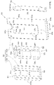
- the hose clamp 43 includes a holder 46 attached to the machine body 2, a clamp 47 held by the holder 46 and clamping the hydraulic hose 45, and a holding member 48 holding the clamp 47. have.
- the holder 46 has a vertical plate 49 , a groove portion 50 , a receiving portion 51 and a connecting plate 52 .
- the vertical plate 49 is arranged so that the plate surface faces the front-rear direction K1. That is, the vertical plate 49 is arranged such that the plate width direction (direction parallel to the plate surface) W1 perpendicular to the vertical direction is aligned with the machine body width direction, and the plate thickness direction is aligned with the longitudinal direction K1.
- the vertical plate 49 has an opening 53 and an insertion groove 54 .
- the vertical plate 49 includes a first vertical wall portion 49a which is a portion (left portion) on one side (the left side in the width direction of the machine body; the right side in FIG. 8) in the width direction W1, and the other portion in the width direction W1.
- a second vertical wall portion 49b that is a portion (right portion) on the side (right side in the width direction of the machine body; left side in FIG. 8) and is spaced apart from the first vertical wall portion 49a in the plate width direction W1;
- An extension wall 49c extending from the upper portion of the second vertical wall portion 49b toward the upper side of the first vertical wall portion 49a, and a lower wall 49d connecting the lower portions of the first vertical wall portion 49a and the second vertical wall portion 49b. and A space is provided between the extension wall 49c and the upper portion of the first vertical wall portion 49a.
- the opening 53 is formed by a first vertical wall portion 49a, a second vertical wall portion 49b, an extension wall 49c, and a lower wall 49d.
- the opening 53 includes one side edge (left edge) 53a that is the edge on one side in the sheet width direction W1 and the other side edge that is the edge on the other side in the sheet width direction W1. It has a (right edge) 53b, an upper edge 53c, and a lower edge 53d.
- the insertion groove 54 is formed between the extension wall 49c and the upper portion of the first vertical wall portion 49a. That is, the insertion groove 54 is formed from the upper end of the vertical plate 49 toward the opening 53 so as to communicate with the opening 53 .
- the insertion groove 54 is formed with a groove width W2 through which the hydraulic hose 45 held by the hose clamp 43 can pass in the direction orthogonal to the longitudinal direction of the hydraulic hose 45 .
- the vertical plate 49 has the third cover 42 superimposed on the front side (front side) of the vertical plate 49, and the second partition plate 38B and the flange plate 44 are attached together with the third cover 42. It is bolted on by tightening.
- the notch groove 42a of the third cover 42 is located at a position corresponding to the extending wall 49c of the vertical plate 49.
- the third portion 41 c of the second cover 41 is inserted into the insertion groove 54 . Further, the third portion 41 c protrudes slightly from the insertion groove 54 into the opening 53 .
- the vertical plate 49 is formed with a fixed wall 49e extending forward from the lower end of the lower wall 49d.
- the fixed wall 49e is bolted onto the swivel base plate 31, as shown in FIG.
- the cover member 39 is attached to the front surface of the upper portion of the vertical plate 49 so that the third cover 42 is mounted. Place it in position.
- first cover 40 is bolted to the front wall 37b
- second cover 41 is bolted to the flange plate 44
- third cover 42 and the vertical plate 49 are connected to the second partition plate 38B and the flange plate 44 by bolts. Tighten together with bolts.
- Any of the first cover 40, the second cover 41, and the third cover 42 may be fixed first.
- the fixed wall 49e of the vertical plate 49 can be bolted to the swivel base plate 31.
- the vertical plate 49 is not limited to the configuration described above, and for example, the extension wall 49c may be connected to the upper portion of the first vertical wall portion 49a. That is, the insertion groove 54 does not necessarily need to be provided. Further, the first vertical wall portion 49a and the second vertical wall portion 49b are not limited to be arranged so as to extend in the vertical direction, but may be arranged so as to extend in the horizontal direction or diagonal direction. In other words, the vertical plate 49 may be arranged such that the plate width direction W1 coincides with the vertical direction or an oblique direction that is slanted with respect to the vertical direction.
- the groove portion 50 is provided adjacent to the opening portion 53 on one side of the vertical plate 49 in the plate width direction W1 on the rear surface 49f side.
- the groove portion 50 is formed by a first portion 50a, a second portion 50b, and a third portion 50c.
- the first portion 50 a is formed by the right portion of the first vertical wall portion 49 a of the vertical plate 49 .
- the first portion 50 a is a portion of the vertical plate 49 and is configured by the portion of the vertical plate 49 forming one side edge 53 a of the opening 53 .
- the second portion 50b faces the first portion 50a with a gap therebetween on the rear surface 49f of the first portion 50a (vertical plate 49).
- the third portion 50c extends from the end (left end) of the second portion 50b on one side in the plate width direction W1 toward the rear surface 49f of the (vertical plate 49) of the first portion 50a. It is fixed to the portion 50a (vertical plate 49) by welding or the like. Therefore, the groove portion 50 is opened (opened) to the opening portion 53 side (right side) in the plate width direction W1. Moreover, the groove part 50 is formed so as to extend in the vertical direction. A first extending wall 50d extending rightward from the upper end of the third portion 50c is formed at the upper end of the third portion 50c.
- the receiving portion 51 is provided on the rear surface 49f side of the vertical plate 49 (opening portion 53) on the other side in the plate width direction W1.
- the receiving portion 51 has a first wall portion 51a and a second wall portion 51b.
- the first wall portion 51a is arranged facing the opening portion 53 on the back surface 49f side of the vertical plate 49 .
- the second wall portion 51b extends from the end (right end) of the first wall portion 51a on the other side in the plate width direction W1 toward the rear surface 49f of the vertical plate 49 and is welded to the vertical plate 49 or the like. Fixed.
- the left surface of the second wall portion 51 b is substantially flush with the other side edge portion 53 b of the opening 53 .
- the receiving portion 51 is formed so as to extend in the vertical direction.
- a second extending wall 51c extending leftward (first extending wall 50d) from the upper end is formed at the upper end of the second wall 51b.
- the first extending wall 50d and the second extending wall 51c are space
- the connecting plate 52 is formed in a strip shape whose plate surface faces the vertical direction and is elongated in the plate width direction W1, and connects the lower end of the third portion 50c and the lower end of the second wall portion 51b.
- the pressing member 48 has a main plate 56 and a mounting plate 57 .
- the main plate 56 is formed of a vertically elongated strip material whose plate surface faces the front-rear direction K1.
- the main plate 56 is inserted into the opening 53 to hold down a second clamp member 59, which will be described later.
- the mounting plate 57 is fixed to the main plate 56 by welding or the like, contacts the front surface of the vertical plate 49 , and is attached to the vertical plate 49 with bolts 61 . As shown in FIG.
- the length of the main plate 56 in the vertical direction is a length that allows the main plate 56 to be inserted into the opening 53, and is formed to have substantially the same length as the vertical dimension of the opening 53.
- the mounting plate 57 is provided on the top and bottom of the main plate 56 . That is, a pair of mounting plates 57 are provided.
- the upper mounting plate 57A has a lower portion fixed to the front surface of the main plate 56 by welding or the like, and an upper portion protruding upward from the main plate 56 .
- the lower mounting plate 57B has an upper portion fixed to the front surface of the main plate 56 by welding or the like, and a lower portion protruding downward from the main plate 56 . Therefore, when the mounting plates 57A and 57B are brought into contact with the front surface of the vertical plate 49 and attached to the vertical plate 49, the main plate 56 is inserted into the opening 53. As shown in FIG.
- the clamp tool 47 includes a first clamp member 58 and a second clamp member 59.
- the first clamp member 58 and the second clamp member 59 are made of an elastic member such as rubber.
- the clamp member 47 is formed with seven insertion holes 60 aligned in the vertical direction, through which the seven hydraulic hoses 45 are inserted in the front-rear direction K1.
- the clamp tool 47 is divided into a left first clamp member 58 and a right second clamp member 59 by dividing each insertion hole 60 into left and right. Therefore, the hydraulic hoses 45 can be held by sandwiching the hydraulic hoses 45 between the first clamp member 58 and the second clamp member 59 so that the hydraulic hoses 45 are inserted through the insertion holes 60 .
- a width W3 of the first clamp member 58 in the plate width direction W1 is formed narrower than a width W4 of the second clamp member 59 in the plate width direction W1. Also, the thickness 59a of the second clamp member 59 (the dimension in the direction orthogonal to the plate width direction W1 and the vertical direction) is thicker than the thickness 58a of the first clamp member 58 .
- the first clamp member 58 is a member that is inserted into the groove portion 50. As shown in FIG. The vertical length of the first clamp member 58 is formed to extend from the first extension wall 50 d to the connecting plate 52 . As shown in FIG. 12, the thickness 58a of the first clamping member 58 is a thickness that allows the first clamping member 58 to be inserted into the groove portion 50, and is formed to have substantially the same thickness as the groove width 50e of the groove portion 50. .
- the first clamp member 58 has a left portion inserted into the groove 50 and a right portion protruding from the groove 50 .
- Half of the insertion hole 60 is formed in the portion of the first clamp member 58 protruding from the groove portion 50 .
- the second clamp member 59 clamps the front surface of the first wall portion 51 a of the receiving portion 51 through the opening 53 from the front side (front side) of the vertical plate 49 while the first clamp member 58 is inserted into the groove portion 50 . and the left surface of the second wall portion 51b (contacts the receiving portion 51).
- FIG. 10 the first clamp member 58 has a left portion inserted into the groove 50 and a right portion protruding from the groove 50 .
- Half of the insertion hole 60 is formed in the portion of the first clamp member 58 protruding from the groove portion 50 .
- the second clamp member 59 clamps the front surface of the first wall portion 51 a of the receiving portion 51 through the opening 53 from the front side (front side) of the vertical plate
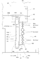
- the thickness 59a of the second clamp member 59 is formed to be larger than the distance H1 from the front surface of the first wall portion 51a to the rear surface 49f of the vertical plate 49. As shown in FIG. That is, the second clamp member 59 is formed to have a thickness that protrudes forward from the rear surface 49 f of the vertical plate 49 through the opening 53 before being pressed by the pressing member 48 . A half of the insertion hole 60 is formed in the left portion of the first clamp member 58 . The right portion of the first clamp member 58 is the portion with which the main plate 56 of the pressing member 48 abuts.
- the second clamp member 59 is vertically divided into three parts.
- the upper portion 59b corresponds to the upper two through-holes 60 of the seven through-holes 60
- the intermediate portion 59c corresponds to the two intermediate through-holes 60 of the seven through-holes 60.
- the lower portion 59 d is a portion corresponding to the three through-holes 60 on the lower side of the seven through-holes 60 .
- the hydraulic hose 45 can be held by assembling the clamp 47 and the pressing member 48 to the holder 46 .
- the first clamp member 58 is inserted into the groove portion 50 as shown in the left drawing of FIG.
- the hydraulic hose 45 passed through the opening 53 is fitted to the portion of the first clamp member 58 where the insertion hole 60 is formed (the portion where the insertion hole 60 is divided in half).
- the second clamping member 59 is applied from the front side of the vertical plate 49 to the receiving portion 51 (the first wall portion 51a and the second wall portion 51b) through the opening 53.
- the hydraulic hose 45 is sandwiched between the first clamp member 58 and the second clamp member 59 so as to be in contact with each other.
- the second clamp member 59 protrudes through the opening 53 from the rear surface 49 f of the vertical plate 49 toward the front side.
- the pressing member 48 is bolted to the vertical plate 49 . At this time, as shown in FIG.
- the main plate 56 of the pressing member 48 is inserted into the opening 53, pressing the second clamp member 59 from the front side (opposite side of the receiving portion 51) and elastically deforming it.
- the second clamp member 59 elastically deforms, the second clamp member 59 presses the hydraulic hose 45 and the first clamp member 58 , and the hose clamp 43 firmly holds the hydraulic hose 45 .
- the hydraulic hose 45 is clamped and fixed by the first clamp member 58 and the second clamp member 59 by elastically deforming the second clamp member 59, so that the pulsation of the hydraulic hose 45 can be suppressed. Damping can be improved.
- the second clamp member 59 is elastically deformed, sealing performance can be ensured, and hot air can be prevented from entering the fuselage 2 from the motor chamber E2.
- the first clamp member 58 and the second clamp member 59 can be easily removed only by removing the pressing member 48, the hydraulic hose 45 can be easily removed.
- the hose clamp 43 is attached to the body 2 after the prime mover E1 is assembled to the body 2. Specifically, first, before assembling the prime mover E1 to the machine body 2, the hydraulic hose 45 is inserted through the opening 53, and the hydraulic hose 45 is clamped between the first clamp member 58 and the second clamp member 59. and hold the hydraulic hose 45 with the hose clamp 43 . Then, while the hose clamp 43 holding the hydraulic hose 45 is placed on the motor E1, the motor E1 is lowered onto the turning base plate 31 and installed on the turning base plate 31. - ⁇ After that, for example, the hose clamp 43 is arranged forward of the installation position, and the partition main body 37 and the hydraulic oil tank 28 are assembled.
- the fixed wall 49 e of the hose clamp 43 to which the hydraulic hose 45 is attached is bolted to the swivel base plate 31 .
- the cover member 39 is arranged so that the third cover 42 is positioned in front of the top of the vertical plate 49, the first cover 40 is bolted to the front wall 37b, and the second cover 41 is bolted to the flange plate 44. do.
- the third cover 42 and the vertical plate 49 are bolted together to the second partition plate 38B and the flange plate 44 .
- the third cover 42 and the vertical plate 49 may be fastened together first, and then the first cover 40 and the second cover 41 may be fixed.
- the fixed wall 49e of the vertical plate 49 may be bolted to the turning base plate 31 after the third cover 42 and the vertical plate 49 are fastened together.
- the hydraulic hose 45 can be held by the hose clamp 43 in a wide space, and workability is good. Further, the hydraulic hose 45 can be inserted through the opening 53 via the insertion groove 54, so that the hydraulic hose 45 can be easily inserted. As a method of assembling the hydraulic hose 45 to the hose clamp 43, it is conceivable to hold the hydraulic hose 45 to the hose clamp 43 without the cover member 39 attached.
- the hydraulic hose 45 is inserted through the opening 53 through the insertion groove 54, and the first clamp member 58 and the second clamp member 59 are inserted.
- the hydraulic hose 45 is sandwiched between the two, and then the pressing member 48 is attached.
- the cover member 39 is assembled and the upper portion of the holder 46 is fixed.
- the fixed wall 49c can also be fixed to the swivel base plate 31 after the hydraulic hose 45 is attached to the holder 46 .
- the third cover 42 and the vertical plate 49 are bolted together to the second partition plate 38B and the flange plate 44, and then the fixed wall 49c is attached to the turning base plate. 31 can also be fixed. Even in this assembly method, the hydraulic hose 45 can be inserted through the opening 53 via the insertion groove 54, and the hydraulic hose 45 can be easily inserted.
- the above-described hose clamp structure includes a vertical plate 49 having an opening 53, and a back surface 49f on one side of the vertical plate 49 in a direction parallel to the plate surface (plate width direction W1) with respect to the opening 53.
- a vertical plate 49 having an opening 53, and a back surface 49f on one side of the vertical plate 49 in a direction parallel to the plate surface (plate width direction W1) with respect to the opening 53.
- a receiving portion 51 provided on the rear surface 49f of the side, a first clamp member 58 inserted into the groove portion 50, and an opening from the front side of the vertical plate 49 with the first clamp member 58 inserted into the groove portion 50.
- a second clamping member 59 formed of an elastic member that sandwiches the hose (hydraulic hose 45) inserted through the opening 53 with the first clamping member 58 so as to be in contact with the receiving portion 51 via the portion 53; a pressing member 48 attached to the vertical plate 49 so as to press the first clamp member 58 by the second clamp member 59 by pressing the second clamp member 59 from the front side of the vertical plate 49 and elastically deforming it.
- the hose (hydraulic hose 45) can be easily removed simply by removing the pressing member 48 from the vertical plate 49. Further, by elastically deforming the second clamping member 59, the hydraulic hose 45 is clamped and fixed between the first clamping member 58 and the second clamping member 59, so that the pulsation of the hose 45 composed of the hydraulic hose can be suppressed. It is possible to improve the damping property.
- the first clamp member 58 is formed to have substantially the same thickness as the groove width 50 e of the groove portion 50 , and the second clamp member 59 is in contact with the receiving portion 51 and before being pressed by the pressing member 48 , the opening portion of the opening portion.
- the holding member 48 is inserted into the opening 53 to hold down the second clamp member 59, and the main plate 56 and the main plate 56 and a mounting plate 57 that is fixed and attached to the vertical plate 49 in contact with the front surface of the vertical plate 49 .
- the vertical plate 49 is formed from the outer edge of the vertical plate 49 toward the opening 53 so as to communicate with the opening 53, and the hose 45 can pass in a direction orthogonal to the longitudinal direction of the hose 45. It has grooves 54 . With this configuration, the hose 45 can be easily passed through the opening 53 through the insertion groove 54 .
- the groove portion 50 includes a first portion 50a that is a portion of the vertical plate 49 that forms an edge portion (one side edge portion 53a) on one side of the opening portion 53 in the direction parallel to the plate surface (plate width direction W1), A second portion 50b facing the first portion 50a on the side of the rear surface 49f of the vertical plate 49, and the rear surface 49f of the vertical plate 49 from the end of the second portion 50b on one side in the direction parallel to the plate surface (plate width direction W1). and a third portion 50 c fixed to the vertical plate 49 extending toward the vertical plate 49 .
- the receiving portion 51 extends from a first wall portion 51a facing the opening portion 53 on the back surface 49f side of the vertical plate 49 and the other side end portion of the first wall portion 51a in the direction parallel to the plate surface (plate width direction W1). and a second wall portion 51b that extends toward the rear surface 49f of the vertical plate 49 and is fixed to the vertical plate 49.
- the second clamp member 59 extends from the front side of the vertical plate 49 through the opening 53. are arranged so as to abut against the first wall portion 51a and the second wall portion 51b.
- the second clamp member 59 can be elastically deformed satisfactorily by sandwiching it between the pressing member 48 and the first wall portion 51a.
- the work machine 1 includes a machine body 2, a motor E1 mounted on the machine body 2, a partition wall 36 separating a motor room E2 housing the motor E1 from the outside of the motor room E2, and any one of the hose clamp structures described above.
- the vertical plate 49 constitutes a part of the partition wall 36, and the hose 45 is routed outside the partition wall 36 from the motor chamber E2.
Landscapes
- Engineering & Computer Science (AREA)
- General Engineering & Computer Science (AREA)
- Mining & Mineral Resources (AREA)
- Civil Engineering (AREA)
- Structural Engineering (AREA)
- Mechanical Engineering (AREA)
- Component Parts Of Construction Machinery (AREA)
- Supports For Pipes And Cables (AREA)
Priority Applications (4)
| Application Number | Priority Date | Filing Date | Title |
|---|---|---|---|
| JP2023531438A JP7543565B2 (ja) | 2021-06-29 | 2022-03-25 | ホースクランプ構造及び作業機 |
| EP22832510.6A EP4365370A4 (en) | 2021-06-29 | 2022-03-25 | Hose clamp structure and work machine |
| CN202280029261.9A CN117178096B (zh) | 2021-06-29 | 2022-03-25 | 软管夹紧结构及作业机 |
| US18/536,807 US20240125095A1 (en) | 2021-06-29 | 2023-12-12 | Hose clamp structure and working machine |
Applications Claiming Priority (2)
| Application Number | Priority Date | Filing Date | Title |
|---|---|---|---|
| JP2021107840 | 2021-06-29 | ||
| JP2021-107840 | 2021-06-29 |
Related Child Applications (1)
| Application Number | Title | Priority Date | Filing Date |
|---|---|---|---|
| US18/536,807 Continuation US20240125095A1 (en) | 2021-06-29 | 2023-12-12 | Hose clamp structure and working machine |
Publications (1)
| Publication Number | Publication Date |
|---|---|
| WO2023276349A1 true WO2023276349A1 (ja) | 2023-01-05 |
Family
ID=84692637
Family Applications (1)
| Application Number | Title | Priority Date | Filing Date |
|---|---|---|---|
| PCT/JP2022/014354 Ceased WO2023276349A1 (ja) | 2021-06-29 | 2022-03-25 | ホースクランプ構造及び作業機 |
Country Status (5)
| Country | Link |
|---|---|
| US (1) | US20240125095A1 (https=) |
| EP (1) | EP4365370A4 (https=) |
| JP (1) | JP7543565B2 (https=) |
| CN (1) | CN117178096B (https=) |
| WO (1) | WO2023276349A1 (https=) |
Citations (7)
| Publication number | Priority date | Publication date | Assignee | Title |
|---|---|---|---|---|
| JPS6151298U (https=) * | 1984-09-10 | 1986-04-07 | ||
| JPS61179784U (https=) * | 1985-04-27 | 1986-11-10 | ||
| JP2004028220A (ja) * | 2002-06-26 | 2004-01-29 | Shin Caterpillar Mitsubishi Ltd | 隔壁の隙間塞ぎ構造 |
| JP2011171617A (ja) * | 2010-02-22 | 2011-09-01 | Kawasaki Heavy Ind Ltd | 鉄道車両の電線ケーブル導入部防水装置 |
| US20140265157A1 (en) * | 2013-03-14 | 2014-09-18 | S. Bravo Systems, Inc. | Sump wall penetration fitting for flexible piping |
| JP2017067212A (ja) * | 2015-09-30 | 2017-04-06 | 株式会社クボタ | クランプ具及びクランプ具を備えた作業機 |
| JP2019116752A (ja) | 2017-12-27 | 2019-07-18 | 株式会社クボタ | 作業機 |
Family Cites Families (8)
| Publication number | Priority date | Publication date | Assignee | Title |
|---|---|---|---|---|
| GB2221736B (en) * | 1988-08-10 | 1992-08-19 | Hawke Cable Glands Ltd | Apparatus for sealing a service duct |
| JP4614900B2 (ja) * | 2006-03-02 | 2011-01-19 | 株式会社クボタ | クランプ装置 |
| EP1837572A1 (en) * | 2006-03-20 | 2007-09-26 | Beele Engineering B.V. | System for sealing a space between an inner wall of a tubular opening and at least one tube or duct at least partly received in the opening |
| WO2009145896A1 (en) * | 2008-05-29 | 2009-12-03 | Clark Equipment Company | Quick release hose guide |
| JP5177201B2 (ja) * | 2010-10-20 | 2013-04-03 | コベルコ建機株式会社 | 建設機械の配管クランプ |
| WO2019131721A1 (ja) * | 2017-12-27 | 2019-07-04 | 株式会社クボタ | 作業機及び作業機の製造方法 |
| JP7019525B2 (ja) * | 2018-06-29 | 2022-02-15 | 株式会社クボタ | 作業機 |
| US11384867B2 (en) * | 2019-03-27 | 2022-07-12 | Great Plains Manufacturing, Inc. | Hydraulic hose clamp |
-
2022
- 2022-03-25 EP EP22832510.6A patent/EP4365370A4/en active Pending
- 2022-03-25 WO PCT/JP2022/014354 patent/WO2023276349A1/ja not_active Ceased
- 2022-03-25 CN CN202280029261.9A patent/CN117178096B/zh active Active
- 2022-03-25 JP JP2023531438A patent/JP7543565B2/ja active Active
-
2023
- 2023-12-12 US US18/536,807 patent/US20240125095A1/en active Pending
Patent Citations (7)
| Publication number | Priority date | Publication date | Assignee | Title |
|---|---|---|---|---|
| JPS6151298U (https=) * | 1984-09-10 | 1986-04-07 | ||
| JPS61179784U (https=) * | 1985-04-27 | 1986-11-10 | ||
| JP2004028220A (ja) * | 2002-06-26 | 2004-01-29 | Shin Caterpillar Mitsubishi Ltd | 隔壁の隙間塞ぎ構造 |
| JP2011171617A (ja) * | 2010-02-22 | 2011-09-01 | Kawasaki Heavy Ind Ltd | 鉄道車両の電線ケーブル導入部防水装置 |
| US20140265157A1 (en) * | 2013-03-14 | 2014-09-18 | S. Bravo Systems, Inc. | Sump wall penetration fitting for flexible piping |
| JP2017067212A (ja) * | 2015-09-30 | 2017-04-06 | 株式会社クボタ | クランプ具及びクランプ具を備えた作業機 |
| JP2019116752A (ja) | 2017-12-27 | 2019-07-18 | 株式会社クボタ | 作業機 |
Non-Patent Citations (1)
| Title |
|---|
| See also references of EP4365370A4 |
Also Published As
| Publication number | Publication date |
|---|---|
| EP4365370A1 (en) | 2024-05-08 |
| EP4365370A4 (en) | 2025-06-11 |
| CN117178096A (zh) | 2023-12-05 |
| CN117178096B (zh) | 2026-03-13 |
| JPWO2023276349A1 (https=) | 2023-01-05 |
| JP7543565B2 (ja) | 2024-09-02 |
| US20240125095A1 (en) | 2024-04-18 |
Similar Documents
| Publication | Publication Date | Title |
|---|---|---|
| US7481289B2 (en) | Swiveling work machine | |
| JP2002146843A (ja) | 建設機械 | |
| EP1845205A1 (en) | Working vehicle | |
| JP6483232B2 (ja) | 作業機 | |
| JP3956907B2 (ja) | 小型ショベル | |
| CN105793495B (zh) | 施工机器 | |
| WO2023276349A1 (ja) | ホースクランプ構造及び作業機 | |
| JP4548375B2 (ja) | 作業機械 | |
| JP6234330B2 (ja) | 作業機 | |
| JP3691750B2 (ja) | 旋回作業機 | |
| JP4394518B2 (ja) | 建設機械 | |
| JP2000273904A (ja) | 旋回作業機の配管構造 | |
| JP3464141B2 (ja) | 旋回作業機 | |
| JP7166306B2 (ja) | 建設機械 | |
| JP6584974B2 (ja) | 作業機 | |
| JP4346428B2 (ja) | 旋回作業機 | |
| JPH09151483A (ja) | 油圧ショベルの燃料タンク取付構造 | |
| CN119491529A (zh) | 用于从作业机器的液压装置返回流体的系统 | |
| JP6908567B2 (ja) | 建設機械 | |
| JP3718428B2 (ja) | パイロットバルブの取付構造 | |
| KR100629820B1 (ko) | 건설 기계 | |
| JP3254364B2 (ja) | バックホーのタンク取り付け構造 | |
| JP6595931B2 (ja) | 作業用車両 | |
| JP3379942B2 (ja) | 旋回式掘削作業車 | |
| JP6304289B2 (ja) | 作業機械 |
Legal Events
| Date | Code | Title | Description |
|---|---|---|---|
| 121 | Ep: the epo has been informed by wipo that ep was designated in this application |
Ref document number: 22832510 Country of ref document: EP Kind code of ref document: A1 |
|
| WWE | Wipo information: entry into national phase |
Ref document number: 2023531438 Country of ref document: JP |
|
| WWE | Wipo information: entry into national phase |
Ref document number: 2022832510 Country of ref document: EP |
|
| NENP | Non-entry into the national phase |
Ref country code: DE |
|
| ENP | Entry into the national phase |
Ref document number: 2022832510 Country of ref document: EP Effective date: 20240129 |